EP3527747A1 - Sicherungsvorrichtung und sicherungsverfahren - Google Patents
Sicherungsvorrichtung und sicherungsverfahren Download PDFInfo
- Publication number
- EP3527747A1 EP3527747A1 EP19157640.4A EP19157640A EP3527747A1 EP 3527747 A1 EP3527747 A1 EP 3527747A1 EP 19157640 A EP19157640 A EP 19157640A EP 3527747 A1 EP3527747 A1 EP 3527747A1
- Authority
- EP
- European Patent Office
- Prior art keywords
- lock
- securing
- facade
- stop lug
- towards
- Prior art date
- Legal status (The legal status is an assumption and is not a legal conclusion. Google has not performed a legal analysis and makes no representation as to the accuracy of the status listed.)
- Granted
Links
Images

Classifications
-
- E—FIXED CONSTRUCTIONS
- E04—BUILDING
- E04G—SCAFFOLDING; FORMS; SHUTTERING; BUILDING IMPLEMENTS OR AIDS, OR THEIR USE; HANDLING BUILDING MATERIALS ON THE SITE; REPAIRING, BREAKING-UP OR OTHER WORK ON EXISTING BUILDINGS
- E04G21/00—Preparing, conveying, or working-up building materials or building elements in situ; Other devices or measures for constructional work
- E04G21/32—Safety or protective measures for persons during the construction of buildings
- E04G21/3204—Safety or protective measures for persons during the construction of buildings against falling down
- E04G21/3219—Means supported by the building wall, e.g. security consoles
-
- F—MECHANICAL ENGINEERING; LIGHTING; HEATING; WEAPONS; BLASTING
- F16—ENGINEERING ELEMENTS AND UNITS; GENERAL MEASURES FOR PRODUCING AND MAINTAINING EFFECTIVE FUNCTIONING OF MACHINES OR INSTALLATIONS; THERMAL INSULATION IN GENERAL
- F16B—DEVICES FOR FASTENING OR SECURING CONSTRUCTIONAL ELEMENTS OR MACHINE PARTS TOGETHER, e.g. NAILS, BOLTS, CIRCLIPS, CLAMPS, CLIPS OR WEDGES; JOINTS OR JOINTING
- F16B19/00—Bolts without screw-thread; Pins, including deformable elements; Rivets
- F16B19/04—Rivets; Spigots or the like fastened by riveting
- F16B19/08—Hollow rivets; Multi-part rivets
- F16B19/10—Hollow rivets; Multi-part rivets fastened by expanding mechanically
- F16B19/1027—Multi-part rivets
- F16B19/1036—Blind rivets
- F16B19/109—Temporary rivets, e.g. with a spring-loaded pin
-
- F—MECHANICAL ENGINEERING; LIGHTING; HEATING; WEAPONS; BLASTING
- F16—ENGINEERING ELEMENTS AND UNITS; GENERAL MEASURES FOR PRODUCING AND MAINTAINING EFFECTIVE FUNCTIONING OF MACHINES OR INSTALLATIONS; THERMAL INSULATION IN GENERAL
- F16B—DEVICES FOR FASTENING OR SECURING CONSTRUCTIONAL ELEMENTS OR MACHINE PARTS TOGETHER, e.g. NAILS, BOLTS, CIRCLIPS, CLAMPS, CLIPS OR WEDGES; JOINTS OR JOINTING
- F16B21/00—Means for preventing relative axial movement of a pin, spigot, shaft or the like and a member surrounding it; Stud-and-socket releasable fastenings
- F16B21/06—Releasable fastening devices with snap-action
- F16B21/08—Releasable fastening devices with snap-action in which the stud, pin, or spigot has a resilient part
-
- F—MECHANICAL ENGINEERING; LIGHTING; HEATING; WEAPONS; BLASTING
- F16—ENGINEERING ELEMENTS AND UNITS; GENERAL MEASURES FOR PRODUCING AND MAINTAINING EFFECTIVE FUNCTIONING OF MACHINES OR INSTALLATIONS; THERMAL INSULATION IN GENERAL
- F16B—DEVICES FOR FASTENING OR SECURING CONSTRUCTIONAL ELEMENTS OR MACHINE PARTS TOGETHER, e.g. NAILS, BOLTS, CIRCLIPS, CLAMPS, CLIPS OR WEDGES; JOINTS OR JOINTING
- F16B45/00—Hooks; Eyes
- F16B45/002—Eyes
-
- F—MECHANICAL ENGINEERING; LIGHTING; HEATING; WEAPONS; BLASTING
- F16—ENGINEERING ELEMENTS AND UNITS; GENERAL MEASURES FOR PRODUCING AND MAINTAINING EFFECTIVE FUNCTIONING OF MACHINES OR INSTALLATIONS; THERMAL INSULATION IN GENERAL
- F16B—DEVICES FOR FASTENING OR SECURING CONSTRUCTIONAL ELEMENTS OR MACHINE PARTS TOGETHER, e.g. NAILS, BOLTS, CIRCLIPS, CLAMPS, CLIPS OR WEDGES; JOINTS OR JOINTING
- F16B5/00—Joining sheets or plates, e.g. panels, to one another or to strips or bars parallel to them
- F16B5/06—Joining sheets or plates, e.g. panels, to one another or to strips or bars parallel to them by means of clamps or clips
- F16B5/0607—Joining sheets or plates, e.g. panels, to one another or to strips or bars parallel to them by means of clamps or clips joining sheets or plates to each other
- F16B5/0621—Joining sheets or plates, e.g. panels, to one another or to strips or bars parallel to them by means of clamps or clips joining sheets or plates to each other in parallel relationship
- F16B5/0664—Joining sheets or plates, e.g. panels, to one another or to strips or bars parallel to them by means of clamps or clips joining sheets or plates to each other in parallel relationship at least one of the sheets or plates having integrally formed or integrally connected snap-in-features
Definitions
- the invention relates to a safety device and a safety method according to one of the main claims.
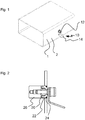
- FIG. 1 shows a facade part 1 with a freely accessible front side 2, in which a securing device 10 is inserted.
- a lock 12 secures a stop lug 14 in an at least two-part inner part 20 of the securing device 10, at least consisting of a front-side 2 weld-on part 22 and a harder inner end 26 facing inwardly.
- a and b welding part 22 is shown after a special insertion with a welding robot set and held in the same surface in an opening of the front 2, while a circumferential Weld 24 is placed in a designated throat so that on the welding part 22 and the front side 2 away a flat surface can be ground.
- the hardened inner end 26 has namely radially inwardly a dimensionally stable inner circumferential retaining groove 25 for receiving radially outwardly striving lock nipples 35 of the lock 12.
- the inner end 26 preferably has a radial internal thread 27 into which a cylinder screw can be screwed instead of the lock, or else a welding robot arm.
Landscapes
- Engineering & Computer Science (AREA)
- General Engineering & Computer Science (AREA)
- Mechanical Engineering (AREA)
- Architecture (AREA)
- Civil Engineering (AREA)
- Structural Engineering (AREA)
- Connection Of Plates (AREA)
- Load-Bearing And Curtain Walls (AREA)
Abstract
Description
- Die Erfindung betrifft eine Sicherungsvorrichtung und ein Sicherungsverfahren nach einem der Hauptansprüche.
- Es gibt beispielsweise Hausfassaden, die nur sauber zu halten sind, in dem sie ständig von Reinigungspersonal oder einem Robotersystem beklettert oder abgefahren werden. Bei großen Gebäuden oder besonders zerklüfteten Fassaden mit Rücksprüngen usw. kann das zusätzlich durch Wind und Wetter erschwert sein.
- Für solche Wandfassaden, die mit Wandplatten verkleidet sind, oder eine Art Hohlträgerfachwerk an Teiloberflächen aufweisen kommt eine Anbringung von Absturzsicherungen in Betracht.
- Das Problem wird erfindungsgemäß gelöst durch eine Sicherungsvorrichtung nach Anspruch 1 und ein Sicherungsverfahren nach Anspruch 2.
- Details der Erfindung sind den beigefügten Zeichnungsblättern zu entnehmen, wobei hier bevorzugte Ausführungsformen dargestellt sind.
-
Figur 1 zeigt ein Fassadenteil 1 mit einer frei zugänglichen Vorderseite 2, in die eine Sicherungsvorrichtung 10 eingesetzt ist. Ein Schloss 12 sichert eine Anschlagöse 14 in einem zumindest zweiteiligen Innenteils 20 der Sicherungsvorrichtung 10, zumindest bestehend aus einem vorderseitigen 2 Anschweißteil 22 und einem frei nach innen weisenden härteren Innenabschluss 26. - Das in den
Figuren 2 und3 a und b dargestellte Anschweißteil 22 wird nach einem besonderen Einsetzverfahren mit einem Schweißroboter oberflächengleich in eine Öffnung der Vorderseite 2 gesetzt und gehalten, während eine umlaufende Schweißnaht 24 in einer dafür vorgesehene Kehle gelegt wird, sodass über das Anschweißteil 22 und die Vorderseite 2 hinweg eine plane Oberfläche geschliffen werden kann. - Die Zweiteiligkeit des Innenteils 20, bestehend aus dem auf den gehärteten Innenabschluss 26 vorzugsweise geklebten Anschweißteil 22 aus weicherem Material, ermöglicht es, dass vorne angeschweißt werden kann und innen ein hochpräzises langlebiges Sicherungsgehäuse zur Verfügung gestellt ist. Der gehärtete Innenabschluss 26 weist nämlich radial innen eine dimensionsstabile innere umlaufende Haltenut 25 zur Aufnahme von nach radial außen strebenden Schlossnippeln 35 des Schlosses 12 auf.
- Innen weist der Innenabschluss 26 bevorzugt ein Radialinnengewinde 27 auf, in welches statt des Schlosses eine Zylinderschraube einschraubbar ist, oder auch ein Schweißroboterarm.
-
- 1
- Fassadenteil
- 2
- Vorderseite
- 10
- Sicherungsvorrichtung
- 12
- Schloss
- 14
- Anschlagöse
- 20
- Innenteil
- 22
- Anschweißteil
- 24
- Schweißnaht
- 25
- Haltenut
- 26
- Innenabschluss
- 27
- Radialinnengewinde
- 35
- Schlossnippel
Claims (2)
- Sicherungsvorrichtung 10 zum Einsetzen in ein Fassadenteil 1, beispielsweise in ein Blech, mit einem von außen zugänglichen Schloss 12, dass eine Anschlagöse 14 am Fassadenteil hält, wobei das Schloss 12 in ein zweiteiliges Innenteil 20 einzugreifen bestimmt ist, welches Innenteil 20 dem Schloss 12 abgewandt nach innen hin einen gehärteten Innenabschluss 26 und zur Vorderseite 2 des Fassadenteils 1 hin ein weicheres Anschweißteil 22 aufweist, und wobei das Schloss 12 von radial innen verriegelbar und lösbar in den Innenabschluss 26 greift.
- Sicherungsverfahren zum Sichern in einer an einer Fassade 1 befestigten Anschlagöse 14, bei dem zum Einsetzen eines die Anschlagöse 14 tragenden Schlosses 12 ein männliches Sicherungselement radial innen und koaxial in ein weibliches, flächenbündig mit der Fassade 1 abschließendes Innenteil 20 eingeführt wird, bis selbsttätig in dem Sicherungselement 10 gelagerte Eingriffselemente nach radial außen in eine umlaufende Aussparung des Innenteils 20 fahren, welcher Sicherungsvorgang dadurch reversibel ist, dass außen auf das Schloss 12 ein Lösungsdruck wirkt, bevorzugt auf einen zentral in einem Zugkranz des Schlosses 12 angeordneten Druckknopf.
Applications Claiming Priority (1)
| Application Number | Priority Date | Filing Date | Title |
|---|---|---|---|
| DE102018103820.8A DE102018103820A1 (de) | 2018-02-20 | 2018-02-20 | Sicherungsvorrichtung und Sicherungsverfahren |
Publications (3)
| Publication Number | Publication Date |
|---|---|
| EP3527747A1 true EP3527747A1 (de) | 2019-08-21 |
| EP3527747B1 EP3527747B1 (de) | 2024-03-20 |
| EP3527747C0 EP3527747C0 (de) | 2024-03-20 |
Family
ID=65493859
Family Applications (1)
| Application Number | Title | Priority Date | Filing Date |
|---|---|---|---|
| EP19157640.4A Active EP3527747B1 (de) | 2018-02-20 | 2019-02-18 | Sicherungsvorrichtung und sicherungsverfahren |
Country Status (2)
| Country | Link |
|---|---|
| EP (1) | EP3527747B1 (de) |
| DE (1) | DE102018103820A1 (de) |
Citations (4)
| Publication number | Priority date | Publication date | Assignee | Title |
|---|---|---|---|---|
| EP0379282A2 (de) * | 1989-01-16 | 1990-07-25 | Latchways Limited | Lösbare Verbindungs- oder Befestigungsvorrichtung |
| US6068226A (en) * | 1997-01-28 | 2000-05-30 | Anders; Glen | Detachable anchor |
| DE20316970U1 (de) * | 2003-11-03 | 2004-02-26 | Beckers, Ludwig | Befestigungselement in Form eines Ringbolzens |
| DE202011105177U1 (de) * | 2011-08-31 | 2011-11-09 | Skylotec Gmbh | Sicherungsöse und Sicherungssystem |
Family Cites Families (1)
| Publication number | Priority date | Publication date | Assignee | Title |
|---|---|---|---|---|
| US6551041B2 (en) * | 2000-09-13 | 2003-04-22 | Gary E. Choate | Quick connect/disconnect fall arrest anchorage with permanent connectors |
-
2018
- 2018-02-20 DE DE102018103820.8A patent/DE102018103820A1/de not_active Withdrawn
-
2019
- 2019-02-18 EP EP19157640.4A patent/EP3527747B1/de active Active
Patent Citations (4)
| Publication number | Priority date | Publication date | Assignee | Title |
|---|---|---|---|---|
| EP0379282A2 (de) * | 1989-01-16 | 1990-07-25 | Latchways Limited | Lösbare Verbindungs- oder Befestigungsvorrichtung |
| US6068226A (en) * | 1997-01-28 | 2000-05-30 | Anders; Glen | Detachable anchor |
| DE20316970U1 (de) * | 2003-11-03 | 2004-02-26 | Beckers, Ludwig | Befestigungselement in Form eines Ringbolzens |
| DE202011105177U1 (de) * | 2011-08-31 | 2011-11-09 | Skylotec Gmbh | Sicherungsöse und Sicherungssystem |
Also Published As
| Publication number | Publication date |
|---|---|
| EP3527747B1 (de) | 2024-03-20 |
| DE102018103820A1 (de) | 2019-08-22 |
| EP3527747C0 (de) | 2024-03-20 |
Similar Documents
| Publication | Publication Date | Title |
|---|---|---|
| DE69614593T2 (de) | Verankerungseinheit mit einem durch das auf den Bolzen einwirkende Drehmoment ausweitbaren Verankerungsteil | |
| DE2257821A1 (de) | Schubgesicherte muffenverbindung fuer rohre und rohrelemente | |
| DE3420696C1 (de) | Klemmbeschlag für die Befestigung und/oder Verbindung von Glasscheiben, insbesondere für Fassadenplatten aus Einscheibensicherheitsglas | |
| EP3527747A1 (de) | Sicherungsvorrichtung und sicherungsverfahren | |
| DE202015002187U1 (de) | Stütze und Klemmteile zum Montieren von Bauelementen, insbesondere im Trockenbau und für die Überkopfmontage | |
| DE1871814U (de) | Anordnung zur gewindelosen verbindung fester rohrleitungen, -gelaender oder -traggerueste. | |
| EP0523393B1 (de) | Schraube zum Einbringen in einen Spreizdübel | |
| EP2508693B1 (de) | Montagestopfen zum Montieren einer Ankerhülse an einer Schalung | |
| DE952044C (de) | Kaefigmutter | |
| DE3117441C2 (de) | Vorrichtung zur Befestigung einer Fassadenplatte vor einer Bauwerksaußenwand | |
| DE7435096U (de) | Befestigungselement für Fassadenunterkonstruktionen | |
| DE102015105372B4 (de) | Reinigungsvorrichtung | |
| DE202007013678U1 (de) | Halterungsvorrichtung für einen Grabstein eines Grabmals | |
| DE102021129471A1 (de) | Verfahren zur Montage eines Verstärkungsprofils auf Blendrahmen von Fenstern und Montagehilfe zur Durchführung des Verfahrens | |
| CH423177A (de) | Futterrahmen für Türen und Verfahren zur Herstellung desselben | |
| DE102007008235B4 (de) | Rohrverbindung | |
| CN210714264U (zh) | 以地弹簧为转轴的木质门 | |
| DE1913364C (de) | Haltebolzen fur Bekleidungsplatten od dgl sowie Verfahren zum Einsetzen eines solchen Haltebolzens | |
| DE102007061781A1 (de) | Befestigungsvorrichtung für zwischen Pfosten anzuordnende Zaun- oder Sicherschutzelemente | |
| EP0158848B1 (de) | Gitterelement für die Herstellung von Sicherheitsgittern | |
| DE102007046922A1 (de) | Halterungsvorrichtung für einen Grabstein eines Grabmals | |
| DE102007026080A1 (de) | Halterungsanordnung | |
| DE102015003685A1 (de) | Stütze und Klemmteil zum Montieren von Bauelementen, insbesondere im Trockenbau und für die Überkopfmontage | |
| EP1655819B1 (de) | Elektromotor | |
| DE29806472U1 (de) | Schnellmontage-Sicherungsbolzen für Gebäudewände mit Vormontage einer Betonhülse in der Gebäudewandschalung |
Legal Events
| Date | Code | Title | Description |
|---|---|---|---|
| PUAI | Public reference made under article 153(3) epc to a published international application that has entered the european phase |
Free format text: ORIGINAL CODE: 0009012 |
|
| STAA | Information on the status of an ep patent application or granted ep patent |
Free format text: STATUS: THE APPLICATION HAS BEEN PUBLISHED |
|
| AK | Designated contracting states |
Kind code of ref document: A1 Designated state(s): AL AT BE BG CH CY CZ DE DK EE ES FI FR GB GR HR HU IE IS IT LI LT LU LV MC MK MT NL NO PL PT RO RS SE SI SK SM TR |
|
| AX | Request for extension of the european patent |
Extension state: BA ME |
|
| STAA | Information on the status of an ep patent application or granted ep patent |
Free format text: STATUS: REQUEST FOR EXAMINATION WAS MADE |
|
| 17P | Request for examination filed |
Effective date: 20200221 |
|
| RBV | Designated contracting states (corrected) |
Designated state(s): AL AT BE BG CH CY CZ DE DK EE ES FI FR GB GR HR HU IE IS IT LI LT LU LV MC MK MT NL NO PL PT RO RS SE SI SK SM TR |
|
| STAA | Information on the status of an ep patent application or granted ep patent |
Free format text: STATUS: EXAMINATION IS IN PROGRESS |
|
| 17Q | First examination report despatched |
Effective date: 20200728 |
|
| GRAP | Despatch of communication of intention to grant a patent |
Free format text: ORIGINAL CODE: EPIDOSNIGR1 |
|
| STAA | Information on the status of an ep patent application or granted ep patent |
Free format text: STATUS: GRANT OF PATENT IS INTENDED |
|
| INTG | Intention to grant announced |
Effective date: 20231219 |
|
| GRAS | Grant fee paid |
Free format text: ORIGINAL CODE: EPIDOSNIGR3 |
|
| GRAA | (expected) grant |
Free format text: ORIGINAL CODE: 0009210 |
|
| STAA | Information on the status of an ep patent application or granted ep patent |
Free format text: STATUS: THE PATENT HAS BEEN GRANTED |
|
| AK | Designated contracting states |
Kind code of ref document: B1 Designated state(s): AL AT BE BG CH CY CZ DE DK EE ES FI FR GB GR HR HU IE IS IT LI LT LU LV MC MK MT NL NO PL PT RO RS SE SI SK SM TR |
|
| REG | Reference to a national code |
Ref country code: GB Ref legal event code: FG4D Free format text: NOT ENGLISH |
|
| REG | Reference to a national code |
Ref country code: CH Ref legal event code: EP |
|
| REG | Reference to a national code |
Ref country code: IE Ref legal event code: FG4D Free format text: LANGUAGE OF EP DOCUMENT: GERMAN |
|
| REG | Reference to a national code |
Ref country code: DE Ref legal event code: R096 Ref document number: 502019010825 Country of ref document: DE |
|
| U01 | Request for unitary effect filed |
Effective date: 20240320 |
|
| U07 | Unitary effect registered |
Designated state(s): AT BE BG DE DK EE FI FR IT LT LU LV MT NL PT SE SI Effective date: 20240325 |
|
| PG25 | Lapsed in a contracting state [announced via postgrant information from national office to epo] |
Ref country code: GR Free format text: LAPSE BECAUSE OF FAILURE TO SUBMIT A TRANSLATION OF THE DESCRIPTION OR TO PAY THE FEE WITHIN THE PRESCRIBED TIME-LIMIT Effective date: 20240621 |
|
| PG25 | Lapsed in a contracting state [announced via postgrant information from national office to epo] |
Ref country code: RS Free format text: LAPSE BECAUSE OF FAILURE TO SUBMIT A TRANSLATION OF THE DESCRIPTION OR TO PAY THE FEE WITHIN THE PRESCRIBED TIME-LIMIT Effective date: 20240620 Ref country code: HR Free format text: LAPSE BECAUSE OF FAILURE TO SUBMIT A TRANSLATION OF THE DESCRIPTION OR TO PAY THE FEE WITHIN THE PRESCRIBED TIME-LIMIT Effective date: 20240320 |
|
| PG25 | Lapsed in a contracting state [announced via postgrant information from national office to epo] |
Ref country code: RS Free format text: LAPSE BECAUSE OF FAILURE TO SUBMIT A TRANSLATION OF THE DESCRIPTION OR TO PAY THE FEE WITHIN THE PRESCRIBED TIME-LIMIT Effective date: 20240620 Ref country code: NO Free format text: LAPSE BECAUSE OF FAILURE TO SUBMIT A TRANSLATION OF THE DESCRIPTION OR TO PAY THE FEE WITHIN THE PRESCRIBED TIME-LIMIT Effective date: 20240620 Ref country code: HR Free format text: LAPSE BECAUSE OF FAILURE TO SUBMIT A TRANSLATION OF THE DESCRIPTION OR TO PAY THE FEE WITHIN THE PRESCRIBED TIME-LIMIT Effective date: 20240320 Ref country code: GR Free format text: LAPSE BECAUSE OF FAILURE TO SUBMIT A TRANSLATION OF THE DESCRIPTION OR TO PAY THE FEE WITHIN THE PRESCRIBED TIME-LIMIT Effective date: 20240621 |
|
| U79 | Statement concerning licences of right filed [unitary effect] |
Effective date: 20240705 |
|
| PG25 | Lapsed in a contracting state [announced via postgrant information from national office to epo] |
Ref country code: IS Free format text: LAPSE BECAUSE OF FAILURE TO SUBMIT A TRANSLATION OF THE DESCRIPTION OR TO PAY THE FEE WITHIN THE PRESCRIBED TIME-LIMIT Effective date: 20240720 |
|
| PG25 | Lapsed in a contracting state [announced via postgrant information from national office to epo] |
Ref country code: SM Free format text: LAPSE BECAUSE OF FAILURE TO SUBMIT A TRANSLATION OF THE DESCRIPTION OR TO PAY THE FEE WITHIN THE PRESCRIBED TIME-LIMIT Effective date: 20240320 |
|
| PG25 | Lapsed in a contracting state [announced via postgrant information from national office to epo] |
Ref country code: ES Free format text: LAPSE BECAUSE OF FAILURE TO SUBMIT A TRANSLATION OF THE DESCRIPTION OR TO PAY THE FEE WITHIN THE PRESCRIBED TIME-LIMIT Effective date: 20240320 |
|
| PG25 | Lapsed in a contracting state [announced via postgrant information from national office to epo] |
Ref country code: CZ Free format text: LAPSE BECAUSE OF FAILURE TO SUBMIT A TRANSLATION OF THE DESCRIPTION OR TO PAY THE FEE WITHIN THE PRESCRIBED TIME-LIMIT Effective date: 20240320 |
|
| PG25 | Lapsed in a contracting state [announced via postgrant information from national office to epo] |
Ref country code: PL Free format text: LAPSE BECAUSE OF FAILURE TO SUBMIT A TRANSLATION OF THE DESCRIPTION OR TO PAY THE FEE WITHIN THE PRESCRIBED TIME-LIMIT Effective date: 20240320 |
|
| PG25 | Lapsed in a contracting state [announced via postgrant information from national office to epo] |
Ref country code: SK Free format text: LAPSE BECAUSE OF FAILURE TO SUBMIT A TRANSLATION OF THE DESCRIPTION OR TO PAY THE FEE WITHIN THE PRESCRIBED TIME-LIMIT Effective date: 20240320 |
|
| PG25 | Lapsed in a contracting state [announced via postgrant information from national office to epo] |
Ref country code: SM Free format text: LAPSE BECAUSE OF FAILURE TO SUBMIT A TRANSLATION OF THE DESCRIPTION OR TO PAY THE FEE WITHIN THE PRESCRIBED TIME-LIMIT Effective date: 20240320 Ref country code: SK Free format text: LAPSE BECAUSE OF FAILURE TO SUBMIT A TRANSLATION OF THE DESCRIPTION OR TO PAY THE FEE WITHIN THE PRESCRIBED TIME-LIMIT Effective date: 20240320 Ref country code: RO Free format text: LAPSE BECAUSE OF FAILURE TO SUBMIT A TRANSLATION OF THE DESCRIPTION OR TO PAY THE FEE WITHIN THE PRESCRIBED TIME-LIMIT Effective date: 20240320 Ref country code: PL Free format text: LAPSE BECAUSE OF FAILURE TO SUBMIT A TRANSLATION OF THE DESCRIPTION OR TO PAY THE FEE WITHIN THE PRESCRIBED TIME-LIMIT Effective date: 20240320 Ref country code: IS Free format text: LAPSE BECAUSE OF FAILURE TO SUBMIT A TRANSLATION OF THE DESCRIPTION OR TO PAY THE FEE WITHIN THE PRESCRIBED TIME-LIMIT Effective date: 20240720 Ref country code: ES Free format text: LAPSE BECAUSE OF FAILURE TO SUBMIT A TRANSLATION OF THE DESCRIPTION OR TO PAY THE FEE WITHIN THE PRESCRIBED TIME-LIMIT Effective date: 20240320 Ref country code: CZ Free format text: LAPSE BECAUSE OF FAILURE TO SUBMIT A TRANSLATION OF THE DESCRIPTION OR TO PAY THE FEE WITHIN THE PRESCRIBED TIME-LIMIT Effective date: 20240320 |
|
| REG | Reference to a national code |
Ref country code: DE Ref legal event code: R097 Ref document number: 502019010825 Country of ref document: DE |
|
| U20 | Renewal fee for the european patent with unitary effect paid |
Year of fee payment: 7 Effective date: 20241204 |
|
| PLBE | No opposition filed within time limit |
Free format text: ORIGINAL CODE: 0009261 |
|
| STAA | Information on the status of an ep patent application or granted ep patent |
Free format text: STATUS: NO OPPOSITION FILED WITHIN TIME LIMIT |
|
| 26N | No opposition filed |
Effective date: 20241223 |
|
| PG25 | Lapsed in a contracting state [announced via postgrant information from national office to epo] |
Ref country code: MC Free format text: LAPSE BECAUSE OF FAILURE TO SUBMIT A TRANSLATION OF THE DESCRIPTION OR TO PAY THE FEE WITHIN THE PRESCRIBED TIME-LIMIT Effective date: 20240320 |
|
| GBPC | Gb: european patent ceased through non-payment of renewal fee |
Effective date: 20250218 |
|
| U20 | Renewal fee for the european patent with unitary effect paid |
Year of fee payment: 8 Effective date: 20251203 |
|
| PG25 | Lapsed in a contracting state [announced via postgrant information from national office to epo] |
Ref country code: GB Free format text: LAPSE BECAUSE OF NON-PAYMENT OF DUE FEES Effective date: 20250218 |
|
| PG25 | Lapsed in a contracting state [announced via postgrant information from national office to epo] |
Ref country code: IE Free format text: LAPSE BECAUSE OF NON-PAYMENT OF DUE FEES Effective date: 20250218 |
|
| REG | Reference to a national code |
Ref country code: CH Ref legal event code: U11 Free format text: ST27 STATUS EVENT CODE: U-0-0-U10-U11 (AS PROVIDED BY THE NATIONAL OFFICE) Effective date: 20260301 |
|
| PGFP | Annual fee paid to national office [announced via postgrant information from national office to epo] |
Ref country code: CH Payment date: 20260301 Year of fee payment: 8 |