EP3527395A1 - Vorrichtung sowie verfahren zur durchführung wenigstens eines schnittvorganges - Google Patents
Vorrichtung sowie verfahren zur durchführung wenigstens eines schnittvorganges Download PDFInfo
- Publication number
- EP3527395A1 EP3527395A1 EP19157659.4A EP19157659A EP3527395A1 EP 3527395 A1 EP3527395 A1 EP 3527395A1 EP 19157659 A EP19157659 A EP 19157659A EP 3527395 A1 EP3527395 A1 EP 3527395A1
- Authority
- EP
- European Patent Office
- Prior art keywords
- book
- cutting
- support
- force
- carrying
- Prior art date
- Legal status (The legal status is an assumption and is not a legal conclusion. Google has not performed a legal analysis and makes no representation as to the accuracy of the status listed.)
- Granted
Links
Images





Classifications
-
- B—PERFORMING OPERATIONS; TRANSPORTING
- B42—BOOKBINDING; ALBUMS; FILES; SPECIAL PRINTED MATTER
- B42C—BOOKBINDING
- B42C19/00—Multi-step processes for making books
- B42C19/08—Conveying between operating stations in machines
-
- B—PERFORMING OPERATIONS; TRANSPORTING
- B26—HAND CUTTING TOOLS; CUTTING; SEVERING
- B26D—CUTTING; DETAILS COMMON TO MACHINES FOR PERFORATING, PUNCHING, CUTTING-OUT, STAMPING-OUT OR SEVERING
- B26D7/00—Details of apparatus for cutting, cutting-out, stamping-out, punching, perforating, or severing by means other than cutting
- B26D7/01—Means for holding or positioning work
- B26D7/015—Means for holding or positioning work for sheet material or piles of sheets
-
- B—PERFORMING OPERATIONS; TRANSPORTING
- B26—HAND CUTTING TOOLS; CUTTING; SEVERING
- B26D—CUTTING; DETAILS COMMON TO MACHINES FOR PERFORATING, PUNCHING, CUTTING-OUT, STAMPING-OUT OR SEVERING
- B26D7/00—Details of apparatus for cutting, cutting-out, stamping-out, punching, perforating, or severing by means other than cutting
- B26D7/01—Means for holding or positioning work
- B26D7/015—Means for holding or positioning work for sheet material or piles of sheets
- B26D7/016—Back gauges
-
- B—PERFORMING OPERATIONS; TRANSPORTING
- B42—BOOKBINDING; ALBUMS; FILES; SPECIAL PRINTED MATTER
- B42C—BOOKBINDING
- B42C9/00—Applying glue or adhesive peculiar to bookbinding
- B42C9/02—Applying glue or adhesive peculiar to bookbinding for securing back linings, strips, ribbons or headbands
-
- B—PERFORMING OPERATIONS; TRANSPORTING
- B26—HAND CUTTING TOOLS; CUTTING; SEVERING
- B26D—CUTTING; DETAILS COMMON TO MACHINES FOR PERFORATING, PUNCHING, CUTTING-OUT, STAMPING-OUT OR SEVERING
- B26D7/00—Details of apparatus for cutting, cutting-out, stamping-out, punching, perforating, or severing by means other than cutting
- B26D2007/0012—Details, accessories or auxiliary or special operations not otherwise provided for
- B26D2007/0081—Cutting on three sides, e.g. trilateral trimming
Definitions
- the invention relates to a device and a method for carrying out at least one cutting operation for the purpose of producing a book, a booklet or the like, in particular a book-like identification document such as a passport book.
- a book includes pages tied to a spine.
- a book may include a book cover that includes covers.
- the book is brought to its final format by cropping the book on the non-bound pages of the book. This is necessary to be able to compensate for inaccuracies when cutting a sheet and to allow even edges of the book.
- books in particular passport books
- a device suitable for trimming in particular by pressing the book between two restraints.
- the respective book is held positionally stable.
- the back is formed by a form element, which connects the substantially parallel to each other arranged lid or the first and last pages of the book.
- a spine typically has a convex shape extending between said covers. He is therefore not held by the press of the book on the lids or the first and last pages positionally true.
- the book is trimmed, it can lead to deformations of the back and as a result to damage, especially in the form of slight tears on the lateral boundary of the back, especially at the point where the lateral boundary of the back in the lateral boundary edge of a connected cover or a cover page passes.
- These damages occur in various techniques for trimming, including cutting and milling. They reduce the visual impression of the book and should be prevented.
- the lateral boundaries of the spine are meant the areas which bound the spine at its opposite sides along its longitudinal extent.
- the object of the present invention is to provide an apparatus and a corresponding method for carrying out a cutting operation for the purpose of producing a book, which enable a cutting operation on a book in a simple and high-quality manner.
- a first aspect of the invention relates to an apparatus for carrying out at least one cutting operation for the purpose of producing a book comprising book pages bound to a spine.
- the device has a receiving element for receiving the book in a first plane, and a cutting unit for acting on the book with a cutting force substantially perpendicular to the plane.
- the device furthermore has at least one first support device with at least one first support element which is arranged or can be arranged to abut against at least one region of the back and thus counteracts at least one region of the back with one of the cutting force substantially when the cutting force is exerted on the book to support directed supporting force, that is, that the support element is designed to position a contact surface at an angle relative to the plane on this, which can be applied to the back of the book.
- a receiving element is e.g. to understand a die for pressing and thus fixing recording of the book during the cutting process.
- This embodiment of the device is advantageous because it allows support of the back and thus counteracts the deformation of the back and the associated damage in the form of slight tears in the region of the back.
- the device is set up such that the support element is set up and arranged or can be arranged so that it is flush or with a minimum distance of a maximum of 1 mm, in particular a maximum of 0.5 mm, with a second plane in which the cutting force applied to the book completes.
- the edge which is produced by a separation process, in particular by cutting or milling.
- the distance between the support element and the cutting tool or its cutting edge, when it performs the cutting process meant.
- the areas of the back are supported, which are in the vicinity of the edges or are limited by the edges that are produced by the cutting process.
- the device has a second supporting device designed in accordance with the first supporting device, whose supporting elements are configured and arranged or arrangeable such that at least these end regions can be supported by a respective supporting element during cutting operations on the opposite end regions of the back are.
- At least two support elements are designed and arranged or can be arranged such that with them during cutting operations at the opposite end regions of the back, at least these end regions can be supported by a respective support element, wherein the support elements are arranged on a common support device or on separate support devices.
- the end regions of the spine designate the regions of the spine which adjoin the edges which are produced by the cutting process.
- the embodiment according to the invention in which a plurality of support elements are present, allows effective support of several areas of the back in one step.
- the embodiment according to the invention in which a plurality of support elements are arranged on separate support devices, enables a time-saving arrangement of the individual support elements with respect to the back.
- the support element is set up and arranged or arrangeable such that it encloses the entire back in at least one respective end region of the back in a form-fitting manner.
- a support element it is possible for a support element to abut or be pressed against a part of the spine. Furthermore, it is possible that a support element or a plurality of support elements are formed such that it or they support the back over its entire length or support.
- the device is designed such that the support device is pneumatically driven or drivable to apply the support element to at least a part of the back.
- the pneumatic drive of this embodiment of the invention is advantageous because in pneumatically operated systems, the exhaust air can be discharged to the environment and therefore the device does not have to include return lines. This facilitates the maintenance of the device.
- the pressure force applied to the back can be adjusted very precisely or avoid overload.
- no contamination is to be feared.
- a further embodiment provides that the device according to the invention comprises at least one rotary joint, on which the support element is rotationally mounted, in order to apply the support element to at least a part of the back.
- This embodiment allows tilting of the support elements in the direction of the back. If the device comprises more than one support element, the support elements can be arranged on a common connection element that is rotatably mounted and allows common tilting of the support elements.
- a movement of the support elements in the direction of the back is made possible with a relatively inexpensive device.
- the movement of the support elements in the direction of the back is made possible by a tilting, which is caused by a vertical movement of a piston.
- a further aspect of the invention relates to a method for carrying out at least one cutting operation for the production of a book comprising book pages bound to a back, in which a book is fed to a device according to the invention, the book is received in or on the receiving element, the Book is fixed in or on the receiving element and the support member of the supporting device and the book are thereby positioned in relation to each other so that the support member rests against at least a portion of the back of the book.
- the book is acted upon by means of the cutting unit with at least one cutting force substantially perpendicular to the plane of the receiving element, wherein the support member against the effective direction of the cutting force exerts a supporting force on at least a portion of the back on the book.
- a separation process in particular the cutting or milling, exercised on at least one of the unbound pages of the book. It works one of the Supporting element exerted supporting force with at least one component perpendicular to the first plane and thus also against at least one component of the cutting force.
- the support element it is possible both for the support element to move in the direction of the book and for the book to be moved in the direction of the support element.
- An advantage of this embodiment of the method according to the invention is that prior to the cutting process, a support member and a back are positioned to each other such that the support element abuts the back and causes a force that counteracts the cutting force and thus can counteract damage in the area of the back.
- the support element is moved pneumatically and thus mechanically causes a pressure force on at least one region of the back.
- the pressing force caused by the support element acts positively against the cutting force or else with a component parallel to the plane of the receiving device for the purpose of non-positive fixation of the back region.
- the cutting operation is realized by a translational movement of a cutting element or by a rotary movement of a milling cutter.
- Damage to the back occurs both when trimming by a translationally moving cutting edge and when trimming by milling.
- the device according to the invention and the method according to the invention can, in particular in the case of these two common techniques of the cutting, counteract damage to the back and improve the visual impression of the book after the trimming. This allows a versatile applicability of the device according to the invention and the method according to the invention.
- a three-side trimming is carried out with the cutting device.
- a further embodiment of the invention provides that it can also be used in cutting devices which do not permit trimming on three sides without rearrangement of the book.
- the device according to the invention and the method according to the invention are versatile industrially applicable. You can for trimming different embodiments be used by books, brochures or the like. In particular, they can be used when trimming a book-type identification document such as a passport book.
- the book 30 is positioned with the aid of a transfer device with exact position on an upper receiving element 13 below the fixed upper clamping 14 and held there. Subsequently, the movable lower clamping 16 is pneumatically moved vertically upwards. The book 30 is pressed accurately between the upper clamping 14 and the lower clamping 16.
- the support device 20 is pneumatically actuated such that the support elements 24 of the support device are applied to the back 34 of the book and / or press against it. If the book 30 so braced, the cutting process, in particular the milling, the unbound pages 36 of the book.
- the Figures 1A and 1B show a detailed perspective view of a support device 20 for supporting a back 34 of a book during a cutting process for the production of the book 30.
- the support device 20 comprises two support elements 24 which are arranged individually on a common connecting element 22.
- the connecting element 22 is connected via a first rotary joint 19 pivotally connected to a part of a movable lower clamping 17.
- Via a further, second rotary joint 18, the connecting element 22 is pivotally connected to a first piston 42.
- the first piston 42 is arranged in a first cylinder 46 and pneumatically driven.
- This embodiment of the invention allows a tilting of a part of the support device 20, in particular of the connecting element 22 and consequently of the support elements 24 to the first rotary joint 19.
- Die Figure 1A shows an embodiment of the invention with retracted first piston 42, which means that the first piston 42 is in the retracted position in the first cylinder 46.
- the support elements 24 are in their starting position.
- the FIG. 1B shows an embodiment of the invention with extended first piston 42, which means that the first piston 42 has been moved within the first cylinder 46 upwards.
- the connecting element 22 is pivoted on the first rotary joint 19 and thus tilted.
- the support members 24 are tilted in comparison to the starting position, so that they, as will be explained below, can be applied or pressed against the back 34 of a book.
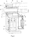
- FIGS. 2 to 7 each show a representation, partially in perspective, partially as a cutaway view of a section of a cutting device 10 which means a device for performing at least one cutting operation for the purpose of producing a book 30 is meant.
- the cutting device 10 comprises a housing 1 Figures 2 and 3 show the device 10 according to the invention with a book 30, which at the top Clamping 14 is positioned and with a movable lower clamping 16, which is in the starting position.
- the book 30 can be kept here for example due to a pneumatically generated negative pressure at the upper clamping 14.
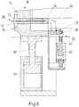
- the FIGS. 4 and 5 illustrate that the movable lower chuck 16 has been raised and the book 30 is pressed.
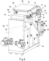
- the FIGS. 6 and 7 show how the support members 24 are positioned on the back 34 of the book. For clarity is in the Figures 2 . 4 and 6 the fixed upper clamping 14 is not shown.
- the movable lower clamping 16 is in its starting position, wherein the second piston 40 is in the retracted position in the second cylinder 44.
- the movable lower clamping 16 comprises the receiving element 12.
- the supporting device 20 is arranged on the movable lower clamping 16, so that it is also in the lower position.
- the support device 20 is in its initial position, in which the first piston 42 is in the retracted position in the first cylinder 46.
- first piston 42 and the second piston 40 are shown in the partially cutaway view of the device in FIG Fig. 3 shown.
- Fig. 2 is particularly well the arrangement of the first piston 42, connecting element 22 and the support elements 24 illustrated.
- FIGS. 4 and 5 show that the movable lower chuck 16 has been pneumatically moved to the book 30 and this presses.
- the second piston 40 is no longer in the retracted position in the second cylinder 44, but has been moved upwards.
- the book 30 is pressed accurately between upper clamping 14 and lower clamping 16 and thus clamped.
- the support device 20 has been arranged on the lower clamping 16 and moved together with the lower clamping 16.
- the first piston 42 has not been moved and is still in the retracted position in the first cylinder 46.
- the support device 20 is in its initial position.
- the position of the first piston 42 and the second piston 40 is particularly in Fig. 5 illustrated.
- FIGS. 6 and 7 show how starting from the position of the FIGS. 4 and 5 , the first piston 42 has been moved vertically upwards and as a result the support elements 24 of the support device 20 against the back 34 of the pressed book 30 and press against it.
- the connecting element 22 is arranged such that it is connected by means of the second rotary joint 18 with the first piston 42. Furthermore, the connecting element 22 is pivotable by means of the first rotary joint 19 with the lower Clamp 16 connected. By this arrangement, the connecting element 22 is tiltable. When the first piston 42 is moved vertically upward, the part of the connecting element 22 is also moved upwards, which is connected via the second rotary joint 18 with the first piston 42. The connecting element 22 is pivoted about the first rotary joint 19. This has the consequence that the connecting element 22 is tilted, that is, moves from its original position with respect to the receiving element 12 and the book 30. As a result, the support members 24 change their position with respect to the back 34 of the book and are applied against and / or press against it.
- the two support elements 24 abut one end region of the back 34 and / or are pressed against these regions.
- the support elements 24 are configured such that they can each apply to the back 34 over its entire thickness and / or be pressed. This is especially in Fig. 7 illustrated. This embodiment of the invention should not be construed as limiting the invention to this form.
- the invention also includes embodiments of the support elements 24, which lie only on a part of the back 34 of the book and / or pressed against it, preferably on the side of the book 30 facing away from the introduction of a cutting force F1.
- the present invention provides an economically interesting apparatus 10 as well as a corresponding method for carrying out a cutting operation for the production of a book 30, which makes possible a cutting operation which does not result in damage in the area of the back 34 of the book.
- this device 10 is designed for the production of a book-like identification document such as a passport book.
- a force F1 is exerted on the back 34 of the book. This causes a deformation of the back 34.
- the trimming takes place on the deformed spine so that faulty cut results, in particular tears and / or fraying in the area of the back 34, can occur.
- a cutting force F1 acts perpendicularly from above on the book 30.
- the support members 24 support the back 34. They cause a counterforce F2, which acts from the support member 24 from below on the back of the book 30, the cutting force F1 counteracts.
- the back 34 remains dimensionally stable during the cutting process and there is none faulty cut results in the area of the back 34, in particular tears and / or fraying.
Landscapes
- Life Sciences & Earth Sciences (AREA)
- Forests & Forestry (AREA)
- Engineering & Computer Science (AREA)
- Mechanical Engineering (AREA)
- Details Of Cutting Devices (AREA)
Abstract
Description
- Die Erfindung betrifft eine Vorrichtung sowie ein Verfahren zur Durchführung wenigstens eines Schnittvorganges zwecks Herstellung eines Buches, einer Broschüre oder dergleichen, insbesondere eines buchartigen Identifikationsdokumentes wie eines Passbuches.
- Ein Buch umfasst Seiten, die an einem Rücken gebunden sind. Zuzüglich zu den Seiten kann ein Buch einen Bucheinband umfassen, der Deckel umfasst. In einem der letzten Herstellungsschritte des Buches wird das Buch auf sein endgültiges Format gebracht, indem das Buch an den nicht gebundenen Seiten des Buches beschnitten wird. Dies ist notwendig, um Ungenauigkeiten beim Schneiden eines Druckbogens ausgleichen zu können und gleichmäßige Kanten des Buches zu ermöglichen.
- Nach dem Stand der Technik werden Bücher, insbesondere Passbücher, vor dem Beschnitt in einer für den Beschnitt geeigneten Vorrichtung fixiert, insbesondere durch das Pressen des Buches zwischen zwei Einspannungen. Dadurch wird das jeweilige Buch positionstreu gehalten.
- Der Rücken ist ausgebildet durch ein Formelement, welches die im Wesentlichen parallel zueinander angeordneten Deckel bzw. die erste und die letzte Seiten des Buches miteinander verbindet. Üblicherweise hat ein derartiger Rücken eine zwischen den genannten Deckeln bzw. Seiten verlaufende konvexe Form. Er wird daher nicht durch das Pressen des Buches an den Deckeln bzw. den ersten und letzten Seiten positionstreu gehalten. Beim Beschnitt des Buches kann es zu Verformungen des Rückens und infolgedessen zu Beschädigungen insbesondere in Form leichter Ausrisse an der seitlichen Begrenzung des Rückens kommen, insbesondere an der Stelle, an der die seitlichen Begrenzung des Rückens in die seitliche Begrenzungskante eines angeschlossenen Deckels bzw. einer Deckseite übergeht. Diese Beschädigungen treten bei verschiedenen Techniken für den Beschnitt, einschließlich dem Schneiden und dem Fräsen, auf. Sie mindern den optischen Eindruck des Buches und sollen verhindert werden. Mit den seitlichen Begrenzungen des Rückens sind die Bereiche gemeint, die den Rücken an dessen entlang seiner Längserstreckung gegenüberliegenden Seiten begrenzen.
- Die Aufgabe der vorliegenden Erfindung ist es, eine Vorrichtung sowie ein entsprechendes Verfahren zur Durchführung eines Schnittvorganges zwecks Herstellung eines Buches zur Verfügung zu stellen, welche in einfacher und qualitativ hochwertiger Weise einen Schnittvorgang an einem Buch ermöglichen.
- Diese Aufgabe wird durch die Vorrichtung zur Durchführung wenigstens eines Schnittvorganges nach Anspruch 1 und das Verfahren zur Durchführung wenigstens eines Schnittvorganges nach Anspruch 7 gelöst. Vorteilhafte Ausführungsformen der Vorrichtung sind in den Unteransprüchen 2 bis 6 angegeben. Vorteilhafte Ausführungsformen des Verfahrens sind in den Unteransprüchen 8 bis 10 angegeben. Diese und weitere Ausführungsformen werden im Folgenden beschrieben.
- Ein erster Aspekt der Erfindung betrifft eine Vorrichtung zur Durchführung wenigstens eines Schnittvorganges zwecks Herstellung eines Buches, welches Buchseiten umfasst, die an einem Rücken gebunden sind. Dabei weist die Vorrichtung ein Aufnahmeelement zur Aufnahme des Buches in einer ersten Ebene auf, sowie eine Schnitteinheit zur Beaufschlagung des Buches mit einer Schnittkraft im Wesentlichen senkrecht zur Ebene. Die Vorrichtung weist weiterhin mindestens eine erste Stützvorrichtung mit mindestens einem ersten Stützelement auf, das derart angeordnet oder anordbar ist, an wenigstens einem Bereich des Rückens anzuliegen und derart bei Einwirkung der Schnittkraft auf das Buch wenigstens einen Bereich des Rückens mit einer der Schnittkraft im Wesentlichen entgegen gerichteten Abstützkraft abzustützen, d.h., dass das Stützelement derart ausgebildet ist, eine Anlagefläche winklig in Bezug zur Ebene über diese zu positionieren, die an den Rücken des Buches anlegbar ist.
- Unter einem Aufnahmeelement ist dabei z.B. eine Matrize zur pressenden und damit fixierenden Aufnahme des Buches beim Schnittvorgang zu verstehen.
- Diese Ausführungsform der Vorrichtung ist von Vorteil, da sie ein Abstützen des Rückens ermöglicht und somit der Verformung des Rückens und der damit verbundenen Beschädigungen in Form leichter Ausrisse im Bereich des Rückens entgegenwirkt.
- Nach einer weiteren Ausführungsform ist die Vorrichtung derart eingerichtet, dass das Stützelement derart eingerichtet und angeordnet oder anordbar ist, dass es bündig oder mit einem minimalen Abstand von maximal 1 mm, insbesondere maximal 0,5 mm, mit einer zweiten Ebene, in der die Schnittkraft auf das Buch aufgebracht wird, abschließt.
- In der Ebene, in der die Schnittkraft auf das Buch aufgebracht wird, verläuft die Kante, die durch ein Trennverfahren, insbesondere durch Schneiden oder Fräsen, hergestellt wird. Mit anderen Worten ist der Abstand zwischen dem Stützelement und dem Schneidwerkzeug bzw. dessen Schneidkante, wenn es den Schnittvorgang vornimmt, gemeint.
- An dieser Ausführungsform ist insbesondere von Vorteil, dass die Bereiche des Rückens abgestützt werden, die sich in der Nähe der Kanten befinden bzw. von den Kanten begrenzt sind, die durch den Schnittvorgang hergestellt werden.
- Gemäß einer Ausführungsform der Erfindung ist vorgesehen, dass die Vorrichtung eine entsprechend der ersten Stützvorrichtung ausgestaltete zweite Stützvorrichtung aufweist, deren Stützelemente derart ausgestaltet und angeordnet oder anordbar sind, dass mit ihnen bei Schnittoperationen an den gegenüberliegenden Endbereichen des Rückens mindestens diese Endbereiche durch jeweils ein Stützelement abstützbar sind.
- Das bedeutet, dass mindestens zwei Stützelemente derart ausgestaltet und angeordnet oder anordbar sind, dass mit ihnen bei Schnittoperationen an den gegenüberliegenden Endbereichen des Rückens mindestens diese Endbereiche durch jeweils ein Stützelement abstützbar sind, wobei die Stützelemente auf einer gemeinsamen Stützvorrichtung oder auf separaten Stützvorrichtungen angeordnet sind.
- Dabei bezeichnen die Endbereiche des Rückens die Regionen des Rückens, die an die Kanten, die durch das Schnittverfahren hergestellt werden, angrenzen.
- Bei dieser erfindungsgemäßen Ausführungsform ist von Vorteil, dass gleichzeitig beide Endbereiche des Rückens abgestützt werden und der Beschnitt beider abgestützten Kanten möglich ist, ohne dass das Buch bewegt werden muss.
- Die erfindungsgemäße Ausführungsform, in der mehrere Stützelemente vorhanden sind, ermöglicht ein effektives Abstützen mehrerer Bereiche des Rückens in einem Arbeitsschritt. Die erfindungsgemäße Ausführungsform, in der mehrere Stützelemente auf separaten Stützvorrichtungen angeordnet sind, ermöglicht eine zeitsparende Anordnung der einzelnen Stützelemente bezüglich des Rückens.
- Nach einer weiteren Ausführungsform der Vorrichtungen ist das Stützelement derart eingerichtet und angeordnet oder anordbar, dass es formschlüssig den gesamten Rücken in mindestens einem jeweiligen Endbereich des Rückens umschließt.
- Der hier umschlossene, gesamte Rücken ist dabei beschrieben durch die Dicke des Buches, die die Ausdehnung des Rückens zwischen den Deckeln bzw. den ersten und letzten Seiten des Buches definiert.
- Bei dieser erfindungsgemäßen Ausführungsform ist von Vorteil, dass derart ein gleichmäßiger Druck auf den gesamten Rücken ausgeübt werden kann und über die gesamte Dicke des Buches eine Fixierung des Rückens bewirkt wird, sodass über die gesamte Breite des Rückens ein Ausreißen verhindert bzw. verringert wird.
- In den bisher beschriebenen Ausführungsformen der Vorrichtung ist es möglich, dass ein Stützelement an einem Teil des Rückens anliegt oder gepresst wird. Weiterhin ist möglich, dass ein Stützelement oder auch mehrere Stützelemente derart ausgebildet sind, dass es bzw. sie den Rücken über dessen gesamte Länge abstützt bzw. abstützen.
- Diese Ausführungsformen haben den Vorteil, dass eine Abstützung entlang der gesamten Länge des Rückens erfolgt und dadurch eine besonders große Stabilität vermittelt.
- Nach einer weiteren Ausführungsform ist die Vorrichtung derart ausgestaltet, dass die Stützvorrichtung pneumatisch angetrieben oder antreibbar ist, um das Stützelement an wenigstens einen Teil des Rückens anzulegen.
- Der pneumatische Antrieb dieser erfindungsgemäßen Ausführungsform ist von Vorteil, da bei pneumatisch betriebenen Systemen die Abluft an die Umgebung abgegeben werden kann und daher die Vorrichtung keine Rückleitungen umfassen muss. Dies erleichtert die Wartung der Vorrichtung. Zudem lässt sich aufgrund des programmatischen Antriebes die auf den Rücken realisierte Andruckkraft sehr genau einstellen bzw. eine Überlast vermeiden. Des Weiteren sind aufgrund der verwendeten Pneumatik keine Verunreinigungen zu befürchten.
- Eine weitere Ausführungsform sieht vor, dass die erfindungsgemäße Vorrichtung zumindest ein Rotationsgelenk umfasst, an dem das Stützelement rotatorisch gelagert ist, um das Stützelement an wenigstens einen Teil des Rückens anzulegen.
- Diese Ausführungsform ermöglicht ein Kippen der Stützelemente in Richtung des Rückens. Umfasst die Vorrichtung mehr als ein Stützelement, können die Stützelemente auf einem gemeinsamen Verbindungselement angeordnet sein, dass rotatorisch gelagert ist und ein gemeinsames Kippen der Stützelemente ermöglicht.
- Bei dieser Ausführungsform ist von Vorteil, dass mit einer relativ kostengünstigen Einrichtung eine Bewegung der Stützelemente in Richtung des Rückens ermöglicht wird. Die Bewegung der Stützelemente in Richtung des Rückens wird durch ein Kippen ermöglicht, das durch eine senkrechte Bewegung eines Kolbens bewirkt wird.
- Ein weiterer Aspekt der Erfindung betrifft ein Verfahren zur Durchführung wenigstens eines Schnittvorganges zwecks Herstellung eines Buches, welches Buchseiten umfasst, die an einem Rücken gebunden sind, bei dem ein Buch einer erfindungsgemäßen Vorrichtung zugeführt wird, das Buch in oder auf dem Aufnahmeelement aufgenommen wird, das Buch in oder auf dem Aufnahmeelement fixiert wird und das Stützelement der Stützvorrichtung und das Buch dabei derart in Bezug zueinander positioniert werden, dass das Stützelement an zumindest einem Teil des Rückens des Buches anliegt. Das Buch wird mittels der Schnitteinheit mit wenigstens einer Schnittkraft im Wesentlichen senkrecht zur Ebene des Aufnahmeelements beaufschlagt, wobei das Stützelement entgegen der Wirkrichtung der Schnittkraft eine Abstützkraft auf wenigstens einen Bereich des Rückens auf das Buch ausübt.
- Dabei wird ein Trennverfahren, insbesondere das Schneiden oder Fräsen, an mindestens einer der nicht gebundenen Seiten des Buches ausgeübt. Dabei wirkt eine von dem Stützelement ausgeübte Abstützkraft mit wenigstens einer Komponente senkrecht zur ersten Ebene und damit auch entgegen wenigstens einer Komponente der Schnittkraft.
- Gemäß der Erfindung ist es sowohl möglich, dass sich das Stützelement in Richtung des Buchens bewegt, als auch, dass das Buch in Richtung des Stützelementes bewegt wird.
- Vorteilhaft bei dieser erfindungsgemäßen Ausführungsform des Verfahrens ist, dass vor dem Schnittvorgang ein Stützelement und ein Rücken derart zueinander positioniert werden, dass das Stützelement am Rücken anliegt und eine Kraft bewirkt, die der Schnittkraft entgegenwirkt und so einer Beschädigung im Bereich des Rückens entgegenwirken kann.
- Nach einer weiteren Ausführungsform des Verfahrens wird das Stützelement pneumatisch bewegt und derart mechanisch eine Andruckkraft auf wenigstens einen Bereich des Rückens bewirkt.
- Dabei wirkt die vom Stützelement bewirkte Andruckkraft formschlüssig der Schnittkraft entgegen oder aber auch mit einer Komponente parallel zur Ebene der Aufnahmeeinrichtung zwecks kraftschlüssiger Fixierung des Rückenbereichs.
- Gemäß einer Ausführungsform des Verfahrens wird der Schnittvorgang durch eine translatorische Bewegung eines Schneidelements oder durch eine rotatorische Bewegung eines Fräsers realisiert.
- Beschädigungen des Rückens treten sowohl bei Beschnitt durch eine translatorisch bewegte Schneide als auch bei Beschnitt durch Fräsen auf. Die erfindungsgemäße Vorrichtung und das erfindungsgemäße Verfahren können insbesondere bei diesen beiden gängigen Techniken des Beschnitts einer Beschädigung des Rückens entgegenwirken und den optischen Eindruck des Buches nach dem Beschnitt verbessern. Dies ermöglicht eine vielseitige Einsetzbarkeit der erfindungsgemäßen Vorrichtung und des erfindungsgemäßen Verfahrens.
- Nach einer weiteren Ausführungsform des Verfahrens wird mit der Schnittvorrichtung ein Dreiseitenbeschnitt durchgeführt.
- Dies bedeutet, dass in der Schnittvorrichtung alle drei ungebundenen Seiten des Buches beschnitten werden können, ohne dass die Positionierung des Buches zwischen den einzelnen Schnitten verändert werden muss. Dies verringert den Arbeitsaufwand.
- Eine weitere Ausführungsform der Erfindung sieht vor, dass sie ebenfalls in Schnittvorrichtungen genutzt werden kann, die keinen Dreiseitenbeschnitt ohne eine Umlagerung des Buches erlauben.
- Die erfindungsgemäße Vorrichtung und das erfindungsgemäße Verfahren sind vielseitig gewerblich anwendbar. Sie können für den Beschnitt unterschiedlicher Ausführungsformen von Büchern, Broschüren oder dergleichen verwandt werden. Insbesondere können sie beim Beschnitt eines buchartigen Identifikationsdokumentes wie eines Passbuches eingesetzt werden.
- Im Folgenden werden weitere Aspekte der Erfindung anhand von Figuren beschrieben, aus denen weitere Ausführungsformen und Vorteile abgeleitet werden können.
-
Figur 1A zeigt eine perspektivische Darstellung einer Stützvorrichtung mit Stützelementen in einer Ausgangsposition. -
Figur 1B zeigt eine perspektivische Darstellung einer Stützvorrichtung mit gekippten Stützelementen. -
Figur 2 zeigt eine perspektivische Darstellung eines Ausschnitts einer erfindungsgemäßen Schnittvorrichtung, mit einer unteren Einspannung in einer Ausgangsposition. -
Figur 3 zeigt eine perspektivische, teilweise aufgeschnittene Ansicht eines Ausschnitts einer Schnittvorrichtung, mit einer unteren Einspannung in einer Ausgangsposition. -
Figur 4 zeigt eine perspektivische Darstellung eines Ausschnitts einer Schnittvorrichtung, mit einer unteren Einspannung in einer Position, in der ein Buch zwischen Einspannungen spannbar ist. -
Figur 5 zeigt eine teilweise aufgeschnittene Ansicht eines Ausschnitts einer Schnittvorrichtung, wobei die untere Einspannung sich in einer derartigen Position befindet, dass ein Buch zwischen Einspannungen verspannt ist. -
Figur 6 zeigt eine perspektivische Darstellung eines Ausschnitts einer Schnittvorrichtung, mit einer unteren Einspannung in einer Position, in der ein Buch zwischen den Einspannungen spannbar ist, wobei die Stützelemente an dem Rücken des Buches anliegen. -
Figur 7 zeigt eine perspektivische, teilweise aufgeschnittene Ansicht eines Ausschnitts einer Schnittvorrichtung, wobei sich die untere Einspannung in einer derartigen Position befindet, dass ein Buch zwischen den Einspannungen verspannt ist, wobei die Stützelemente an dem Rücken des Buches anliegen. -
Figur 8 zeigt eine Vergrößerung eines Ausschnittes derFig. 7 , in der die Wirkweise der Erfindung dargestellt ist. - Zur Beschreibung der Figuren und Erklärung des Verfahrens werden die Figuren und die Anwendungen lediglich anhand eines Buches beschrieben. Die Erfindung betrifft jedoch ebenfalls die Herstellung einer Broschüre oder dergleichen, so dass die Beschreibungen keine Einschränkung auf die Herstellung eines Buches bedeuten, sondern ebenso entsprechend für die Herstellung einer Broschüre oder dergleichen gelten.
- Das Buch 30 wird mit Hilfe einer Übergabevorrichtung positionsgenau an einem oberen Aufnahmeelement 13 unterhalb der festen oberen Einspannung 14 positioniert und dort gehalten. Im Anschluss daran wird die verfahrbare untere Einspannung 16 pneumatisch senkrecht nach oben bewegt. Das Buch 30 wird zwischen der oberen Einspannung 14 und der unteren Einspannung 16 positionsgenau gepresst. Die Stützvorrichtung 20 wird derart pneumatisch betätigt, dass die Stützelemente 24 der Stützvorrichtung an den Rücken 34 des Buches angelegt werden und/oder gegen ihn drücken. Ist das Buch 30 derart verspannt, erfolgt der Schnittvorgang, insbesondere das Fräsen, der nicht gebundenen Seiten 36 des Buches.
- Die
Figuren 1A und1B zeigen eine detaillierte perspektivische Darstellung einer Stützvorrichtung 20 zur Abstützung eines Rückens 34 eines Buches während eines Schnittvorganges zur Herstellung des Buches 30. Die Stützvorrichtung 20 umfasst zwei Stützelemente 24, die auf einem gemeinsamen Verbindungselement 22 einzeln angeordnet sind. Das Verbindungselement 22 ist über ein erstes Rotationsgelenk 19 schwenkbar mit einem Teil einer fahrbaren unteren Einspannung 17 verbunden. Über ein weiteres, zweites Rotationsgelenk 18 ist das Verbindungselement 22 schwenkbar mit einem ersten Kolben 42 verbunden. Der erste Kolben 42 ist in einem ersten Zylinder 46 angeordnet und pneumatisch antreibbar. Diese erfindungsgemäße Ausgestaltung ermöglicht ein Kippen eines Teils der Stützvorrichtung 20, insbesondere des Verbindungselementes 22 und infolgedessen der Stützelemente 24, um das erste Rotationsgelenk 19. DieFigur 1A zeigt eine erfindungsgemäße Ausführungsform mit eingefahrenem ersten Kolben 42, das bedeutet, dass sich der erste Kolben 42 in eingefahrener Position im ersten Zylinder 46 befindet. Die Stützelemente 24 befinden sich in ihrer Ausgangsposition. DieFigur 1B zeigt eine erfindungsgemäße Ausführungsform mit ausgefahrenem ersten Kolben 42, das bedeutet, dass der erste Kolben 42 innerhalb des ersten Zylinders 46 nach oben bewegt wurde. Das führt dazu, dass das Verbindungselement 22 am ersten Rotationsgelenk19 geschwenkt und somit gekippt wird. Infolgedessen sind die Stützelemente 24 im Vergleich zur Ausgangsposition gekippt, sodass sie, wie unten noch ausgeführt wird, an den Rücken 34 eines Buches angelegt oder angedrückt werden können. - Die
Figuren 2 bis 7 zeigen jeweils eine Darstellung, teilweise in perspektivischer Ausführung, teilweise als aufgeschnittene Ansicht, eines Ausschnitts einer Schnittvorrichtung 10 womit eine Vorrichtung zur Durchführung wenigstens eines Schnittvorganges zwecks Herstellung eines Buches 30 gemeint ist. Die Schnittvorrichtung 10 umfasst ein Gehäuse 1. DieFiguren 2 und3 zeigen die erfindungsgemäße Vorrichtung 10 mit einem Buch 30, das an der oberen Einspannung 14 positioniert ist und mit einer verfahrbaren unteren Einspannung 16, die sich in der Ausgangsposition befindet. Das Buch 30 kann hier zum Beispiel aufgrund eines pneumatisch erzeugten Unterdruckes an der oberen Einspannung 14 gehalten werden. DieFiguren 4 und5 illustrieren, dass die verfahrbare untere Einspannung 16 hochgefahren wurde und das Buch 30 gepresst wird. DieFiguren 6 und7 zeigen, wie die Stützelemente 24 an den Rücken 34 des Buches positioniert werden. Zur Übersichtlichkeit ist in denFiguren 2 ,4 und6 die feste obere Einspannung 14 nicht dargestellt. - In den
Figuren 2 und3 ist das Buch 30 bereits an der oberen Einspannung 14 positionsgenau platziert und wird in dieser Position gehalten. Die verfahrbare untere Einspannung 16 befindet sich in ihrer Ausgangsposition, wobei sich der zweite Kolben 40 in der eingefahrenen Position im zweiten Zylinder 44 befindet. Die verfahrbare untere Einspannung 16 umfasst das Aufnahmeelement 12. Die Stützvorrichtung 20 ist an der fahrbaren unteren Einspannung 16 angeordnet, sodass sie sich ebenfalls in der unteren Position befindet. Die Stützvorrichtung 20 befindet sich in ihrer Ausgangsposition, in der sich der erste Kolben 42 in eingefahrener Position im ersten Zylinder 46 befindet. - Die Position des ersten Kolbens 42 und des zweiten Kolbens 40 ist in der teilweise angeschnittenen Darstellung der Vorrichtung in
Fig. 3 dargestellt. InFig. 2 ist besonders gut die Anordnung des ersten Kolbens 42, Verbindungselement 22 und den Stützelementen 24 veranschaulicht. - Die
Figuren 4 und5 zeigen, dass die verfahrbare untere Einspannung 16 pneumatisch bis zum Buch 30 bewegt wurde und dieses presst. Der zweite Kolben 40 befindet sich nicht mehr in der eingefahrenen Position im zweiten Zylinder 44, sondern wurde nach oben bewegt. Das Buch 30 ist zwischen oberer Einspannung 14 und unterer Einspannung 16 positionsgenau gepresst und somit verspannt. Die Stützvorrichtung 20 ist an der unteren Einspannung 16 angeordnet und gemeinsam mit der unteren Einspannung 16 bewegt worden. Der erste Kolben 42 wurde nicht bewegt und befindet sich noch in der eingefahrenen Position im ersten Zylinder 46. Die Stützvorrichtung 20 befindet sich in ihrer Ausgangsposition. Die Position des ersten Kolbens 42 und des zweiten Kolbens 40 ist insbesondere inFig. 5 veranschaulicht. - Die
Figuren 6 und7 zeigen, wie ausgehend von der Position aus denFiguren 4 und5 , der erste Kolben 42 senkrecht nach oben bewegt wurde und sich infolgedessen die Stützelemente 24 der Stützvorrichtung 20 gegen den Rücken 34 des gepressten Buches 30 legen bzw. gegen ihn pressen. - Das Verbindungselement 22 ist derart angeordnet, dass es mittels des zweiten Rotationsgelenkes 18 mit dem ersten Kolben 42 verbunden ist. Des Weiteren ist das Verbindungselement 22 mittels des ersten Rotationsgelenkes 19 schwenkbar mit der unteren Einspannung 16 verbunden. Durch diese Anordnung ist das Verbindungselement 22 kippbar. Wird der erste Kolben 42 senkrecht nach oben bewegt, wird ebenfalls der Teil des Verbindungselements 22 nach oben bewegt, der über das zweite Rotationsgelenk 18 mit dem ersten Kolben 42 verbunden ist. Das Verbindungselement 22 wird um das erste Rotationsgelenk 19 geschwenkt. Dies hat zur Folge, dass das Verbindungselement 22 gekippt wird, sich also aus seiner ursprünglichen Position bezüglich des Aufnahmeelements 12 und des Buches 30 bewegt. Dies führt dazu, dass die Stützelemente 24 ihre Position bezüglich des Rückens 34 des Buches ändern und gegen ihn angelegt sind und/oder gegen ihn pressen. In der erfindungsgemäßen Ausgestaltungsform liegen die beiden Stützelemente 24 jeweils an jeweils einem Endbereich des Rückens 34 an und/oder werden gegen diese Bereiche gepresst. Die Stützelemente 24 sind derart ausgestaltet, dass sie sich jeweils an den Rücken 34 über seine gesamte Dicke anlegen können und/oder gepresst werden. Dies ist insbesondere in
Fig. 7 illustriert. Diese Ausgestaltungsform der Erfindung darf nicht als Beschränkung der Erfindung auf diese Form angesehen werden. Die Erfindung umfasst ebenso Ausgestaltungsformen der Stützelemente 24, die sich lediglich an einen Teil des Rückens 34 des Buches legen und/oder gegen diesen gepresst werden, vorzugsweise auf der der Einleitung einer Schnittkraft F1 abgewandten Seite des Buches 30. - Die vorliegende Erfindung stellt eine wirtschaftlich interessante Vorrichtung 10 sowie ein entsprechendes Verfahren zur Durchführung eines Schnittvorganges zwecks Herstellung eines Buches 30 zur Verfügung, welches einen Schnittvorgang ermöglicht, der keine Beschädigungen im Bereich des Rückens 34 des Buches zur Folge hat. Insbesondere, aber nicht darauf beschränkt, ist diese Vorrichtung 10 für die Herstellung eines buchartigen Identifikationsdokumentes wie eines Passbuches konzipiert. Beim Beschnitt eines Buches 30 kann es insbesondere im Bereich des Rückens 34 zu fehlerhaften Schnittresultaten kommen. Zwar wird das Buch 30 durch das Pressen zwischen oberer Einspannung 14 und unterer Einspannung 16 positionsgenau fixiert, der Rücken 34 des Buches behält jedoch Spiel, da die Einspannungen diesen Bereich nicht abstützen. Beim Schnittprozess wird eine Kraft F1 auf den Rücken 34 des Buches ausgeübt. Diese sorgt für eine Verformung des Rückens 34. Der Beschnitt findet an dem verformten Rücken statt, so dass es zu fehlerhaften Schnittresultaten, insbesondere Ausrissen und/oder Ausfransungen im Bereich des Rückens 34, kommen kann.
- In der
Figur 8 ist eine Wirkweise der Erfindung illustriert. Eine Schnittkraft F1 wirkt senkrecht von oben auf das Buch 30. Die Stützelemente 24 stützen den Rücken 34. Sie bewirken eine Gegenkraft F2, die von dem Stützelement 24 von unten auf den Rücken des Buches 30, der Schnittkraft F1 entgegen gerichtet, wirkt. Mittels der erfindungsgemäßen Stützelemente 24 bleibt der Rücken 34 während des Schnittvorganges formstabil und es kommt zu keinen fehlerhaften Schnittresultaten im Bereich des Rückens 34, insbesondere Ausrissen und/oder Ausfransungen.Bezugszeichenliste 1 Gehäuse 10 Sch nittvorrichtung 12 unteres Aufnahmeelement 13 oberes Aufnahmeelement 14 obere Einspannung 16 untere Einspannung 17 Teilbereich der unteren Einspannung 18 zweites Rotationsgelenk 19 erstes Rotationsgelenk 20 Stützvorrichtung 22 Verbindungselement 24 Stützelement 30 Buch 32 Deckel 34 Rücken 36 ungebundene Seite 40 zweiter Kolben 42 erster Kolben 44 zweiter Zylinder 46 erster Zylinder F1 Schnittkraft F2 Gegenkraft
Claims (10)
- Vorrichtung zur Durchführung wenigstens eines Schnittvorganges (10) zwecks Herstellung eines Buches (30), einer Broschüre oder dergleichen, insbesondere eines buchartigen Identifikationsdokumentes wie eines Passbuches, welches Buchseiten umfasst, die an einem Rücken (34) gebunden sind, wobei die Vorrichtung ein Aufnahmeelement (12, 13) zur Aufnahme des Buches (30) in einer ersten Ebene aufweist, sowie eine Schnitteinheit zur Beaufschlagung des Buches mit einer Schnittkraft im Wesentlichen senkrecht zur Ebene, dadurch gekennzeichnet, dass die Vorrichtung (10) weiterhin mindestens eine erste Stützvorrichtung (20) mit mindestens einem ersten Stützelement (24) aufweist, das derart angeordnet oder anordbar ist, an wenigstens einem Bereich des Rückens (34) anzuliegen und derart bei Einwirkung der Schnittkraft (F1) auf das Buch (30) wenigstens einen Bereich des Rückens (34) mit einer der Schnittkraft im Wesentlichen entgegen gerichteten Abstützkraft (F2) abzustützen, d.h., dass das Stützelement (24) derart ausgebildet ist, eine Anlagefläche winklig in Bezug zur Ebene über diese zu positionieren, die an den Rücken (34) des Buches anlegbar ist.
- Vorrichtung zur Durchführung wenigstens eines Schnittvorganges (10) gemäß Anspruch 1, dadurch gekennzeichnet, dass das Stützelement (24) derart eingerichtet und angeordnet oder anordbar ist, dass es bündig oder mit einem minimalen Abstand von maximal 1 mm, insbesondere maximal 0,5 mm, mit einer zweiten Ebene, in der die Schnittkraft (F1) auf das Buch (30) aufgebracht wird, abschließt.
- Vorrichtung zur Durchführung wenigstens eines Schnittvorganges (10) gemäß einem der Ansprüche 1 und 2, dadurch gekennzeichnet, dass die Vorrichtung eine entsprechend der ersten Stützvorrichtung (20) ausgestaltete zweite Stützvorrichtung (20) aufweist, deren Stützelemente (24) derart ausgestaltet und angeordnet oder anordbar sind, dass mit ihnen bei Schnittoperationen an den gegenüberliegenden Endbereichen des Rückens (34) mindestens diese Endbereiche durch jeweils ein Stützelement (24) abstützbar sind.
- Vorrichtung zur Durchführung wenigstens eines Schnittvorganges (10) gemäß einem der Ansprüche 1-3, dadurch gekennzeichnet, dass das Stützelement (24) derart eingerichtet und angeordnet oder anordbar ist, formschlüssig den gesamten Rücken (34) in mindestens einem jeweiligen Endbereich des Rückens (34) zu umschließen.
- Vorrichtung zur Durchführung wenigstens eines Schnittvorganges (10) gemäß einem der Ansprüche 1-4, dadurch gekennzeichnet, dass die Stützvorrichtung (20) pneumatisch angetrieben oder antreibbar ist, um das Stützelement (24) an wenigstens einen Teil des Rückens (34) anzulegen.
- Vorrichtung zur Durchführung wenigstens eines Schnittvorganges (10) gemäß einem der Ansprüche 1-5, dadurch gekennzeichnet, dass sie zumindest ein Rotationsgelenk (19) umfasst, an dem das Stützelement (24) rotatorisch gelagert ist, um das Stützelement (19) an wenigstens einen Teil des Rückens (34) anzulegen.
- Verfahren zur Durchführung wenigstens eines Schnittvorganges zwecks Herstellung eines Buches (30), einer Broschüre oder dergleichen, insbesondere eines buchartigen Identifikationsdokumentes wie eines Passbuches, welches Buchseiten umfasst, die an einem Rücken (34) gebunden sind, bei dem- ein Buch (30) einer Vorrichtung (10) gemäß mindestens einem der Ansprüche 1-6 zugeführt wird,- das Buch (30) in oder auf dem Aufnahmeelement (12, 13) aufgenommen wird,- das Buch (30) in oder auf dem Aufnahmeelement (12, 13) fixiert wird,- das Stützelement (24) der Stützvorrichtung (20) und das Buch (30) dabei derart in Bezug zueinander positioniert werden, dass das Stützelement (24) an zumindest einem Teil des Rückens (34) des Buches anliegt,- das Buch (30) mittels der Schnitteinheit mit wenigstens einer Schnittkraft (F1) im Wesentlichen senkrecht zur Ebene des Aufnahmeelements (12, 13) beaufschlagt wird, wobei das Stützelement (24) entgegen der Wirkrichtung der Schnittkraft (F1) eine Abstützkraft (F2) auf wenigstens einen Bereich des Rückens (34) auf das Buch ausübt.
- Verfahren nach Anspruch 7, dadurch gekennzeichnet, dass das Stützelement (24) pneumatisch bewegt wird und derart mechanisch eine Andruckkraft auf wenigstens einen Bereich des Rückens (34) bewirkt.
- Verfahren nach einem der Ansprüche 7 und 8, dadurch gekennzeichnet, dass der Schnittvorgang durch eine translatorische Bewegung eines Schneidelements oder durch eine rotatorische Bewegung eines Fräsers realisiert wird.
- Verfahren nach einem der Ansprüche 7 bis 9, dadurch gekennzeichnet, dass mit der Schnittvorrichtung (10) ein Dreiseitenschnitt durchgeführt wird.
Applications Claiming Priority (1)
| Application Number | Priority Date | Filing Date | Title |
|---|---|---|---|
| DE102018103615.9A DE102018103615A1 (de) | 2018-02-19 | 2018-02-19 | Vorrichtung sowie Verfahren zur Durchführung wenigstens eines Schnittvorganges |
Publications (2)
| Publication Number | Publication Date |
|---|---|
| EP3527395A1 true EP3527395A1 (de) | 2019-08-21 |
| EP3527395B1 EP3527395B1 (de) | 2021-03-31 |
Family
ID=65493865
Family Applications (1)
| Application Number | Title | Priority Date | Filing Date |
|---|---|---|---|
| EP19157659.4A Active EP3527395B1 (de) | 2018-02-19 | 2019-02-18 | Vorrichtung sowie verfahren zur durchführung wenigstens eines schnittvorganges |
Country Status (2)
| Country | Link |
|---|---|
| EP (1) | EP3527395B1 (de) |
| DE (1) | DE102018103615A1 (de) |
Citations (4)
| Publication number | Priority date | Publication date | Assignee | Title |
|---|---|---|---|---|
| DE1120423B (de) * | 1960-12-17 | 1961-12-28 | Atlas Werke Ag | Vorrichtung zum dreiseitigen Beschnitt von Buechern, Broschueren, Kalendern od. dgl. |
| DE1216240B (de) * | 1963-08-23 | 1966-05-12 | Chicago Machinery Lab Inc | Buchbeschneidemaschine |
| DE2426599A1 (de) * | 1973-06-26 | 1975-01-16 | Polygraph Leipzig | Dreimesserschneidemaschine fuer papier, pappe od.dgl |
| DE102008027131A1 (de) * | 2008-05-30 | 2009-12-03 | Picanol N.V. | Vorrichtung zum Trennen eines Schussfadens |
-
2018
- 2018-02-19 DE DE102018103615.9A patent/DE102018103615A1/de not_active Withdrawn
-
2019
- 2019-02-18 EP EP19157659.4A patent/EP3527395B1/de active Active
Patent Citations (4)
| Publication number | Priority date | Publication date | Assignee | Title |
|---|---|---|---|---|
| DE1120423B (de) * | 1960-12-17 | 1961-12-28 | Atlas Werke Ag | Vorrichtung zum dreiseitigen Beschnitt von Buechern, Broschueren, Kalendern od. dgl. |
| DE1216240B (de) * | 1963-08-23 | 1966-05-12 | Chicago Machinery Lab Inc | Buchbeschneidemaschine |
| DE2426599A1 (de) * | 1973-06-26 | 1975-01-16 | Polygraph Leipzig | Dreimesserschneidemaschine fuer papier, pappe od.dgl |
| DE102008027131A1 (de) * | 2008-05-30 | 2009-12-03 | Picanol N.V. | Vorrichtung zum Trennen eines Schussfadens |
Also Published As
| Publication number | Publication date |
|---|---|
| EP3527395B1 (de) | 2021-03-31 |
| DE102018103615A1 (de) | 2019-08-22 |
Similar Documents
| Publication | Publication Date | Title |
|---|---|---|
| EP1196269B1 (de) | Vorrichtung zum stanzen eines stapels aus blättrigem gut | |
| DE19820473B4 (de) | Verfahren und Vorrichtung zur Herstellung eines im Querschnitt abgekanteten und in Längsrichtung zumindest teilweise gebogenen Produktes | |
| DE2649765A1 (de) | Vorrichtung zum abbiegen von bauelementeanschlussleitungen nach innen oder nach aussen | |
| EP2874804A1 (de) | Keiltrieb | |
| EP2641682A1 (de) | Schneidvorrichtung und Verfahren zum Schneiden von Blech- oder Blockmaterial | |
| EP2147759B1 (de) | Verfahren und Vorrichtung für den Beschnitt wenigstens einer Seitenkante gebundener Druckerzeugnisse | |
| DE102007040278B4 (de) | Schneidvorrichtung zum Schneiden von aus Blättern gebildeten Stapeln | |
| DE2306011A1 (de) | Vorrichtung zur bearbeitung von druckplatten bzw. -formen mit einer duennen metallblechplatte als schichttraeger | |
| DE3047348A1 (de) | Werkstueck-klemmvorrichtung | |
| EP0418529A2 (de) | Vorrichtung für den dreiseitigen Beschnitt von Druckexemplaren | |
| DE102005009369A1 (de) | Mehrwinkel-Zuschneidevorrichtung | |
| EP1053890A1 (de) | Vorrichtung für den Beschnitt von Broschüren | |
| DE69423614T2 (de) | Verbesserungen an vorrichtungen zur herstellung von kartonzuschnitten | |
| EP3527340B1 (de) | Vorrichtung sowie verfahren zur durchführung wenigstens eines schnittvorganges | |
| EP3527395B1 (de) | Vorrichtung sowie verfahren zur durchführung wenigstens eines schnittvorganges | |
| DE3441198C2 (de) | ||
| EP2123412B1 (de) | Schneidemaschine zum Schneiden von gestapeltem, blattförmigem Gut sowie Verfahren | |
| EP0392047A1 (de) | Verfahren und Vorrichtung zum Heissverformen einer Kunstharz-Schichtpressstoffplatte | |
| DE3426563A1 (de) | Platten-biegevorrichtung | |
| EP3527341B1 (de) | Vorrichtung sowie verfahren zur durchführung wenigstens eines schnittvorganges | |
| DE202011109756U1 (de) | Schneidvorrichtung zum Schneiden von Blech- oder Blockmaterial | |
| DE653071C (de) | Verfahren und Vorrichtung zur Herstellung von Heftklammerstreifen | |
| DE2301089A1 (de) | Vorrichtung zum umbiegen einer tafel, platte o. dgl | |
| DE102022002466B4 (de) | Verfahren und Vorrichtung zur Herstellung eines Booklets | |
| DE202026100407U1 (de) | Ausklinkvorrichtung |
Legal Events
| Date | Code | Title | Description |
|---|---|---|---|
| PUAI | Public reference made under article 153(3) epc to a published international application that has entered the european phase |
Free format text: ORIGINAL CODE: 0009012 |
|
| STAA | Information on the status of an ep patent application or granted ep patent |
Free format text: STATUS: THE APPLICATION HAS BEEN PUBLISHED |
|
| AK | Designated contracting states |
Kind code of ref document: A1 Designated state(s): AL AT BE BG CH CY CZ DE DK EE ES FI FR GB GR HR HU IE IS IT LI LT LU LV MC MK MT NL NO PL PT RO RS SE SI SK SM TR |
|
| AX | Request for extension of the european patent |
Extension state: BA ME |
|
| STAA | Information on the status of an ep patent application or granted ep patent |
Free format text: STATUS: REQUEST FOR EXAMINATION WAS MADE |
|
| 17P | Request for examination filed |
Effective date: 20200219 |
|
| RBV | Designated contracting states (corrected) |
Designated state(s): AL AT BE BG CH CY CZ DE DK EE ES FI FR GB GR HR HU IE IS IT LI LT LU LV MC MK MT NL NO PL PT RO RS SE SI SK SM TR |
|
| GRAP | Despatch of communication of intention to grant a patent |
Free format text: ORIGINAL CODE: EPIDOSNIGR1 |
|
| STAA | Information on the status of an ep patent application or granted ep patent |
Free format text: STATUS: GRANT OF PATENT IS INTENDED |
|
| GRAJ | Information related to disapproval of communication of intention to grant by the applicant or resumption of examination proceedings by the epo deleted |
Free format text: ORIGINAL CODE: EPIDOSDIGR1 |
|
| STAA | Information on the status of an ep patent application or granted ep patent |
Free format text: STATUS: REQUEST FOR EXAMINATION WAS MADE |
|
| INTG | Intention to grant announced |
Effective date: 20201027 |
|
| GRAP | Despatch of communication of intention to grant a patent |
Free format text: ORIGINAL CODE: EPIDOSNIGR1 |
|
| STAA | Information on the status of an ep patent application or granted ep patent |
Free format text: STATUS: GRANT OF PATENT IS INTENDED |
|
| INTC | Intention to grant announced (deleted) | ||
| INTG | Intention to grant announced |
Effective date: 20201201 |
|
| GRAS | Grant fee paid |
Free format text: ORIGINAL CODE: EPIDOSNIGR3 |
|
| GRAA | (expected) grant |
Free format text: ORIGINAL CODE: 0009210 |
|
| STAA | Information on the status of an ep patent application or granted ep patent |
Free format text: STATUS: THE PATENT HAS BEEN GRANTED |
|
| AK | Designated contracting states |
Kind code of ref document: B1 Designated state(s): AL AT BE BG CH CY CZ DE DK EE ES FI FR GB GR HR HU IE IS IT LI LT LU LV MC MK MT NL NO PL PT RO RS SE SI SK SM TR |
|
| REG | Reference to a national code |
Ref country code: GB Ref legal event code: FG4D Free format text: NOT ENGLISH Ref country code: CH Ref legal event code: EP |
|
| REG | Reference to a national code |
Ref country code: AT Ref legal event code: REF Ref document number: 1376503 Country of ref document: AT Kind code of ref document: T Effective date: 20210415 |
|
| REG | Reference to a national code |
Ref country code: DE Ref legal event code: R096 Ref document number: 502019001073 Country of ref document: DE |
|
| REG | Reference to a national code |
Ref country code: IE Ref legal event code: FG4D Free format text: LANGUAGE OF EP DOCUMENT: GERMAN |
|
| REG | Reference to a national code |
Ref country code: LT Ref legal event code: MG9D |
|
| PG25 | Lapsed in a contracting state [announced via postgrant information from national office to epo] |
Ref country code: BG Free format text: LAPSE BECAUSE OF FAILURE TO SUBMIT A TRANSLATION OF THE DESCRIPTION OR TO PAY THE FEE WITHIN THE PRESCRIBED TIME-LIMIT Effective date: 20210630 Ref country code: HR Free format text: LAPSE BECAUSE OF FAILURE TO SUBMIT A TRANSLATION OF THE DESCRIPTION OR TO PAY THE FEE WITHIN THE PRESCRIBED TIME-LIMIT Effective date: 20210331 Ref country code: FI Free format text: LAPSE BECAUSE OF FAILURE TO SUBMIT A TRANSLATION OF THE DESCRIPTION OR TO PAY THE FEE WITHIN THE PRESCRIBED TIME-LIMIT Effective date: 20210331 Ref country code: NO Free format text: LAPSE BECAUSE OF FAILURE TO SUBMIT A TRANSLATION OF THE DESCRIPTION OR TO PAY THE FEE WITHIN THE PRESCRIBED TIME-LIMIT Effective date: 20210630 |
|
| PG25 | Lapsed in a contracting state [announced via postgrant information from national office to epo] |
Ref country code: RS Free format text: LAPSE BECAUSE OF FAILURE TO SUBMIT A TRANSLATION OF THE DESCRIPTION OR TO PAY THE FEE WITHIN THE PRESCRIBED TIME-LIMIT Effective date: 20210331 Ref country code: LV Free format text: LAPSE BECAUSE OF FAILURE TO SUBMIT A TRANSLATION OF THE DESCRIPTION OR TO PAY THE FEE WITHIN THE PRESCRIBED TIME-LIMIT Effective date: 20210331 Ref country code: SE Free format text: LAPSE BECAUSE OF FAILURE TO SUBMIT A TRANSLATION OF THE DESCRIPTION OR TO PAY THE FEE WITHIN THE PRESCRIBED TIME-LIMIT Effective date: 20210331 |
|
| REG | Reference to a national code |
Ref country code: NL Ref legal event code: MP Effective date: 20210331 |
|
| PG25 | Lapsed in a contracting state [announced via postgrant information from national office to epo] |
Ref country code: NL Free format text: LAPSE BECAUSE OF FAILURE TO SUBMIT A TRANSLATION OF THE DESCRIPTION OR TO PAY THE FEE WITHIN THE PRESCRIBED TIME-LIMIT Effective date: 20210331 Ref country code: SM Free format text: LAPSE BECAUSE OF FAILURE TO SUBMIT A TRANSLATION OF THE DESCRIPTION OR TO PAY THE FEE WITHIN THE PRESCRIBED TIME-LIMIT Effective date: 20210331 Ref country code: CZ Free format text: LAPSE BECAUSE OF FAILURE TO SUBMIT A TRANSLATION OF THE DESCRIPTION OR TO PAY THE FEE WITHIN THE PRESCRIBED TIME-LIMIT Effective date: 20210331 Ref country code: EE Free format text: LAPSE BECAUSE OF FAILURE TO SUBMIT A TRANSLATION OF THE DESCRIPTION OR TO PAY THE FEE WITHIN THE PRESCRIBED TIME-LIMIT Effective date: 20210331 Ref country code: LT Free format text: LAPSE BECAUSE OF FAILURE TO SUBMIT A TRANSLATION OF THE DESCRIPTION OR TO PAY THE FEE WITHIN THE PRESCRIBED TIME-LIMIT Effective date: 20210331 |
|
| PG25 | Lapsed in a contracting state [announced via postgrant information from national office to epo] |
Ref country code: IS Free format text: LAPSE BECAUSE OF FAILURE TO SUBMIT A TRANSLATION OF THE DESCRIPTION OR TO PAY THE FEE WITHIN THE PRESCRIBED TIME-LIMIT Effective date: 20210731 Ref country code: PL Free format text: LAPSE BECAUSE OF FAILURE TO SUBMIT A TRANSLATION OF THE DESCRIPTION OR TO PAY THE FEE WITHIN THE PRESCRIBED TIME-LIMIT Effective date: 20210331 Ref country code: RO Free format text: LAPSE BECAUSE OF FAILURE TO SUBMIT A TRANSLATION OF THE DESCRIPTION OR TO PAY THE FEE WITHIN THE PRESCRIBED TIME-LIMIT Effective date: 20210331 Ref country code: PT Free format text: LAPSE BECAUSE OF FAILURE TO SUBMIT A TRANSLATION OF THE DESCRIPTION OR TO PAY THE FEE WITHIN THE PRESCRIBED TIME-LIMIT Effective date: 20210802 Ref country code: SK Free format text: LAPSE BECAUSE OF FAILURE TO SUBMIT A TRANSLATION OF THE DESCRIPTION OR TO PAY THE FEE WITHIN THE PRESCRIBED TIME-LIMIT Effective date: 20210331 |
|
| REG | Reference to a national code |
Ref country code: DE Ref legal event code: R097 Ref document number: 502019001073 Country of ref document: DE |
|
| PG25 | Lapsed in a contracting state [announced via postgrant information from national office to epo] |
Ref country code: ES Free format text: LAPSE BECAUSE OF FAILURE TO SUBMIT A TRANSLATION OF THE DESCRIPTION OR TO PAY THE FEE WITHIN THE PRESCRIBED TIME-LIMIT Effective date: 20210331 Ref country code: DK Free format text: LAPSE BECAUSE OF FAILURE TO SUBMIT A TRANSLATION OF THE DESCRIPTION OR TO PAY THE FEE WITHIN THE PRESCRIBED TIME-LIMIT Effective date: 20210331 Ref country code: AL Free format text: LAPSE BECAUSE OF FAILURE TO SUBMIT A TRANSLATION OF THE DESCRIPTION OR TO PAY THE FEE WITHIN THE PRESCRIBED TIME-LIMIT Effective date: 20210331 |
|
| PLBE | No opposition filed within time limit |
Free format text: ORIGINAL CODE: 0009261 |
|
| STAA | Information on the status of an ep patent application or granted ep patent |
Free format text: STATUS: NO OPPOSITION FILED WITHIN TIME LIMIT |
|
| 26N | No opposition filed |
Effective date: 20220104 |
|
| PG25 | Lapsed in a contracting state [announced via postgrant information from national office to epo] |
Ref country code: IS Free format text: LAPSE BECAUSE OF FAILURE TO SUBMIT A TRANSLATION OF THE DESCRIPTION OR TO PAY THE FEE WITHIN THE PRESCRIBED TIME-LIMIT Effective date: 20210731 |
|
| PG25 | Lapsed in a contracting state [announced via postgrant information from national office to epo] |
Ref country code: IT Free format text: LAPSE BECAUSE OF FAILURE TO SUBMIT A TRANSLATION OF THE DESCRIPTION OR TO PAY THE FEE WITHIN THE PRESCRIBED TIME-LIMIT Effective date: 20210331 |
|
| PG25 | Lapsed in a contracting state [announced via postgrant information from national office to epo] |
Ref country code: MC Free format text: LAPSE BECAUSE OF FAILURE TO SUBMIT A TRANSLATION OF THE DESCRIPTION OR TO PAY THE FEE WITHIN THE PRESCRIBED TIME-LIMIT Effective date: 20210331 |
|
| REG | Reference to a national code |
Ref country code: CH Ref legal event code: PL |
|
| REG | Reference to a national code |
Ref country code: BE Ref legal event code: MM Effective date: 20220228 |
|
| PG25 | Lapsed in a contracting state [announced via postgrant information from national office to epo] |
Ref country code: LU Free format text: LAPSE BECAUSE OF NON-PAYMENT OF DUE FEES Effective date: 20220218 |
|
| PG25 | Lapsed in a contracting state [announced via postgrant information from national office to epo] |
Ref country code: LI Free format text: LAPSE BECAUSE OF NON-PAYMENT OF DUE FEES Effective date: 20220228 Ref country code: IE Free format text: LAPSE BECAUSE OF NON-PAYMENT OF DUE FEES Effective date: 20220218 Ref country code: CH Free format text: LAPSE BECAUSE OF NON-PAYMENT OF DUE FEES Effective date: 20220228 |
|
| PG25 | Lapsed in a contracting state [announced via postgrant information from national office to epo] |
Ref country code: BE Free format text: LAPSE BECAUSE OF NON-PAYMENT OF DUE FEES Effective date: 20220228 |
|
| P01 | Opt-out of the competence of the unified patent court (upc) registered |
Effective date: 20230526 |
|
| PG25 | Lapsed in a contracting state [announced via postgrant information from national office to epo] |
Ref country code: MK Free format text: LAPSE BECAUSE OF FAILURE TO SUBMIT A TRANSLATION OF THE DESCRIPTION OR TO PAY THE FEE WITHIN THE PRESCRIBED TIME-LIMIT Effective date: 20210331 Ref country code: CY Free format text: LAPSE BECAUSE OF FAILURE TO SUBMIT A TRANSLATION OF THE DESCRIPTION OR TO PAY THE FEE WITHIN THE PRESCRIBED TIME-LIMIT Effective date: 20210331 |
|
| PG25 | Lapsed in a contracting state [announced via postgrant information from national office to epo] |
Ref country code: HU Free format text: LAPSE BECAUSE OF FAILURE TO SUBMIT A TRANSLATION OF THE DESCRIPTION OR TO PAY THE FEE WITHIN THE PRESCRIBED TIME-LIMIT; INVALID AB INITIO Effective date: 20190218 |
|
| PG25 | Lapsed in a contracting state [announced via postgrant information from national office to epo] |
Ref country code: MT Free format text: LAPSE BECAUSE OF FAILURE TO SUBMIT A TRANSLATION OF THE DESCRIPTION OR TO PAY THE FEE WITHIN THE PRESCRIBED TIME-LIMIT Effective date: 20210331 |
|
| PG25 | Lapsed in a contracting state [announced via postgrant information from national office to epo] |
Ref country code: GR Free format text: LAPSE BECAUSE OF NON-PAYMENT OF DUE FEES Effective date: 20210331 |
|
| PG25 | Lapsed in a contracting state [announced via postgrant information from national office to epo] |
Ref country code: GR Free format text: LAPSE BECAUSE OF NON-PAYMENT OF DUE FEES Effective date: 20210331 |
|
| REG | Reference to a national code |
Ref country code: AT Ref legal event code: MM01 Ref document number: 1376503 Country of ref document: AT Kind code of ref document: T Effective date: 20240218 |
|
| PG25 | Lapsed in a contracting state [announced via postgrant information from national office to epo] |
Ref country code: AT Free format text: LAPSE BECAUSE OF NON-PAYMENT OF DUE FEES Effective date: 20240218 |
|
| PG25 | Lapsed in a contracting state [announced via postgrant information from national office to epo] |
Ref country code: TR Free format text: LAPSE BECAUSE OF FAILURE TO SUBMIT A TRANSLATION OF THE DESCRIPTION OR TO PAY THE FEE WITHIN THE PRESCRIBED TIME-LIMIT Effective date: 20210331 |
|
| PGFP | Annual fee paid to national office [announced via postgrant information from national office to epo] |
Ref country code: GB Payment date: 20260219 Year of fee payment: 8 |
|
| PGFP | Annual fee paid to national office [announced via postgrant information from national office to epo] |
Ref country code: DE Payment date: 20260217 Year of fee payment: 8 |
|
| PGFP | Annual fee paid to national office [announced via postgrant information from national office to epo] |
Ref country code: AT Payment date: 20260410 Year of fee payment: 5 |
|
| PGFP | Annual fee paid to national office [announced via postgrant information from national office to epo] |
Ref country code: FR Payment date: 20260223 Year of fee payment: 8 |