EP3527313A1 - Fräser zum spanabhebenden bearbeiten von werkstücken - Google Patents
Fräser zum spanabhebenden bearbeiten von werkstücken Download PDFInfo
- Publication number
- EP3527313A1 EP3527313A1 EP19000076.0A EP19000076A EP3527313A1 EP 3527313 A1 EP3527313 A1 EP 3527313A1 EP 19000076 A EP19000076 A EP 19000076A EP 3527313 A1 EP3527313 A1 EP 3527313A1
- Authority
- EP
- European Patent Office
- Prior art keywords
- milling
- milling cutter
- serrated edge
- edge
- serrated
- Prior art date
- Legal status (The legal status is an assumption and is not a legal conclusion. Google has not performed a legal analysis and makes no representation as to the accuracy of the status listed.)
- Granted
Links
Images
Classifications
-
- B—PERFORMING OPERATIONS; TRANSPORTING
- B23—MACHINE TOOLS; METAL-WORKING NOT OTHERWISE PROVIDED FOR
- B23C—MILLING
- B23C5/00—Milling-cutters
- B23C5/02—Milling-cutters characterised by the shape of the cutter
- B23C5/10—Shank-type cutters, i.e. with an integral shaft
-
- B—PERFORMING OPERATIONS; TRANSPORTING
- B23—MACHINE TOOLS; METAL-WORKING NOT OTHERWISE PROVIDED FOR
- B23C—MILLING
- B23C2210/00—Details of milling cutters
- B23C2210/08—Side or top views of the cutting edge
- B23C2210/088—Cutting edges with a wave form
-
- B—PERFORMING OPERATIONS; TRANSPORTING
- B23—MACHINE TOOLS; METAL-WORKING NOT OTHERWISE PROVIDED FOR
- B23C—MILLING
- B23C2220/00—Details of milling processes
- B23C2220/60—Roughing
Definitions
- the invention relates to a milling cutter for the machining of workpieces, in particular for the roughing of such workpieces.
- Such a milling cutter has a cylindrical tool shank, which has an upper clamping end for clamping the milling cutter in a milling machine and a subsequent milling area.
- the milling area for example, according to the DE 20 2007 011 301 U1 an approximately band-shaped milling surface, which is located in the circumference of the shaft, extending in a helix with a salary angle set relative to the center longitudinal axis of the cutter and is limited at its edge by a cutting edge.
- At the cutting edge is a running along the screw, running in the longitudinal section of the cutter inwardly, in cross-section approximately C-shaped, throat-shaped flank open as Spanab fossil groove.
- the strip-shaped milling surface is provided in its longitudinal direction, for example with a serrated edge, so that the cutter serves as a roughing cutter.
- the serrated edge is For example, a continuous serration in the manner of a sine curve.
- the cutting edge of the cutter on a minor cutting edge which is formed by removing the tip of the cutting edge by an oblique cut substantially.
- the milled chips can be removed, without the cutter is mechanically heavily loaded.
- the chips break earlier, so they are shorter overall and be removed without problems.
- this "inside” roughing is also designed as a serrated edge of alternating mountains and valleys.
- An advantage of such an internal roughing toothing, in the form of e.g. a serrated edge is that the chips of the respective machined workpiece are very short and are first discharged downwards away from the cutting edge of the milling cutter deep in the chip removal groove and then deflected upwards towards the clamping end of the milling cutter. As a result, so-called Spanklemmer be reliably avoided.
- the periods of the two serrations are the same;
- the serrations are designed so that the mountains and valleys of the inner and outer corrugation are the same.
- the invention has for its object to provide a cutter, can be achieved with the chips even with relatively thick workpieces with a very short length, so that congestion in the chip removal grooves or even Spanklemmer be avoided when milling.
- the invention relates to a milling cutter for machining machining workpieces with at least one approximately band-shaped milling surface, which runs in a spiral around the circumference of the milling cutter, and one, adjoining the cutting edge of this milling surface inwardly facing Kehlfömigen open space as Chipab Industries- Groove.
- the band-shaped milling surface is provided with an "outer” serrated edge.
- the chip removal groove is provided with an "internal" serrated edge in the area adjoining the cutting edge in the form of a band.
- the periods of the two serrations are set so that mountains and valleys of the two serrations do not coincide.
- the periods of the outer and inner serrations are approximately equal, but offset locally in the periphery of the cutter against each other. Due to this offset, a mountain of the first wave cut does not hit a mountain of the second wave cut.
- the offset of the periods of the waved lines can be 10-90% of the period length. It has been found that, depending on the material of the workpiece to be machined, this offset should be set differently in order to obtain an optimum result.
- this offset is about 50% of the period length of the two serrations, so that a peak of the second, inner serrated edge meets a peak of the first outer serration.
- the amplitude profile of the two waved lines is preferably approximately the same, and the amplitudes of these waved lines are also equal. Also Depending on the material of the workpiece to be machined, this may require previous examinations.
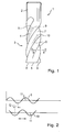
- a cutter 1 has a cylindrical tool shank 2, which with his, in the FIG. 1 upper end is clamped in a milling machine, not shown here.
- the adjoining the smooth cylindrical tool shank 2 area of the milling cutter 1 is the actual milling area 3, in this case with four angularly along the circumference of the cutter 90 degrees offset milling surfaces 4, which are located in the periphery of the milling cutter 1 and band-shaped from a the clamping end of the tool shank 2 opposite end face 5 each extend in a helical gear in the direction of the upper end of the milling section 3.
- the Milling surfaces 4 have at their edge in each case a cutting edge 6.
- each hollow, in cross-section approximately C-shaped chip removal grooves 7 are located, via which the resulting chip during chip removal is dissipated.
- the milling surfaces 4 terminate in the end face 5 of the milling cutter 1 in each case in a cutting edge 8.
- the milling surfaces 4 located in the circumferential direction are provided with a serration 9 indicated here only by transverse lines.
- This serrated edge can be varied, runs z. B. according to FIG. 2 along a sinusoid. Other courses are of course possible.
- This serration 10 may also have a continuous sinusoidal shape as shown in FIG FIG. 2 is shown.
- the periods of the sinusoidal waveform of the two serrations 9 and 10 are the same; also the height 11 of the amplitudes can be the same.
- the two serrations 9 and 10 are set so that usually no mountain of the outer serration 9 coincides with a mountain of the inner serration 10.
- the periods of the two serrations are the same as in FIG. 2 9 and 10 each have an offset 12. This offset is selected according to the workpiece to be machined and usually corresponds to 50% of the half-period of the serrations.
Landscapes
- Engineering & Computer Science (AREA)
- Mechanical Engineering (AREA)
- Milling Processes (AREA)
Abstract
Description
- Die Erfindung bezieht sich auf einen Fräser zum spanabhebenden Bearbeiten von Werkstücken, insbesondere zum Schruppen von solchen Werkstücken.
- Ein solcher Fräser weist einen zylindrischen Werkzeugschaft auf, der ein oberes Einspannende zum Einspannen des Fräsers in eine Fräsmaschine und einen sich daran anschliessenden Fräsbereich aufweist.
- Der Fräsbereich weist z.B. gemäss der
DE 20 2007 011 301 U1 eine etwa bandförmige Fräsfläche auf, die im Umfang des Schafts gelegen ist, sich in einem Schraubengang mit einem gegenüber der Mitte-Längsachse des Fräsers angestellten Steigungswinkel erstreckt und an ihrem Rand durch eine Schneidkante begrenzt ist. - An die Schneidkante schliesst sich eine längs des Schraubengangs laufende, im Längsschnitt des Fräsers nach innen gewandte, im Querschnitt etwa C-förmige, kehlförmige Freifläche als Spanabführ-Rille an.
- Die bandförmige Fräsfläche ist in ihrer Längsrichtung z.B. mit einem Wellenschliff versehen, sodass der Fräser als Schruppfräser dient. Der Wellenschliff ist z.B. ein kontinuierlicher Wellenschliff nach Art einer Sinuslinie.
- Es gab Überlegungen, den Wellenschliff als ansteigende Flanke mit einer Bergspitze und anschliessendem Tal, sozusagen mit einem "Dreiecks-Schliff" auszubilden.
- Bei dem Fräser gemäss der erwähnten
DE 20 2007 011 301 weist die Schneidkante des Fräsers noch eine Nebenschneide auf, die im Wesentlichen durch ein Entfernen der Spitze der Schneidkante durch einen schrägen Schnitt ausgebildet ist. Mit einer solchen Ausführung können die abgefrästen Späne abgeführt werden, ohne dass der Fräser mechanisch stark belastet wird. Ausserdem brechen die Späne dadurch früher, sodass sie insgesamt kürzer werden und ohne Probleme abgeführt werden. - In der
DE 20 2007 015 742 U1 ist ein Fräser beschrieben, bei dem zumindest ein Teil der sich an die Schneidkante anschliessenden Freifläche mit einer Schruppverzahnung versehen ist, die von der Schneidkante ausgeht und sich, in Umfangsrichtung des Fräsers gesehen, über zumindest einen Teil der jeweiligen Spanabführ-Rille in der Freifläche erstreckt. - Hierbei ist vorgesehen, dass diese "innen" liegende Schruppverzahnung ebenfalls als Wellenschliff aus abwechselnd Bergen und Tälern ausgebildet ist.
- Ein Vorteil einer solchen innen liegenden Schruppverzahnung, in Form z.B. eines Wellenschliffs ist, dass die Späne des jeweils bearbeiteten Werkstückes sehr kurz sind und zunächst nach unten weg von der Schneide des Fräsers tief in die Spanabführ-Rille abgeführt und dann nach oben in Richtung auf das Einspann-Ende des Fräsers umgelenkt werden. Dadurch werden sogenannte Spanklemmer zuverlässig vermieden.
- Es ist vorgeschlagen worden, einen Fräser zu gestalten, der beide Wellenschliffe miteinander kombiniert, d.h. einen direkt in der bandförmigen Fräsfläche gelegenen "äusseren" Wellenschliff und einen sich an die Schneidkante des Fräsers anschliessenden in der Spanabführ-Rille gelegenen "inneren" Wellenschliff.
- Bei diesem Vorschlag bei der Herstellung des Fräsers sind die Perioden der beiden Wellenschliffe gleich; ausserdem werden die Wellenschliffe so ausgestaltet, dass Berge und Täler des inneren und äusseren Wellschliffs jeweils gleich liegen.
- Es hat sich gezeigt, dass durch diesen "doppelten" Wellenschliff zwar eine Verbesserung der spanabhebenden Wirkung erzielt wird. Wenn Werkstücke mit einer relativ grossen Dicke parallel zur Längsachse des Fräsers gefräst werden, werden die Späne des Werkstückes jedoch relativ lang, sodass sich in den Spanabführ-Rillen manchmal Staus bilden. Der Erfindung liegt die Aufgabe zugrunde, einen Fräser anzugeben, mit dem Späne auch bei relativ dicken Werkstücken mit sehr kurzer Länge erreicht werden, sodass Staus in den Spanabführ-Rillen oder gar Spanklemmer beim Fräsen vermieden werden.
- Diese Aufgabe ist gemäss der Erfindung durch die Merkmale des Anspruchs 1 gelöst.
- Demnach bezieht sich die Erfindung auf einen Fräser zum Span abhebenden Bearbeiten von Werkstücken mit zumindest einer etwa bandförmigen Fräsfläche, die in einem Schraubengang um den Umfang des Fräsers verläuft, und einer, sich an die Schneidkante dieser Fräsfläche anschliessenden nach innen gewandten kehlfömigen Freifläche als Spanabführ-Rille.
- Die bandförmige Fräsfläche ist mit einem "äusseren" Wellenschliff versehen.
- Die Spanabführ-Rille ist in dem sich an die Schneidkante bandförmig anschliessenden Bereich mit einem "inneren" Wellenschliff versehen.
- Gemäss der Erfindung sind die Perioden der beiden Wellenschliffe so eingestellt, dass Berge und Täler der beiden Wellenschliffe nicht zusammenfallen.
- Auf diese Weise werden die abgefrästen Späne eines Werkstückes durch den jeweilig anderen Wellenschliff bei der Bearbeitung verkürzt. Ein Stau in den Spanabführ-Rillen oder Spanklemmer werden vermieden. Dass Berge und Täler der beiden Wellenschliffe nicht zusammen fallen, kann auf unterschiedliche Weise erreicht werden, z.B. dadurch, dass die Perioden der beiden Wellenschliffe unterschiedlich sind.
- Gemäss einer bevorzugten Ausführungsform der Erfindung sind die Perioden des äusseren und des inneren Wellenschliffs annähernd gleich, aber lokal im Umfang des Fräsers gegeneinander versetzt. Durch diesen Versatz trifft ein Berg des ersten Wellenschliffs nicht auf einen Berg des zweiten Wellenschliffs.
- Der Versatz der Perioden der Wellenschliffe kann 10-90% der Periodenlänge betragen. Es hat sich herausgestellt, dass je nach dem zu bearbeitenden Material des Werkstücks dieser Versatz unterschiedlich eingestellt werden sollte, um ein optimales Ergebnis zu erlangen.
- Für die meisten zu bearbeitenden Materialien beträgt dieser Versatz etwa 50% der Periodenlänge der beiden Wellenschliffe, sodass auf einen Berg des ersten, äusseren Wellenschliffs ein Tal des zweiten, inneren Wellenschliffs trifft.
- Bei der Herstellung solcher Fräser gemäss der Erfindung ist bevorzugt der Amplitudenverlauf der beiden Wellenschliffe etwa gleich, wobei auch die Amplituden dieser Wellenschliffe gleich sind. Auch hierbei sind je nach Material des zu bearbeitenden Werkstückes ggf. vorherige Untersuchungen notwendig.
- Weitere Ausgestaltungen der Erfindung gehen aus den Unteransprüchen hervor.
- Die Erfindung ist in einem Ausführungsbeispiel anhand der Zeichnung näher erläutert.
- In der Zeichnung stellen dar:
-
Figur 1 : Eine Ansicht eines Fräsers gemäss der Erfindung mit vier schraubenförmig verlaufenden Fräsflächen, die jeweils eine Schneidkante aufweisen, wobei ein äusserer und ein innerer Wellenschliff vorgesehen sind; und -
Figur 2 : eine Ansicht des schematischen Verlaufs von äusserem und inneren Wellenschliff. - Ein Fräser 1 weist einen zylindrischen Werkzeugschaft 2 auf, der mit seinem, in der
Figur 1 oberen Ende in eine hier nicht gezeigte Fräsmaschine eingespannt wird. Der sich an den glatten zylindrischen Werkzeugschaft 2 anschliessende Bereich des Fräsers 1 ist der eigentliche Fräsbereich 3, in diesem Falle mit vier jeweils winkelmässig längs des Umfanges des Fräsers um 90 Grad versetzten Fräsflächen 4, die im Umfang des Fräsers 1 gelegen sind und sich bandförmig von einer dem Einspannende des Werkzeugschafts 2 gegenüber liegenden Stirnseite 5 jeweils in einem Schraubengang in Richtung auf das obere Ende des Fräsbereichs 3 erstrecken. Die Fräsflächen 4 weisen an ihrem Rand jeweils eine Schneidkante 6 auf. Zwischen benachbarten Fräsflächen 4 sind jeweils hohle, im Querschnitt etwa C-förmige Spanabführ-Rillen 7 gelegen, über die das beim Fräsen anfallende Spangut abgeführt wird. Die Fräsflächen 4 enden in der Stirnseite 5 des Fräsers 1 jeweils in einer Schneide 8. - Die in Umfangsrichtung gelegenen Fräsflächen 4 sind mit einem hier nur durch Querstriche angedeuteten Wellenschliff 9 versehen. Dieser Wellenschliff kann vielfältig gestaltet sein, verläuft z. B. gemäss
Figur 2 längs einer Sinuskurve. Andere Verläufe sind natürlich möglich. - An die Schneidkante 6 schliesst sich in der Spanabführ-Rille 7 unmittelbar ein weiterer innerer Wellenschliff 10 an. Dieser Wellenschliff 10 kann ebenfalls einen kontinuierlichen Sinusverlauf haben, wie dies in
Figur 2 dargestellt ist. - Bei diesem Beispiel sind die Perioden des Sinusverlaufs der beiden Wellenschliffe 9 und 10 gleich; auch die Höhe 11 der Amplituden kann gleich sein.
- Entscheidend aber ist, dass die beiden Wellenschliffe 9 und 10 so eingestellt sind, dass in der Regel kein Berg des äusseren Wellenschliffes 9 mit einem Berg des inneren Wellenschliffes 10 zusammenfällt. Im Falle, dass die Perioden der beiden Wellenschliffe gleich sind, wie in
Figur 2 gezeigt, haben die Verläufe der Wellenschliffe 9 und 10 jeweils einen Versatz 12. Dieser Versatz wird entsprechend des zu bearbeitenden Werkstückes gewählt und entspricht in der Regel 50% der Halbperiode der Wellenschliffe.
Claims (7)
- Fräser (1) zum spanabhebenden Bearbeiten von Werkstücken, bestehend aus einem zylindrischen Werkzeugschaft (2), der ein oberes Einspannende zum Einspannen des Fräsers in eine Fräsmaschine und einen sich daran anschliessenden Fräsbereich (3) aufweist, mit folgenden Merkmalen:Der Fräsbereich (3) weist zumindest eine etwa bandförmige Fräsfläche (4) auf, die im Umfang des Werkzeugschafts (2) gelegen ist, sich in einem Schraubengang mit einem gegenüber der MittelLängsachse des Fräsers angestellten Steigungswinkel erstreckt und an ihrem Rand durch eine Schneidkante (6) begrenzt ist;An die Schneidkante (6) schliesst sich längs des Schraubengangs eine im Querschnitt nach innen gewandte etwa C-förmige kehlförmige Freifläche als Spanabführ-Rille (7) an;Jede bandförmige Fräsfläche (4) ist in ihrer Längsrichtung mit einem Wellenschliff (9) aus periodisch abwechselnden Bergen und Tälern versehen (erster "äusserer" Wellenschliff);Jede Fläche der Spanabführ-Rille (7) ist im Anschluss an die Schneidkante (6) ebenfalls mit einem Wellenschliff (10) aus periodisch abwechselnden Bergen und Tälern versehen (zweiter "innerer" Wellenschliff);Die Perioden der beiden Wellenschliffe (9,10) sind so eingestellt, dass Berge und Täler der beiden Wellenschliffe in der Regel nicht zusammenfallen.
- Fräser nach Anspruch 1, dadurch gekennzeichnet, dass die Perioden des ersten und des zweiten Wellenschliffs annähernd gleich sind, aber lokal im Umfang des Fräsers gegeneinander um einen Versatz (12) versetzt sind, sodass ein Berg des ersten Wellenschliffs (9) nicht auf einen Berg des zweiten Wellenschliffs (10) trifft.
- Fräser nach Anspruch 2, dadurch gekennzeichnet, dass der Versatz (12) der Perioden der Wellenschliffe (10,11) 10 bis 90 % der Periodenlänge beträgt.
- Fräser nach Anspruch 3, dadurch gekennzeichnet, dass der Versatz (12) etwa 50 % der Periodenlänge beträgt, sodass auf einen Berg des ersten Wellenschliffs (9) ein Tal des zweiten Wellenschliffs (10) trifft.
- Fräser nach einem der vorhergehenden Ansprüche, dadurch gekennzeichnet, dass der Amplitudenverlauf der beiden Wellenschliffe (9,10) etwa gleich ist.
- Fräser nach Anspruch 5, dadurch gekennzeichnet, dass die Amplituden (11) der beiden Wellenschliffe (9,10) etwa gleich sind.
- Fräser nach einem der vorhergehenden Ansprüche, dadurch gekennzeichnet, dass die Perioden des ersten und des zweiten Wellenschliffs (9,10) nicht gleich sind.
Applications Claiming Priority (1)
| Application Number | Priority Date | Filing Date | Title |
|---|---|---|---|
| DE202018000764.1U DE202018000764U1 (de) | 2018-02-15 | 2018-02-15 | Fräser zum spanabhebenden Bearbeiten von Werkstücken |
Publications (3)
| Publication Number | Publication Date |
|---|---|
| EP3527313A1 true EP3527313A1 (de) | 2019-08-21 |
| EP3527313B1 EP3527313B1 (de) | 2020-11-04 |
| EP3527313B8 EP3527313B8 (de) | 2021-02-24 |
Family
ID=61695756
Family Applications (1)
| Application Number | Title | Priority Date | Filing Date |
|---|---|---|---|
| EP19000076.0A Active EP3527313B8 (de) | 2018-02-15 | 2019-02-11 | Fräser zum spanabhebenden bearbeiten von werkstücken |
Country Status (2)
| Country | Link |
|---|---|
| EP (1) | EP3527313B8 (de) |
| DE (1) | DE202018000764U1 (de) |
Families Citing this family (2)
| Publication number | Priority date | Publication date | Assignee | Title |
|---|---|---|---|---|
| DE102021122033A1 (de) | 2021-08-25 | 2023-03-02 | Andreas Vratny | Universell einsetzbares Fräswerkzeug |
| US12350745B2 (en) * | 2023-02-01 | 2025-07-08 | Sumitomo Electric Hardmetal Corp. | Cutting tool |
Citations (6)
| Publication number | Priority date | Publication date | Assignee | Title |
|---|---|---|---|---|
| FR1226327A (fr) * | 1959-06-05 | 1960-07-11 | Fraises d'ébauche à denture redressée, et les procédés et dispositions se rattachant à l'obtention de ces fraises | |
| CH534561A (de) * | 1969-05-08 | 1973-03-15 | Weldon Tool Co | Fräser |
| JPS5255067A (en) * | 1975-10-30 | 1977-05-06 | Kobe Steel Ltd | Coarse milling cutter |
| DE202007011301U1 (de) | 2007-08-13 | 2007-12-20 | Hofmann & Vratny Ohg | Fräser |
| DE202007015742U1 (de) | 2007-11-12 | 2008-02-21 | Hofmann & Vratny Ohg | Fräser |
| WO2008028462A1 (de) * | 2006-09-05 | 2008-03-13 | Hofmann & Vratny Ohg | Schruppfräser |
-
2018
- 2018-02-15 DE DE202018000764.1U patent/DE202018000764U1/de not_active Expired - Lifetime
-
2019
- 2019-02-11 EP EP19000076.0A patent/EP3527313B8/de active Active
Patent Citations (6)
| Publication number | Priority date | Publication date | Assignee | Title |
|---|---|---|---|---|
| FR1226327A (fr) * | 1959-06-05 | 1960-07-11 | Fraises d'ébauche à denture redressée, et les procédés et dispositions se rattachant à l'obtention de ces fraises | |
| CH534561A (de) * | 1969-05-08 | 1973-03-15 | Weldon Tool Co | Fräser |
| JPS5255067A (en) * | 1975-10-30 | 1977-05-06 | Kobe Steel Ltd | Coarse milling cutter |
| WO2008028462A1 (de) * | 2006-09-05 | 2008-03-13 | Hofmann & Vratny Ohg | Schruppfräser |
| DE202007011301U1 (de) | 2007-08-13 | 2007-12-20 | Hofmann & Vratny Ohg | Fräser |
| DE202007015742U1 (de) | 2007-11-12 | 2008-02-21 | Hofmann & Vratny Ohg | Fräser |
Also Published As
| Publication number | Publication date |
|---|---|
| EP3527313B1 (de) | 2020-11-04 |
| EP3527313B8 (de) | 2021-02-24 |
| DE202018000764U1 (de) | 2018-03-01 |
Similar Documents
| Publication | Publication Date | Title |
|---|---|---|
| EP0758279B1 (de) | Werkzeug für die spanende bearbeitung | |
| EP1864737A2 (de) | Spanabhebendes Werkzeug | |
| EP2078574B1 (de) | Schruppfräser mit abgeschrägter Schneidkante | |
| DE102012018845B4 (de) | Fräser zum Schneiden einer Neunzig-Grad-Schulter in ein Werkstück | |
| EP0980297A1 (de) | Schneideinsatz für die spanabhebende bearbeitung | |
| WO2010102992A1 (de) | Vorrichtung und verfahren zum fertigen eines kegelrades, insbesondere eines kronenrades | |
| DE202007002120U1 (de) | Gesteinsbohrer | |
| EP3527313B1 (de) | Fräser zum spanabhebenden bearbeiten von werkstücken | |
| DE3334165A1 (de) | Schneidvorrichtung fuer wabenfoermige leichtbaukoerper | |
| DE7909735U1 (de) | Selbstbohrende Schraube | |
| WO2008028462A1 (de) | Schruppfräser | |
| EP3031560A1 (de) | Bearbeitungswerkzeug und schneidplatte für das bearbeitungswerkzeug | |
| EP2058074A1 (de) | Fräser | |
| AT511339B1 (de) | Verfahren und vorrichtung zur bearbeitung von längskanten von metallischen werkstücken | |
| DE3209821A1 (de) | Wendeplattenfraeser | |
| EP2915613B1 (de) | Querlochsenker | |
| EP3093089A1 (de) | Rotationswerkzeug | |
| DE112011100157T5 (de) | Werkzeug | |
| DE2916809A1 (de) | Spanabhebendes werkzeug fuer metallbearbeitung | |
| DE2414635B2 (de) | Spanlos-Gewindeformer | |
| DE1146330B (de) | Stirnmesserkopf fuer Verzahnungsmaschinen | |
| DE102016109452A1 (de) | Schneidplatte für ein Fräswerkzeug und Fräswerkzeug | |
| DE102015200753A1 (de) | Werkzeug zum Herstellen eines Gewindes | |
| DE10144735B4 (de) | Schneideinsätze und Rotations-Umfangsfräser mit austauschbaren Schneideinsätzen | |
| DE102013222206A1 (de) | Werkzeug zur spanenden Bearbeitung von Werkstückoberflächen |
Legal Events
| Date | Code | Title | Description |
|---|---|---|---|
| PUAI | Public reference made under article 153(3) epc to a published international application that has entered the european phase |
Free format text: ORIGINAL CODE: 0009012 |
|
| STAA | Information on the status of an ep patent application or granted ep patent |
Free format text: STATUS: THE APPLICATION HAS BEEN PUBLISHED |
|
| AK | Designated contracting states |
Kind code of ref document: A1 Designated state(s): AL AT BE BG CH CY CZ DE DK EE ES FI FR GB GR HR HU IE IS IT LI LT LU LV MC MK MT NL NO PL PT RO RS SE SI SK SM TR |
|
| AX | Request for extension of the european patent |
Extension state: BA ME |
|
| STAA | Information on the status of an ep patent application or granted ep patent |
Free format text: STATUS: REQUEST FOR EXAMINATION WAS MADE |
|
| 17P | Request for examination filed |
Effective date: 20190912 |
|
| GRAP | Despatch of communication of intention to grant a patent |
Free format text: ORIGINAL CODE: EPIDOSNIGR1 |
|
| STAA | Information on the status of an ep patent application or granted ep patent |
Free format text: STATUS: GRANT OF PATENT IS INTENDED |
|
| INTG | Intention to grant announced |
Effective date: 20200731 |
|
| GRAS | Grant fee paid |
Free format text: ORIGINAL CODE: EPIDOSNIGR3 |
|
| GRAA | (expected) grant |
Free format text: ORIGINAL CODE: 0009210 |
|
| STAA | Information on the status of an ep patent application or granted ep patent |
Free format text: STATUS: THE PATENT HAS BEEN GRANTED |
|
| AK | Designated contracting states |
Kind code of ref document: B1 Designated state(s): AL AT BE BG CH CY CZ DE DK EE ES FI FR GB GR HR HU IE IS IT LI LT LU LV MC MK MT NL NO PL PT RO RS SE SI SK SM TR |
|
| REG | Reference to a national code |
Ref country code: GB Ref legal event code: FG4D Free format text: NOT ENGLISH |
|
| REG | Reference to a national code |
Ref country code: CH Ref legal event code: EP |
|
| REG | Reference to a national code |
Ref country code: AT Ref legal event code: REF Ref document number: 1330154 Country of ref document: AT Kind code of ref document: T Effective date: 20201115 |
|
| GRAT | Correction requested after decision to grant or after decision to maintain patent in amended form |
Free format text: ORIGINAL CODE: EPIDOSNCDEC |
|
| REG | Reference to a national code |
Ref country code: IE Ref legal event code: FG4D Free format text: LANGUAGE OF EP DOCUMENT: GERMAN |
|
| REG | Reference to a national code |
Ref country code: DE Ref legal event code: R096 Ref document number: 502019000346 Country of ref document: DE |
|
| REG | Reference to a national code |
Ref country code: CH Ref legal event code: PK Free format text: BERICHTIGUNGEN |
|
| RIN2 | Information on inventor provided after grant (corrected) |
Inventor name: VRATNY, ZDENEK |
|
| REG | Reference to a national code |
Ref country code: CH Ref legal event code: PK Free format text: BERICHTIGUNG B8 |
|
| REG | Reference to a national code |
Ref country code: NL Ref legal event code: MP Effective date: 20201104 |
|
| REG | Reference to a national code |
Ref country code: CH Ref legal event code: NV Representative=s name: FREI PATENTANWALTSBUERO AG, CH |
|
| PG25 | Lapsed in a contracting state [announced via postgrant information from national office to epo] |
Ref country code: FI Free format text: LAPSE BECAUSE OF FAILURE TO SUBMIT A TRANSLATION OF THE DESCRIPTION OR TO PAY THE FEE WITHIN THE PRESCRIBED TIME-LIMIT Effective date: 20201104 Ref country code: PT Free format text: LAPSE BECAUSE OF FAILURE TO SUBMIT A TRANSLATION OF THE DESCRIPTION OR TO PAY THE FEE WITHIN THE PRESCRIBED TIME-LIMIT Effective date: 20210304 Ref country code: RS Free format text: LAPSE BECAUSE OF FAILURE TO SUBMIT A TRANSLATION OF THE DESCRIPTION OR TO PAY THE FEE WITHIN THE PRESCRIBED TIME-LIMIT Effective date: 20201104 Ref country code: NO Free format text: LAPSE BECAUSE OF FAILURE TO SUBMIT A TRANSLATION OF THE DESCRIPTION OR TO PAY THE FEE WITHIN THE PRESCRIBED TIME-LIMIT Effective date: 20210204 Ref country code: GR Free format text: LAPSE BECAUSE OF FAILURE TO SUBMIT A TRANSLATION OF THE DESCRIPTION OR TO PAY THE FEE WITHIN THE PRESCRIBED TIME-LIMIT Effective date: 20210205 |
|
| PG25 | Lapsed in a contracting state [announced via postgrant information from national office to epo] |
Ref country code: BG Free format text: LAPSE BECAUSE OF FAILURE TO SUBMIT A TRANSLATION OF THE DESCRIPTION OR TO PAY THE FEE WITHIN THE PRESCRIBED TIME-LIMIT Effective date: 20210204 Ref country code: LV Free format text: LAPSE BECAUSE OF FAILURE TO SUBMIT A TRANSLATION OF THE DESCRIPTION OR TO PAY THE FEE WITHIN THE PRESCRIBED TIME-LIMIT Effective date: 20201104 Ref country code: IS Free format text: LAPSE BECAUSE OF FAILURE TO SUBMIT A TRANSLATION OF THE DESCRIPTION OR TO PAY THE FEE WITHIN THE PRESCRIBED TIME-LIMIT Effective date: 20210304 Ref country code: PL Free format text: LAPSE BECAUSE OF FAILURE TO SUBMIT A TRANSLATION OF THE DESCRIPTION OR TO PAY THE FEE WITHIN THE PRESCRIBED TIME-LIMIT Effective date: 20201104 Ref country code: SE Free format text: LAPSE BECAUSE OF FAILURE TO SUBMIT A TRANSLATION OF THE DESCRIPTION OR TO PAY THE FEE WITHIN THE PRESCRIBED TIME-LIMIT Effective date: 20201104 Ref country code: ES Free format text: LAPSE BECAUSE OF FAILURE TO SUBMIT A TRANSLATION OF THE DESCRIPTION OR TO PAY THE FEE WITHIN THE PRESCRIBED TIME-LIMIT Effective date: 20201104 |
|
| REG | Reference to a national code |
Ref country code: LT Ref legal event code: MG9D |
|
| PG25 | Lapsed in a contracting state [announced via postgrant information from national office to epo] |
Ref country code: HR Free format text: LAPSE BECAUSE OF FAILURE TO SUBMIT A TRANSLATION OF THE DESCRIPTION OR TO PAY THE FEE WITHIN THE PRESCRIBED TIME-LIMIT Effective date: 20201104 |
|
| PG25 | Lapsed in a contracting state [announced via postgrant information from national office to epo] |
Ref country code: SM Free format text: LAPSE BECAUSE OF FAILURE TO SUBMIT A TRANSLATION OF THE DESCRIPTION OR TO PAY THE FEE WITHIN THE PRESCRIBED TIME-LIMIT Effective date: 20201104 Ref country code: SK Free format text: LAPSE BECAUSE OF FAILURE TO SUBMIT A TRANSLATION OF THE DESCRIPTION OR TO PAY THE FEE WITHIN THE PRESCRIBED TIME-LIMIT Effective date: 20201104 Ref country code: CZ Free format text: LAPSE BECAUSE OF FAILURE TO SUBMIT A TRANSLATION OF THE DESCRIPTION OR TO PAY THE FEE WITHIN THE PRESCRIBED TIME-LIMIT Effective date: 20201104 Ref country code: EE Free format text: LAPSE BECAUSE OF FAILURE TO SUBMIT A TRANSLATION OF THE DESCRIPTION OR TO PAY THE FEE WITHIN THE PRESCRIBED TIME-LIMIT Effective date: 20201104 Ref country code: LT Free format text: LAPSE BECAUSE OF FAILURE TO SUBMIT A TRANSLATION OF THE DESCRIPTION OR TO PAY THE FEE WITHIN THE PRESCRIBED TIME-LIMIT Effective date: 20201104 Ref country code: RO Free format text: LAPSE BECAUSE OF FAILURE TO SUBMIT A TRANSLATION OF THE DESCRIPTION OR TO PAY THE FEE WITHIN THE PRESCRIBED TIME-LIMIT Effective date: 20201104 |
|
| REG | Reference to a national code |
Ref country code: DE Ref legal event code: R097 Ref document number: 502019000346 Country of ref document: DE |
|
| PG25 | Lapsed in a contracting state [announced via postgrant information from national office to epo] |
Ref country code: DK Free format text: LAPSE BECAUSE OF FAILURE TO SUBMIT A TRANSLATION OF THE DESCRIPTION OR TO PAY THE FEE WITHIN THE PRESCRIBED TIME-LIMIT Effective date: 20201104 |
|
| PLBE | No opposition filed within time limit |
Free format text: ORIGINAL CODE: 0009261 |
|
| STAA | Information on the status of an ep patent application or granted ep patent |
Free format text: STATUS: NO OPPOSITION FILED WITHIN TIME LIMIT |
|
| PG25 | Lapsed in a contracting state [announced via postgrant information from national office to epo] |
Ref country code: MC Free format text: LAPSE BECAUSE OF FAILURE TO SUBMIT A TRANSLATION OF THE DESCRIPTION OR TO PAY THE FEE WITHIN THE PRESCRIBED TIME-LIMIT Effective date: 20201104 |
|
| 26N | No opposition filed |
Effective date: 20210805 |
|
| REG | Reference to a national code |
Ref country code: BE Ref legal event code: MM Effective date: 20210228 |
|
| PG25 | Lapsed in a contracting state [announced via postgrant information from national office to epo] |
Ref country code: LU Free format text: LAPSE BECAUSE OF NON-PAYMENT OF DUE FEES Effective date: 20210211 Ref country code: AL Free format text: LAPSE BECAUSE OF FAILURE TO SUBMIT A TRANSLATION OF THE DESCRIPTION OR TO PAY THE FEE WITHIN THE PRESCRIBED TIME-LIMIT Effective date: 20201104 Ref country code: NL Free format text: LAPSE BECAUSE OF FAILURE TO SUBMIT A TRANSLATION OF THE DESCRIPTION OR TO PAY THE FEE WITHIN THE PRESCRIBED TIME-LIMIT Effective date: 20201104 |
|
| PG25 | Lapsed in a contracting state [announced via postgrant information from national office to epo] |
Ref country code: SI Free format text: LAPSE BECAUSE OF FAILURE TO SUBMIT A TRANSLATION OF THE DESCRIPTION OR TO PAY THE FEE WITHIN THE PRESCRIBED TIME-LIMIT Effective date: 20201104 |
|
| PG25 | Lapsed in a contracting state [announced via postgrant information from national office to epo] |
Ref country code: IE Free format text: LAPSE BECAUSE OF NON-PAYMENT OF DUE FEES Effective date: 20210211 |
|
| PG25 | Lapsed in a contracting state [announced via postgrant information from national office to epo] |
Ref country code: IS Free format text: LAPSE BECAUSE OF FAILURE TO SUBMIT A TRANSLATION OF THE DESCRIPTION OR TO PAY THE FEE WITHIN THE PRESCRIBED TIME-LIMIT Effective date: 20210304 |
|
| PG25 | Lapsed in a contracting state [announced via postgrant information from national office to epo] |
Ref country code: BE Free format text: LAPSE BECAUSE OF NON-PAYMENT OF DUE FEES Effective date: 20210228 |
|
| PG25 | Lapsed in a contracting state [announced via postgrant information from national office to epo] |
Ref country code: CY Free format text: LAPSE BECAUSE OF FAILURE TO SUBMIT A TRANSLATION OF THE DESCRIPTION OR TO PAY THE FEE WITHIN THE PRESCRIBED TIME-LIMIT Effective date: 20201104 |
|
| PG25 | Lapsed in a contracting state [announced via postgrant information from national office to epo] |
Ref country code: HU Free format text: LAPSE BECAUSE OF FAILURE TO SUBMIT A TRANSLATION OF THE DESCRIPTION OR TO PAY THE FEE WITHIN THE PRESCRIBED TIME-LIMIT; INVALID AB INITIO Effective date: 20190211 |
|
| GBPC | Gb: european patent ceased through non-payment of renewal fee |
Effective date: 20230211 |
|
| PG25 | Lapsed in a contracting state [announced via postgrant information from national office to epo] |
Ref country code: GB Free format text: LAPSE BECAUSE OF NON-PAYMENT OF DUE FEES Effective date: 20230211 |
|
| PG25 | Lapsed in a contracting state [announced via postgrant information from national office to epo] |
Ref country code: GB Free format text: LAPSE BECAUSE OF NON-PAYMENT OF DUE FEES Effective date: 20230211 |
|
| PG25 | Lapsed in a contracting state [announced via postgrant information from national office to epo] |
Ref country code: MK Free format text: LAPSE BECAUSE OF FAILURE TO SUBMIT A TRANSLATION OF THE DESCRIPTION OR TO PAY THE FEE WITHIN THE PRESCRIBED TIME-LIMIT Effective date: 20201104 |
|
| PG25 | Lapsed in a contracting state [announced via postgrant information from national office to epo] |
Ref country code: MT Free format text: LAPSE BECAUSE OF FAILURE TO SUBMIT A TRANSLATION OF THE DESCRIPTION OR TO PAY THE FEE WITHIN THE PRESCRIBED TIME-LIMIT Effective date: 20201104 |
|
| REG | Reference to a national code |
Ref country code: DE Ref legal event code: R082 Ref document number: 502019000346 Country of ref document: DE Representative=s name: BECKORD & NIEDLICH PATENTANWAELTE PARTG MBB, DE |
|
| PG25 | Lapsed in a contracting state [announced via postgrant information from national office to epo] |
Ref country code: TR Free format text: LAPSE BECAUSE OF FAILURE TO SUBMIT A TRANSLATION OF THE DESCRIPTION OR TO PAY THE FEE WITHIN THE PRESCRIBED TIME-LIMIT Effective date: 20201104 |
|
| REG | Reference to a national code |
Ref country code: CH Ref legal event code: U11 Free format text: ST27 STATUS EVENT CODE: U-0-0-U10-U11 (AS PROVIDED BY THE NATIONAL OFFICE) Effective date: 20260301 |
|
| PGFP | Annual fee paid to national office [announced via postgrant information from national office to epo] |
Ref country code: DE Payment date: 20260228 Year of fee payment: 8 |
|
| PGFP | Annual fee paid to national office [announced via postgrant information from national office to epo] |
Ref country code: AT Payment date: 20260219 Year of fee payment: 8 |
|
| PGFP | Annual fee paid to national office [announced via postgrant information from national office to epo] |
Ref country code: IT Payment date: 20260224 Year of fee payment: 8 |
|
| PGFP | Annual fee paid to national office [announced via postgrant information from national office to epo] |
Ref country code: FR Payment date: 20260218 Year of fee payment: 8 |
|
| PGFP | Annual fee paid to national office [announced via postgrant information from national office to epo] |
Ref country code: CH Payment date: 20260301 Year of fee payment: 8 |