EP3525945B1 - Schrägwalzwerk - Google Patents
Schrägwalzwerk Download PDFInfo
- Publication number
- EP3525945B1 EP3525945B1 EP17781472.0A EP17781472A EP3525945B1 EP 3525945 B1 EP3525945 B1 EP 3525945B1 EP 17781472 A EP17781472 A EP 17781472A EP 3525945 B1 EP3525945 B1 EP 3525945B1
- Authority
- EP
- European Patent Office
- Prior art keywords
- cross
- roll
- rolling mill
- roller
- rolling
- Prior art date
- Legal status (The legal status is an assumption and is not a legal conclusion. Google has not performed a legal analysis and makes no representation as to the accuracy of the status listed.)
- Active
Links
Images
Classifications
-
- B—PERFORMING OPERATIONS; TRANSPORTING
- B21—MECHANICAL METAL-WORKING WITHOUT ESSENTIALLY REMOVING MATERIAL; PUNCHING METAL
- B21B—ROLLING OF METAL
- B21B19/00—Tube-rolling by rollers arranged outside the work and having their axes not perpendicular to the axis of the work
- B21B19/02—Tube-rolling by rollers arranged outside the work and having their axes not perpendicular to the axis of the work the axes of the rollers being arranged essentially diagonally to the axis of the work, e.g. "cross" tube-rolling ; Diescher mills, Stiefel disc piercers or Stiefel rotary piercers
- B21B19/06—Rolling hollow basic material, e.g. Assel mills
-
- B—PERFORMING OPERATIONS; TRANSPORTING
- B21—MECHANICAL METAL-WORKING WITHOUT ESSENTIALLY REMOVING MATERIAL; PUNCHING METAL
- B21B—ROLLING OF METAL
- B21B1/00—Metal-rolling methods or mills for making semi-finished products of solid or profiled cross-section; Sequence of operations in milling trains; Layout of rolling-mill plant, e.g. grouping of stands; Succession of passes or of sectional pass alternations
- B21B1/16—Metal-rolling methods or mills for making semi-finished products of solid or profiled cross-section; Sequence of operations in milling trains; Layout of rolling-mill plant, e.g. grouping of stands; Succession of passes or of sectional pass alternations for rolling wire rods, bars, merchant bars, rounds wire or material of like small cross-section
- B21B1/20—Metal-rolling methods or mills for making semi-finished products of solid or profiled cross-section; Sequence of operations in milling trains; Layout of rolling-mill plant, e.g. grouping of stands; Succession of passes or of sectional pass alternations for rolling wire rods, bars, merchant bars, rounds wire or material of like small cross-section in a non-continuous process,(e.g. skew rolling, i.e. planetary cross rolling)
-
- B—PERFORMING OPERATIONS; TRANSPORTING
- B21—MECHANICAL METAL-WORKING WITHOUT ESSENTIALLY REMOVING MATERIAL; PUNCHING METAL
- B21B—ROLLING OF METAL
- B21B13/00—Metal-rolling stands, i.e. an assembly composed of a stand frame, rolls, and accessories
-
- B—PERFORMING OPERATIONS; TRANSPORTING
- B21—MECHANICAL METAL-WORKING WITHOUT ESSENTIALLY REMOVING MATERIAL; PUNCHING METAL
- B21B—ROLLING OF METAL
- B21B13/00—Metal-rolling stands, i.e. an assembly composed of a stand frame, rolls, and accessories
- B21B13/008—Skew rolling stands, e.g. for rolling rounds
-
- B—PERFORMING OPERATIONS; TRANSPORTING
- B21—MECHANICAL METAL-WORKING WITHOUT ESSENTIALLY REMOVING MATERIAL; PUNCHING METAL
- B21B—ROLLING OF METAL
- B21B19/00—Tube-rolling by rollers arranged outside the work and having their axes not perpendicular to the axis of the work
- B21B19/02—Tube-rolling by rollers arranged outside the work and having their axes not perpendicular to the axis of the work the axes of the rollers being arranged essentially diagonally to the axis of the work, e.g. "cross" tube-rolling ; Diescher mills, Stiefel disc piercers or Stiefel rotary piercers
- B21B19/04—Rolling basic material of solid, i.e. non-hollow, structure; Piercing, e.g. rotary piercing mills
-
- B—PERFORMING OPERATIONS; TRANSPORTING
- B21—MECHANICAL METAL-WORKING WITHOUT ESSENTIALLY REMOVING MATERIAL; PUNCHING METAL
- B21B—ROLLING OF METAL
- B21B2203/00—Auxiliary arrangements, devices or methods in combination with rolling mills or rolling methods
- B21B2203/32—Roll changing stools
-
- B—PERFORMING OPERATIONS; TRANSPORTING
- B21—MECHANICAL METAL-WORKING WITHOUT ESSENTIALLY REMOVING MATERIAL; PUNCHING METAL
- B21B—ROLLING OF METAL
- B21B31/00—Rolling stand structures; Mounting, adjusting, or interchanging rolls, roll mountings, or stand frames
- B21B31/08—Interchanging rolls, roll mountings, or stand frames, e.g. using C-hooks; Replacing roll chocks on roll shafts
- B21B31/14—Interchanging rolls, roll mountings, or stand frames, e.g. using C-hooks; Replacing roll chocks on roll shafts by pivotally displacing
Definitions
- the invention relates to a cross rolling mill according to the preamble of claim 1.
- the roll shaft can also be adjusted around two different axes.
- intermediate elements are required which increase the overall height of the employment.
- the number of roller shafts can preferably be two, three or even four.
- the cross rolling mill can work similarly according to the Assel method or at least the Assel method.
- Alignment of the roller axis around the positioning axes is meant geometrically in the sense of the invention, so that the positioning axes do not have any physical waves or Must include something similar.
- the adjusting axes can preferably each be oriented perpendicular to the roller axis, in particular also perpendicular to one another.
- an actuator can be any actuator by means of which the roller axis is adjusted.
- hydraulic cylinders or electromechanical actuators can be provided.
- the actuator can generally preferably be designed to exert the rolling force on the workpiece.
- the roller shaft has at least one rotary bearing and a pivotable pressure stilts at two opposite ends. In this way, a complete and particularly low-friction adjustable support can take place via the pivotable pressure stilts.
- roller shaft is received on a roller mill, the roller mill being mounted so as to be movable about the positioning axes and the pressure stilts being supported relative to the roller mill.
- the roller mill can be designed as a frame which is rigid in itself but can be moved relative to a frame.
- the roller mill is subjected to force by means of a preferably hydraulic tension member against the direction of the rolling force. Together with the forces of the actuators, a play-free holding of the roller in its respective position is thus achieved overall.
- the pressure stilts have at least one end with a bearing cap which can be pivoted relative to the pressure stilts. This allows a simple lateral offset of one Point of contact of the pressure stilts or the bearing cap. In addition, the bearing cap can be easily replaced as a wearing part.
- the pressure stilts can be pivoted from an neutral position in every spatial direction by an angle about a pivot point.
- roller shafts preferably at least three roller shafts, particularly preferably all of the roller shafts of the cross-rolling mill are adjustable in accordance with one of the features described above.
- the invention avoids or reduces frictional forces and transverse forces of the adjustment components. There is also the advantage of improved positioning accuracy under load. Furthermore, the vibration behavior of the adjustment system is improved and the overall rigidity is increased.
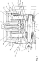
- the diagonal rolling mill shown according to the invention comprises three roller shafts 1 of identical construction, of which only one can be seen in the illustration.
- the roller shaft 1 has a roller body 2 which acts on a workpiece radially to a roller axis W or in the direction of a rolling force.
- the roller shaft 1 is rotated about the roller axis W via a cardanically articulated drive shaft 3.
- a rotary bearing 4, 5 supporting the rolling forces is arranged in front of and behind the roller body 2.
- the rotary bearings 4, 5 are in turn received and supported on a roller mill 6, the roller mill 6 being held movably relative to a frame 8 of the cross-rolling mill by means of a bearing 7.
- the roller mill can be pivotably adjusted both about a first adjusting axis S1 and about a second adjusting axis S2.
- the second positioning axis S2 follows in the illustration Fig. 1 perpendicular to the plane of the drawing.
- the positioning axes S1, S2 and the roller axis are perpendicular to each other, but do not have to intersect.
- the roller mill 6 is formed as a rigid component which is essentially yoke-shaped in cross section.
- Two support areas 6a of the roller mill hold the rotary bearings 4, 5 on the one hand and are supported on an intermediate member 9, 10 on the other hand.
- the intermediate members are arranged between the roller mill 6 or the rotary bearings 4, 5 on the one hand and in each case one of two actuators 11, 12 on the other hand.
- the roller 1 is adjusted by aligning the roller mill 6 and thus the rotary bearings 4, 5.
- the actuators 11, 12, which are designed as hydraulic cylinders, are each positioned.
- the actuators 11, 12 can also transmit the rolling force exerted on the workpiece.
- the roller mill 6 is also pulled against the rolling force by a tension member 13 designed as a hydraulic cylinder, so that the roller mill 6 is pressed firmly against the actuators at all times.
- the force of the tension member is smaller than the force of the actuators and ensures play-free positioning of the roller shaft 1 or enables the workpiece to be released.
- the intermediate elements 9, 10 are each of the same design and are used to compensate for tilting and offset movements occurring during the adjustment between the actuators 11, 12 on the one hand and the roller mill 6 or the roller shaft 1 on the other.
- the intermediate members 9, 10 each comprise a pressure stalk 14, 15.
- the pressure sticks 14, 15 can each be pivoted in several directions. This is achieved by spherical bearings of the pressure stilts 14, 15.
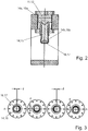
- the pressure stilts are each provided on the actuator side with a concave dome surface 14a, 15a, a corresponding convex dome surface being provided on the actuator.
- the pressure stilts are also provided with a concave spherical surface 14b, 15b.
- An essentially hemispherical spherical cap 16, 17 is inserted into the end of the plunger 14, 15. This can be pivoted with respect to the pressure stilts via the spherical surface 14b, 15b and bears against the roller mill 6 with a flat counter surface. In this way, a lateral offset of the counter surface with respect to the roller mill can also be made possible if necessary.
- domes which are curved in reverse can also be provided, for example convex domes on the pressure stilts 14, 15 and correspondingly concave domes on the actuators 14, 15 and / or the bearing domes 16, 17.
- FIG. 3 clarifies, in which a plunger 14, 15 is shown, which is pivoted in four different exemplary spatial directions by an angle up to a stop.
- a maximum lateral offset d of the counter surfaces of the bearing caps 16, 17 is made possible by the pivoting.
Landscapes
- Engineering & Computer Science (AREA)
- Mechanical Engineering (AREA)
- Rolls And Other Rotary Bodies (AREA)
- Support Of The Bearing (AREA)
- Reduction Rolling/Reduction Stand/Operation Of Reduction Machine (AREA)
- Friction Gearing (AREA)
- Crushing And Grinding (AREA)
Priority Applications (1)
| Application Number | Priority Date | Filing Date | Title |
|---|---|---|---|
| PL17781472T PL3525945T3 (pl) | 2016-10-11 | 2017-10-10 | Walcarka skośna |
Applications Claiming Priority (2)
| Application Number | Priority Date | Filing Date | Title |
|---|---|---|---|
| DE102016219723.1A DE102016219723A1 (de) | 2016-10-11 | 2016-10-11 | Schrägwalzwerk |
| PCT/EP2017/075784 WO2018069303A1 (de) | 2016-10-11 | 2017-10-10 | Schrägwalzwerk |
Publications (2)
| Publication Number | Publication Date |
|---|---|
| EP3525945A1 EP3525945A1 (de) | 2019-08-21 |
| EP3525945B1 true EP3525945B1 (de) | 2020-02-19 |
Family
ID=60051513
Family Applications (1)
| Application Number | Title | Priority Date | Filing Date |
|---|---|---|---|
| EP17781472.0A Active EP3525945B1 (de) | 2016-10-11 | 2017-10-10 | Schrägwalzwerk |
Country Status (9)
| Country | Link |
|---|---|
| US (1) | US11400498B2 (pl) |
| EP (1) | EP3525945B1 (pl) |
| JP (1) | JP6803992B2 (pl) |
| CN (1) | CN109843457B (pl) |
| DE (1) | DE102016219723A1 (pl) |
| ES (1) | ES2784391T3 (pl) |
| PL (1) | PL3525945T3 (pl) |
| RU (1) | RU2717425C1 (pl) |
| WO (1) | WO2018069303A1 (pl) |
Families Citing this family (3)
| Publication number | Priority date | Publication date | Assignee | Title |
|---|---|---|---|---|
| DE102019123836A1 (de) * | 2019-09-05 | 2021-03-11 | Sms Group Gmbh | Schrägwalzaggregat sowie Verfahren zum Anstellen des Walzkalibers eines Schrägwalzaggregats |
| CN112986854B (zh) * | 2021-02-03 | 2022-10-04 | 宇能电气有限公司 | 一种便携式航空启动电源检测设备 |
| CN113843379B (zh) * | 2021-10-26 | 2022-04-22 | 宁波大学 | 一种成形阶梯轴的三辊斜轧装置 |
Family Cites Families (16)
| Publication number | Priority date | Publication date | Assignee | Title |
|---|---|---|---|---|
| US2017374A (en) * | 1932-09-07 | 1935-10-15 | Nat Tube Co | Tube rolling mill |
| GB1289098A (pl) * | 1968-10-21 | 1972-09-13 | ||
| DE2814493C3 (de) * | 1978-03-31 | 1980-12-18 | Mannesmann Ag, 4000 Duesseldorf | Schrägwalzwerk |
| US4348952A (en) * | 1981-01-19 | 1982-09-14 | Usm Corporation | Cross axis mechanism |
| DE3406841A1 (de) * | 1984-02-23 | 1985-09-12 | Mannesmann AG, 4000 Düsseldorf | Walzenanstellung fuer ein dreiwalzen-kegelschraegwalzwerk |
| SU1251987A1 (ru) * | 1985-04-15 | 1986-08-23 | Предприятие П/Я В-2869 | Многовалкова клеть (ее варианты) |
| RU2074777C1 (ru) * | 1994-10-12 | 1997-03-10 | Акционерное общество "Череповецкий сталепрокатный завод" | Многовалковая клеть |
| JP3334771B2 (ja) * | 1995-01-23 | 2002-10-15 | 石川島播磨重工業株式会社 | 圧延機 |
| DE19510694A1 (de) * | 1995-03-14 | 1996-09-19 | Mannesmann Ag | Walzgerüst mit gekreuzten Arbeitswalzen |
| US5655398A (en) * | 1995-05-11 | 1997-08-12 | Danieli United, A Division Of Danieli Corporation | Roll crossing and shifting system |
| US5924319A (en) * | 1998-07-07 | 1999-07-20 | Danieli United | Roll crossing, offsetting, bending and shifting system for rolling mills |
| DE10030823C2 (de) * | 2000-06-23 | 2003-08-07 | Gmt Ges Fuer Metallurg Technol | 3-Walzen-Schrägwalzgerüst |
| DE10349056A1 (de) * | 2003-10-17 | 2005-05-19 | Kocks Technik Gmbh & Co. Kg | Verfahren und Vorrichtung zum Walzen von Walzgut in einer Walzanlage mit einem Schrägwalzwerk |
| CN2784100Y (zh) * | 2005-04-19 | 2006-05-31 | 江苏包罗铜材集团股份有限公司 | 三辊斜轧冷穿、冷扩孔机 |
| CN101758073B (zh) * | 2009-12-22 | 2012-06-27 | 太原重工股份有限公司 | 一种采用铸焊结构的斜轧二辊穿孔机 |
| EP3108978B1 (en) * | 2015-06-26 | 2019-02-20 | DANIELI & C. OFFICINE MECCANICHE S.p.A. | Rolling stand and rolling method |
-
2016
- 2016-10-11 DE DE102016219723.1A patent/DE102016219723A1/de not_active Withdrawn
-
2017
- 2017-10-10 US US16/341,130 patent/US11400498B2/en active Active
- 2017-10-10 CN CN201780062830.9A patent/CN109843457B/zh active Active
- 2017-10-10 WO PCT/EP2017/075784 patent/WO2018069303A1/de not_active Ceased
- 2017-10-10 ES ES17781472T patent/ES2784391T3/es active Active
- 2017-10-10 JP JP2019540699A patent/JP6803992B2/ja active Active
- 2017-10-10 EP EP17781472.0A patent/EP3525945B1/de active Active
- 2017-10-10 PL PL17781472T patent/PL3525945T3/pl unknown
- 2017-10-10 RU RU2019110213A patent/RU2717425C1/ru active
Non-Patent Citations (1)
| Title |
|---|
| None * |
Also Published As
| Publication number | Publication date |
|---|---|
| ES2784391T3 (es) | 2020-09-25 |
| PL3525945T3 (pl) | 2020-07-13 |
| RU2717425C1 (ru) | 2020-03-23 |
| DE102016219723A1 (de) | 2018-04-12 |
| CN109843457A (zh) | 2019-06-04 |
| EP3525945A1 (de) | 2019-08-21 |
| WO2018069303A1 (de) | 2018-04-19 |
| US11400498B2 (en) | 2022-08-02 |
| JP2019530582A (ja) | 2019-10-24 |
| US20200188973A1 (en) | 2020-06-18 |
| CN109843457B (zh) | 2020-10-23 |
| JP6803992B2 (ja) | 2020-12-23 |
Similar Documents
| Publication | Publication Date | Title |
|---|---|---|
| EP2049016B1 (de) | Vorrichtung mit einem direkt angetriebenen rotationskörper und einem aerostatischen lager | |
| DE4126545C2 (de) | Dreiringwälzlager für die Zapfen der Zylinder von Druckmaschinen | |
| EP1668263B1 (de) | Drehlagerung eines rotationskörpers | |
| DE2406697B2 (de) | Gelenkige verbindung zwischen einem kreuzkopf und einer stange | |
| WO2015144460A1 (de) | Gleitlagersystem | |
| EP3525945B1 (de) | Schrägwalzwerk | |
| DE69819562T2 (de) | Stützwalzenanordnung mit dynamischer balligkeitsregelung | |
| EP0447651A1 (de) | Durchbiegungseinstellwalze | |
| EP1929164B1 (de) | Breitstreckwalze | |
| DE2402101C3 (de) | Einrichtung zum Verbinden des Fonnzylinders einer Rotations-Druckmaschine mit dessen Antriebswelle | |
| EP3581291A1 (de) | Blechbiegemaschine mit veränderbarer walzengeometrie | |
| EP3308862B1 (de) | Lagerelement geeignet für die lagerung eines mahltellers in einer wälzmühle | |
| AT392661B (de) | Presswalze, deren durchbiegung einstellbar ist | |
| DE102015221762A1 (de) | Vorrichtung zum Anstellen einer Stauchwalze eines Stauchgerüsts | |
| WO2012012815A1 (de) | Walzgerüst mit walzenlagerung | |
| EP1989454B1 (de) | Walze | |
| DE3208780A1 (de) | Gelenkwelle mit richtvorrichtung | |
| EP3772598B1 (de) | Metallkäfig zur aufnahme von wälzkörpern in einem wälzlager | |
| DE102004022007B4 (de) | Lagerung für eine Walze einer Rotationsdruckmaschine, insbesondere für eine Auftragwalze eines Lackwerks | |
| EP3161197B1 (de) | Anpresseinrichtung zum anpressen eines geflechtschlauches an einen bauteilkern und flechtmaschine | |
| DE3113080C2 (de) | "Rotorkopf für Ein-Blatt-Rotor von Windenergie-Anlagen" | |
| EP3116667B1 (de) | Welle-nabe-verbindung und antriebsanordnung mit einer derartigen welle-nabe-verbindung | |
| DE2802742C2 (de) | Abziehvorrichtung für ein Dornwalzwerk | |
| AT511170B1 (de) | Vorrichtung und verfahren zum einstellen der axialen position eines axiallagers einer achse relativ zu einem referenzbauteil | |
| DE102004054861A1 (de) | Walzgerüst zum Walzen von stab- oder rohrförmigen Walzgut |
Legal Events
| Date | Code | Title | Description |
|---|---|---|---|
| STAA | Information on the status of an ep patent application or granted ep patent |
Free format text: STATUS: UNKNOWN |
|
| STAA | Information on the status of an ep patent application or granted ep patent |
Free format text: STATUS: THE INTERNATIONAL PUBLICATION HAS BEEN MADE |
|
| PUAI | Public reference made under article 153(3) epc to a published international application that has entered the european phase |
Free format text: ORIGINAL CODE: 0009012 |
|
| STAA | Information on the status of an ep patent application or granted ep patent |
Free format text: STATUS: REQUEST FOR EXAMINATION WAS MADE |
|
| 17P | Request for examination filed |
Effective date: 20190513 |
|
| AK | Designated contracting states |
Kind code of ref document: A1 Designated state(s): AL AT BE BG CH CY CZ DE DK EE ES FI FR GB GR HR HU IE IS IT LI LT LU LV MC MK MT NL NO PL PT RO RS SE SI SK SM TR |
|
| AX | Request for extension of the european patent |
Extension state: BA ME |
|
| GRAP | Despatch of communication of intention to grant a patent |
Free format text: ORIGINAL CODE: EPIDOSNIGR1 |
|
| STAA | Information on the status of an ep patent application or granted ep patent |
Free format text: STATUS: GRANT OF PATENT IS INTENDED |
|
| DAV | Request for validation of the european patent (deleted) | ||
| DAX | Request for extension of the european patent (deleted) | ||
| INTG | Intention to grant announced |
Effective date: 20190913 |
|
| GRAS | Grant fee paid |
Free format text: ORIGINAL CODE: EPIDOSNIGR3 |
|
| GRAA | (expected) grant |
Free format text: ORIGINAL CODE: 0009210 |
|
| STAA | Information on the status of an ep patent application or granted ep patent |
Free format text: STATUS: THE PATENT HAS BEEN GRANTED |
|
| AK | Designated contracting states |
Kind code of ref document: B1 Designated state(s): AL AT BE BG CH CY CZ DE DK EE ES FI FR GB GR HR HU IE IS IT LI LT LU LV MC MK MT NL NO PL PT RO RS SE SI SK SM TR |
|
| REG | Reference to a national code |
Ref country code: CH Ref legal event code: EP |
|
| REG | Reference to a national code |
Ref country code: DE Ref legal event code: R096 Ref document number: 502017003915 Country of ref document: DE |
|
| REG | Reference to a national code |
Ref country code: AT Ref legal event code: REF Ref document number: 1234346 Country of ref document: AT Kind code of ref document: T Effective date: 20200315 |
|
| REG | Reference to a national code |
Ref country code: IE Ref legal event code: FG4D Free format text: LANGUAGE OF EP DOCUMENT: GERMAN |
|
| REG | Reference to a national code |
Ref country code: NL Ref legal event code: MP Effective date: 20200219 |
|
| PG25 | Lapsed in a contracting state [announced via postgrant information from national office to epo] |
Ref country code: NO Free format text: LAPSE BECAUSE OF FAILURE TO SUBMIT A TRANSLATION OF THE DESCRIPTION OR TO PAY THE FEE WITHIN THE PRESCRIBED TIME-LIMIT Effective date: 20200519 Ref country code: FI Free format text: LAPSE BECAUSE OF FAILURE TO SUBMIT A TRANSLATION OF THE DESCRIPTION OR TO PAY THE FEE WITHIN THE PRESCRIBED TIME-LIMIT Effective date: 20200219 Ref country code: RS Free format text: LAPSE BECAUSE OF FAILURE TO SUBMIT A TRANSLATION OF THE DESCRIPTION OR TO PAY THE FEE WITHIN THE PRESCRIBED TIME-LIMIT Effective date: 20200219 |
|
| REG | Reference to a national code |
Ref country code: LT Ref legal event code: MG4D |
|
| PG25 | Lapsed in a contracting state [announced via postgrant information from national office to epo] |
Ref country code: HR Free format text: LAPSE BECAUSE OF FAILURE TO SUBMIT A TRANSLATION OF THE DESCRIPTION OR TO PAY THE FEE WITHIN THE PRESCRIBED TIME-LIMIT Effective date: 20200219 Ref country code: BG Free format text: LAPSE BECAUSE OF FAILURE TO SUBMIT A TRANSLATION OF THE DESCRIPTION OR TO PAY THE FEE WITHIN THE PRESCRIBED TIME-LIMIT Effective date: 20200519 Ref country code: SE Free format text: LAPSE BECAUSE OF FAILURE TO SUBMIT A TRANSLATION OF THE DESCRIPTION OR TO PAY THE FEE WITHIN THE PRESCRIBED TIME-LIMIT Effective date: 20200219 Ref country code: LV Free format text: LAPSE BECAUSE OF FAILURE TO SUBMIT A TRANSLATION OF THE DESCRIPTION OR TO PAY THE FEE WITHIN THE PRESCRIBED TIME-LIMIT Effective date: 20200219 Ref country code: IS Free format text: LAPSE BECAUSE OF FAILURE TO SUBMIT A TRANSLATION OF THE DESCRIPTION OR TO PAY THE FEE WITHIN THE PRESCRIBED TIME-LIMIT Effective date: 20200619 Ref country code: GR Free format text: LAPSE BECAUSE OF FAILURE TO SUBMIT A TRANSLATION OF THE DESCRIPTION OR TO PAY THE FEE WITHIN THE PRESCRIBED TIME-LIMIT Effective date: 20200520 |
|
| REG | Reference to a national code |
Ref country code: ES Ref legal event code: FG2A Ref document number: 2784391 Country of ref document: ES Kind code of ref document: T3 Effective date: 20200925 |
|
| PG25 | Lapsed in a contracting state [announced via postgrant information from national office to epo] |
Ref country code: NL Free format text: LAPSE BECAUSE OF FAILURE TO SUBMIT A TRANSLATION OF THE DESCRIPTION OR TO PAY THE FEE WITHIN THE PRESCRIBED TIME-LIMIT Effective date: 20200219 |
|
| PG25 | Lapsed in a contracting state [announced via postgrant information from national office to epo] |
Ref country code: CZ Free format text: LAPSE BECAUSE OF FAILURE TO SUBMIT A TRANSLATION OF THE DESCRIPTION OR TO PAY THE FEE WITHIN THE PRESCRIBED TIME-LIMIT Effective date: 20200219 Ref country code: RO Free format text: LAPSE BECAUSE OF FAILURE TO SUBMIT A TRANSLATION OF THE DESCRIPTION OR TO PAY THE FEE WITHIN THE PRESCRIBED TIME-LIMIT Effective date: 20200219 Ref country code: SK Free format text: LAPSE BECAUSE OF FAILURE TO SUBMIT A TRANSLATION OF THE DESCRIPTION OR TO PAY THE FEE WITHIN THE PRESCRIBED TIME-LIMIT Effective date: 20200219 Ref country code: EE Free format text: LAPSE BECAUSE OF FAILURE TO SUBMIT A TRANSLATION OF THE DESCRIPTION OR TO PAY THE FEE WITHIN THE PRESCRIBED TIME-LIMIT Effective date: 20200219 Ref country code: LT Free format text: LAPSE BECAUSE OF FAILURE TO SUBMIT A TRANSLATION OF THE DESCRIPTION OR TO PAY THE FEE WITHIN THE PRESCRIBED TIME-LIMIT Effective date: 20200219 Ref country code: PT Free format text: LAPSE BECAUSE OF FAILURE TO SUBMIT A TRANSLATION OF THE DESCRIPTION OR TO PAY THE FEE WITHIN THE PRESCRIBED TIME-LIMIT Effective date: 20200712 Ref country code: DK Free format text: LAPSE BECAUSE OF FAILURE TO SUBMIT A TRANSLATION OF THE DESCRIPTION OR TO PAY THE FEE WITHIN THE PRESCRIBED TIME-LIMIT Effective date: 20200219 Ref country code: SM Free format text: LAPSE BECAUSE OF FAILURE TO SUBMIT A TRANSLATION OF THE DESCRIPTION OR TO PAY THE FEE WITHIN THE PRESCRIBED TIME-LIMIT Effective date: 20200219 |
|
| REG | Reference to a national code |
Ref country code: DE Ref legal event code: R097 Ref document number: 502017003915 Country of ref document: DE |
|
| PLBE | No opposition filed within time limit |
Free format text: ORIGINAL CODE: 0009261 |
|
| STAA | Information on the status of an ep patent application or granted ep patent |
Free format text: STATUS: NO OPPOSITION FILED WITHIN TIME LIMIT |
|
| 26N | No opposition filed |
Effective date: 20201120 |
|
| REG | Reference to a national code |
Ref country code: CH Ref legal event code: PL |
|
| PG25 | Lapsed in a contracting state [announced via postgrant information from national office to epo] |
Ref country code: LU Free format text: LAPSE BECAUSE OF NON-PAYMENT OF DUE FEES Effective date: 20201010 Ref country code: MC Free format text: LAPSE BECAUSE OF FAILURE TO SUBMIT A TRANSLATION OF THE DESCRIPTION OR TO PAY THE FEE WITHIN THE PRESCRIBED TIME-LIMIT Effective date: 20200219 |
|
| REG | Reference to a national code |
Ref country code: BE Ref legal event code: MM Effective date: 20201031 |
|
| PG25 | Lapsed in a contracting state [announced via postgrant information from national office to epo] |
Ref country code: LI Free format text: LAPSE BECAUSE OF NON-PAYMENT OF DUE FEES Effective date: 20201031 Ref country code: CH Free format text: LAPSE BECAUSE OF NON-PAYMENT OF DUE FEES Effective date: 20201031 Ref country code: BE Free format text: LAPSE BECAUSE OF NON-PAYMENT OF DUE FEES Effective date: 20201031 |
|
| PG25 | Lapsed in a contracting state [announced via postgrant information from national office to epo] |
Ref country code: IE Free format text: LAPSE BECAUSE OF NON-PAYMENT OF DUE FEES Effective date: 20201010 |
|
| PG25 | Lapsed in a contracting state [announced via postgrant information from national office to epo] |
Ref country code: TR Free format text: LAPSE BECAUSE OF FAILURE TO SUBMIT A TRANSLATION OF THE DESCRIPTION OR TO PAY THE FEE WITHIN THE PRESCRIBED TIME-LIMIT Effective date: 20200219 Ref country code: MT Free format text: LAPSE BECAUSE OF FAILURE TO SUBMIT A TRANSLATION OF THE DESCRIPTION OR TO PAY THE FEE WITHIN THE PRESCRIBED TIME-LIMIT Effective date: 20200219 Ref country code: CY Free format text: LAPSE BECAUSE OF FAILURE TO SUBMIT A TRANSLATION OF THE DESCRIPTION OR TO PAY THE FEE WITHIN THE PRESCRIBED TIME-LIMIT Effective date: 20200219 |
|
| GBPC | Gb: european patent ceased through non-payment of renewal fee |
Effective date: 20211010 |
|
| PG25 | Lapsed in a contracting state [announced via postgrant information from national office to epo] |
Ref country code: MK Free format text: LAPSE BECAUSE OF FAILURE TO SUBMIT A TRANSLATION OF THE DESCRIPTION OR TO PAY THE FEE WITHIN THE PRESCRIBED TIME-LIMIT Effective date: 20200219 Ref country code: AL Free format text: LAPSE BECAUSE OF FAILURE TO SUBMIT A TRANSLATION OF THE DESCRIPTION OR TO PAY THE FEE WITHIN THE PRESCRIBED TIME-LIMIT Effective date: 20200219 |
|
| PG25 | Lapsed in a contracting state [announced via postgrant information from national office to epo] |
Ref country code: GB Free format text: LAPSE BECAUSE OF NON-PAYMENT OF DUE FEES Effective date: 20211010 |
|
| P01 | Opt-out of the competence of the unified patent court (upc) registered |
Effective date: 20230707 |
|
| PG25 | Lapsed in a contracting state [announced via postgrant information from national office to epo] |
Ref country code: SI Free format text: LAPSE BECAUSE OF FAILURE TO SUBMIT A TRANSLATION OF THE DESCRIPTION OR TO PAY THE FEE WITHIN THE PRESCRIBED TIME-LIMIT Effective date: 20200219 |
|
| PGFP | Annual fee paid to national office [announced via postgrant information from national office to epo] |
Ref country code: FR Payment date: 20231026 Year of fee payment: 7 |
|
| PG25 | Lapsed in a contracting state [announced via postgrant information from national office to epo] |
Ref country code: FR Free format text: LAPSE BECAUSE OF NON-PAYMENT OF DUE FEES Effective date: 20241031 |
|
| PGFP | Annual fee paid to national office [announced via postgrant information from national office to epo] |
Ref country code: DE Payment date: 20251021 Year of fee payment: 9 |
|
| PGFP | Annual fee paid to national office [announced via postgrant information from national office to epo] |
Ref country code: AT Payment date: 20251022 Year of fee payment: 9 |
|
| PGFP | Annual fee paid to national office [announced via postgrant information from national office to epo] |
Ref country code: IT Payment date: 20251024 Year of fee payment: 9 |
|
| PGFP | Annual fee paid to national office [announced via postgrant information from national office to epo] |
Ref country code: PL Payment date: 20251002 Year of fee payment: 9 |
|
| PGFP | Annual fee paid to national office [announced via postgrant information from national office to epo] |
Ref country code: ES Payment date: 20251216 Year of fee payment: 9 |