EP3525945B1 - Cross-rolling mill - Google Patents
Cross-rolling mill Download PDFInfo
- Publication number
- EP3525945B1 EP3525945B1 EP17781472.0A EP17781472A EP3525945B1 EP 3525945 B1 EP3525945 B1 EP 3525945B1 EP 17781472 A EP17781472 A EP 17781472A EP 3525945 B1 EP3525945 B1 EP 3525945B1
- Authority
- EP
- European Patent Office
- Prior art keywords
- cross
- roll
- rolling mill
- roller
- rolling
- Prior art date
- Legal status (The legal status is an assumption and is not a legal conclusion. Google has not performed a legal analysis and makes no representation as to the accuracy of the status listed.)
- Active
Links
- 238000005096 rolling process Methods 0.000 title claims description 29
- 230000007935 neutral effect Effects 0.000 claims description 3
- 241000272165 Charadriidae Species 0.000 description 16
- 238000000034 method Methods 0.000 description 3
- 238000010276 construction Methods 0.000 description 2
- 230000001419 dependent effect Effects 0.000 description 1
Images
Classifications
-
- B—PERFORMING OPERATIONS; TRANSPORTING
- B21—MECHANICAL METAL-WORKING WITHOUT ESSENTIALLY REMOVING MATERIAL; PUNCHING METAL
- B21B—ROLLING OF METAL
- B21B19/00—Tube-rolling by rollers arranged outside the work and having their axes not perpendicular to the axis of the work
- B21B19/02—Tube-rolling by rollers arranged outside the work and having their axes not perpendicular to the axis of the work the axes of the rollers being arranged essentially diagonally to the axis of the work, e.g. "cross" tube-rolling ; Diescher mills, Stiefel disc piercers or Stiefel rotary piercers
- B21B19/06—Rolling hollow basic material, e.g. Assel mills
-
- B—PERFORMING OPERATIONS; TRANSPORTING
- B21—MECHANICAL METAL-WORKING WITHOUT ESSENTIALLY REMOVING MATERIAL; PUNCHING METAL
- B21B—ROLLING OF METAL
- B21B1/00—Metal-rolling methods or mills for making semi-finished products of solid or profiled cross-section; Sequence of operations in milling trains; Layout of rolling-mill plant, e.g. grouping of stands; Succession of passes or of sectional pass alternations
- B21B1/16—Metal-rolling methods or mills for making semi-finished products of solid or profiled cross-section; Sequence of operations in milling trains; Layout of rolling-mill plant, e.g. grouping of stands; Succession of passes or of sectional pass alternations for rolling wire rods, bars, merchant bars, rounds wire or material of like small cross-section
- B21B1/20—Metal-rolling methods or mills for making semi-finished products of solid or profiled cross-section; Sequence of operations in milling trains; Layout of rolling-mill plant, e.g. grouping of stands; Succession of passes or of sectional pass alternations for rolling wire rods, bars, merchant bars, rounds wire or material of like small cross-section in a non-continuous process,(e.g. skew rolling, i.e. planetary cross rolling)
-
- B—PERFORMING OPERATIONS; TRANSPORTING
- B21—MECHANICAL METAL-WORKING WITHOUT ESSENTIALLY REMOVING MATERIAL; PUNCHING METAL
- B21B—ROLLING OF METAL
- B21B13/00—Metal-rolling stands, i.e. an assembly composed of a stand frame, rolls, and accessories
-
- B—PERFORMING OPERATIONS; TRANSPORTING
- B21—MECHANICAL METAL-WORKING WITHOUT ESSENTIALLY REMOVING MATERIAL; PUNCHING METAL
- B21B—ROLLING OF METAL
- B21B13/00—Metal-rolling stands, i.e. an assembly composed of a stand frame, rolls, and accessories
- B21B13/008—Skew rolling stands, e.g. for rolling rounds
-
- B—PERFORMING OPERATIONS; TRANSPORTING
- B21—MECHANICAL METAL-WORKING WITHOUT ESSENTIALLY REMOVING MATERIAL; PUNCHING METAL
- B21B—ROLLING OF METAL
- B21B19/00—Tube-rolling by rollers arranged outside the work and having their axes not perpendicular to the axis of the work
- B21B19/02—Tube-rolling by rollers arranged outside the work and having their axes not perpendicular to the axis of the work the axes of the rollers being arranged essentially diagonally to the axis of the work, e.g. "cross" tube-rolling ; Diescher mills, Stiefel disc piercers or Stiefel rotary piercers
- B21B19/04—Rolling basic material of solid, i.e. non-hollow, structure; Piercing, e.g. rotary piercing mills
-
- B—PERFORMING OPERATIONS; TRANSPORTING
- B21—MECHANICAL METAL-WORKING WITHOUT ESSENTIALLY REMOVING MATERIAL; PUNCHING METAL
- B21B—ROLLING OF METAL
- B21B2203/00—Auxiliary arrangements, devices or methods in combination with rolling mills or rolling methods
- B21B2203/32—Roll changing stools
-
- B—PERFORMING OPERATIONS; TRANSPORTING
- B21—MECHANICAL METAL-WORKING WITHOUT ESSENTIALLY REMOVING MATERIAL; PUNCHING METAL
- B21B—ROLLING OF METAL
- B21B31/00—Rolling stand structures; Mounting, adjusting, or interchanging rolls, roll mountings, or stand frames
- B21B31/08—Interchanging rolls, roll mountings, or stand frames, e.g. using C-hooks; Replacing roll chocks on roll shafts
- B21B31/14—Interchanging rolls, roll mountings, or stand frames, e.g. using C-hooks; Replacing roll chocks on roll shafts by pivotally displacing
Definitions
- the invention relates to a cross rolling mill according to the preamble of claim 1.
- the roll shaft can also be adjusted around two different axes.
- intermediate elements are required which increase the overall height of the employment.
- the number of roller shafts can preferably be two, three or even four.
- the cross rolling mill can work similarly according to the Assel method or at least the Assel method.
- Alignment of the roller axis around the positioning axes is meant geometrically in the sense of the invention, so that the positioning axes do not have any physical waves or Must include something similar.
- the adjusting axes can preferably each be oriented perpendicular to the roller axis, in particular also perpendicular to one another.
- an actuator can be any actuator by means of which the roller axis is adjusted.
- hydraulic cylinders or electromechanical actuators can be provided.
- the actuator can generally preferably be designed to exert the rolling force on the workpiece.
- the roller shaft has at least one rotary bearing and a pivotable pressure stilts at two opposite ends. In this way, a complete and particularly low-friction adjustable support can take place via the pivotable pressure stilts.
- roller shaft is received on a roller mill, the roller mill being mounted so as to be movable about the positioning axes and the pressure stilts being supported relative to the roller mill.
- the roller mill can be designed as a frame which is rigid in itself but can be moved relative to a frame.
- the roller mill is subjected to force by means of a preferably hydraulic tension member against the direction of the rolling force. Together with the forces of the actuators, a play-free holding of the roller in its respective position is thus achieved overall.
- the pressure stilts have at least one end with a bearing cap which can be pivoted relative to the pressure stilts. This allows a simple lateral offset of one Point of contact of the pressure stilts or the bearing cap. In addition, the bearing cap can be easily replaced as a wearing part.
- the pressure stilts can be pivoted from an neutral position in every spatial direction by an angle about a pivot point.
- roller shafts preferably at least three roller shafts, particularly preferably all of the roller shafts of the cross-rolling mill are adjustable in accordance with one of the features described above.
- the invention avoids or reduces frictional forces and transverse forces of the adjustment components. There is also the advantage of improved positioning accuracy under load. Furthermore, the vibration behavior of the adjustment system is improved and the overall rigidity is increased.
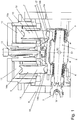
- the diagonal rolling mill shown according to the invention comprises three roller shafts 1 of identical construction, of which only one can be seen in the illustration.
- the roller shaft 1 has a roller body 2 which acts on a workpiece radially to a roller axis W or in the direction of a rolling force.
- the roller shaft 1 is rotated about the roller axis W via a cardanically articulated drive shaft 3.
- a rotary bearing 4, 5 supporting the rolling forces is arranged in front of and behind the roller body 2.
- the rotary bearings 4, 5 are in turn received and supported on a roller mill 6, the roller mill 6 being held movably relative to a frame 8 of the cross-rolling mill by means of a bearing 7.
- the roller mill can be pivotably adjusted both about a first adjusting axis S1 and about a second adjusting axis S2.
- the second positioning axis S2 follows in the illustration Fig. 1 perpendicular to the plane of the drawing.
- the positioning axes S1, S2 and the roller axis are perpendicular to each other, but do not have to intersect.
- the roller mill 6 is formed as a rigid component which is essentially yoke-shaped in cross section.
- Two support areas 6a of the roller mill hold the rotary bearings 4, 5 on the one hand and are supported on an intermediate member 9, 10 on the other hand.
- the intermediate members are arranged between the roller mill 6 or the rotary bearings 4, 5 on the one hand and in each case one of two actuators 11, 12 on the other hand.
- the roller 1 is adjusted by aligning the roller mill 6 and thus the rotary bearings 4, 5.
- the actuators 11, 12, which are designed as hydraulic cylinders, are each positioned.
- the actuators 11, 12 can also transmit the rolling force exerted on the workpiece.
- the roller mill 6 is also pulled against the rolling force by a tension member 13 designed as a hydraulic cylinder, so that the roller mill 6 is pressed firmly against the actuators at all times.
- the force of the tension member is smaller than the force of the actuators and ensures play-free positioning of the roller shaft 1 or enables the workpiece to be released.
- the intermediate elements 9, 10 are each of the same design and are used to compensate for tilting and offset movements occurring during the adjustment between the actuators 11, 12 on the one hand and the roller mill 6 or the roller shaft 1 on the other.
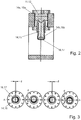
- the intermediate members 9, 10 each comprise a pressure stalk 14, 15.
- the pressure sticks 14, 15 can each be pivoted in several directions. This is achieved by spherical bearings of the pressure stilts 14, 15.
- the pressure stilts are each provided on the actuator side with a concave dome surface 14a, 15a, a corresponding convex dome surface being provided on the actuator.
- the pressure stilts are also provided with a concave spherical surface 14b, 15b.
- An essentially hemispherical spherical cap 16, 17 is inserted into the end of the plunger 14, 15. This can be pivoted with respect to the pressure stilts via the spherical surface 14b, 15b and bears against the roller mill 6 with a flat counter surface. In this way, a lateral offset of the counter surface with respect to the roller mill can also be made possible if necessary.
- domes which are curved in reverse can also be provided, for example convex domes on the pressure stilts 14, 15 and correspondingly concave domes on the actuators 14, 15 and / or the bearing domes 16, 17.
- FIG. 3 clarifies, in which a plunger 14, 15 is shown, which is pivoted in four different exemplary spatial directions by an angle up to a stop.
- a maximum lateral offset d of the counter surfaces of the bearing caps 16, 17 is made possible by the pivoting.
Landscapes
- Engineering & Computer Science (AREA)
- Mechanical Engineering (AREA)
- Rolls And Other Rotary Bodies (AREA)
- Reduction Rolling/Reduction Stand/Operation Of Reduction Machine (AREA)
- Support Of The Bearing (AREA)
- Crushing And Grinding (AREA)
- Friction Gearing (AREA)
Description
Die Erfindung betrifft ein Schrägwalzwerk nach dem Oberbegriff des Anspruchs 1.The invention relates to a cross rolling mill according to the preamble of claim 1.
Bei weiteren bekannten Schrägwalzanordnungen, zum Beispiel nach dem Asselverfahren, kann die Anstellung einer Walzenwelle auch um zwei verschiedene Achsen erfolgen. Zur Entkoppelung der bei der Verstellung auftretenden Querkräfte zwischen den Kontaktflächen sind dabei Zwischenelemente erforderlich, die die Bauhöhe der Anstellung vergrößern.In other known cross roll arrangements, for example according to the Assel method, the roll shaft can also be adjusted around two different axes. In order to decouple the transverse forces occurring during the adjustment between the contact surfaces, intermediate elements are required which increase the overall height of the employment.
Es ist die Aufgabe der Erfindung, ein Schrägwalzwerk anzugeben, bei dem eine reibungsarme Verstellung der Walzenwellen ermöglicht ist.It is the object of the invention to provide a cross-rolling mill in which a low-friction adjustment of the roller shafts is made possible.
Diese Aufgabe wird für ein eingangs genanntes Schrägwalzwerk erfindungsgemäß mit den kennzeichnenden Merkmalen des Anspruchs 1 gelöst. Durch die Verschwenkbarkeit der Druckstelze ist ein einfacher und reibungsarmer Positionsausgleich zwischen der Walzenwelle und dem Stellglied ermöglicht, der insbesondere in mehrere Richtungen erfolgen kann.This object is achieved according to the invention for a cross-rolling mill mentioned at the outset with the characterizing features of claim 1. Due to the pivotability of the plunger, a simple and low-friction position compensation between the roller shaft and the actuator is made possible, which can take place in particular in several directions.
Die Anzahl der Walzenwellen kann bevorzugt zwei, drei oder auch vier betragen. Insbesondere kann das Schrägwalzwerk nach dem Asselverfahren oder zumindest dem Asselverfahren ähnlich arbeiten.The number of roller shafts can preferably be two, three or even four. In particular, the cross rolling mill can work similarly according to the Assel method or at least the Assel method.
Eine Ausrichtung der Walzenachse um die Stellachsen ist im Sinne der Erfindung geometrisch gemeint, so dass die Stellachsen keine körperlichen Wellen oder Ähnliches umfassen müssen. Die Stellachsen können bevorzugt jeweils senkrecht zu der Walzenachse ausgerichtet sein, insbesondere auch senkrecht zueinander.Alignment of the roller axis around the positioning axes is meant geometrically in the sense of the invention, so that the positioning axes do not have any physical waves or Must include something similar. The adjusting axes can preferably each be oriented perpendicular to the roller axis, in particular also perpendicular to one another.
Ein Stellglied kann im Sinne der Erfindung jeder Aktuator sein, mittels dessen die Walzenachse verstellte wird. Insbesondere können hydraulische Zylinder oder auch elektromechanische Stellglieder vorgesehen sein. Das Stellglied kann allgemein bevorzugt dazu ausgelegt sein, die Walzkraft auf das Werkstück auszuüben.Within the meaning of the invention, an actuator can be any actuator by means of which the roller axis is adjusted. In particular, hydraulic cylinders or electromechanical actuators can be provided. The actuator can generally preferably be designed to exert the rolling force on the workpiece.
Bei einer bevorzugten Ausführungsform der Erfindung ist es vorgesehen, dass die Walzenwelle an zwei gegenüberliegenden Enden jeweils zumindest ein Drehlager und eine verschwenkbare Druckstelze aufweist. Hierdurch kann eine vollständige und besonders reibungsarm verstellbare Abstützung über die verschwenkbaren Druckstelzen erfolgen.In a preferred embodiment of the invention, it is provided that the roller shaft has at least one rotary bearing and a pivotable pressure stilts at two opposite ends. In this way, a complete and particularly low-friction adjustable support can take place via the pivotable pressure stilts.
Allgemein vorteilhaft ist es im Interesse einer einfachen und effektiven Konstruktion vorgesehen, dass die Walzenwelle an einem Walzenstuhl aufgenommen ist, wobei der Walzenstuhl um die Stellachsen bewegbar gelagert ist und die Druckstelzen gegenüber dem Walzenstuhl abgestützt sind. Der Walzenstuhl kann dabei als in sich starrer, aber gegenüber einem Gerüst bewegbarer Rahmen ausgebildet sein.In the interest of a simple and effective construction, it is generally advantageous that the roller shaft is received on a roller mill, the roller mill being mounted so as to be movable about the positioning axes and the pressure stilts being supported relative to the roller mill. The roller mill can be designed as a frame which is rigid in itself but can be moved relative to a frame.
Bei einer vorteilhaften Detailgestaltung ist der Walzenstuhl dabei mittels eines bevorzugt hydraulischen Zugglieds entgegen der Richtung der Walzkraft kraftbeaufschlagt. Gemeinsam mit den Kräften der Stellglieder wird so insgesamt eine spielfreie Halterung der Walze in ihrer jeweiligen Anstellung erzielt.In an advantageous detailed design, the roller mill is subjected to force by means of a preferably hydraulic tension member against the direction of the rolling force. Together with the forces of the actuators, a play-free holding of the roller in its respective position is thus achieved overall.
Bei einer bevorzugten Ausführungsform der Erfindung hat die Druckstelze an zumindest einem Ende eine gegenüber der Druckstelze schwenkbare Lagerkalotte. Dies erlaubt einen einfachen seitlichen Versatz eines Auflagepunktes der Druckstelze bzw. der Lagerkalotte. Zudem kann die Lagerkalotte auf einfache Weise als Verschleißteil ausgetauscht werden.In a preferred embodiment of the invention, the pressure stilts have at least one end with a bearing cap which can be pivoted relative to the pressure stilts. This allows a simple lateral offset of one Point of contact of the pressure stilts or the bearing cap. In addition, the bearing cap can be easily replaced as a wearing part.
Im Interesse einer variablen Anstellung ist es bevorzugt vorgesehen, dass die Druckstelze ausgehend von einer Neutralposition in jede Raumrichtung um einen Winkel um einen Drehpunkt verschwenkbar ist.In the interest of a variable employment, it is preferably provided that the pressure stilts can be pivoted from an neutral position in every spatial direction by an angle about a pivot point.
Allgemein vorteilhaft sind zumindest zwei Walzenwellen, bevorzugt zumindest drei Walzenwellen, besonders bevorzugt sämtliche der Walzenwellen des Schrägwalzwerks gemäß einem der vorhergehend beschriebenen Merkmale verstellbar gelagert.Generally advantageous are at least two roller shafts, preferably at least three roller shafts, particularly preferably all of the roller shafts of the cross-rolling mill are adjustable in accordance with one of the features described above.
Allgemein ergibt sich aus einer erfindungsgemäßen Lagerung der Walzenwelle oder der Walzenwellen, dass eine Kompensation radialer Bewegungen zur Stellachse vorliegt. Ebenso ist eine Kompensation von Winkeligkeitsabweichungen senkrecht zur Verstellachse ermöglicht. Zudem können Bauhöhe und damit Rahmengröße und Gewicht des Schrägwalzwerks durch die Erfindung reduziert werden.In general, from a bearing arrangement of the roller shaft or roller shafts according to the invention, there is a compensation for radial movements to the actuating axis. Compensation for angularity deviations perpendicular to the adjustment axis is also possible. In addition, the height and thus the frame size and weight of the cross rolling mill can be reduced by the invention.
Durch die Erfindung werden Reibkräfte und Querkräfte der Anstellungskomponenten vermieden bzw. reduziert. Es ergibt sich zudem der Vorteil einer verbesserten Positioniergenauigkeit unter Last. Ferner ist das Schwingverhalten des Anstellungssystems verbessert und die Steifigkeit insgesamt erhöht.The invention avoids or reduces frictional forces and transverse forces of the adjustment components. There is also the advantage of improved positioning accuracy under load. Furthermore, the vibration behavior of the adjustment system is improved and the overall rigidity is increased.
Weitere Vorteile und Merkmale ergeben sich aus dem nachfolgend beschriebenen Ausführungsbeispiel sowie aus den abhängigen Ansprüchen.Further advantages and features result from the exemplary embodiment described below and from the dependent claims.
Nachfolgend wird ein bevorzugtes Ausführungsbeispiel der Erfindung beschrieben und anhand der anliegenden Zeichnungen näher erläutert.
- Fig. 1
- zeigt eine teilweise Schnittansicht eines erfindungsgemäßen Schrägwalzwerks.
- Fig. 2
- zeigt eine schematische Schnittansicht einer verschwenkbaren Druckstelze entlang der Schnittlinie A-A aus
Fig. 3 . - Fig. 3
- zeigt eine Draufsicht auf die Druckstelze in aus
Fig. 2 in vier extremalen Schwenkpositionen.
- Fig. 1
- shows a partial sectional view of a cross rolling mill according to the invention.
- Fig. 2
- shows a schematic sectional view of a pivotable pressure stilts along the section line AA from
Fig. 3 , - Fig. 3
- shows a top view of the pressure wilt in FIG
Fig. 2 in four extreme swivel positions.
Das in
Vor und hinter dem Walzenkörper 2 ist jeweils ein die Walzkräfte abstützendes Drehlager 4, 5 angeordnet. Die Drehlager 4, 5 sind ihrerseits an einem Walzenstuhl 6 aufgenommen und abgestützt, wobei der Walzenstuhl 6 mittels einer Lagerung 7 bewegbar gegenüber einem Rahmen 8 des Schrägwalzwerks gehalten ist. Dabei ist der Walzenstuhl sowohl um eine erste Stellachse S1 als auch um eine zweite Stellachse S2 einstellbar verschwenkbar. Die zweite Stellachse S2 verläuft in der Darstellung nach
Der Walzenstuhl 6 ist als starres, im Querschnitt im Wesentlichen jochförmiges Bauteil ausgeformt. Zwei Stützbereiche 6a des Walzenstuhls halten einerseits die Drehlager 4, 5 und sind andererseits an jeweils einem Zwischenglied 9, 10 abgestützt. Die Zwischenglieder sind zwischen dem Walzenstuhl 6 bzw. den Drehlagern 4, 5 einerseits und jeweils einem von zwei Stellgliedern 11, 12 andererseits angeordnet.The
Über die Ausrichtung des Walzenstuhls 6 und somit der Drehlager 4, 5 erfolgt die Anstellung der Walze 1. Hierzu werden die Stellglieder 11, 12, die vorliegend als hydraulische Zylinder ausgebildet sind, jeweils positioniert. Die Stellglieder 11, 12 können zudem die auf das Werkstück ausgeübte Walzkraft übertragen.The roller 1 is adjusted by aligning the
Der Walzenstuhl 6 wird zudem durch ein als hydraulischer Zylinder ausgebildetes Zugglied 13 entgegen der Walzkraft gezogen, so dass der Walzenstuhl 6 jederzeit fest gegen die Stellglieder gedrückt wird. Die Kraft des Zugglieds ist kleiner als die Kraft der Stellglieder und stellt eine spielfreie Positionierung der Walzenwelle 1 sicher bzw. ermöglicht eine Freigabe des Werkstücks.The
Die Zwischenglieder 9, 10 sind jeweils in gleicher Bauart ausgeführt und dienen der Kompensation von bei der Verstellung auftretenden Kipp- und Versatzbewegungen zwischen den Stellgliedern 11, 12 einerseits und dem Walzenstuhl 6 bzw. der Walzenwelle 1 andererseits. Vorliegend umfassen die Zwischenglieder 9, 10 jeweils eine Druckstelze 14, 15. Die Druckstelzen 14, 15 sind jeweils in mehrere Richtungen verschwenkbar. Dies wird durch kalottenförmige Lagerungen der Druckstelzen 14, 15 erzielt.The
Vorliegend sind die Druckstelzen jeweils stellgliedseitig mit einer konkaven Kalottenfläche 14a, 15a versehen, wobei an dem Stellglied eine entsprechende konvexe Kalottenfläche vorgesehen ist. Auf der Seite der Walzenwelle sind die Druckstelzen ebenfalls mit einer konkaven Kalottenfläche 14b, 15b versehen.In the present case, the pressure stilts are each provided on the actuator side with a
Dabei ist eine im Wesentlichen halbkugelförmige Lagerkalotte 16, 17 in das Ende der Druckstelze 14, 15 eingesetzt. Diese ist über die kalottenförmige Fläche 14b, 15b gegenüber der Druckstelze verschwenkbar und liegt mit einer planen Gegenfläche an dem Walzenstuhl 6 an. Hierdurch kann bei Bedarf auch ein seitlicher Versatz der Gegenfläche gegenüber dem Walzenstuhl ermöglicht werden.An essentially hemispherical
Es versteht sich, dass bei anderen Ausführungsformen auch umgekehrt gewölbte Kalottenflächen vorgesehen sein können, also zum Beispiel konvexe Kalottenflächen an den Druckstelzen 14, 15 und entsprechend konkave Kalottenflächen an den Stellgliedern 14, 15 und/oder den Lagerkalotten 16, 17.It goes without saying that in other embodiments, domes which are curved in reverse can also be provided, for example convex domes on the
Die Verstellung des Walzenstuhls um die in der Zeichnungsebene
Dies ist insbesondere in
- 11
- Walzenwelleroller shaft
- 22
- Walzenkörperroller body
- 33
- Antriebswelle, kardanisches GelenkDrive shaft, cardan joint
- 44
- erstes Drehlagerfirst pivot bearing
- 55
- zweites Drehlagersecond pivot bearing
- 66
- Walzenstuhlroll mill
- 6a6a
- Stützbereiche des WalzenstuhlsSupport areas of the roller mill
- 77
- Lagerung des WalzenstuhlsStorage of the roller mill
- 88th
- Rahmenframe
- 99
- erstes Zwischengliedfirst pontic
- 1010
- zweites Zwischengliedsecond pontic
- 1111
- erstes Stellgliedfirst actuator
- 1212
- zweites Stellgliedsecond actuator
- 1313
- Zuggliedtension member
- 1414
- erste Druckstelzefirst pressure stilts
- 14a14a
- konkave Kalottenflächeconcave dome surface
- 14b14b
- konkave Kalottenflächeconcave dome surface
- 1515
- zweite Druckstelzesecond pressure stilts
- 15a15a
- konkave Kalottenflächeconcave dome surface
- 15b15b
- konkave Kalottenflächeconcave dome surface
- 1616
- erste Lagerkalottefirst bearing cap
- 1717
- zweite Lagerkalottesecond bearing cap
- WW
- Walzenachseroll axis
- S1S1
- erste Stellachsefirst positioning axis
- S2S2
- zweite Stellachsesecond positioning axis
- dd
- seitlicher Versatzlateral offset
Claims (7)
- Cross-rolling mill, comprising
a plurality of roll shafts (1) which each exert a substantially radially directed rolling force on a workpiece,
wherein the orientation of a roll axis (W) of at least one of the roll shafts (1) is variably settable about a first setting axis (S1) and about a second setting axis (S2),
wherein an intermediate element (9, 10) is arranged between a rotary bearing (4, 5) of the roll shaft (1) and a setting element (11, 12),
characterised in that
the intermediate element (9, 10) comprises a pressure leg (14, 15) which transmits the rolling force and which is pivotable in a plurality of directions by means of a spherical bearing surface (14a, 14b, 15a, 15b). - Cross-rolling mill according to claim 1, characterised in that the roll shaft (1) has at two opposite ends in each instance at least one rotary bearing (4, 5) and a pivotable pressure leg (14, 15).
- Cross-rolling mill according to one of the preceding claims, characterised in that the roll shaft (1) is mounted on a roll chair (6), wherein the roll chair (6) is mounted to be movable about the setting axes (S1, S2) and the pressure legs (14, 15) are supported relative to the roll chair (6).
- Cross-rolling mill according to claim 3, characterised in that the roll chair (6) is loaded with force by means of, in particular, a hydraulic tension element (13) against the direction of the rolling force.
- Cross-rolling mill according to any one of the preceding claims, characterised in that the pressure leg (14, 15) has at at least one end a spherical bearing (16) pivotable relative to the pressure leg.
- Cross-rolling mill according to any one of the preceding claims, characterised in that the pressure leg (14, 15) starting from a neutral position is pivotable about a fulcrum in any spatial direction through an angle.
- Cross-rolling mill according to any one of the preceding claims, characterised in that at least two roll shafts (1), particularly at least three roll shafts, particularly all of the roll shafts of the cross-rolling mill, are mounted to be adjustable in accordance with any one of the preceding claims.
Priority Applications (1)
| Application Number | Priority Date | Filing Date | Title |
|---|---|---|---|
| PL17781472T PL3525945T3 (en) | 2016-10-11 | 2017-10-10 | Cross-rolling mill |
Applications Claiming Priority (2)
| Application Number | Priority Date | Filing Date | Title |
|---|---|---|---|
| DE102016219723.1A DE102016219723A1 (en) | 2016-10-11 | 2016-10-11 | Piercing mill |
| PCT/EP2017/075784 WO2018069303A1 (en) | 2016-10-11 | 2017-10-10 | Cross-rolling mill |
Publications (2)
| Publication Number | Publication Date |
|---|---|
| EP3525945A1 EP3525945A1 (en) | 2019-08-21 |
| EP3525945B1 true EP3525945B1 (en) | 2020-02-19 |
Family
ID=60051513
Family Applications (1)
| Application Number | Title | Priority Date | Filing Date |
|---|---|---|---|
| EP17781472.0A Active EP3525945B1 (en) | 2016-10-11 | 2017-10-10 | Cross-rolling mill |
Country Status (9)
| Country | Link |
|---|---|
| US (1) | US11400498B2 (en) |
| EP (1) | EP3525945B1 (en) |
| JP (1) | JP6803992B2 (en) |
| CN (1) | CN109843457B (en) |
| DE (1) | DE102016219723A1 (en) |
| ES (1) | ES2784391T3 (en) |
| PL (1) | PL3525945T3 (en) |
| RU (1) | RU2717425C1 (en) |
| WO (1) | WO2018069303A1 (en) |
Families Citing this family (3)
| Publication number | Priority date | Publication date | Assignee | Title |
|---|---|---|---|---|
| DE102019123836A1 (en) * | 2019-09-05 | 2021-03-11 | Sms Group Gmbh | Cross rolling unit and method for adjusting the rolling pass of a cross rolling unit |
| CN112986854B (en) * | 2021-02-03 | 2022-10-04 | 宇能电气有限公司 | Portable aviation starting power supply detection equipment |
| CN113843379B (en) * | 2021-10-26 | 2022-04-22 | 宁波大学 | Three-roller skew rolling device for forming stepped shaft |
Family Cites Families (16)
| Publication number | Priority date | Publication date | Assignee | Title |
|---|---|---|---|---|
| US2017374A (en) * | 1932-09-07 | 1935-10-15 | Nat Tube Co | Tube rolling mill |
| GB1289098A (en) * | 1968-10-21 | 1972-09-13 | ||
| DE2814493C3 (en) * | 1978-03-31 | 1980-12-18 | Mannesmann Ag, 4000 Duesseldorf | Cross rolling mill |
| US4348952A (en) * | 1981-01-19 | 1982-09-14 | Usm Corporation | Cross axis mechanism |
| DE3406841A1 (en) | 1984-02-23 | 1985-09-12 | Mannesmann AG, 4000 Düsseldorf | ROLLER ADJUSTMENT FOR A THREE-ROLLER BEVEL BEARING MILL |
| SU1251987A1 (en) * | 1985-04-15 | 1986-08-23 | Предприятие П/Я В-2869 | Versions of multihigh working st-and |
| RU2074777C1 (en) * | 1994-10-12 | 1997-03-10 | Акционерное общество "Череповецкий сталепрокатный завод" | Multiroll stand |
| JP3334771B2 (en) * | 1995-01-23 | 2002-10-15 | 石川島播磨重工業株式会社 | Rolling mill |
| DE19510694A1 (en) * | 1995-03-14 | 1996-09-19 | Mannesmann Ag | Roll stand with crossed work rolls |
| US5655398A (en) * | 1995-05-11 | 1997-08-12 | Danieli United, A Division Of Danieli Corporation | Roll crossing and shifting system |
| US5924319A (en) * | 1998-07-07 | 1999-07-20 | Danieli United | Roll crossing, offsetting, bending and shifting system for rolling mills |
| DE10030823C2 (en) * | 2000-06-23 | 2003-08-07 | Gmt Ges Fuer Metallurg Technol | 3-roll cross-rolling mill |
| DE10349056A1 (en) * | 2003-10-17 | 2005-05-19 | Kocks Technik Gmbh & Co. Kg | Process for rolling rolling stock e.g. metal rods in a rolling mill comprises measuring the rotation of the rolling stock about its longitudinal direction, and controlling a drive parameter of a planetary cross rolling mill |
| CN2784100Y (en) * | 2005-04-19 | 2006-05-31 | 江苏包罗铜材集团股份有限公司 | Three-roller cold perforating machine and hole enlarging machine for skew rolling |
| CN101758073B (en) * | 2009-12-22 | 2012-06-27 | 太原重工股份有限公司 | Diagonal rolling double-roller puncher having cast-weld structure |
| EP3108978B1 (en) * | 2015-06-26 | 2019-02-20 | DANIELI & C. OFFICINE MECCANICHE S.p.A. | Rolling stand and rolling method |
-
2016
- 2016-10-11 DE DE102016219723.1A patent/DE102016219723A1/en not_active Withdrawn
-
2017
- 2017-10-10 CN CN201780062830.9A patent/CN109843457B/en active Active
- 2017-10-10 PL PL17781472T patent/PL3525945T3/en unknown
- 2017-10-10 WO PCT/EP2017/075784 patent/WO2018069303A1/en active Search and Examination
- 2017-10-10 RU RU2019110213A patent/RU2717425C1/en active
- 2017-10-10 ES ES17781472T patent/ES2784391T3/en active Active
- 2017-10-10 EP EP17781472.0A patent/EP3525945B1/en active Active
- 2017-10-10 US US16/341,130 patent/US11400498B2/en active Active
- 2017-10-10 JP JP2019540699A patent/JP6803992B2/en active Active
Non-Patent Citations (1)
| Title |
|---|
| None * |
Also Published As
| Publication number | Publication date |
|---|---|
| PL3525945T3 (en) | 2020-07-13 |
| CN109843457A (en) | 2019-06-04 |
| US11400498B2 (en) | 2022-08-02 |
| ES2784391T3 (en) | 2020-09-25 |
| JP2019530582A (en) | 2019-10-24 |
| DE102016219723A1 (en) | 2018-04-12 |
| US20200188973A1 (en) | 2020-06-18 |
| WO2018069303A1 (en) | 2018-04-19 |
| JP6803992B2 (en) | 2020-12-23 |
| RU2717425C1 (en) | 2020-03-23 |
| CN109843457B (en) | 2020-10-23 |
| EP3525945A1 (en) | 2019-08-21 |
Similar Documents
| Publication | Publication Date | Title |
|---|---|---|
| EP2049016B1 (en) | Device having a directly driven rotating body and an aerostatic bearing | |
| EP0019136B1 (en) | Rotary drum with a live ring for supporting the rotary drum on an adjustable roller support | |
| EP3350463B1 (en) | Rotary bearing | |
| DE4126545C2 (en) | Three-ring roller bearings for the journals of the cylinders of printing machines | |
| EP3525945B1 (en) | Cross-rolling mill | |
| EP1929164B1 (en) | Expander roller | |
| DE2406697B2 (en) | ARTICULATED CONNECTION BETWEEN A CROSS HEAD AND A POLE | |
| EP1668263B1 (en) | Pivot bearing arrangement of a rotational body | |
| WO2015144460A1 (en) | Plain bearing system | |
| DE69819562T2 (en) | SUPPORT ROLLER ASSEMBLY WITH DYNAMIC BALANCE CONTROL | |
| EP0447651A1 (en) | Deflection-controlled roll | |
| DE2402101C3 (en) | Device for connecting the form cylinder of a rotary printing press to its drive shaft | |
| AT392661B (en) | PRESS ROLLER WHICH THE BEND IS ADJUSTABLE | |
| EP3308862B1 (en) | Bearing element adapted for supporting a grinding table in a roller mill | |
| DE102015221762A1 (en) | Device for adjusting a compression roller of a compression frame | |
| DE3208780A1 (en) | PTO SHAFT WITH DIRECTIONAL DEVICE | |
| EP3581291A1 (en) | Sheet metal bending machine with variable roller geometry | |
| EP1989454B1 (en) | Roller | |
| EP3161197B1 (en) | Pressing device for pressing a braided tube onto a component core and braiding machine | |
| DE102004022007B4 (en) | Bearing for a roll of a rotary printing press, in particular for an applicator roll of a coating unit | |
| EP3116667B1 (en) | Shaft-hub connection and drive arrangement having such a shaft-hub connection | |
| EP3772598B1 (en) | Metal cage for holding rolling bodies in a rolling bearing | |
| DE3113080C2 (en) | "Rotor head for single-blade rotor of wind energy plants" | |
| DE102011104704B4 (en) | Device for adjusting the axial position of an axial bearing of an axle relative to a reference component and rolling stand with such a device | |
| DE2802742C2 (en) | Pulling device for a mandrel rolling mill |
Legal Events
| Date | Code | Title | Description |
|---|---|---|---|
| STAA | Information on the status of an ep patent application or granted ep patent |
Free format text: STATUS: UNKNOWN |
|
| STAA | Information on the status of an ep patent application or granted ep patent |
Free format text: STATUS: THE INTERNATIONAL PUBLICATION HAS BEEN MADE |
|
| PUAI | Public reference made under article 153(3) epc to a published international application that has entered the european phase |
Free format text: ORIGINAL CODE: 0009012 |
|
| STAA | Information on the status of an ep patent application or granted ep patent |
Free format text: STATUS: REQUEST FOR EXAMINATION WAS MADE |
|
| 17P | Request for examination filed |
Effective date: 20190513 |
|
| AK | Designated contracting states |
Kind code of ref document: A1 Designated state(s): AL AT BE BG CH CY CZ DE DK EE ES FI FR GB GR HR HU IE IS IT LI LT LU LV MC MK MT NL NO PL PT RO RS SE SI SK SM TR |
|
| AX | Request for extension of the european patent |
Extension state: BA ME |
|
| GRAP | Despatch of communication of intention to grant a patent |
Free format text: ORIGINAL CODE: EPIDOSNIGR1 |
|
| STAA | Information on the status of an ep patent application or granted ep patent |
Free format text: STATUS: GRANT OF PATENT IS INTENDED |
|
| DAV | Request for validation of the european patent (deleted) | ||
| DAX | Request for extension of the european patent (deleted) | ||
| INTG | Intention to grant announced |
Effective date: 20190913 |
|
| GRAS | Grant fee paid |
Free format text: ORIGINAL CODE: EPIDOSNIGR3 |
|
| GRAA | (expected) grant |
Free format text: ORIGINAL CODE: 0009210 |
|
| STAA | Information on the status of an ep patent application or granted ep patent |
Free format text: STATUS: THE PATENT HAS BEEN GRANTED |
|
| AK | Designated contracting states |
Kind code of ref document: B1 Designated state(s): AL AT BE BG CH CY CZ DE DK EE ES FI FR GB GR HR HU IE IS IT LI LT LU LV MC MK MT NL NO PL PT RO RS SE SI SK SM TR |
|
| REG | Reference to a national code |
Ref country code: CH Ref legal event code: EP |
|
| REG | Reference to a national code |
Ref country code: DE Ref legal event code: R096 Ref document number: 502017003915 Country of ref document: DE |
|
| REG | Reference to a national code |
Ref country code: AT Ref legal event code: REF Ref document number: 1234346 Country of ref document: AT Kind code of ref document: T Effective date: 20200315 |
|
| REG | Reference to a national code |
Ref country code: IE Ref legal event code: FG4D Free format text: LANGUAGE OF EP DOCUMENT: GERMAN |
|
| REG | Reference to a national code |
Ref country code: NL Ref legal event code: MP Effective date: 20200219 |
|
| PG25 | Lapsed in a contracting state [announced via postgrant information from national office to epo] |
Ref country code: NO Free format text: LAPSE BECAUSE OF FAILURE TO SUBMIT A TRANSLATION OF THE DESCRIPTION OR TO PAY THE FEE WITHIN THE PRESCRIBED TIME-LIMIT Effective date: 20200519 Ref country code: FI Free format text: LAPSE BECAUSE OF FAILURE TO SUBMIT A TRANSLATION OF THE DESCRIPTION OR TO PAY THE FEE WITHIN THE PRESCRIBED TIME-LIMIT Effective date: 20200219 Ref country code: RS Free format text: LAPSE BECAUSE OF FAILURE TO SUBMIT A TRANSLATION OF THE DESCRIPTION OR TO PAY THE FEE WITHIN THE PRESCRIBED TIME-LIMIT Effective date: 20200219 |
|
| REG | Reference to a national code |
Ref country code: LT Ref legal event code: MG4D |
|
| PG25 | Lapsed in a contracting state [announced via postgrant information from national office to epo] |
Ref country code: HR Free format text: LAPSE BECAUSE OF FAILURE TO SUBMIT A TRANSLATION OF THE DESCRIPTION OR TO PAY THE FEE WITHIN THE PRESCRIBED TIME-LIMIT Effective date: 20200219 Ref country code: BG Free format text: LAPSE BECAUSE OF FAILURE TO SUBMIT A TRANSLATION OF THE DESCRIPTION OR TO PAY THE FEE WITHIN THE PRESCRIBED TIME-LIMIT Effective date: 20200519 Ref country code: SE Free format text: LAPSE BECAUSE OF FAILURE TO SUBMIT A TRANSLATION OF THE DESCRIPTION OR TO PAY THE FEE WITHIN THE PRESCRIBED TIME-LIMIT Effective date: 20200219 Ref country code: LV Free format text: LAPSE BECAUSE OF FAILURE TO SUBMIT A TRANSLATION OF THE DESCRIPTION OR TO PAY THE FEE WITHIN THE PRESCRIBED TIME-LIMIT Effective date: 20200219 Ref country code: IS Free format text: LAPSE BECAUSE OF FAILURE TO SUBMIT A TRANSLATION OF THE DESCRIPTION OR TO PAY THE FEE WITHIN THE PRESCRIBED TIME-LIMIT Effective date: 20200619 Ref country code: GR Free format text: LAPSE BECAUSE OF FAILURE TO SUBMIT A TRANSLATION OF THE DESCRIPTION OR TO PAY THE FEE WITHIN THE PRESCRIBED TIME-LIMIT Effective date: 20200520 |
|
| REG | Reference to a national code |
Ref country code: ES Ref legal event code: FG2A Ref document number: 2784391 Country of ref document: ES Kind code of ref document: T3 Effective date: 20200925 |
|
| PG25 | Lapsed in a contracting state [announced via postgrant information from national office to epo] |
Ref country code: NL Free format text: LAPSE BECAUSE OF FAILURE TO SUBMIT A TRANSLATION OF THE DESCRIPTION OR TO PAY THE FEE WITHIN THE PRESCRIBED TIME-LIMIT Effective date: 20200219 |
|
| PG25 | Lapsed in a contracting state [announced via postgrant information from national office to epo] |
Ref country code: CZ Free format text: LAPSE BECAUSE OF FAILURE TO SUBMIT A TRANSLATION OF THE DESCRIPTION OR TO PAY THE FEE WITHIN THE PRESCRIBED TIME-LIMIT Effective date: 20200219 Ref country code: RO Free format text: LAPSE BECAUSE OF FAILURE TO SUBMIT A TRANSLATION OF THE DESCRIPTION OR TO PAY THE FEE WITHIN THE PRESCRIBED TIME-LIMIT Effective date: 20200219 Ref country code: SK Free format text: LAPSE BECAUSE OF FAILURE TO SUBMIT A TRANSLATION OF THE DESCRIPTION OR TO PAY THE FEE WITHIN THE PRESCRIBED TIME-LIMIT Effective date: 20200219 Ref country code: EE Free format text: LAPSE BECAUSE OF FAILURE TO SUBMIT A TRANSLATION OF THE DESCRIPTION OR TO PAY THE FEE WITHIN THE PRESCRIBED TIME-LIMIT Effective date: 20200219 Ref country code: LT Free format text: LAPSE BECAUSE OF FAILURE TO SUBMIT A TRANSLATION OF THE DESCRIPTION OR TO PAY THE FEE WITHIN THE PRESCRIBED TIME-LIMIT Effective date: 20200219 Ref country code: PT Free format text: LAPSE BECAUSE OF FAILURE TO SUBMIT A TRANSLATION OF THE DESCRIPTION OR TO PAY THE FEE WITHIN THE PRESCRIBED TIME-LIMIT Effective date: 20200712 Ref country code: DK Free format text: LAPSE BECAUSE OF FAILURE TO SUBMIT A TRANSLATION OF THE DESCRIPTION OR TO PAY THE FEE WITHIN THE PRESCRIBED TIME-LIMIT Effective date: 20200219 Ref country code: SM Free format text: LAPSE BECAUSE OF FAILURE TO SUBMIT A TRANSLATION OF THE DESCRIPTION OR TO PAY THE FEE WITHIN THE PRESCRIBED TIME-LIMIT Effective date: 20200219 |
|
| REG | Reference to a national code |
Ref country code: DE Ref legal event code: R097 Ref document number: 502017003915 Country of ref document: DE |
|
| PLBE | No opposition filed within time limit |
Free format text: ORIGINAL CODE: 0009261 |
|
| STAA | Information on the status of an ep patent application or granted ep patent |
Free format text: STATUS: NO OPPOSITION FILED WITHIN TIME LIMIT |
|
| 26N | No opposition filed |
Effective date: 20201120 |
|
| REG | Reference to a national code |
Ref country code: CH Ref legal event code: PL |
|
| PG25 | Lapsed in a contracting state [announced via postgrant information from national office to epo] |
Ref country code: LU Free format text: LAPSE BECAUSE OF NON-PAYMENT OF DUE FEES Effective date: 20201010 Ref country code: MC Free format text: LAPSE BECAUSE OF FAILURE TO SUBMIT A TRANSLATION OF THE DESCRIPTION OR TO PAY THE FEE WITHIN THE PRESCRIBED TIME-LIMIT Effective date: 20200219 |
|
| REG | Reference to a national code |
Ref country code: BE Ref legal event code: MM Effective date: 20201031 |
|
| PG25 | Lapsed in a contracting state [announced via postgrant information from national office to epo] |
Ref country code: LI Free format text: LAPSE BECAUSE OF NON-PAYMENT OF DUE FEES Effective date: 20201031 Ref country code: CH Free format text: LAPSE BECAUSE OF NON-PAYMENT OF DUE FEES Effective date: 20201031 Ref country code: BE Free format text: LAPSE BECAUSE OF NON-PAYMENT OF DUE FEES Effective date: 20201031 |
|
| PG25 | Lapsed in a contracting state [announced via postgrant information from national office to epo] |
Ref country code: IE Free format text: LAPSE BECAUSE OF NON-PAYMENT OF DUE FEES Effective date: 20201010 |
|
| PG25 | Lapsed in a contracting state [announced via postgrant information from national office to epo] |
Ref country code: TR Free format text: LAPSE BECAUSE OF FAILURE TO SUBMIT A TRANSLATION OF THE DESCRIPTION OR TO PAY THE FEE WITHIN THE PRESCRIBED TIME-LIMIT Effective date: 20200219 Ref country code: MT Free format text: LAPSE BECAUSE OF FAILURE TO SUBMIT A TRANSLATION OF THE DESCRIPTION OR TO PAY THE FEE WITHIN THE PRESCRIBED TIME-LIMIT Effective date: 20200219 Ref country code: CY Free format text: LAPSE BECAUSE OF FAILURE TO SUBMIT A TRANSLATION OF THE DESCRIPTION OR TO PAY THE FEE WITHIN THE PRESCRIBED TIME-LIMIT Effective date: 20200219 |
|
| GBPC | Gb: european patent ceased through non-payment of renewal fee |
Effective date: 20211010 |
|
| PG25 | Lapsed in a contracting state [announced via postgrant information from national office to epo] |
Ref country code: MK Free format text: LAPSE BECAUSE OF FAILURE TO SUBMIT A TRANSLATION OF THE DESCRIPTION OR TO PAY THE FEE WITHIN THE PRESCRIBED TIME-LIMIT Effective date: 20200219 Ref country code: AL Free format text: LAPSE BECAUSE OF FAILURE TO SUBMIT A TRANSLATION OF THE DESCRIPTION OR TO PAY THE FEE WITHIN THE PRESCRIBED TIME-LIMIT Effective date: 20200219 |
|
| PG25 | Lapsed in a contracting state [announced via postgrant information from national office to epo] |
Ref country code: GB Free format text: LAPSE BECAUSE OF NON-PAYMENT OF DUE FEES Effective date: 20211010 |
|
| P01 | Opt-out of the competence of the unified patent court (upc) registered |
Effective date: 20230707 |
|
| PG25 | Lapsed in a contracting state [announced via postgrant information from national office to epo] |
Ref country code: SI Free format text: LAPSE BECAUSE OF FAILURE TO SUBMIT A TRANSLATION OF THE DESCRIPTION OR TO PAY THE FEE WITHIN THE PRESCRIBED TIME-LIMIT Effective date: 20200219 |
|
| PGFP | Annual fee paid to national office [announced via postgrant information from national office to epo] |
Ref country code: PL Payment date: 20230928 Year of fee payment: 7 |
|
| PGFP | Annual fee paid to national office [announced via postgrant information from national office to epo] |
Ref country code: ES Payment date: 20231227 Year of fee payment: 7 |
|
| PGFP | Annual fee paid to national office [announced via postgrant information from national office to epo] |
Ref country code: IT Payment date: 20231026 Year of fee payment: 7 Ref country code: FR Payment date: 20231026 Year of fee payment: 7 Ref country code: DE Payment date: 20231020 Year of fee payment: 7 Ref country code: AT Payment date: 20231020 Year of fee payment: 7 |