EP3525703B1 - Behandlungsvorrichtungen - Google Patents
Behandlungsvorrichtungen Download PDFInfo
- Publication number
- EP3525703B1 EP3525703B1 EP17862591.9A EP17862591A EP3525703B1 EP 3525703 B1 EP3525703 B1 EP 3525703B1 EP 17862591 A EP17862591 A EP 17862591A EP 3525703 B1 EP3525703 B1 EP 3525703B1
- Authority
- EP
- European Patent Office
- Prior art keywords
- fluid
- ports
- therapeutic
- ablation
- medical device
- Prior art date
- Legal status (The legal status is an assumption and is not a legal conclusion. Google has not performed a legal analysis and makes no representation as to the accuracy of the status listed.)
- Active
Links
- 238000011282 treatment Methods 0.000 title description 15
- 238000002679 ablation Methods 0.000 claims description 95
- 239000012530 fluid Substances 0.000 claims description 76
- 210000004027 cell Anatomy 0.000 claims description 67
- 230000001225 therapeutic effect Effects 0.000 claims description 53
- 238000000034 method Methods 0.000 claims description 22
- 239000003550 marker Substances 0.000 claims description 17
- 239000002458 cell surface marker Substances 0.000 claims description 13
- 102000018697 Membrane Proteins Human genes 0.000 claims description 11
- 108010052285 Membrane Proteins Proteins 0.000 claims description 11
- 238000004891 communication Methods 0.000 claims description 7
- 230000004044 response Effects 0.000 claims description 6
- 239000000523 sample Substances 0.000 claims description 6
- 230000007704 transition Effects 0.000 claims description 4
- 102000004190 Enzymes Human genes 0.000 claims description 3
- 108090000790 Enzymes Proteins 0.000 claims description 3
- 102000004169 proteins and genes Human genes 0.000 claims description 3
- 108090000623 proteins and genes Proteins 0.000 claims description 3
- 101710132082 Pyrimidine/purine nucleoside phosphorylase Proteins 0.000 claims 1
- 102000013537 Thymidine Phosphorylase Human genes 0.000 claims 1
- 230000000717 retained effect Effects 0.000 claims 1
- 210000001519 tissue Anatomy 0.000 description 85
- 206010028980 Neoplasm Diseases 0.000 description 46
- FAPWRFPIFSIZLT-UHFFFAOYSA-M Sodium chloride Chemical compound [Na+].[Cl-] FAPWRFPIFSIZLT-UHFFFAOYSA-M 0.000 description 24
- 239000011780 sodium chloride Substances 0.000 description 23
- 230000014509 gene expression Effects 0.000 description 20
- 201000011510 cancer Diseases 0.000 description 17
- 229940079593 drug Drugs 0.000 description 15
- 239000003814 drug Substances 0.000 description 15
- 238000007674 radiofrequency ablation Methods 0.000 description 11
- 230000006870 function Effects 0.000 description 10
- 238000002271 resection Methods 0.000 description 10
- 208000026310 Breast neoplasm Diseases 0.000 description 9
- 230000002262 irrigation Effects 0.000 description 9
- 238000003973 irrigation Methods 0.000 description 9
- 102000005962 receptors Human genes 0.000 description 9
- 108020003175 receptors Proteins 0.000 description 9
- 102000008096 B7-H1 Antigen Human genes 0.000 description 8
- 108010074708 B7-H1 Antigen Proteins 0.000 description 8
- 239000000463 material Substances 0.000 description 8
- 206010006187 Breast cancer Diseases 0.000 description 7
- 102100040678 Programmed cell death protein 1 Human genes 0.000 description 7
- 101710089372 Programmed cell death protein 1 Proteins 0.000 description 7
- 210000000481 breast Anatomy 0.000 description 7
- -1 CD 147 Proteins 0.000 description 6
- 230000004913 activation Effects 0.000 description 6
- 238000001356 surgical procedure Methods 0.000 description 6
- 102000001301 EGF receptor Human genes 0.000 description 5
- 108060006698 EGF receptor Proteins 0.000 description 5
- 238000009175 antibody therapy Methods 0.000 description 5
- 201000010099 disease Diseases 0.000 description 5
- 208000037265 diseases, disorders, signs and symptoms Diseases 0.000 description 5
- 208000002154 non-small cell lung carcinoma Diseases 0.000 description 5
- 208000029729 tumor suppressor gene on chromosome 11 Diseases 0.000 description 5
- 230000002159 abnormal effect Effects 0.000 description 4
- 230000008901 benefit Effects 0.000 description 4
- 230000002596 correlated effect Effects 0.000 description 4
- 230000000875 corresponding effect Effects 0.000 description 4
- 230000000694 effects Effects 0.000 description 4
- 238000005259 measurement Methods 0.000 description 4
- 230000007935 neutral effect Effects 0.000 description 4
- 230000003827 upregulation Effects 0.000 description 4
- 101710163595 Chaperone protein DnaK Proteins 0.000 description 3
- 101710178376 Heat shock 70 kDa protein Proteins 0.000 description 3
- 101710152018 Heat shock cognate 70 kDa protein Proteins 0.000 description 3
- 101001012157 Homo sapiens Receptor tyrosine-protein kinase erbB-2 Proteins 0.000 description 3
- 102100030086 Receptor tyrosine-protein kinase erbB-2 Human genes 0.000 description 3
- 230000009471 action Effects 0.000 description 3
- 210000001035 gastrointestinal tract Anatomy 0.000 description 3
- 230000005484 gravity Effects 0.000 description 3
- 210000004185 liver Anatomy 0.000 description 3
- 238000012544 monitoring process Methods 0.000 description 3
- 239000012811 non-conductive material Substances 0.000 description 3
- 230000002018 overexpression Effects 0.000 description 3
- 230000005855 radiation Effects 0.000 description 3
- 238000007493 shaping process Methods 0.000 description 3
- 239000010409 thin film Substances 0.000 description 3
- 101800001288 Atrial natriuretic factor Proteins 0.000 description 2
- 102400001282 Atrial natriuretic peptide Human genes 0.000 description 2
- 101800001890 Atrial natriuretic peptide Proteins 0.000 description 2
- 102000004219 Brain-derived neurotrophic factor Human genes 0.000 description 2
- 108090000715 Brain-derived neurotrophic factor Proteins 0.000 description 2
- 102000049320 CD36 Human genes 0.000 description 2
- 108010045374 CD36 Antigens Proteins 0.000 description 2
- 101150029707 ERBB2 gene Proteins 0.000 description 2
- 102000018233 Fibroblast Growth Factor Human genes 0.000 description 2
- 108050007372 Fibroblast Growth Factor Proteins 0.000 description 2
- 102000003688 G-Protein-Coupled Receptors Human genes 0.000 description 2
- 108090000045 G-Protein-Coupled Receptors Proteins 0.000 description 2
- 102100041003 Glutamate carboxypeptidase 2 Human genes 0.000 description 2
- 102000003886 Glycoproteins Human genes 0.000 description 2
- 108090000288 Glycoproteins Proteins 0.000 description 2
- 102100034051 Heat shock protein HSP 90-alpha Human genes 0.000 description 2
- 101000914324 Homo sapiens Carcinoembryonic antigen-related cell adhesion molecule 5 Proteins 0.000 description 2
- 101000892862 Homo sapiens Glutamate carboxypeptidase 2 Proteins 0.000 description 2
- 102000004895 Lipoproteins Human genes 0.000 description 2
- 108090001030 Lipoproteins Proteins 0.000 description 2
- 102000003735 Mesothelin Human genes 0.000 description 2
- 108090000015 Mesothelin Proteins 0.000 description 2
- 102100027347 Neural cell adhesion molecule 1 Human genes 0.000 description 2
- 108090000742 Neurotrophin 3 Proteins 0.000 description 2
- 102100029268 Neurotrophin-3 Human genes 0.000 description 2
- 102000003683 Neurotrophin-4 Human genes 0.000 description 2
- 108090000099 Neurotrophin-4 Proteins 0.000 description 2
- 102100021768 Phosphoserine aminotransferase Human genes 0.000 description 2
- 108010072866 Prostate-Specific Antigen Proteins 0.000 description 2
- 108010007100 Pulmonary Surfactant-Associated Protein A Proteins 0.000 description 2
- 102100027773 Pulmonary surfactant-associated protein A2 Human genes 0.000 description 2
- 108010065472 Vimentin Proteins 0.000 description 2
- 102000013127 Vimentin Human genes 0.000 description 2
- 210000004369 blood Anatomy 0.000 description 2
- 239000008280 blood Substances 0.000 description 2
- 229940077737 brain-derived neurotrophic factor Drugs 0.000 description 2
- NSQLIUXCMFBZME-MPVJKSABSA-N carperitide Chemical compound C([C@H]1C(=O)NCC(=O)NCC(=O)N[C@@H](CCCNC(N)=N)C(=O)N[C@@H](CCSC)C(=O)N[C@@H](CC(O)=O)C(=O)N[C@@H](CCCNC(N)=N)C(=O)N[C@H](C(NCC(=O)N[C@@H](C)C(=O)N[C@@H](CCC(N)=O)C(=O)N[C@@H](CO)C(=O)NCC(=O)N[C@@H](CC(C)C)C(=O)NCC(=O)N[C@@H](CSSC[C@@H](C(=O)N1)NC(=O)[C@H](CO)NC(=O)[C@H](CO)NC(=O)[C@H](CCCNC(N)=N)NC(=O)[C@H](CCCNC(N)=N)NC(=O)[C@H](CC(C)C)NC(=O)[C@@H](N)CO)C(=O)N[C@@H](CC(N)=O)C(=O)N[C@@H](CO)C(=O)N[C@@H](CC=1C=CC=CC=1)C(=O)N[C@@H](CCCNC(N)=N)C(=O)N[C@@H](CC=1C=CC(O)=CC=1)C(O)=O)=O)[C@@H](C)CC)C1=CC=CC=C1 NSQLIUXCMFBZME-MPVJKSABSA-N 0.000 description 2
- 239000004020 conductor Substances 0.000 description 2
- 238000010276 construction Methods 0.000 description 2
- 238000013461 design Methods 0.000 description 2
- 238000010586 diagram Methods 0.000 description 2
- 230000004069 differentiation Effects 0.000 description 2
- 229940126864 fibroblast growth factor Drugs 0.000 description 2
- 238000002847 impedance measurement Methods 0.000 description 2
- 238000002955 isolation Methods 0.000 description 2
- 150000002632 lipids Chemical class 0.000 description 2
- 230000036210 malignancy Effects 0.000 description 2
- 230000003211 malignant effect Effects 0.000 description 2
- 238000010197 meta-analysis Methods 0.000 description 2
- 229910052751 metal Inorganic materials 0.000 description 2
- 239000002184 metal Substances 0.000 description 2
- 229940032018 neurotrophin 3 Drugs 0.000 description 2
- 229940097998 neurotrophin 4 Drugs 0.000 description 2
- 210000000056 organ Anatomy 0.000 description 2
- 210000000496 pancreas Anatomy 0.000 description 2
- 230000010412 perfusion Effects 0.000 description 2
- 229920001481 poly(stearyl methacrylate) Polymers 0.000 description 2
- 229920001184 polypeptide Polymers 0.000 description 2
- 238000010837 poor prognosis Methods 0.000 description 2
- 102000004196 processed proteins & peptides Human genes 0.000 description 2
- 108090000765 processed proteins & peptides Proteins 0.000 description 2
- 238000004393 prognosis Methods 0.000 description 2
- 125000006850 spacer group Chemical group 0.000 description 2
- 239000000126 substance Substances 0.000 description 2
- 238000011477 surgical intervention Methods 0.000 description 2
- 102000035160 transmembrane proteins Human genes 0.000 description 2
- 108091005703 transmembrane proteins Proteins 0.000 description 2
- 210000005048 vimentin Anatomy 0.000 description 2
- 108091005477 5-HT3 receptors Proteins 0.000 description 1
- 102000035037 5-HT3 receptors Human genes 0.000 description 1
- 102000040125 5-hydroxytryptamine receptor family Human genes 0.000 description 1
- 108091032151 5-hydroxytryptamine receptor family Proteins 0.000 description 1
- 102100031585 ADP-ribosyl cyclase/cyclic ADP-ribose hydrolase 1 Human genes 0.000 description 1
- 102000003678 AMPA Receptors Human genes 0.000 description 1
- 108090000078 AMPA Receptors Proteins 0.000 description 1
- 102000009346 Adenosine receptors Human genes 0.000 description 1
- 108050000203 Adenosine receptors Proteins 0.000 description 1
- 108060003345 Adrenergic Receptor Proteins 0.000 description 1
- 102000017910 Adrenergic receptor Human genes 0.000 description 1
- 102100035248 Alpha-(1,3)-fucosyltransferase 4 Human genes 0.000 description 1
- 102100022749 Aminopeptidase N Human genes 0.000 description 1
- 102000008873 Angiotensin II receptor Human genes 0.000 description 1
- 108050000824 Angiotensin II receptor Proteins 0.000 description 1
- 208000031295 Animal disease Diseases 0.000 description 1
- 102100038080 B-cell receptor CD22 Human genes 0.000 description 1
- 102100022005 B-lymphocyte antigen CD20 Human genes 0.000 description 1
- 102100024217 CAMPATH-1 antigen Human genes 0.000 description 1
- 102100032912 CD44 antigen Human genes 0.000 description 1
- 108010065524 CD52 Antigen Proteins 0.000 description 1
- 102100025222 CD63 antigen Human genes 0.000 description 1
- 102100027221 CD81 antigen Human genes 0.000 description 1
- 102000016843 Calbindin 2 Human genes 0.000 description 1
- 108010028326 Calbindin 2 Proteins 0.000 description 1
- 101100507655 Canis lupus familiaris HSPA1 gene Proteins 0.000 description 1
- 102000018208 Cannabinoid Receptor Human genes 0.000 description 1
- 108050007331 Cannabinoid receptor Proteins 0.000 description 1
- 102000003727 Caveolin 1 Human genes 0.000 description 1
- 108090000026 Caveolin 1 Proteins 0.000 description 1
- 102000000844 Cell Surface Receptors Human genes 0.000 description 1
- 108010001857 Cell Surface Receptors Proteins 0.000 description 1
- 102100025064 Cellular tumor antigen p53 Human genes 0.000 description 1
- 102000004859 Cholecystokinin Receptors Human genes 0.000 description 1
- 108090001085 Cholecystokinin Receptors Proteins 0.000 description 1
- 102000007345 Chromogranins Human genes 0.000 description 1
- 108010007718 Chromogranins Proteins 0.000 description 1
- 108090000599 Claudin-3 Proteins 0.000 description 1
- 102100038423 Claudin-3 Human genes 0.000 description 1
- 108090000601 Claudin-4 Proteins 0.000 description 1
- 102100038447 Claudin-4 Human genes 0.000 description 1
- 208000001333 Colorectal Neoplasms Diseases 0.000 description 1
- 102100032768 Complement receptor type 2 Human genes 0.000 description 1
- 102100021202 Desmocollin-1 Human genes 0.000 description 1
- 101710157876 Desmocollin-1 Proteins 0.000 description 1
- 102000015554 Dopamine receptor Human genes 0.000 description 1
- 108050004812 Dopamine receptor Proteins 0.000 description 1
- 108010066687 Epithelial Cell Adhesion Molecule Proteins 0.000 description 1
- 102000018651 Epithelial Cell Adhesion Molecule Human genes 0.000 description 1
- 102100033176 Epithelial membrane protein 2 Human genes 0.000 description 1
- 108050009423 Epithelial membrane protein 2 Proteins 0.000 description 1
- 108010075944 Erythropoietin Receptors Proteins 0.000 description 1
- 102100036509 Erythropoietin receptor Human genes 0.000 description 1
- 108090000839 GABA-A Receptors Proteins 0.000 description 1
- 108060003377 GABA-B receptor Proteins 0.000 description 1
- 102000017934 GABA-B receptor Human genes 0.000 description 1
- 108010086407 GABA-C receptor Proteins 0.000 description 1
- 102100021260 Galactosylgalactosylxylosylprotein 3-beta-glucuronosyltransferase 1 Human genes 0.000 description 1
- 108010063919 Glucagon Receptors Proteins 0.000 description 1
- 102100040890 Glucagon receptor Human genes 0.000 description 1
- 102000018899 Glutamate Receptors Human genes 0.000 description 1
- 108010027915 Glutamate Receptors Proteins 0.000 description 1
- 108010076533 Glycine Receptors Proteins 0.000 description 1
- 102000011714 Glycine Receptors Human genes 0.000 description 1
- 229930186217 Glycolipid Natural products 0.000 description 1
- 108010013990 Guanylate Cyclase-Coupled Receptors Proteins 0.000 description 1
- 102000017178 Guanylate Cyclase-Coupled Receptors Human genes 0.000 description 1
- 102400001367 Guanylin Human genes 0.000 description 1
- 101800004305 Guanylin Proteins 0.000 description 1
- 102000006354 HLA-DR Antigens Human genes 0.000 description 1
- 108010058597 HLA-DR Antigens Proteins 0.000 description 1
- 101710113864 Heat shock protein 90 Proteins 0.000 description 1
- 102100031573 Hematopoietic progenitor cell antigen CD34 Human genes 0.000 description 1
- 102100026122 High affinity immunoglobulin gamma Fc receptor I Human genes 0.000 description 1
- 102000000543 Histamine Receptors Human genes 0.000 description 1
- 108010002059 Histamine Receptors Proteins 0.000 description 1
- 101000777636 Homo sapiens ADP-ribosyl cyclase/cyclic ADP-ribose hydrolase 1 Proteins 0.000 description 1
- 101001022185 Homo sapiens Alpha-(1,3)-fucosyltransferase 4 Proteins 0.000 description 1
- 101000757160 Homo sapiens Aminopeptidase N Proteins 0.000 description 1
- 101000884305 Homo sapiens B-cell receptor CD22 Proteins 0.000 description 1
- 101000897405 Homo sapiens B-lymphocyte antigen CD20 Proteins 0.000 description 1
- 101000868273 Homo sapiens CD44 antigen Proteins 0.000 description 1
- 101000934368 Homo sapiens CD63 antigen Proteins 0.000 description 1
- 101000914479 Homo sapiens CD81 antigen Proteins 0.000 description 1
- 101000914321 Homo sapiens Carcinoembryonic antigen-related cell adhesion molecule 7 Proteins 0.000 description 1
- 101000941929 Homo sapiens Complement receptor type 2 Proteins 0.000 description 1
- 101000894906 Homo sapiens Galactosylgalactosylxylosylprotein 3-beta-glucuronosyltransferase 1 Proteins 0.000 description 1
- 101001016865 Homo sapiens Heat shock protein HSP 90-alpha Proteins 0.000 description 1
- 101000777663 Homo sapiens Hematopoietic progenitor cell antigen CD34 Proteins 0.000 description 1
- 101000913074 Homo sapiens High affinity immunoglobulin gamma Fc receptor I Proteins 0.000 description 1
- 101001078143 Homo sapiens Integrin alpha-IIb Proteins 0.000 description 1
- 101001015004 Homo sapiens Integrin beta-3 Proteins 0.000 description 1
- 101001057504 Homo sapiens Interferon-stimulated gene 20 kDa protein Proteins 0.000 description 1
- 101001055144 Homo sapiens Interleukin-2 receptor subunit alpha Proteins 0.000 description 1
- 101000998011 Homo sapiens Keratin, type I cytoskeletal 19 Proteins 0.000 description 1
- 101000777628 Homo sapiens Leukocyte antigen CD37 Proteins 0.000 description 1
- 101000878605 Homo sapiens Low affinity immunoglobulin epsilon Fc receptor Proteins 0.000 description 1
- 101000917858 Homo sapiens Low affinity immunoglobulin gamma Fc region receptor III-A Proteins 0.000 description 1
- 101000917839 Homo sapiens Low affinity immunoglobulin gamma Fc region receptor III-B Proteins 0.000 description 1
- 101000623901 Homo sapiens Mucin-16 Proteins 0.000 description 1
- 101000934338 Homo sapiens Myeloid cell surface antigen CD33 Proteins 0.000 description 1
- 101000581981 Homo sapiens Neural cell adhesion molecule 1 Proteins 0.000 description 1
- 101000617725 Homo sapiens Pregnancy-specific beta-1-glycoprotein 2 Proteins 0.000 description 1
- 101000738771 Homo sapiens Receptor-type tyrosine-protein phosphatase C Proteins 0.000 description 1
- 101000884271 Homo sapiens Signal transducer CD24 Proteins 0.000 description 1
- 101000914484 Homo sapiens T-lymphocyte activation antigen CD80 Proteins 0.000 description 1
- 101000835093 Homo sapiens Transferrin receptor protein 1 Proteins 0.000 description 1
- 101000611023 Homo sapiens Tumor necrosis factor receptor superfamily member 6 Proteins 0.000 description 1
- 108010001127 Insulin Receptor Proteins 0.000 description 1
- 102100036721 Insulin receptor Human genes 0.000 description 1
- 102100025306 Integrin alpha-IIb Human genes 0.000 description 1
- 102100032999 Integrin beta-3 Human genes 0.000 description 1
- 102100027268 Interferon-stimulated gene 20 kDa protein Human genes 0.000 description 1
- 102000000079 Kainic Acid Receptors Human genes 0.000 description 1
- 108010069902 Kainic Acid Receptors Proteins 0.000 description 1
- 102100033420 Keratin, type I cytoskeletal 19 Human genes 0.000 description 1
- WHUUTDBJXJRKMK-VKHMYHEASA-N L-glutamic acid Chemical compound OC(=O)[C@@H](N)CCC(O)=O WHUUTDBJXJRKMK-VKHMYHEASA-N 0.000 description 1
- 102100039648 Lactadherin Human genes 0.000 description 1
- 101710191666 Lactadherin Proteins 0.000 description 1
- 102100031586 Leukocyte antigen CD37 Human genes 0.000 description 1
- 102100038007 Low affinity immunoglobulin epsilon Fc receptor Human genes 0.000 description 1
- 102100029185 Low affinity immunoglobulin gamma Fc region receptor III-B Human genes 0.000 description 1
- 102100027754 Mast/stem cell growth factor receptor Kit Human genes 0.000 description 1
- 206010027457 Metastases to liver Diseases 0.000 description 1
- 101000743866 Mus musculus Ras-related protein Rab-12 Proteins 0.000 description 1
- 102000014415 Muscarinic acetylcholine receptor Human genes 0.000 description 1
- 108050003473 Muscarinic acetylcholine receptor Proteins 0.000 description 1
- 102100025243 Myeloid cell surface antigen CD33 Human genes 0.000 description 1
- 102000004868 N-Methyl-D-Aspartate Receptors Human genes 0.000 description 1
- 108090001041 N-Methyl-D-Aspartate Receptors Proteins 0.000 description 1
- 108020001621 Natriuretic Peptide Proteins 0.000 description 1
- 102000004571 Natriuretic peptide Human genes 0.000 description 1
- 208000003788 Neoplasm Micrometastasis Diseases 0.000 description 1
- 108090000028 Neprilysin Proteins 0.000 description 1
- 102000003729 Neprilysin Human genes 0.000 description 1
- 108010025020 Nerve Growth Factor Proteins 0.000 description 1
- 102000015336 Nerve Growth Factor Human genes 0.000 description 1
- 102000007339 Nerve Growth Factor Receptors Human genes 0.000 description 1
- 108010032605 Nerve Growth Factor Receptors Proteins 0.000 description 1
- 108010069196 Neural Cell Adhesion Molecules Proteins 0.000 description 1
- 102000019315 Nicotinic acetylcholine receptors Human genes 0.000 description 1
- 108050006807 Nicotinic acetylcholine receptors Proteins 0.000 description 1
- 102000012547 Olfactory receptors Human genes 0.000 description 1
- 108050002069 Olfactory receptors Proteins 0.000 description 1
- 102000003840 Opioid Receptors Human genes 0.000 description 1
- 108090000137 Opioid Receptors Proteins 0.000 description 1
- 206010033128 Ovarian cancer Diseases 0.000 description 1
- 206010061535 Ovarian neoplasm Diseases 0.000 description 1
- 239000012270 PD-1 inhibitor Substances 0.000 description 1
- 239000012668 PD-1-inhibitor Substances 0.000 description 1
- 102000010780 Platelet-Derived Growth Factor Human genes 0.000 description 1
- 108010038512 Platelet-Derived Growth Factor Proteins 0.000 description 1
- 102000011653 Platelet-Derived Growth Factor Receptors Human genes 0.000 description 1
- 108010076289 Platelet-Derived Growth Factor Receptors Proteins 0.000 description 1
- 239000004952 Polyamide Substances 0.000 description 1
- 102100022019 Pregnancy-specific beta-1-glycoprotein 2 Human genes 0.000 description 1
- 102000004022 Protein-Tyrosine Kinases Human genes 0.000 description 1
- 108090000412 Protein-Tyrosine Kinases Proteins 0.000 description 1
- 102000004278 Receptor Protein-Tyrosine Kinases Human genes 0.000 description 1
- 108090000873 Receptor Protein-Tyrosine Kinases Proteins 0.000 description 1
- 102100029986 Receptor tyrosine-protein kinase erbB-3 Human genes 0.000 description 1
- 101710100969 Receptor tyrosine-protein kinase erbB-3 Proteins 0.000 description 1
- 102100029981 Receptor tyrosine-protein kinase erbB-4 Human genes 0.000 description 1
- 101710100963 Receptor tyrosine-protein kinase erbB-4 Proteins 0.000 description 1
- 102100037422 Receptor-type tyrosine-protein phosphatase C Human genes 0.000 description 1
- 102100040756 Rhodopsin Human genes 0.000 description 1
- 108090000820 Rhodopsin Proteins 0.000 description 1
- 102000004389 Ribonucleoproteins Human genes 0.000 description 1
- 108010081734 Ribonucleoproteins Proteins 0.000 description 1
- 102100028927 Secretin receptor Human genes 0.000 description 1
- 102100038081 Signal transducer CD24 Human genes 0.000 description 1
- 108050001286 Somatostatin Receptor Proteins 0.000 description 1
- 102000011096 Somatostatin receptor Human genes 0.000 description 1
- 102000004874 Synaptophysin Human genes 0.000 description 1
- 108090001076 Synaptophysin Proteins 0.000 description 1
- 102100027222 T-lymphocyte activation antigen CD80 Human genes 0.000 description 1
- 102100033504 Thyroglobulin Human genes 0.000 description 1
- 108010034949 Thyroglobulin Proteins 0.000 description 1
- 102100026144 Transferrin receptor protein 1 Human genes 0.000 description 1
- 102100040403 Tumor necrosis factor receptor superfamily member 6 Human genes 0.000 description 1
- 102000009764 Uroplakin III Human genes 0.000 description 1
- 108010009737 Uroplakin III Proteins 0.000 description 1
- 206010052428 Wound Diseases 0.000 description 1
- 208000027418 Wounds and injury Diseases 0.000 description 1
- 238000011298 ablation treatment Methods 0.000 description 1
- 238000010521 absorption reaction Methods 0.000 description 1
- 230000033289 adaptive immune response Effects 0.000 description 1
- 229910052782 aluminium Inorganic materials 0.000 description 1
- XAGFODPZIPBFFR-UHFFFAOYSA-N aluminium Chemical compound [Al] XAGFODPZIPBFFR-UHFFFAOYSA-N 0.000 description 1
- 239000000427 antigen Substances 0.000 description 1
- 102000036639 antigens Human genes 0.000 description 1
- 108091007433 antigens Proteins 0.000 description 1
- 238000013459 approach Methods 0.000 description 1
- 230000001580 bacterial effect Effects 0.000 description 1
- 230000006399 behavior Effects 0.000 description 1
- 230000009286 beneficial effect Effects 0.000 description 1
- 210000000601 blood cell Anatomy 0.000 description 1
- 150000001720 carbohydrates Chemical class 0.000 description 1
- 235000014633 carbohydrates Nutrition 0.000 description 1
- 230000010261 cell growth Effects 0.000 description 1
- 238000002512 chemotherapy Methods 0.000 description 1
- 238000002648 combination therapy Methods 0.000 description 1
- 230000001276 controlling effect Effects 0.000 description 1
- 238000001816 cooling Methods 0.000 description 1
- 230000008878 coupling Effects 0.000 description 1
- 238000010168 coupling process Methods 0.000 description 1
- 238000005859 coupling reaction Methods 0.000 description 1
- 108010057085 cytokine receptors Proteins 0.000 description 1
- 102000003675 cytokine receptors Human genes 0.000 description 1
- 230000006378 damage Effects 0.000 description 1
- 238000013480 data collection Methods 0.000 description 1
- 230000001419 dependent effect Effects 0.000 description 1
- 238000001514 detection method Methods 0.000 description 1
- 238000003745 diagnosis Methods 0.000 description 1
- 238000007435 diagnostic evaluation Methods 0.000 description 1
- 238000012377 drug delivery Methods 0.000 description 1
- 239000013536 elastomeric material Substances 0.000 description 1
- 108010087914 epidermal growth factor receptor VIII Proteins 0.000 description 1
- 210000003238 esophagus Anatomy 0.000 description 1
- 239000006261 foam material Substances 0.000 description 1
- 239000012634 fragment Substances 0.000 description 1
- 230000002496 gastric effect Effects 0.000 description 1
- 230000002068 genetic effect Effects 0.000 description 1
- 229930195712 glutamate Natural products 0.000 description 1
- 208000035474 group of disease Diseases 0.000 description 1
- 230000012010 growth Effects 0.000 description 1
- 108091008039 hormone receptors Proteins 0.000 description 1
- 229920001477 hydrophilic polymer Polymers 0.000 description 1
- 238000003780 insertion Methods 0.000 description 1
- 230000037431 insertion Effects 0.000 description 1
- 102000006495 integrins Human genes 0.000 description 1
- 108010044426 integrins Proteins 0.000 description 1
- 230000005865 ionizing radiation Effects 0.000 description 1
- 230000001057 ionotropic effect Effects 0.000 description 1
- 201000010260 leiomyoma Diseases 0.000 description 1
- 210000004072 lung Anatomy 0.000 description 1
- 210000001165 lymph node Anatomy 0.000 description 1
- 238000013507 mapping Methods 0.000 description 1
- 239000012528 membrane Substances 0.000 description 1
- 230000035772 mutation Effects 0.000 description 1
- 239000000692 natriuretic peptide Substances 0.000 description 1
- 229940053128 nerve growth factor Drugs 0.000 description 1
- HLXZNVUGXRDIFK-UHFFFAOYSA-N nickel titanium Chemical compound [Ti].[Ti].[Ti].[Ti].[Ti].[Ti].[Ti].[Ti].[Ti].[Ti].[Ti].[Ni].[Ni].[Ni].[Ni].[Ni].[Ni].[Ni].[Ni].[Ni].[Ni].[Ni].[Ni].[Ni].[Ni] HLXZNVUGXRDIFK-UHFFFAOYSA-N 0.000 description 1
- 229910001000 nickel titanium Inorganic materials 0.000 description 1
- 210000003101 oviduct Anatomy 0.000 description 1
- 101150093826 par1 gene Proteins 0.000 description 1
- 244000045947 parasite Species 0.000 description 1
- 229940121655 pd-1 inhibitor Drugs 0.000 description 1
- 229920002647 polyamide Polymers 0.000 description 1
- 229920002635 polyurethane Polymers 0.000 description 1
- 239000004814 polyurethane Substances 0.000 description 1
- 230000009290 primary effect Effects 0.000 description 1
- 230000008569 process Effects 0.000 description 1
- 210000002307 prostate Anatomy 0.000 description 1
- 238000001959 radiotherapy Methods 0.000 description 1
- 108700027603 secretin receptor Proteins 0.000 description 1
- 239000012781 shape memory material Substances 0.000 description 1
- 210000003491 skin Anatomy 0.000 description 1
- 229910001220 stainless steel Inorganic materials 0.000 description 1
- 239000010935 stainless steel Substances 0.000 description 1
- 230000001954 sterilising effect Effects 0.000 description 1
- 238000004659 sterilization and disinfection Methods 0.000 description 1
- 210000002784 stomach Anatomy 0.000 description 1
- 208000024891 symptom Diseases 0.000 description 1
- 238000002560 therapeutic procedure Methods 0.000 description 1
- 229960002175 thyroglobulin Drugs 0.000 description 1
- 238000012546 transfer Methods 0.000 description 1
- 238000011277 treatment modality Methods 0.000 description 1
- 210000004881 tumor cell Anatomy 0.000 description 1
- 238000002604 ultrasonography Methods 0.000 description 1
- 210000000626 ureter Anatomy 0.000 description 1
- 210000004291 uterus Anatomy 0.000 description 1
- 108090000195 villin Proteins 0.000 description 1
- 239000002699 waste material Substances 0.000 description 1
Images


Classifications
-
- A—HUMAN NECESSITIES
- A61—MEDICAL OR VETERINARY SCIENCE; HYGIENE
- A61B—DIAGNOSIS; SURGERY; IDENTIFICATION
- A61B18/00—Surgical instruments, devices or methods for transferring non-mechanical forms of energy to or from the body
- A61B18/04—Surgical instruments, devices or methods for transferring non-mechanical forms of energy to or from the body by heating
- A61B18/12—Surgical instruments, devices or methods for transferring non-mechanical forms of energy to or from the body by heating by passing a current through the tissue to be heated, e.g. high-frequency current
- A61B18/14—Probes or electrodes therefor
- A61B18/1492—Probes or electrodes therefor having a flexible, catheter-like structure, e.g. for heart ablation
-
- A—HUMAN NECESSITIES
- A61—MEDICAL OR VETERINARY SCIENCE; HYGIENE
- A61B—DIAGNOSIS; SURGERY; IDENTIFICATION
- A61B18/00—Surgical instruments, devices or methods for transferring non-mechanical forms of energy to or from the body
- A61B18/04—Surgical instruments, devices or methods for transferring non-mechanical forms of energy to or from the body by heating
- A61B18/12—Surgical instruments, devices or methods for transferring non-mechanical forms of energy to or from the body by heating by passing a current through the tissue to be heated, e.g. high-frequency current
- A61B18/14—Probes or electrodes therefor
- A61B18/148—Probes or electrodes therefor having a short, rigid shaft for accessing the inner body transcutaneously, e.g. for neurosurgery or arthroscopy
-
- A—HUMAN NECESSITIES
- A61—MEDICAL OR VETERINARY SCIENCE; HYGIENE
- A61B—DIAGNOSIS; SURGERY; IDENTIFICATION
- A61B18/00—Surgical instruments, devices or methods for transferring non-mechanical forms of energy to or from the body
- A61B18/04—Surgical instruments, devices or methods for transferring non-mechanical forms of energy to or from the body by heating
- A61B18/12—Surgical instruments, devices or methods for transferring non-mechanical forms of energy to or from the body by heating by passing a current through the tissue to be heated, e.g. high-frequency current
- A61B18/14—Probes or electrodes therefor
-
- A—HUMAN NECESSITIES
- A61—MEDICAL OR VETERINARY SCIENCE; HYGIENE
- A61B—DIAGNOSIS; SURGERY; IDENTIFICATION
- A61B18/00—Surgical instruments, devices or methods for transferring non-mechanical forms of energy to or from the body
- A61B2018/00005—Cooling or heating of the probe or tissue immediately surrounding the probe
- A61B2018/00011—Cooling or heating of the probe or tissue immediately surrounding the probe with fluids
-
- A—HUMAN NECESSITIES
- A61—MEDICAL OR VETERINARY SCIENCE; HYGIENE
- A61B—DIAGNOSIS; SURGERY; IDENTIFICATION
- A61B18/00—Surgical instruments, devices or methods for transferring non-mechanical forms of energy to or from the body
- A61B2018/00053—Mechanical features of the instrument of device
- A61B2018/0016—Energy applicators arranged in a two- or three dimensional array
-
- A—HUMAN NECESSITIES
- A61—MEDICAL OR VETERINARY SCIENCE; HYGIENE
- A61B—DIAGNOSIS; SURGERY; IDENTIFICATION
- A61B18/00—Surgical instruments, devices or methods for transferring non-mechanical forms of energy to or from the body
- A61B2018/00053—Mechanical features of the instrument of device
- A61B2018/00214—Expandable means emitting energy, e.g. by elements carried thereon
- A61B2018/0022—Balloons
- A61B2018/0025—Multiple balloons
- A61B2018/00255—Multiple balloons arranged one inside another
-
- A—HUMAN NECESSITIES
- A61—MEDICAL OR VETERINARY SCIENCE; HYGIENE
- A61B—DIAGNOSIS; SURGERY; IDENTIFICATION
- A61B18/00—Surgical instruments, devices or methods for transferring non-mechanical forms of energy to or from the body
- A61B2018/00315—Surgical instruments, devices or methods for transferring non-mechanical forms of energy to or from the body for treatment of particular body parts
- A61B2018/00333—Breast
-
- A—HUMAN NECESSITIES
- A61—MEDICAL OR VETERINARY SCIENCE; HYGIENE
- A61B—DIAGNOSIS; SURGERY; IDENTIFICATION
- A61B18/00—Surgical instruments, devices or methods for transferring non-mechanical forms of energy to or from the body
- A61B2018/00571—Surgical instruments, devices or methods for transferring non-mechanical forms of energy to or from the body for achieving a particular surgical effect
- A61B2018/00577—Ablation
-
- A—HUMAN NECESSITIES
- A61—MEDICAL OR VETERINARY SCIENCE; HYGIENE
- A61B—DIAGNOSIS; SURGERY; IDENTIFICATION
- A61B18/00—Surgical instruments, devices or methods for transferring non-mechanical forms of energy to or from the body
- A61B2018/00636—Sensing and controlling the application of energy
- A61B2018/00904—Automatic detection of target tissue
-
- A—HUMAN NECESSITIES
- A61—MEDICAL OR VETERINARY SCIENCE; HYGIENE
- A61B—DIAGNOSIS; SURGERY; IDENTIFICATION
- A61B18/00—Surgical instruments, devices or methods for transferring non-mechanical forms of energy to or from the body
- A61B18/04—Surgical instruments, devices or methods for transferring non-mechanical forms of energy to or from the body by heating
- A61B18/12—Surgical instruments, devices or methods for transferring non-mechanical forms of energy to or from the body by heating by passing a current through the tissue to be heated, e.g. high-frequency current
- A61B18/14—Probes or electrodes therefor
- A61B2018/1405—Electrodes having a specific shape
- A61B2018/1417—Ball
-
- A—HUMAN NECESSITIES
- A61—MEDICAL OR VETERINARY SCIENCE; HYGIENE
- A61B—DIAGNOSIS; SURGERY; IDENTIFICATION
- A61B18/00—Surgical instruments, devices or methods for transferring non-mechanical forms of energy to or from the body
- A61B18/04—Surgical instruments, devices or methods for transferring non-mechanical forms of energy to or from the body by heating
- A61B18/12—Surgical instruments, devices or methods for transferring non-mechanical forms of energy to or from the body by heating by passing a current through the tissue to be heated, e.g. high-frequency current
- A61B18/14—Probes or electrodes therefor
- A61B2018/1405—Electrodes having a specific shape
- A61B2018/144—Wire
-
- A—HUMAN NECESSITIES
- A61—MEDICAL OR VETERINARY SCIENCE; HYGIENE
- A61B—DIAGNOSIS; SURGERY; IDENTIFICATION
- A61B18/00—Surgical instruments, devices or methods for transferring non-mechanical forms of energy to or from the body
- A61B18/04—Surgical instruments, devices or methods for transferring non-mechanical forms of energy to or from the body by heating
- A61B18/12—Surgical instruments, devices or methods for transferring non-mechanical forms of energy to or from the body by heating by passing a current through the tissue to be heated, e.g. high-frequency current
- A61B18/14—Probes or electrodes therefor
- A61B2018/1467—Probes or electrodes therefor using more than two electrodes on a single probe
-
- A—HUMAN NECESSITIES
- A61—MEDICAL OR VETERINARY SCIENCE; HYGIENE
- A61B—DIAGNOSIS; SURGERY; IDENTIFICATION
- A61B18/00—Surgical instruments, devices or methods for transferring non-mechanical forms of energy to or from the body
- A61B18/04—Surgical instruments, devices or methods for transferring non-mechanical forms of energy to or from the body by heating
- A61B18/12—Surgical instruments, devices or methods for transferring non-mechanical forms of energy to or from the body by heating by passing a current through the tissue to be heated, e.g. high-frequency current
- A61B18/14—Probes or electrodes therefor
- A61B2018/1472—Probes or electrodes therefor for use with liquid electrolyte, e.g. virtual electrodes
-
- A—HUMAN NECESSITIES
- A61—MEDICAL OR VETERINARY SCIENCE; HYGIENE
- A61B—DIAGNOSIS; SURGERY; IDENTIFICATION
- A61B2218/00—Details of surgical instruments, devices or methods for transferring non-mechanical forms of energy to or from the body
- A61B2218/001—Details of surgical instruments, devices or methods for transferring non-mechanical forms of energy to or from the body having means for irrigation and/or aspiration of substances to and/or from the surgical site
- A61B2218/002—Irrigation
-
- A—HUMAN NECESSITIES
- A61—MEDICAL OR VETERINARY SCIENCE; HYGIENE
- A61B—DIAGNOSIS; SURGERY; IDENTIFICATION
- A61B5/00—Measuring for diagnostic purposes; Identification of persons
- A61B5/01—Measuring temperature of body parts ; Diagnostic temperature sensing, e.g. for malignant or inflamed tissue
-
- A—HUMAN NECESSITIES
- A61—MEDICAL OR VETERINARY SCIENCE; HYGIENE
- A61B—DIAGNOSIS; SURGERY; IDENTIFICATION
- A61B5/00—Measuring for diagnostic purposes; Identification of persons
- A61B5/05—Detecting, measuring or recording for diagnosis by means of electric currents or magnetic fields; Measuring using microwaves or radio waves
- A61B5/053—Measuring electrical impedance or conductance of a portion of the body
- A61B5/0538—Measuring electrical impedance or conductance of a portion of the body invasively, e.g. using a catheter
-
- A—HUMAN NECESSITIES
- A61—MEDICAL OR VETERINARY SCIENCE; HYGIENE
- A61B—DIAGNOSIS; SURGERY; IDENTIFICATION
- A61B5/00—Measuring for diagnostic purposes; Identification of persons
- A61B5/24—Detecting, measuring or recording bioelectric or biomagnetic signals of the body or parts thereof
- A61B5/25—Bioelectric electrodes therefor
- A61B5/279—Bioelectric electrodes therefor specially adapted for particular uses
- A61B5/28—Bioelectric electrodes therefor specially adapted for particular uses for electrocardiography [ECG]
- A61B5/283—Invasive
- A61B5/287—Holders for multiple electrodes, e.g. electrode catheters for electrophysiological study [EPS]
Definitions
- the present disclosure relates generally to medical devices and methods of treatment with medical devices.
- the present disclosure relates to a medical device for ablation of a tissue surface and delivery of a therapeutic that targets diseased cells via a marker whose expression is upregulated by the ablation.
- Cancer is a group of diseases involving abnormal cell growth with the potential to invade or spread to other parts of the body. Cancer generally manifests into abnormal growths of tissue in the form of a tumor that may be localized to a particular area of a patient's body (e.g, associated with a specific body part or organ) or may be spread throughout. Tumors, both benign and malignant, are commonly treated and removed via surgical intervention, as surgery often offers the greatest chance for complete removal and cure, especially if the cancer has not spread to other parts of the body. However, in some instances, surgery alone is insufficient to adequately remove all cancerous tissue from a local environment.
- a lumpectomy removes only the tumor and a small rim (area) of the normal tissue around it.
- Radiation therapy is provided in an attempt to kill any cancer cells that may remain.
- radiation techniques can be costly, require multiple treatments over several months, and can have devastating side effects on a patient's quality of life.
- radiation may leave some viable cancer cells in the patient.
- US 2012/0029511 A1 discloses a catheter including a flexible shaft having a lumen arrangement and a length sufficient to access a target vessel of a patient.
- a balloon at the distal end of the shaft is fluidly coupled to the lumen arrangement.
- the balloon body comprises a first material and a second material different from the first material.
- the second material comprises a hydrophilic polymer that becomes electrically conductive in response to absorption of the conductive fluid.
- the fluid conductive regions facilitate perfusion of the conductive fluid through the balloon body to an inner wall of the target vessel during ablation of perivascular tissues.
- a cooling arrangement is configured for one of receiving a thermal transfer fluid from the lumen arrangement or facilitating perfusion of blood passing through the target vessel to cool the balloon body during ablation of the perivascular tissues.
- WO 2015/142674 A1 discloses a probe including a shaft and an applicator head designed to treat irregularly-shaped hollow cavities, such as a cavity in breast tissue created by a lumpectomy procedure.
- the applicator head has a fixed geometry, and a plurality of electrodes can be advanced from an exterior surface of the applicator head in an omnidirectional pattern. The electrodes are used to deliver radiofrequency current or other energy to ablate the marginal tissue.
- GUO-WU ZHOU ET AL "Anti-PD-1/PD-L1 antibody therapy for pretreated advanced nonsmall-cell lung cancer”: A meta-analysis of randomized clinical trials": Anti-PD-1/PD-L1 antibody therapy is a promising clinical treatment for nonsmall-cell lung cancer (NSCLC).
- NSCLC nonsmall-cell lung cancer
- anti-PD-1/PD-L1 antibody therapy can provide added benefits for heavily pretreated patients with advanced NSCLC and whether the efficacy of anti-PD-1/PD-L1 antibody therapy relates to the tumor PD-L1 expression level remain controversial.
- this meta-analysis evaluated the efficacy and safety of anti-PD-1/PD-L1 antibody therapy for pretreated patients with advanced NSCLC.
- ETTORE SEREGNI ET AL "Diagnostic and prognostic tumor markers in the gastrointestinal tract": The gastrointestinal tract is the most common site of malignancies of any anatomic system in the body . An early detection of primary tumors of the bowel, pancreas, liver, stomach, and esophagus is often difficult in asymptomatic patients and for this reason these tumors are often detected at a relatively advanced stage, when symptoms lead to a diagnostic evaluation. Furthermore, gastrointestinal tract tumors have an extremely variable prognosis; thus, the identification of new prognostic parameters may be useful for selecting patients to more tailored therapies. In this work, the main molecular, genetic, tissular, and circulating tumor markers proposed for diagnosis and prognosis of gastrointestinal malignancies are reviewed and discussed.
- WO 2015/200518 A1 discloses tissue ablation devices, systems, and methods for monitoring or analyzing one or more aspects of tissue ablation.
- the disclosure include ablation catheters comprising an elongate shaft; an inflatable balloon carried by a distal region of the shaft; a flexible circuit, including a conductor in electrical communication with an ablation electrode, disposed outside of and carried by an outer surface of the inflatable balloon; and an ultrasound monitoring member, configured for use in monitoring at least one aspect of tissue ablation with the ablation electrode.
- Tumors both benign and malignant, are commonly treated and destroyed via surgical intervention, as surgery often offers the greatest chance for complete removal and cure, especially if the cancer has not metastasized.
- tissue surrounding this cavity and surrounding the original tumor site can still leave abnormal or potentially cancerous cells that the surgeon fails, or is unable, to excise.
- This surrounding tissue is commonly referred to as “margin tissue” or “marginal tissue”, and is the location within a patient where a reoccurrence of the tumor may most likely occur.
- the device described herein can be used during an ablation procedure to destroy a thin rim of normal tissue around the cavity in an effort to manage residual disease in the local environment that has been treated. This technique can help to ensure that all microscopic disease in the local environment has been treated. This is especially true in the treatment of tumors that have a tendency to recur. Applications of intraoperatively extending tumor margins are applicable to many areas of the body including the liver and especially the breast.
- the present disclosure relates to a medical device wherein the treatment, optionally after tissue resection (e.g., tumor resection), includes, by way of the medical device, ablation of a tissue surface or within the resection cavity and delivery of a therapeutic that targets diseased cells (e.g., cancel cells) via a marker whose expression is upregulated by the ablation.
- the ablation directly kills diseased cells. While some diseased cells evade direct ablation, those cells nevertheless upregulate certain cell surface markers in response to the ablation, even while other, healthy or normal cells do not upregulate expression of the marker in response to the ablation or their upregulation is less than the upregulation of the marker in the diseased cells.
- Devices disclosed herein are used to deliver a therapeutic that preferentially targets the upregulated cell surface marker to cause the death of those diseased cells.
- the devices disclosed herein provide a two-prong approach to treating a disease, such as cancer, in which the direct ablation and the therapeutic are linked to each other because the ablation upregulates expression of a target of the therapeutic. Due to this link between the two treatment modalities, cells that manage to escape ablation are preferentially marked for death by the therapeutic.
- the devices described herein are applicable to any diseased or abnormal tissue in which a mechanical stimulus can cause preferential upregulation of cell surface markers of the diseased cells over normal or healthy cells.
- the devices described herein are applicable to any area of the body.
- both ablation and therapeutic can be administered locally.
- the same or different devices can be used to deliver the mechanical stimulus and the therapeutic.
- the ablation device of the present invention generally includes a probe including an elongated shaft configured as a handle and adapted for manual manipulation and a nonconductive distal portion coupled to the shaft.
- the nonconductive distal portion includes an electrode array positioned along an external surface thereof.
- the distal portion, including the electrode array can be delivered to and maneuvered within a tissue cavity (e.g., formed from tumor removal) and configured to ablate marginal tissue (via RF energy) immediately surrounding the tissue cavity in order to minimize recurrence of the tumor.
- the electrode array may be composed of a plurality of conductive members (e.g., conductive wires) electrically isolated and independent from one another.
- each of the plurality of conductive wires, or one or more sets of a combination of conductive wires is configured to independently receive an electrical current from an energy source (e.g., ablation generator) and independently conduct energy, the energy including RF energy.
- an energy source e.g., ablation generator
- This design also enables the ablation device to function in a bipolar mode because a first conductive wire (or combination of conductive wires) can deliver energy to the surrounding tissue through its electrical connection with an ablation generator while a second conductive wire (or combination of conductive wiress) can function as a ground or neutral conductive member.
- the ablation device is configured to provide RF ablation via a virtual electrode arrangement, which includes distribution of a fluid along an exterior surface of the distal tip and, upon activation of the electrode array, the fluid may carry, or otherwise promote, energy emitted from the electrode array to the surrounding tissue.
- the nonconductive distal portion of the ablation device includes an interior chamber retaining at least an innner member and a hydrophilic insert surrounding the inner member.
- the interior chamber of the distal portion is configured to receive and retain a fluid (e.g., saline) therein from a fluid source.
- the hydrophilic insert is configured receive and evenly distribute the fluid through the distal tip by wicking the saline against gravity through capillary action.
- the distal portion may generally include a plurality of ports or perforations configured to allow the fluid to pass therethrough, or weep, from the interior chamber to an external surface of the distal portion.
- the spacer member is shaped and sized so as to maintain the hydrophilic insert in contact with the interior surface of the distal tip wall, and specifically in contact with the one or more ports, such that the hydrophilic insert provides uniformity of saline distribution to the ports.
- a target site e.g., tissue cavity to be ablated
- the electrode array can be activated upon positioning the distal portion within a target site (e.g., tissue cavity to be ablated), the electrode array can be activated.
- the fluid weeping through the ports to the outer surface of the distal portion is able to carry energy from electrode array, thereby creating a virtual electrode.
- a pool or thin film of fluid is formed on the exterior surface of the distal portion and is configured to ablate surrounding tissue via the RF energy carried from the electrode array.
- the therapeutic can be provided in a fluid form (i.e., drug solution) such that the therapeutic can be delivered either concurrently with the saline, or separately, into the interior chamber of the distal tip.
- the inner member may be expandable from a collapsed configuration to an expanded configuration (i.e., an expandable balloon). Accordingly, the balloon can be inflated to an expanded configuration, which, in turn, applies a force upon the surrounding hydrophilic insert, thereby forcing the insert against an interior surface of the interior chamber and causing the drug solution to be squeezed out of the hydrophilic insert and through the plurality of ports.
- This construction ensures a uniform delivery of the drug to the marginal tissue in the resection cavity and also minimizes wastage of the drug, by precisely delivering a controlled dose to the marginal tissue.
- the target cell type is a cancer cell and the plurality of non-target cell types are non-cancerous cells.
- the cell surface marker may be a cell surface protein.
- the therapeutic comprises an antibody that binds to the cell surface protein.
- the ablation kills cancer cells within the marginal tissue and upregulates a marker, such as PD-1, in other cancer cells.
- the ablation device delivers a therapeutic, such as an anti-PD-1 antibody.
- the present disclosure is generally directed to a medical device.
- the medical device is configured to apply a stimulus to a target tissue, either on a surface of the tissue, or within a resection cavity, and further deliver a therapeutic that targets diseased cells (e.g., cancel cells) of the target tissue via a marker whose expression is upregulated by the stimulus.
- a therapeutic that targets diseased cells (e.g., cancel cells) of the target tissue via a marker whose expression is upregulated by the stimulus.
- RF ablation may cause diseased cells to upregulate expression of certain cell surface proteins at a level not found in healthy or normal cells of the same subject.
- the medical device may be configured to ablate tissue (ablation is the stimulus) to thereby upregulate expression of a cell surface marker in diseased cells (e.g., cancer cells) of the tissue, and further deliver a therapeutic that targets the diseased cells of the tissue via the cell surface marker.
- ablate tissue ablate tissue
- a cell surface marker in diseased cells (e.g., cancer cells) of the tissue
- a tissue ablation system consistent with the present disclosure may be well suited for treating hollow body cavities, such as irregularly-shaped cavities in breast tissue created by a lumpectomy procedure. For example, once a tumor has been removed, a tissue cavity remains. The tissue surrounding this cavity is the location within a patient where a reoccurrence of the tumor may most likely occur. Consequently, after a tumor has been removed, it is desirable to destroy the surrounding tissue (also referred herein as the "margin tissue” or “marginal tissue”).
- the tissue ablation system of the present disclosure can be used during an ablation procedure to destroy the thin rim of marginal tissue around the cavity in a targeted manner.
- the present disclosure is generally directed to a cavitary tissue ablation system including an ablation device to be delivered into a tissue cavity and configured to emit non-ionizing radiation, such as radiofrequency (RF) energy, in a desired shape or pattern so as to deliver treatment for the ablation and destruction of a targeted portion of marginal tissue around the tissue cavity.
- RF radiofrequency
- the ablation device of the present invention generally includes a probe including an elongated shaft configured as a handle and adapted for manual manipulation and a nonconductive distal portion coupled to the shaft.
- the nonconductive distal portion includes an electrode array positioned along an external surface thereof.
- the distal portion, including the electrode array can be delivered to and maneuvered within a tissue cavity (e.g., formed from tumor removal) and configured to ablate marginal tissue (via RF energy) immediately surrounding the tissue cavity in order to minimize recurrence of the tumor.
- the electrode array may be composed of a plurality of conductive members (e.g., conductive wires) electrically isolated and independent from one another.
- each of the plurality of conductive wires, or one or more sets of a combination of conductive wires is configured to independently receive an electrical current from an energy source (e.g., ablation generator) and independently conduct energy, the energy including RF energy.
- an energy source e.g., ablation generator
- This design also enables the ablation device to function in a bipolar mode because a first conductive wire (or combination of conductive wires) can deliver energy to the surrounding tissue through its electrical connection with an ablation generator while a second conductive wire (or combination of conductive wiress) can function as a ground or neutral conductive member.
- the ablation device is configured to provide RF ablation via a virtual electrode arrangement, which includes distribution of a fluid along an exterior surface of the distal tip and, upon activation of the electrode array, the fluid may carry, or otherwise promote, energy emitted from the electrode array to the surrounding tissue.
- the nonconductive distal portion of the ablation device includes an interior chamber retaining at least an innner member and a hydrophilic insert surrounding the inner member.
- the interior chamber of the distal portion is configured to receive and retain a fluid (e.g., saline) therein from a fluid source.
- the hydrophilic insert is configured receive and evenly distribute the fluid through the distal tip by wicking the saline against gravity through capillary action.
- the distal portion may generally include a plurality of ports or perforations configured to allow the fluid to pass therethrough, or weep, from the interior chamber to an external surface of the distal portion.
- the spacer member is shaped and sized so as to maintain the hydrophilic insert in contact with the interior surface of the distal tip wall, and specifically in contact with the one or more ports, such that the hydrophilic insert provides uniformity of saline distribution to the ports.
- a target site e.g., tissue cavity to be ablated
- the electrode array can be activated upon positioning the distal portion within a target site (e.g., tissue cavity to be ablated), the electrode array can be activated.
- the fluid weeping through the ports to the outer surface of the distal portion is able to carry energy from electrode array, thereby creating a virtual electrode.
- a pool or thin film of fluid is formed on the exterior surface of the distal portion and is configured to ablate surrounding tissue via the RF energy carried from the electrode array.
- the therapeutic can be provided in a fluid form (i.e., drug solution) such that the therapeutic can be delivered either concurrently with the saline, or separately, into the interior chamber of the distal tip.
- the inner member may be expandable from a collapsed configuration to an expanded configuration (i.e., an expandable balloon). Accordingly, the balloon can be inflated to an expanded configuration, which, in turn, applies a force upon the surrounding hydrophilic insert, thereby forcing the insert against an interior surface of the interior chamber and causing the drug solution to be squeezed out of the hydrophilic insert and through the plurality of ports.
- This construction ensures a uniform delivery of the drug to the marginal tissue in the resection cavity and also minimizes wastage of the drug, by precisely delivering a controlled dose to the marginal tissue.
- a tissue ablation device consistent with the present disclosure may be well suited for treating hollow body cavities, such as irregularly-shaped cavities in breast tissue created by a lumpectomy procedure.
- body cavity may include non-surgically created cavities, such as natural body cavities and passages, such as the ureter (e.g. for prostate treatment), the uterus (e.g. for uterine ablation or fibroid treatment), fallopian tubes (e.g. for sterilization), and the like.
- tissue ablation devices of the present disclosure may be used for the ablation of marginal tissue in various parts of the body and organs (e.g., skin, lungs, liver, pancreas, etc.) and is not limited to treatment of breast cancer.
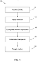
- FIG. 1 is a block diagram illustrating a method 10 of treatment not part of the invention.
- the method 10 includes accessing 12 a cavity from which a tissue mass has been removed.
- a non-chemical stimulus is mechanically applied 14 within the cavity.
- the stimulus upregulates 16 expression of a cell surface marker of a target cell type that is within the cavity along with a plurality of non-target cell types.
- the method 10 includes administering 18 a therapeutic.
- the therapeutic preferentially targets 20 the target cell type for which expression of the cell surface marker has been upregulated.
- the target cell type is a cancer cell and the plurality of non-target cell types are non-cancerous cells.
- the cell surface marker is a cell surface protein and the therapeutic comprises an antibody that binds to the cell surface protein.
- the stimulus includes RF energy and is applied by insertion of a device into the resection cavity. The device may be used to deliver both the stimulus and the therapeutic.
- the device is used for RF ablation of marginal tissue within a resection cavity after a lumpectomy. After a breast cancer tumor is removed, the device is inserted into the resulting cavity in the breast. The device is operated to ablate any cancerous cells in the marginal tissue in the cavity. The ablation has a primary effect of directly killing cancerous cells in the marginal tissue. The ablation also has the effect of upregulating expression the PD-1 cell surface protein. It may be found that this effect involves differential expression in that PD-1 expression is upregulated in cancer cells more than in healthy cells. It also may be found that this effect is delocalized in that PD-1 expression is upregulated within the marginal tissue as well is in cells distant from that location. Thus to ensure complete clearance of the breast cancer, after the lumpectomy, not only is the marginal tissue ablated, but an anti-PD-1 therapeutic is administered. Such a treatment method may be performed using a device or system of the disclosure.
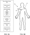
- FIGS. 2A and 2B are schematic illustrations of an ablation system 100 for providing ablation of a target tissue in a patient 102 to thereby upregulate expression of a cell surface marker and/or protein including enzyme of a target cell type along with a plurality of non-target cell types and for delivering a therapeutic that preferentially targets the target cell type for which expression of the cell surface marker has been upregulated.
- the ablation system 100 generally includes an ablation device 104, which includes a probe assembly having a distal tip or portion 106 and an elongated catheter shaft 107 to which the distal tip 106 is connected.
- the catheter shaft 107 may generally include a nonconductive elongated member including a fluid delivery lumen, in addition to other lumens as described in greater detail herein.
- the ablation device 104 may further be coupled to a device controller 108 and an ablation generator 110 over an electrical connection (electrical line 124 shown in FIG. 3 ), an irrigation pump or drip 112 over a fluid connection (fluid line 128 shown in FIG. 3 ), and an inflation source 114 over a connection (connection line 132 shown in FIG. 3 ).
- the device controller 108 may be used to control the emission of energy from one or more conductive members or wires of the device 104 to result in ablation.
- the controller 108 may also be configured to control delivery of fluid to the distal tip 106 so as to control subsequent weeping of fluid from the distal tip 106 during an RF ablation procedure.
- the device controller 108 may be configured to control the inflation source 114 the thereby control inflation of an expandable inner balloon member housed within the distal tip 106 to further assist in the weeping of fluid from the distal tip 106, as will be described in greater detail herein.
- the ablation generator 110 may generally provide RF energy (e.g., electrical energy in the radiofrequency (RF) range (e.g., 350-800 kHz)) to an electrode array of the ablation device 104, as controlled by the device controller 108.
- RF energy e.g., electrical energy in the radiofrequency (RF) range (e.g., 350-800 kHz)
- saline and, in some instances, either concurrently or separately, a drug solution including a therapeutic, may also be released from the distal tip 106.
- the RF energy travels through the blood and tissue of the patient 12 to the return electrode 15 and, in the process, ablates the region(s) of tissues adjacent to portions of the electrode array that have been activated.
- the device controller 108 may include hardware/software configured to provide a user with the ability to control electrical output to the ablation device 104 in a manner so as to control ablation output.
- the ablation device may be configured to operate at least in a "bipolar mode" based on input from a user (e.g., surgeon, clinician, etc.) resulting in the emission of radiofrequency (RF) energy in a bipolar configuration.
- the device 104 may be configured to operate in other modes, such as a "measurement mode", in which data can be collected, such as certain measurements (e.g., temperature, conductivity (impedance), etc.) that can be taken and further used by the controller 18 so as to provide an estimation of the state of tissue during a wound treatment procedure.
- the device controller 108 may include a custom ablation shaping (CAS) system 200 configured to provide a user with custom ablation shaping, which includes the creation of custom, user-defined ablation geometries or profiles from the device 104.
- the CAS system 200 may further be configured to provide ablation status mapping and ablation shaping based on real-time data collection (e.g., measurements) collected by the device.
- controller 108 and CAS system 200 are described in at least U.S. Publication No. 2017/0215951 and U.S. Publication No. 2017/0215947 , the contents of each of which are incorporated by reference herein in their entireties.
- FIG. 3 is a perspective view of one embodiment of an ablation device 104a compatible with the system 100 of FIG. 2A .
- the ablation device 104a includes a probe assembly having an elongated shaft 107, which may be configured as a handle and adapted for manual manipulation.
- the shaft 107 is in the form of a handle having a distal portion or tip 106 extending therefrom and a proximal end 122.
- the proximal end 122 of the device 104a may be coupled to the generator 110, the irrigation pump/drip 112, and the inflation source 114 via connection lines or fittings.
- the device 104a is coupled to the generator 110 via an electrical line 124, coupled to the irrigation pump/drip 112 via a fluid line 128, and coupled to the inflation source 114 via a connection line 132.
- Each of the electrical line 124, fluid line 128, and connection line 132 may include an adaptor end 126, 130, 134 configured to couple the associated lines with a respective interface on the generator 110, irrigation pump/drip 112, and inflation source 114.
- the distal tip 106 may include a neck portion and a generally spheroid body 116 extending distally from the neck.
- the spheroid body 116 may be generally rigid and may maintain a default shape.
- the spheroid body 116 may be configured to transition between a collapsed state and an expanded state.
- the spheroid body 116 may be collapsible to a delivery configuration having a reduced size (e.g., equatorial diameter) relative to the deployed configuration size (e.g., equatorial diameter) of the spheroid body 116.
- the spheroid body 116 includes a non-conductive material (e.g., a polyamide) as a layer on at least a portion of an internal surface, an external surface, or both an external and internal surface.
- a non-conductive material e.g., a polyamide
- the spheroid body 116 is formed from a non-conductive material.
- the spheroid body 116 material can include an elastomeric material or a shape memory material.
- the spheroid body 116 has a diameter (e.g., an equatorial diameter) of about 80 mm or less.
- the spheroid body 116 of the distal tip in a deployed configuration, has an equatorial diameter of 2.0 mm to 60 mm (e.g., 5 mm, 10 mm, 12 mm, 16 mm, 25 mm, 30 mm, 35 mm, 40 mm, 50 mm, and 60 mm).
- the collapsibility of the spheroid body 26 can enable the distal tip to be delivered using standard sheaths (e.g., an 8F introducer sheath).
- the spheroid body 116 need not be collapsible in some procedures, and thus has a relatively rigid body and maintains the default shape.
- the distal tip 116 of the ablation device 14a further includes an electrode array positioned thereon.
- the electrode array includes at least one conductive member 121.
- the electrode array may include a plurality of conductive members 121.
- the plurality of conductive members 121 may extend within the distal tip 106, through one or more ports formed on the spheroid body 116 (i.e., ports 118, 119, 120), and along an external surface of the spheroid body 116.
- the conductive members 121 extend along the longitudinal length of the distal tip 106 and are radially spaced apart (e.g., equidistantly spaced apart) from each other.
- conductive members transmit RF energy from the ablation generator and can be formed of any suitable conductive material (e.g., a metal such as stainless steel, nitinol, or aluminum).
- the conductive members 121 are metal wires. Accordingly, for ease of description, the conductive member(s) will be referred to hereinafter as "conductive wire(s) 121".
- one or more of the conductive wires 121 can be electrically isolated from one or more of the remaining conductive wires 121. This electrical isolation enables various operation modes for the ablation device 104a.
- ablation energy may be supplied to one or more conductive wires 121 in a bipolar mode, a unipolar mode, or a combination bipolar and unipolar mode.
- unipolar mode ablation energy is delivered between one or more conductive wires 121 on the ablation device 104a.
- bipolar mode energy is delivered between at least two of the conductive wires 121, while at least one conductive wire 121 remains neutral.
- at least, one conductive wire functions as a grounded conductive wire (e.g., electrode) by not delivering energy over at least one conductive wire 121.
- the electrosurgical device 104a may further include a user interface (not shown) serving as the device controller 108 and in electrical communication with at least one of the generator 110, the irrigation pump/drip 112, and/or inflation source 114, and the electrosurgical device 104a.
- the user interface may include, for example, selectable buttons for providing an operator with one or more operating modes with respect to controlling the energy emission output of the device 104a.
- selectable buttons may allow a user to control electrical output to the electrosurgical device 104a in a manner so as to control the ablation of a target tissue.
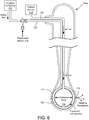
- selectable buttons may provide an operator to control the delivery of fluid from the irrigation pump/drip 112 and/or activation of the inflation source 114 to control inflation of an inner balloon member within the distal tip 106 (shown in FIGS. 6 and 7).
- the spheroid body 116 of the distal tip 106 includes plurality of proximal ports 118, medial ports 119, and distal ports 120 in communication with the at least one lumen of the shaft 107.
- the proximal ports 118 and distal ports 120 generally serve as openings through which conductive wires 121 of the electrode array may pass.
- each of the plurality of wires 121 passes through an associated one of the proximal ports and through a corresponding one of the proximal ports.
- the number of proximal ports 118 and distal ports 120 may generally be equal to the number of conductive wires 121, such that each conductive wire 121 can extend through a different distal port 120, which allows the conductive wires 121 to remain electrically isolated from one another. In other examples, one or more conductive wires can extend through the same distal port 120.
- each conductive wire 121 can extend along an external surface of the spheroid body 116.
- the length of the conductive wire 121 extending along the external surface is at least 20% (e.g., at least, 50%, 60%, 75%, 85%, 90%, or 99%) of the length of the spheroid body 116.
- the conductive wire 121 can then re-enter the spheroid body 116 through a corresponding distal port 120. It should be noted, however, that the conductive wires 121 may enter and pass through any number of ports in any particular arrangement, and need not be limited to a single corresponding set of proximal and distal ports.
- one or more of the conductive wires 121 can be electrically isolated from one or more of the remaining conductive wires, such that the electrical isolation enables various operation modes for the electrosurgical device 104a.
- electrical current may be supplied to one or more conductive wires in a bipolar mode, in which energy is delivered between at least two of the conductive wires, while at least one conductive wire remains neutral.
- one conductive wire functions as a grounded conductive wire (e.g., electrode) by not delivering energy over at least one conductive wire.
- each conductive wire 121 in the electrode array is electrically independent, each conductive wire 121 can be connected in a fashion that allows for impedance measurements using bipolar impedance measurement circuits.
- the conductive wires can be configured in such a fashion that tetrapolar or guarded tetrapolar electrode configurations can be used.
- one pair of conductive wires could function as the current driver and the current return, while another pair of conductive wires could function as a voltage measurement pair.
- a dispersive ground pad can function as current return and voltage references. Their placement dictate the current paths and thus having multiple references can also benefit by providing additional paths for determining the ablation status of the tissue.
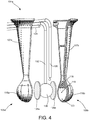
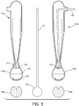
- FIG. 4 is an exploded perspective view of the ablation device 104a and FIG. 5 is a plan view of the ablation device 104a illustrating two halves of the device 104a separated from one another and showing the interior surface of each and internal components.
- the device 104a includes the distal tip 106 formed from two or more pieces (tip halves 106a and 106b) configured to be coupled to one another to form the unitary distal tip 106.
- Each half 106a and 106b includes cooperating neck portions and spheroid bodies 116a, 116b, and shafts 107a, 107b.
- an electrical line 124 may be provided for coupling the conductive wires 121 to the controller 108 and ablation generator 100
- a fluid line 128 may be provided for providing a fluid connection between the irrigation pump/drip 112 and the distal tip 106 so as to provide a conductive fluid (e.g., saline) to the tip 106
- a connection line 132 may be provided for providing a connection between the inflation source 114 and an inflatable member provided within the distal tip 106 (i.e., expandable inner balloon member 136).
- the ablation device 14 is configured to provide RF ablation via a virtual electrode arrangement.
- the device 104a is configured to provide distribution of a fluid along an exterior surface of the distal tip 106 and, upon activation of the electrode array, the fluid may carry, or otherwise promote, energy emitted from the electrode array to the surrounding tissue.
- a conductive fluid such as saline
- the saline may be provided to the distal tip 106 via the fluid line 128, wherein the saline may be distributed through one or more of the ports (e.g., the proximal ports 118, medial ports 119, and/or distal ports 120).
- the saline weeping through the ports and to an outer surface of the distal tip 106 is able to carry electrical current from electrode array, such that energy is promoted from the electrode array to the tissue by way of the saline weeping from the ports, thereby creating a virtual electrode. Accordingly, upon the fluid weeping through the ports, a pool or thin film of fluid is formed on the exterior surface of the distal tip 106 and is configured to ablate surrounding tissue via the electrical current carried from the electrode array.
- the nonconductive spheroid body 116 includes an interior chamber (when the first and second halves 116a, 116b are coupled to one another) retaining at least an inner member 136 and one or more hydrophilic inserts 138a, 138b surrounding the inner member 136.
- the interior chamber of the distal tip 106 is configured to receive and retain a fluid (e.g., saline) therein from a fluid source as well as a drug solution containing the therapeutic, either concurrently or as separate times.
- the hydrophilic inserts 138a, 138b are configured receive and evenly distribute the fluid throughout the interior chamber of the spheroid body 116 by wicking the saline against gravity.
- the hydrophilic inserts 138a and 138b can be formed from a hydrophilic foam material (e.g., hydrophilic polyurethane).
- the inner member 136 may formed from a nonconductive material and may be shaped and sized so as to maintain the hydrophilic inserts 138a, 138b in sufficient contact with the interior surface of the spheroid body 116, and specifically in contact with the one or more ports, such that the hydrophilic inserts 138a, 138b provide uniformity of saline distribution to the ports.
- the inner member 136 may have a generally spherical body, corresponding to the interior contour of the chamber of the spheroid body 136.
- the inner member 136 may be expandable from a collapsed configuration to an expanded configuration (i.e., the inner member may be in the form of an expandable balloon).
- the inner balloon member 136 is in fluid communication with the connection line 132 coupled to the inflation source 114. Accordingly, the inflatable balloon member 136 is in fluid communication with the inflation source 114 via the connection line 132, such that, when the inflation source is activated, the inner balloon member 136 inflates and transitions from a collapsed configuration (shown in FIG. 6 ) to an expanded configuration (shown in FIG. 7).
- the inner balloon member 136 Upon inflation, the inner balloon member 136 is shaped and sized so as to maintain the hydrophilic insert 138 in contact with the interior surface of the spheroid body 116, and specifically in contact with the one or more ports, such that the hydrophilic insert 137 provides uniformity of saline distribution to the ports.
- the inner balloon member Upon inflating the inner balloon member 136 into the expanded configuration, the inner balloon member applies a force upon the surrounding hydrophilic insert 138, thereby forcing the insert 138 against an interior surface of spheroid body 116 and causing the saline solution and/or drug solution to be squeezed out of the hydrophilic insert 136 and through the plurality of ports.
- all of the ports may be configured to allow for passage of fluid from the inserts 138a, 1388b to the exterior surface of the distal tip 106.
- only the medial ports 119 may allow for fluid passage, while the proximal and distal ports 118, 120 may be blocked via a heat shrink or other occlusive material.
- FIGS. 6 and 7 area schematic illustrations of the ablation device of FIG. 3 , partly in section, illustrating delivery of fluid from an irrigation pump/drip, which may include a therapeutic, to a hydrophilic insert (foam-like material) within the interior chamber of the distal portion of the device, wherein the fluid can be subsequently distributed to an exterior surface of the distal portion in response to inflation of an inner balloon member to an expanded configuration, thereby resulting in a virtual electrode arrangement upon activation of one or more portions of an electrode array and delivery of the therapeutic to the surrounding tissue.
- FIG. 6 illustrates the inner balloon member in a collapsed, or at least partially-collapsed, configuration.
- FIG. 7 illustrates the inner balloon member in an expanded configuration, which in turn results in application of force upon the surrounding hydrophilic insert to thereby force fluid from the hydrophilic insert through one or more ports and to an exterior surface of the distal portion of the device
- the therapeutic can be provided in a fluid form (i.e., drug solution) such that the therapeutic can be delivered either concurrently with the saline, or separately, into the interior chamber of the distal tip 106.
- a fluid form i.e., drug solution
- the arrangement of the inflatable inner balloon member 136 and hydrophilic insert 138 ensures a uniform delivery of the therapeutic to the marginal tissue in the resection cavity and also minimizes wastage of the drug, by precisely delivering a controlled dose to the marginal tissue.
- saline is provided for RF ablation and a therapeutic is administered under different conditions.
- the saline may be delivered at a pressure that approximates the pressure of the cavity environment.
- pressure may be increased to aid in delivering the therapeutic into the subject.
- Embodiments of the ablation systems and device are provided that include features for the delivery of a therapeutic and mechanical application of a stimulus that causes differential expression of a marker by cell type.
- Systems and devices can be used in methods that leverage a connection between the differentially expressed marker and the therapeutic to provide effective treatment methods. For example, where the therapeutic attacks cells expressing the marker, and the marker can be differentially expressed in diseased cells, systems and devices are useful for effectively treating the disease.
- the mechanical systems and devices for delivering a stimulus can include features for delivering the therapeutic.
- Any suitable non-chemical stimulus may be provided within the cavity such as RF energy, heat, cryoablation, mechanical ablation, electrocautery, others, or combinations thereof.
- the stimulus upregulates expression of a cell surface marker of a target cell type.
- the target cell type could be, for example, blood cells, bacterial cells, cells of a certain tissue type, cells of a certain genotype or karyotype, cells of a parasite, or cells affected by a medical condition.
- the target cell type is cancer cells and the non-target cell types are healthy cells in the subject.
- Suitable cell surface markers may be upregulated using the disclosed devices.
- Suitable markers include, but are not limited to, biomolecules comprising polypeptides, proteins, carbohydrates, lipids, glycoproteins, ribonucleoproteins, lipoproteins, glycolipids and fragments thereof.
- the marker comprises a membrane protein, including polypeptides, glycoproteins and lipoproteins.
- the marker may be a transmembrane protein or may be bound to a transmembrane protein or membrane lipid, for example.
- the marker may be a cell surface receptor.
- the receptor may comprise a tyrosine kinase receptor, such as an erythropoietin receptor, an insulin receptor, a hormone receptor or a cytokine receptor.
- Preferred tyrosine kinases include fibroblast growth factor (FGF) receptors, platelet-derived growth factor (PDGF) receptors, nerve growth Factor (NGF) receptors, brain-derived neurotrophic Factor (BDNF) receptors, and neurotrophin-3 (NT-3) receptors, and neurotrophin-4 (NT-4) receptors.
- the receptor may comprise a guanylyl cyclase receptor such as GC-A & GC-B, a receptor for atrial-natriuretic peptide (ANP) and other natriuretic peptides or GC-C, a guanylin receptor, a member of the ErbB or epidermal growth factor receptor (EGFR) family, e.g.
- GPCR G protein-coupled receptor
- a G protein-coupled receptor such as a muscarinic acetylcholine receptor, an adenosine receptor, an adrenergic receptor, a GABA-B receptor, an angiotensin receptor, a cannabinoid receptor, a cholecystokinin receptor, a dopamine receptor, a glucagon receptor, a histamine receptor, a olfactory receptor, a opioid receptor, a rhodopsin receptor, a secretin receptor, a serotonin receptor or a somatostatin receptor, an ionotropic receptor, for example a nicotinic acetylcholine receptor, a glycine receptor, a GABA-A or GABA-C receptor, a glutamate receptor, an NMDA receptor, an ionotropic receptor, for example a nicotinic acetylcholine receptor, a g
- the cell surface marker may be a cluster of differentiation antigen, e.g. CD2, CD3, CD4, CD5, CD7, CD8, CD9, CD10, CD11, CD13, CD15, CD16, CD20, CD21, CD22, CD23, CD24, CD25, CD33, CD34, CD36, CD37, CD38, CD41, CD42, CD44, CD45, CD52, CD57, CD60, CD61, CD64, CD71, CD79, CD80, CD95, CD103, CD117, CD122, CD133, CD134, CD138 or CD154.
- the marker is correlated with a disease, preferably a human or animal disease.
- the marker may be associated with cancer, for example breast or ovarian cancer.
- Suitable markers may include: CA-125 (MUC-16), CA19-9, HER-2, also known as HER2/neu, erbB-2, EGFR2, wADAM1O, ⁇ V ⁇ integrin, Caveolin- 1, CD 147, CD36, CD63, CD81, Claudin-3, Claudin-4, Desmocollin- 1, EGFR, EGFRvIII, EMP-2, EpCAM, ErbB2, GP I b, HLA-DR, Hsp70, Hsp90, MFG-E8, Rab 13, PSA, PSAP, PSMA, Hep Par 1, AFP, CAM 5.2, CD1O, Vimentin, RCC, and EMA, Ae 1/3, CAM 5.2, CK19, CEA, PSA, PSAP, PSMA, Thyroglobulin, Calictonin
- the therapeutic comprises an antibody that binds to the cell surface protein.
- the cell surface protein is PD-1.
- the stimulus is applied to ablate tissue within the cavity.
- Ablation of liver metastases can cause upregulated expression of PD-L1 on primary colorectal tumors.
- Devices of the disclosure may cause upregulation of PD-L1 in distant tumor cells systemically, especially in lymph nodes and other micro metastasis.
- PD-1 inhibitors are used as the therapeutic, e.g., in early breast cancer. For background, see Shi, 2016, PD-1 blockade boosts radiofrequency ablation-elicited adaptive immune responses against tumor, Clin Can Res 22(5):1173-1184 , incorporated by reference.
- the device 104a can provide both RF ablation and drug delivery.
- the hydrophilic insert 138 distributes saline uniformly for the RF Ablation, so it should for drug as well.
- the inner balloon member 136 allows the device to minimize drug waste by effectively squeezing hydrophilic insert 138.
- Devices of the disclosure may be beneficial for combination therapy for Triple negative and Her2+ patients who typically have poor outcomes.
- HSP70 overexpression is correlated with poor differentiation, p53 mutation, and a poor prognosis.
- HSP90 overexpression in breast tumors is also correlated with a poor prognosis.
- HSP70 overexpression has been shown to indicate resistance to chemotherapy, radiation, and ablation in breast tumors.
- Evidence suggests HSP70 expression is induced by RFA, specifically in the transition zone.
- Other markers that may respond to ablation may include CRP and IL6.
Landscapes
- Health & Medical Sciences (AREA)
- Surgery (AREA)
- Engineering & Computer Science (AREA)
- Life Sciences & Earth Sciences (AREA)
- Medical Informatics (AREA)
- General Health & Medical Sciences (AREA)
- Nuclear Medicine, Radiotherapy & Molecular Imaging (AREA)
- Plasma & Fusion (AREA)
- Biomedical Technology (AREA)
- Heart & Thoracic Surgery (AREA)
- Physics & Mathematics (AREA)
- Molecular Biology (AREA)
- Animal Behavior & Ethology (AREA)
- Otolaryngology (AREA)
- Public Health (AREA)
- Veterinary Medicine (AREA)
- Cardiology (AREA)
- Neurology (AREA)
- Neurosurgery (AREA)
- Surgical Instruments (AREA)
- Measurement And Recording Of Electrical Phenomena And Electrical Characteristics Of The Living Body (AREA)
Claims (14)
- Medizinische Vorrichtung (104) zum Behandeln von erkranktem Gewebe (102), wobei die Vorrichtung umfasst:eine Sondenanordnung, umfassend:einen nicht leitfähigen Griff, der eine erste Fluidleitung (128) zum Aufnehmen mindestens eines von einem ersten Fluid und/oder einem Therapeutikum und eine zweite Fluidleitung zum Aufnehmen eines zweiten Fluids umfasst;einen nicht leitfähigen distalen Abschnitt (106), der sich von dem Griff aus erstreckt, wobei der distale Abschnitt (106) einen starren kugelförmigen Körper (116) mit einem festgelegten Durchmesser umfasst, der eine Innenkammer in Fluidkommunikation mit der ersten Fluidleitung umfasst und konfiguriert ist, um mindestens eines von dem ersten Fluid und dem Therapeutikum davon aufzunehmen, wobei der starre kugelförmige Körper (116) auch eine Vielzahl von Öffnungen (118, 119, 120) definiert, die konfiguriert sind, um den Durchgang mindestens eines von dem ersten Fluid und dem Therapeutikum aus der Innenkammer zu einer Außenfläche des starren kugelförmigen Körpers (116) zu erlauben;ein expandierbares inneres Ballonelement (136), das im Innern der Innenkammer und in Fluidkommunikation mit der zweiten Fluidleitung angeordnet ist und konfiguriert ist, um als Reaktion auf die Abgabe eines zweiten Fluids aus der zweiten Fluidleitung von einer kollabierten Konfiguration in eine expandierte Konfiguration überzugehen; undeine hydrophile Einlage (138), die im Innern der Innenkammer angeordnet ist, wobei die hydrophile Einlage (138) im Innern der Innenkammer zwischen mindestens einem Abschnitt einer Außenfläche des inneren Ballonelements (136) und einer Innenfläche des starren kugelförmigen Körpers (116) an Ort und Stelle gehalten wird, wobei die hydrophile Einlage (138) konfiguriert ist, um mindestens eines von dem ersten Fluid und dem Therapeutikum aufzunehmen und gleichmäßig auf die Vielzahl von Öffnungen (118, 119, 120) zu verteilen;ein Elektrodenfeld, das eine Vielzahl von unabhängigen leitfähigen Drähten (121) umfasst, die jeweils eine Länge umfassen, die entlang der Außenfläche des starren kugelförmigen Körpers (116) positioniert ist; undein aktives Mittel zum Steuern des Übergangs des inneren Ballonelements (136) zwischen der kollabierten Konfiguration und der expandierten Konfiguration und eine Vielzahl von Konfigurationen dazwischen, wobei das aktive Mittel betriebsfähig ist, um das innere Ballonelement (136) während eines Ablationsvorgangs an einem Zielgewebe (102) auf einen ersten Durchmesser und für die Abgabe des Therapeutikums an das Zielgewebe (102) auf einen zweiten, größeren Durchmesser aufzublasen.
- Medizinische Vorrichtung (104) nach Anspruch 1, wobei das erste Fluid ein leitfähiges Fluid ist, und wobei jeder der Vielzahl von Drähten, oder eine oder mehrere Gruppen einer Kombination von Drähten, konfiguriert ist, um einen elektrischen Strom zu empfangen und Energie, die von dem ersten Fluid getragen werden soll, das durch eine oder mehrere der Vielzahl von Öffnungen (118, 119, 120) geht, zur Ablation eines Zielgewebes (102) zu leiten.
- Medizinische Vorrichtung (104) nach Anspruch 2, ferner umfassend das Therapeutikum, das im Innern der hydrophilen Einlage (138) verteilt wird.
- Medizinische Vorrichtung (104) nach Anspruch 3, wobei das Therapeutikum gegen Zellen wirkt, die einen Marker aufweisen, der durch die Ablation hochreguliert wird, und wahlweise oder bevorzugt wobei der Zellenoberflächenmarker ein Zellenoberflächenprotein ist.
- Medizinische Vorrichtung (104) nach Anspruch 4, wobei das Therapeutikum einen Antikörper umfasst, der an das Zellenoberflächenprotein bindet, und wahlweise oder bevorzugt wobei der Marker PD-1 ist und das Therapeutikum einen Anti-PD-1-Antikörper umfasst.
- Medizinische Vorrichtung (104) nach Anspruch 3, wobei das Therapeutikum gegen Zellen wirkt, die ein Protein aufweisen, das ein Enzym umfasst, das durch die Ablation hochreguliert wird, und wahlweise oder bevorzugt wobei das Enzym Thymidinphosphorylase ist.
- Medizinische Vorrichtung (104) nach Anspruch 1, wobei, wenn das innere Ballonelement (136) auf den zweiten, größeren Durchmesser aufgeblasen wird, das innere Ballonelement (136) eine Kraft auf die umgebende hydrophile Einlage (138) ausübt, die ausreicht, um zu bewirken, dass die hydrophile Einlage (138) zwischen der Außenfläche des inneren Ballonelements (136) und der Innenfläche des starren kugelförmigen Körpers (116) komprimiert wird, und ferner um mindestens eines von dem ersten Fluid und dem Therapeutikum aus der hydrophilen Einlage (138) und über mindestens eine der Vielzahl von Öffnungen (118, 119, 120) auszustoßen.
- Medizinische Vorrichtung (104) nach Anspruch 2, wobei die Vorrichtung zur gleichzeitigen Ablation von Zielgewebe (102) und zur Abgabe des Therapeutikums durch eine oder mehrere der Vielzahl von Öffnungen (118, 119, 120) betriebsfähig ist.
- Medizinische Vorrichtung (104) nach Anspruch 2, wobei jeder der Vielzahl von Drähten konfiguriert ist, um beim Empfang des elektrischen Stroms Funkfrequenz- (RF) Energie zu leiten.
- Medizinische Vorrichtung (104) nach Anspruch 1, wobei die Vielzahl von Öffnungen (118, 119, 120) eine Vielzahl von proximalen Öffnungen (118) und distalen Öffnungen (120) umfasst, wobei jeder der Vielzahl von Drähten durch mindestens eine der proximalen Öffnungen (118) und durch eine entsprechende der distalen Öffnungen (120), die zu der proximalen Öffnung distal ist, geht, wobei jede der Vielzahl von proximalen Öffnungen (118) einer getrennten der Vielzahl von distalen Öffnungen (120) entspricht, so dass ein Abschnitt des leitfähigen Drahts (121), der durch eine Gruppe von entsprechenden proximalen und distalen Öffnungen (120) geht, eine Länge aufweist, die sich entlang der Außenfläche des distalen Abschnitts (106) zwischen den entsprechenden proximalen und distalen Öffnungen (120) erstreckt.
- Medizinische Vorrichtung (104) nach Anspruch 10, wobei sich der Draht entlang mindestens 20 % der Länge des distalen Abschnitts (106) und entlang der Außenfläche des distalen Abschnitts (106) erstreckt.
- Medizinische Vorrichtung (104) nach Anspruch 10, wobei jeder der Vielzahl von leitfähigen Drähten (121) durch eine andere distale Öffnung oder eine andere proximale Öffnung geht.
- Medizinische Vorrichtung (104) nach Anspruch 1, wobei das erste Fluid ein leitfähiges Fluid ist.
- Medizinische Vorrichtung (104) nach Anspruch 1, wobei die Vielzahl von Öffnungen (118, 119, 120) eine oder mehrere mediale Anschlüsse (119) auf dem nicht leitfähigen distalen Abschnitt (106) umfasst und konfiguriert ist, um den Durchgang mindestens eines von dem ersten Fluid und dem Therapeutikum von der Innenkammer zu einer Außenfläche des nicht leitfähigen distalen Abschnitts (106) zu erlauben.
Applications Claiming Priority (2)
| Application Number | Priority Date | Filing Date | Title |
|---|---|---|---|
| US201662409103P | 2016-10-17 | 2016-10-17 | |
| PCT/US2017/056754 WO2018075389A1 (en) | 2016-10-17 | 2017-10-16 | Treatment devices and methods |
Publications (3)
| Publication Number | Publication Date |
|---|---|
| EP3525703A1 EP3525703A1 (de) | 2019-08-21 |
| EP3525703A4 EP3525703A4 (de) | 2020-04-22 |
| EP3525703B1 true EP3525703B1 (de) | 2021-07-07 |
Family
ID=61902911
Family Applications (1)
| Application Number | Title | Priority Date | Filing Date |
|---|---|---|---|
| EP17862591.9A Active EP3525703B1 (de) | 2016-10-17 | 2017-10-16 | Behandlungsvorrichtungen |
Country Status (4)
| Country | Link |
|---|---|
| US (3) | US10070921B2 (de) |
| EP (1) | EP3525703B1 (de) |
| JP (1) | JP2019536509A (de) |
| WO (1) | WO2018075389A1 (de) |
Families Citing this family (8)
| Publication number | Priority date | Publication date | Assignee | Title |
|---|---|---|---|---|
| EP3288478B1 (de) | 2015-04-29 | 2019-12-25 | Innoblative Designs, Inc. | Ablation von kavitärem gewebe |
| JP6933857B2 (ja) | 2015-10-29 | 2021-09-08 | イノブレイティブ デザインズ, インコーポレイテッド | 網球状組織アブレーションデバイスおよび方法 |
| WO2017136261A1 (en) | 2016-02-02 | 2017-08-10 | Innoblative Designs, Inc. | Cavitary tissue ablation system |
| WO2017151431A1 (en) | 2016-03-01 | 2017-09-08 | Innoblative Designs, Inc. | Resecting and coagulating tissue |
| EP3525703B1 (de) | 2016-10-17 | 2021-07-07 | Innoblative Designs, Inc. | Behandlungsvorrichtungen |
| EP3538000A4 (de) | 2016-11-08 | 2020-04-01 | Innoblative Designs, Inc. | Elektrochirurgische gewebe- und gefässversiegelungsvorrichtung |
| US11786297B2 (en) | 2017-07-26 | 2023-10-17 | Innoblative Designs, Inc. | Minimally invasive articulating assembly having ablation capabilities |
| US20210228258A1 (en) | 2018-06-06 | 2021-07-29 | Robert F. Rioux | Portable wound treatment system |
Family Cites Families (216)
| Publication number | Priority date | Publication date | Assignee | Title |
|---|---|---|---|---|
| US5370675A (en) | 1992-08-12 | 1994-12-06 | Vidamed, Inc. | Medical probe device and method |
| US4699147A (en) | 1985-09-25 | 1987-10-13 | Cordis Corporation | Intraventricular multielectrode cardial mapping probe and method for using same |
| US4979948A (en) | 1989-04-13 | 1990-12-25 | Purdue Research Foundation | Method and apparatus for thermally destroying a layer of an organ |
| US4976711A (en) | 1989-04-13 | 1990-12-11 | Everest Medical Corporation | Ablation catheter with selectively deployable electrodes |
| US5045056A (en) | 1989-09-15 | 1991-09-03 | Behl Robert S | Method and device for thermal ablation of hollow body organs |
| US5117828A (en) | 1989-09-25 | 1992-06-02 | Arzco Medical Electronics, Inc. | Expandable esophageal catheter |
| US5163938A (en) | 1990-07-19 | 1992-11-17 | Olympus Optical Co., Ltd. | High-frequency surgical treating device for use with endoscope |
| US5100423A (en) | 1990-08-21 | 1992-03-31 | Medical Engineering & Development Institute, Inc. | Ablation catheter |
| US5697909A (en) | 1992-01-07 | 1997-12-16 | Arthrocare Corporation | Methods and apparatus for surgical cutting |
| US5443470A (en) | 1992-05-01 | 1995-08-22 | Vesta Medical, Inc. | Method and apparatus for endometrial ablation |
| US5562720A (en) | 1992-05-01 | 1996-10-08 | Vesta Medical, Inc. | Bipolar/monopolar endometrial ablation device and method |
| US5772590A (en) | 1992-06-30 | 1998-06-30 | Cordis Webster, Inc. | Cardiovascular catheter with laterally stable basket-shaped electrode array with puller wire |
| US5672153A (en) | 1992-08-12 | 1997-09-30 | Vidamed, Inc. | Medical probe device and method |
| US5486161A (en) | 1993-02-02 | 1996-01-23 | Zomed International | Medical probe device and method |
| CA2144973C (en) | 1992-09-23 | 2010-02-09 | Graydon Ernest Beatty | Endocardial mapping system |
| US5471982A (en) | 1992-09-29 | 1995-12-05 | Ep Technologies, Inc. | Cardiac mapping and ablation systems |
| US5334193A (en) | 1992-11-13 | 1994-08-02 | American Cardiac Ablation Co., Inc. | Fluid cooled ablation catheter |
| US5893847A (en) | 1993-03-16 | 1999-04-13 | Ep Technologies, Inc. | Multiple electrode support structures with slotted hub and hoop spline elements |
| US6832996B2 (en) | 1995-06-07 | 2004-12-21 | Arthrocare Corporation | Electrosurgical systems and methods for treating tissue |
| US5840076A (en) | 1996-04-12 | 1998-11-24 | Ep Technologies, Inc. | Tissue heating and ablation systems and methods using electrode structures with distally oriented porous regions |
| US5928229A (en) | 1993-11-08 | 1999-07-27 | Rita Medical Systems, Inc. | Tumor ablation apparatus |
| US5728143A (en) | 1995-08-15 | 1998-03-17 | Rita Medical Systems, Inc. | Multiple antenna ablation apparatus and method |
| US5536267A (en) | 1993-11-08 | 1996-07-16 | Zomed International | Multiple electrode ablation apparatus |
| US5472441A (en) | 1993-11-08 | 1995-12-05 | Zomed International | Device for treating cancer and non-malignant tumors and methods |
| US5683384A (en) | 1993-11-08 | 1997-11-04 | Zomed | Multiple antenna ablation apparatus |
| US5599346A (en) | 1993-11-08 | 1997-02-04 | Zomed International, Inc. | RF treatment system |
| US6071280A (en) | 1993-11-08 | 2000-06-06 | Rita Medical Systems, Inc. | Multiple electrode ablation apparatus |
| US5429605A (en) | 1994-01-26 | 1995-07-04 | Target Therapeutics, Inc. | Microballoon catheter |
| WO1995029737A1 (en) | 1994-05-03 | 1995-11-09 | Board Of Regents, The University Of Texas System | Apparatus and method for noninvasive doppler ultrasound-guided real-time control of tissue damage in thermal therapy |
| US6009877A (en) | 1994-06-24 | 2000-01-04 | Edwards; Stuart D. | Method for treating a sphincter |
| US5885278A (en) | 1994-10-07 | 1999-03-23 | E.P. Technologies, Inc. | Structures for deploying movable electrode elements |
| US6063081A (en) | 1995-02-22 | 2000-05-16 | Medtronic, Inc. | Fluid-assisted electrocautery device |
| US5897553A (en) | 1995-11-02 | 1999-04-27 | Medtronic, Inc. | Ball point fluid-assisted electrocautery device |
| US6409722B1 (en) | 1998-07-07 | 2002-06-25 | Medtronic, Inc. | Apparatus and method for creating, maintaining, and controlling a virtual electrode used for the ablation of tissue |
| US5868740A (en) | 1995-03-24 | 1999-02-09 | Board Of Regents-Univ Of Nebraska | Method for volumetric tissue ablation |
| US6837888B2 (en) | 1995-06-07 | 2005-01-04 | Arthrocare Corporation | Electrosurgical probe with movable return electrode and methods related thereto |
| US7179255B2 (en) | 1995-06-07 | 2007-02-20 | Arthrocare Corporation | Methods for targeted electrosurgery on contained herniated discs |
| US5672173A (en) | 1995-08-15 | 1997-09-30 | Rita Medical Systems, Inc. | Multiple antenna ablation apparatus and method |
| US5782827A (en) | 1995-08-15 | 1998-07-21 | Rita Medical Systems, Inc. | Multiple antenna ablation apparatus and method with multiple sensor feedback |
| US5913855A (en) | 1995-08-15 | 1999-06-22 | Rita Medical Systems, Inc. | Multiple antenna ablation apparatus and method |
| US6689127B1 (en) | 1995-08-15 | 2004-02-10 | Rita Medical Systems | Multiple antenna ablation apparatus and method with multiple sensor feedback |
| US5863290A (en) | 1995-08-15 | 1999-01-26 | Rita Medical Systems | Multiple antenna ablation apparatus and method |
| US5672174A (en) | 1995-08-15 | 1997-09-30 | Rita Medical Systems, Inc. | Multiple antenna ablation apparatus and method |
| US5980517A (en) | 1995-08-15 | 1999-11-09 | Rita Medical Systems, Inc. | Cell necrosis apparatus |
| US6053937A (en) | 1995-08-15 | 2000-04-25 | Rita Medical Systems, Inc. | Multiple electrode ablation apparatus and method with cooling element |
| US5925038A (en) | 1996-01-19 | 1999-07-20 | Ep Technologies, Inc. | Expandable-collapsible electrode structures for capacitive coupling to tissue |
| US6071278A (en) | 1996-02-28 | 2000-06-06 | Ep Technologies, Inc. | Tissue heating and ablation systems and methods using porous electrode structures with specified electrical resistivities |
| US5891136A (en) | 1996-01-19 | 1999-04-06 | Ep Technologies, Inc. | Expandable-collapsible mesh electrode structures |
| US5846239A (en) | 1996-04-12 | 1998-12-08 | Ep Technologies, Inc. | Tissue heating and ablation systems and methods using segmented porous electrode structures |
| US5868736A (en) | 1996-04-12 | 1999-02-09 | Ep Technologies, Inc. | Systems and methods to control tissue heating or ablation with porous electrode structures |
| US5961513A (en) | 1996-01-19 | 1999-10-05 | Ep Technologies, Inc. | Tissue heating and ablation systems and methods using porous electrode structures |
| US5871483A (en) | 1996-01-19 | 1999-02-16 | Ep Technologies, Inc. | Folding electrode structures |
| WO1997025919A1 (en) | 1996-01-19 | 1997-07-24 | Ep Technologies, Inc. | Systems and methods for heating and ablating tissue using multifunctional electrode structures |
| US6475213B1 (en) | 1996-01-19 | 2002-11-05 | Ep Technologies, Inc. | Method of ablating body tissue |
| US6309352B1 (en) | 1996-01-31 | 2001-10-30 | Board Of Regents, The University Of Texas System | Real time optoacoustic monitoring of changes in tissue properties |
| US6032077A (en) | 1996-03-06 | 2000-02-29 | Cardiac Pathways Corporation | Ablation catheter with electrical coupling via foam drenched with a conductive fluid |
| US5868776A (en) | 1996-09-03 | 1999-02-09 | Ideas For Medicine, Inc. | Overlay dual balloon catheter and method for use thereof |
| US6464697B1 (en) | 1998-02-19 | 2002-10-15 | Curon Medical, Inc. | Stomach and adjoining tissue regions in the esophagus |
| US6050992A (en) | 1997-05-19 | 2000-04-18 | Radiotherapeutics Corporation | Apparatus and method for treating tissue with multiple electrodes |
| US5938660A (en) | 1997-06-27 | 1999-08-17 | Daig Corporation | Process and device for the treatment of atrial arrhythmia |
| US6251109B1 (en) | 1997-06-27 | 2001-06-26 | Daig Corporation | Process and device for the treatment of atrial arrhythmia |
| US6241666B1 (en) | 1997-07-03 | 2001-06-05 | Cardiac Pathways Corp. | Ablation catheter tip with a buffer layer covering the electrode |
| US6917834B2 (en) | 1997-12-03 | 2005-07-12 | Boston Scientific Scimed, Inc. | Devices and methods for creating lesions in endocardial and surrounding tissue to isolate focal arrhythmia substrates |
| US6258087B1 (en) | 1998-02-19 | 2001-07-10 | Curon Medical, Inc. | Expandable electrode assemblies for forming lesions to treat dysfunction in sphincters and adjoining tissue regions |
| US20100114087A1 (en) | 1998-02-19 | 2010-05-06 | Edwards Stuart D | Methods and devices for treating urinary incontinence |
| US6331166B1 (en) | 1998-03-03 | 2001-12-18 | Senorx, Inc. | Breast biopsy system and method |
| US6142993A (en) | 1998-02-27 | 2000-11-07 | Ep Technologies, Inc. | Collapsible spline structure using a balloon as an expanding actuator |
| US6312429B1 (en) | 1998-09-01 | 2001-11-06 | Senorx, Inc. | Electrosurgical lesion location device |
| US6522930B1 (en) | 1998-05-06 | 2003-02-18 | Atrionix, Inc. | Irrigated ablation device assembly |
| US6508815B1 (en) | 1998-05-08 | 2003-01-21 | Novacept | Radio-frequency generator for powering an ablation device |
| US6802841B2 (en) | 1998-06-04 | 2004-10-12 | Curon Medical, Inc. | Systems and methods for applying a selected treatment agent into contact with tissue to treat sphincter dysfunction |
| US7198635B2 (en) | 2000-10-17 | 2007-04-03 | Asthmatx, Inc. | Modification of airways by application of energy |
| US6494902B2 (en) | 1998-07-07 | 2002-12-17 | Medtronic, Inc. | Method for creating a virtual electrode for the ablation of tissue and for selected protection of tissue during an ablation |
| US6537272B2 (en) | 1998-07-07 | 2003-03-25 | Medtronic, Inc. | Apparatus and method for creating, maintaining, and controlling a virtual electrode used for the ablation of tissue |
| US6537248B2 (en) | 1998-07-07 | 2003-03-25 | Medtronic, Inc. | Helical needle apparatus for creating a virtual electrode used for the ablation of tissue |
| US6706039B2 (en) | 1998-07-07 | 2004-03-16 | Medtronic, Inc. | Method and apparatus for creating a bi-polar virtual electrode used for the ablation of tissue |
| US6112123A (en) | 1998-07-28 | 2000-08-29 | Endonetics, Inc. | Device and method for ablation of tissue |
| US6053913A (en) | 1998-09-10 | 2000-04-25 | Tu; Lily Chen | Rapid exchange stented balloon catheter having ablation capabilities |
| US6036689A (en) | 1998-09-24 | 2000-03-14 | Tu; Lily Chen | Ablation device for treating atherosclerotic tissues |
| US7364577B2 (en) | 2002-02-11 | 2008-04-29 | Sherwood Services Ag | Vessel sealing system |
| US6123718A (en) | 1998-11-02 | 2000-09-26 | Polymerex Medical Corp. | Balloon catheter |
| JP2002537913A (ja) | 1999-03-02 | 2002-11-12 | アトリオニクス・インコーポレーテツド | バルーンとセンサーを有する心房改質器 |
| US6425877B1 (en) | 1999-04-02 | 2002-07-30 | Novasys Medical, Inc. | Treatment of tissue in the digestive circulatory respiratory urinary and reproductive systems |
| US6221071B1 (en) | 1999-06-04 | 2001-04-24 | Scimed Life Systems, Inc. | Rapid electrode deployment |
| US8597290B2 (en) | 1999-07-14 | 2013-12-03 | Mederi Therapeutics | Method for treating fecal incontinence |
| ITMI991608A1 (it) | 1999-07-21 | 2001-01-21 | Thermo Med 2000 Kft | Sonda elettrochirurgica per il trattamento di tumori mediante radiofrequenza |
| US20020087155A1 (en) | 1999-08-30 | 2002-07-04 | Underwood Ronald A. | Systems and methods for intradermal collagen stimulation |
| CA2825425C (en) | 1999-11-16 | 2016-03-22 | Covidien Lp | System and method of treating abnormal tissue in the human esophagus |
| US20040215235A1 (en) | 1999-11-16 | 2004-10-28 | Barrx, Inc. | Methods and systems for determining physiologic characteristics for treatment of the esophagus |
| US20060095032A1 (en) | 1999-11-16 | 2006-05-04 | Jerome Jackson | Methods and systems for determining physiologic characteristics for treatment of the esophagus |
| US20090292177A1 (en) | 1999-12-27 | 2009-11-26 | Eggers Philip E | Method and apparatus for positioning a tissue recovery instrument in confronting adjacency with a target tissue volume |
| US6451017B1 (en) | 2000-01-10 | 2002-09-17 | Hydrocision, Inc. | Surgical instruments with integrated electrocautery |
| US6663622B1 (en) | 2000-02-11 | 2003-12-16 | Iotek, Inc. | Surgical devices and methods for use in tissue ablation procedures |
| ES2643763T3 (es) | 2000-03-06 | 2017-11-24 | Salient Surgical Technologies, Inc. | Sistema de suministro de fluido y controlador para dispositivos electroquirúrgicos |
| US6926712B2 (en) | 2000-03-24 | 2005-08-09 | Boston Scientific Scimed, Inc. | Clamp having at least one malleable clamp member and surgical method employing the same |
| US6869430B2 (en) | 2000-03-31 | 2005-03-22 | Rita Medical Systems, Inc. | Tissue biopsy and treatment apparatus and method |
| US6454766B1 (en) | 2000-05-05 | 2002-09-24 | Scimed Life Systems, Inc. | Microporous electrode structure and method of making the same |
| JP2002078809A (ja) | 2000-09-07 | 2002-03-19 | Shutaro Satake | 肺静脈電気的隔離用バルーンカテーテル |
| US7387628B1 (en) | 2000-09-15 | 2008-06-17 | Boston Scientific Scimed, Inc. | Methods and systems for focused bipolar tissue ablation |
| US6638275B1 (en) | 2000-10-05 | 2003-10-28 | Medironic, Inc. | Bipolar ablation apparatus and method |
| US20040087936A1 (en) | 2000-11-16 | 2004-05-06 | Barrx, Inc. | System and method for treating abnormal tissue in an organ having a layered tissue structure |
| US6692466B1 (en) | 2000-12-21 | 2004-02-17 | Advanced Cardiovascular Systems, Inc. | Drug delivery catheter with retractable needle |
| US6743226B2 (en) | 2001-02-09 | 2004-06-01 | Cosman Company, Inc. | Adjustable trans-urethral radio-frequency ablation |
| US6648883B2 (en) | 2001-04-26 | 2003-11-18 | Medtronic, Inc. | Ablation system and method of use |
| JP2005500108A (ja) | 2001-08-15 | 2005-01-06 | リライアント テクノロジーズ,インコーポレイティド | 生物学的組織の熱的切除のための装置と方法 |
| US7615049B2 (en) | 2001-09-19 | 2009-11-10 | Mederi Therapeutics, Inc. | Devices, systems and methods for treating tissue regions of the body |
| US7344533B2 (en) | 2001-09-28 | 2008-03-18 | Angiodynamics, Inc. | Impedance controlled tissue ablation apparatus and method |
| US6770072B1 (en) | 2001-10-22 | 2004-08-03 | Surgrx, Inc. | Electrosurgical jaw structure for controlled energy delivery |
| AU2002366635A1 (en) | 2001-12-10 | 2003-06-23 | The Board Of Trustees Of The University Of Arkansas | Minimally invasive treatment for breast cancer |
| US7769432B2 (en) | 2001-12-10 | 2010-08-03 | Board Of Trustees Of The University Of Arkansas | Minimally invasive diagnosis and treatment for breast cancer |
| US7311708B2 (en) | 2001-12-12 | 2007-12-25 | Tissuelink Medical, Inc. | Fluid-assisted medical devices, systems and methods |
| AU2003218050A1 (en) | 2002-02-11 | 2003-09-04 | Arthrocare Corporation | Electrosurgical apparatus and methods for laparoscopy |
| WO2003068311A2 (en) | 2002-02-13 | 2003-08-21 | Arthrocare Corporation | Electrosurgical apparatus and methods for treating joint tissue |
| US6878149B2 (en) | 2002-03-25 | 2005-04-12 | Acueity, Inc. | Apparatus and method for intraductal abalation |
| US7141055B2 (en) | 2002-04-24 | 2006-11-28 | Surgical Connections, Inc. | Resection and anastomosis devices and methods |
| US6780183B2 (en) | 2002-09-16 | 2004-08-24 | Biosense Webster, Inc. | Ablation catheter having shape-changing balloon |
| US7306593B2 (en) | 2002-10-21 | 2007-12-11 | Biosense, Inc. | Prediction and assessment of ablation of cardiac tissue |
| US6923754B2 (en) | 2002-11-06 | 2005-08-02 | Senorx, Inc. | Vacuum device and method for treating tissue adjacent a body cavity |
| CN2610858Y (zh) | 2003-01-16 | 2004-04-14 | 李相成 | 组织凝结器电极导管 |
| US6984232B2 (en) | 2003-01-17 | 2006-01-10 | St. Jude Medical, Daig Division, Inc. | Ablation catheter assembly having a virtual electrode comprising portholes |
| US6960207B2 (en) | 2003-01-21 | 2005-11-01 | St Jude Medical, Daig Division, Inc. | Ablation catheter having a virtual electrode comprising portholes and a porous conductor |
| US7101387B2 (en) | 2003-04-30 | 2006-09-05 | Scimed Life Systems, Inc. | Radio frequency ablation cooling shield |
| CN1822795A (zh) | 2003-07-11 | 2006-08-23 | 史蒂文·A·丹尼尔 | 生物组织的热切除 |
| US7497826B2 (en) | 2003-08-27 | 2009-03-03 | Hoya Corporation | Endoscopic high-frequency knife |
| US7104989B2 (en) | 2003-09-05 | 2006-09-12 | Medtronic, Inc. | RF ablation catheter including a virtual electrode assembly |
| US7150745B2 (en) | 2004-01-09 | 2006-12-19 | Barrx Medical, Inc. | Devices and methods for treatment of luminal tissue |
| US7371231B2 (en) | 2004-02-02 | 2008-05-13 | Boston Scientific Scimed, Inc. | System and method for performing ablation using a balloon |
| US20060069385A1 (en) | 2004-09-28 | 2006-03-30 | Scimed Life Systems, Inc. | Methods and apparatus for tissue cryotherapy |
| CN101198288A (zh) | 2005-01-18 | 2008-06-11 | S.D.M.H.有限公司 | 使用球形消融图案的生物组织热消融装置和方法 |
| US7601149B2 (en) | 2005-03-07 | 2009-10-13 | Boston Scientific Scimed, Inc. | Apparatus for switching nominal and attenuated power between ablation probes |
| US7942873B2 (en) | 2005-03-25 | 2011-05-17 | Angiodynamics, Inc. | Cavity ablation apparatus and method |
| US7803156B2 (en) | 2006-03-08 | 2010-09-28 | Aragon Surgical, Inc. | Method and apparatus for surgical electrocautery |
| US7776034B2 (en) | 2005-06-15 | 2010-08-17 | St. Jude Medical, Atrial Fibrillation Division, Inc. | Ablation catheter with adjustable virtual electrode |
| CA2612679A1 (en) | 2005-06-20 | 2007-01-04 | Richardo D. Roman | Ablation catheter |
| AU2006268238A1 (en) | 2005-07-11 | 2007-01-18 | Medtronic Ablation Frontiers Llc | Low power tissue ablation system |
| DE202006021215U1 (de) | 2005-07-21 | 2013-11-08 | Covidien Lp | Vorrichtung zum Behandeln einer hohlen anatomischen Struktur |
| US7879030B2 (en) | 2005-07-27 | 2011-02-01 | St. Jude Medical, Atrial Fibrillation Division, Inc. | Multipolar, virtual-electrode catheter with at least one surface electrode and method for ablation |
| US7416552B2 (en) | 2005-08-22 | 2008-08-26 | St. Jude Medical, Atrial Fibrillation Division, Inc. | Multipolar, multi-lumen, virtual-electrode catheter with at least one surface electrode and method for ablation |
| US8657814B2 (en) | 2005-08-22 | 2014-02-25 | Medtronic Ablation Frontiers Llc | User interface for tissue ablation system |
| US7997278B2 (en) | 2005-11-23 | 2011-08-16 | Barrx Medical, Inc. | Precision ablating method |
| US7959627B2 (en) | 2005-11-23 | 2011-06-14 | Barrx Medical, Inc. | Precision ablating device |
| US7704248B2 (en) | 2005-12-21 | 2010-04-27 | Boston Scientific Scimed, Inc. | Ablation device with compression balloon |
| US7896874B2 (en) | 2005-12-29 | 2011-03-01 | Boston Scientific Scimed, Inc. | RF ablation probes with tine valves |
| US8876746B2 (en) | 2006-01-06 | 2014-11-04 | Arthrocare Corporation | Electrosurgical system and method for treating chronic wound tissue |
| EP2020943B1 (de) | 2006-05-30 | 2015-07-08 | ArthroCare Corporation | System zur entfernung von hartem gewebe |
| US8388573B1 (en) | 2006-06-28 | 2013-03-05 | Abbott Cardiovascular Systems Inc. | Local delivery with a balloon covered by a cage |
| US8920411B2 (en) | 2006-06-28 | 2014-12-30 | Kardium Inc. | Apparatus and method for intra-cardiac mapping and ablation |
| US9119633B2 (en) | 2006-06-28 | 2015-09-01 | Kardium Inc. | Apparatus and method for intra-cardiac mapping and ablation |
| US8048069B2 (en) | 2006-09-29 | 2011-11-01 | Medtronic, Inc. | User interface for ablation therapy |
| ATE514457T1 (de) | 2006-10-08 | 2011-07-15 | Cianna Medical Inc | Expandierbares brachytherapiegerät |
| WO2008045925A2 (en) | 2006-10-10 | 2008-04-17 | St. Jude Medical, Atrial Fibrillation Division, Inc. | Ablation electrode assembly with insulated distal outlet |
| JP2010508124A (ja) | 2006-11-01 | 2010-03-18 | ボビー メディカル,コーポレイション | 導電流体を送り出すための多孔電極を有する双極除去プローブ |
| US20080140001A1 (en) | 2006-12-12 | 2008-06-12 | By-Pass Inc. | Fluid Delivery Apparatus And Methods |
| US20080234673A1 (en) | 2007-03-20 | 2008-09-25 | Arthrocare Corporation | Multi-electrode instruments |
| ES2307427B1 (es) | 2007-05-02 | 2009-09-22 | Universidad De Barcelona | Instrumento electroquirurgico para coagulacion y corte de tejido. |
| EP2139416B1 (de) | 2007-05-09 | 2015-08-19 | Irvine Biomedical, Inc. | Korbkatheter mit mehreren elektroden |
| WO2009086418A1 (en) | 2007-12-28 | 2009-07-09 | Boston Scientific Scimed, Inc. | Electrosurgical probe having conductive outer surface to initiate ablation between electrodes |
| US8636687B1 (en) | 2008-03-06 | 2014-01-28 | Spinnaker Medical Llc | Tissue sealing method |
| US20090248021A1 (en) | 2008-03-31 | 2009-10-01 | Tyco Healthcare Group Lp | End Effector Assembly for Electrosurgical Devices and System for Using the Same |
| US8034022B2 (en) | 2008-04-08 | 2011-10-11 | Cook Medical Technologies Llc | Weeping balloon catheter |
| US8992517B2 (en) | 2008-04-29 | 2015-03-31 | Virginia Tech Intellectual Properties Inc. | Irreversible electroporation to treat aberrant cell masses |
| US10702326B2 (en) | 2011-07-15 | 2020-07-07 | Virginia Tech Intellectual Properties, Inc. | Device and method for electroporation based treatment of stenosis of a tubular body part |
| US8128617B2 (en) | 2008-05-27 | 2012-03-06 | Boston Scientific Scimed, Inc. | Electrical mapping and cryo ablating with a balloon catheter |
| US9867610B2 (en) | 2008-06-17 | 2018-01-16 | Apollo Endosurgery Us, Inc. | Endoscopic suturing system with retained end cap |
| US8647339B2 (en) | 2008-12-19 | 2014-02-11 | Japan Electel Inc. | Balloon catheter system |
| US8475450B2 (en) | 2008-12-30 | 2013-07-02 | Biosense Webster, Inc. | Dual-purpose lasso catheter with irrigation |
| US20100256629A1 (en) * | 2009-04-06 | 2010-10-07 | Voyage Medical, Inc. | Methods and devices for treatment of the ostium |
| CN102458570B (zh) | 2009-05-14 | 2014-08-06 | 三森神经科学有限公司 | 在颈动脉杈附近用血管内电刺激治疗脑血管疾病 |
| CA2797130A1 (en) | 2010-05-12 | 2011-11-17 | Shifamed Holdings, Llc | Low profile electrode assembly |
| US8979838B2 (en) | 2010-05-24 | 2015-03-17 | Arthrocare Corporation | Symmetric switching electrode method and related system |
| US9463062B2 (en) | 2010-07-30 | 2016-10-11 | Boston Scientific Scimed, Inc. | Cooled conductive balloon RF catheter for renal nerve ablation |
| US9408661B2 (en) | 2010-07-30 | 2016-08-09 | Patrick A. Haverkost | RF electrodes on multiple flexible wires for renal nerve ablation |
| DE102010032932A1 (de) | 2010-07-30 | 2012-02-02 | Arne Briest | Katheter zur Ablation von Gewebe |
| US8568405B2 (en) | 2010-10-15 | 2013-10-29 | Arthrocare Corporation | Electrosurgical wand and related method and system |
| EP2632535B1 (de) | 2010-10-29 | 2016-08-17 | CVRx, Inc. | Implantationswerkzeug und verbessertes elektrodendesign für minimal invasive eingriffe |
| CN103415319B (zh) | 2010-12-28 | 2016-09-21 | 西比姆公司 | 用于患者的交感再平衡的方法 |
| US8518018B2 (en) | 2011-02-04 | 2013-08-27 | Noah Mark Minskoff | Apparatus and method for electrosurgical suction |
| US9737362B2 (en) | 2011-07-06 | 2017-08-22 | Boston Scientific Scimed, Inc. | Tissue cutting systems and methods |
| EP2744426B1 (de) | 2011-08-15 | 2018-10-10 | AtriCure Inc. | Applikator für Verschlussclip |
| US9078665B2 (en) | 2011-09-28 | 2015-07-14 | Angiodynamics, Inc. | Multiple treatment zone ablation probe |
| US9750565B2 (en) * | 2011-09-30 | 2017-09-05 | Medtronic Advanced Energy Llc | Electrosurgical balloons |
| US9131980B2 (en) | 2011-12-19 | 2015-09-15 | Medtronic Advanced Energy Llc | Electrosurgical devices |
| US9597018B2 (en) | 2012-03-08 | 2017-03-21 | Medtronic Ardian Luxembourg S.A.R.L. | Biomarker sampling in the context of neuromodulation devices, systems, and methods |
| EP3636164B1 (de) | 2012-05-17 | 2024-07-03 | Boston Scientific Scimed Inc. | Zugangsvorrichtungen zwischen aneinanderliegenden gewebeschichten |
| US20130338662A1 (en) | 2012-06-13 | 2013-12-19 | Paul Joseph Weber | Minimally invasive hair follicle incapacitation apparatus and methods |
| WO2014008489A1 (en) | 2012-07-04 | 2014-01-09 | Cibiem, Inc. | Devices and systems for carotid body ablation |
| US20140018794A1 (en) | 2012-07-13 | 2014-01-16 | Boston Scientific Scimed, Inc. | Off-wall electrode devices and methods for nerve modulation |
| WO2014022379A1 (en) | 2012-07-30 | 2014-02-06 | Northwestern University | Radiofrequency probe for circumferential ablation of a hollow cavity |
| US10321946B2 (en) * | 2012-08-24 | 2019-06-18 | Boston Scientific Scimed, Inc. | Renal nerve modulation devices with weeping RF ablation balloons |
| EP2928537A4 (de) | 2012-12-04 | 2016-08-03 | Angioslide Ltd | Ballonkatheter und verfahren zur verwendung davon |
| US9615878B2 (en) | 2012-12-21 | 2017-04-11 | Volcano Corporation | Device, system, and method for imaging and tissue characterization of ablated tissue |
| US9877782B2 (en) | 2013-03-14 | 2018-01-30 | Ethicon Llc | Electrosurgical instrument end effector with compliant electrode |
| US9179974B2 (en) | 2013-03-15 | 2015-11-10 | Medtronic Ardian Luxembourg S.A.R.L. | Helical push wire electrode |
| US9259287B2 (en) | 2013-04-02 | 2016-02-16 | Siemens Aktiengesellschaft | Patient specific planning and simulation of ablative procedures |
| CA2913043A1 (en) * | 2013-05-20 | 2014-11-27 | Mayo Foundation For Medical Education And Research | Devices and methods for ablation of tissue |
| PL2815713T3 (pl) | 2013-06-20 | 2015-12-31 | Erbe Elektromedizin | Instrument elektrochirurgiczny ze światłowodem |
| US20150018817A1 (en) * | 2013-07-11 | 2015-01-15 | Boston Scientific Scimed, Inc. | Multiple electrode conductive balloon |
| GB201318204D0 (en) | 2013-10-15 | 2013-11-27 | Gyrus Medical Ltd | Electrosurgical electrode & instrument |
| US10568686B2 (en) | 2013-11-21 | 2020-02-25 | Biosense Webster (Israel) Ltd. | Multi-electrode balloon catheter with circumferential and point electrodes |
| EP3119308A4 (de) | 2014-03-15 | 2017-12-13 | Robert F. Rioux | Systeme und verfahren für marginale gewebeablation |
| WO2015163846A1 (en) | 2014-04-21 | 2015-10-29 | Empire Technology Development Llc | Thermally treating torn tissue |
| US10111703B2 (en) | 2014-05-06 | 2018-10-30 | Cosman Instruments, Llc | Electrosurgical generator |
| CN106572842A (zh) | 2014-06-24 | 2017-04-19 | 阿帕玛医疗公司 | 组织消融及其监测 |
| US9743972B2 (en) | 2014-07-18 | 2017-08-29 | Medtronic Cryocath Lp | Cardiac cryolipolysis for the treatment of cardiac arrhythmia |
| US10835311B2 (en) | 2014-10-24 | 2020-11-17 | Northwestern University | Electroporation apparatus and method of using same for ablation of an arbitrary volume |
| US10034707B2 (en) | 2014-12-30 | 2018-07-31 | Biosense Webster (Israel) Ltd. | Catheter with irrigated tip electrode with porous substrate and high density surface micro-electrodes |
| EP3288478B1 (de) | 2015-04-29 | 2019-12-25 | Innoblative Designs, Inc. | Ablation von kavitärem gewebe |
| CN107635503B (zh) | 2015-05-12 | 2021-09-07 | 纳维斯国际有限公司 | 通过介电性质分析进行损伤估计 |
| WO2016181316A1 (en) | 2015-05-12 | 2016-11-17 | Navix International Limited | Systems and methods for tracking an intrabody catheter |
| JP6933857B2 (ja) | 2015-10-29 | 2021-09-08 | イノブレイティブ デザインズ, インコーポレイテッド | 網球状組織アブレーションデバイスおよび方法 |
| US10716612B2 (en) | 2015-12-18 | 2020-07-21 | Medtronic Advanced Energy Llc | Electrosurgical device with multiple monopolar electrode assembly |
| WO2017136261A1 (en) * | 2016-02-02 | 2017-08-10 | Innoblative Designs, Inc. | Cavitary tissue ablation system |
| WO2017151431A1 (en) | 2016-03-01 | 2017-09-08 | Innoblative Designs, Inc. | Resecting and coagulating tissue |
| US20180014880A1 (en) | 2016-07-12 | 2018-01-18 | Innoblative Designs, Inc. | Electrosurgical device for chronic wound treatment |
| EP3525703B1 (de) | 2016-10-17 | 2021-07-07 | Innoblative Designs, Inc. | Behandlungsvorrichtungen |
| US11786297B2 (en) | 2017-07-26 | 2023-10-17 | Innoblative Designs, Inc. | Minimally invasive articulating assembly having ablation capabilities |
-
2017
- 2017-10-16 EP EP17862591.9A patent/EP3525703B1/de active Active
- 2017-10-16 US US15/784,778 patent/US10070921B2/en active Active
- 2017-10-16 JP JP2019520371A patent/JP2019536509A/ja not_active Ceased
- 2017-10-16 WO PCT/US2017/056754 patent/WO2018075389A1/en active Application Filing
-
2018
- 2018-09-05 US US16/122,111 patent/US10470818B2/en active Active
-
2019
- 2019-10-03 US US16/592,020 patent/US11083519B2/en active Active
Also Published As
| Publication number | Publication date |
|---|---|
| EP3525703A4 (de) | 2020-04-22 |
| EP3525703A1 (de) | 2019-08-21 |
| WO2018075389A1 (en) | 2018-04-26 |
| US10470818B2 (en) | 2019-11-12 |
| US20200030026A1 (en) | 2020-01-30 |
| US10070921B2 (en) | 2018-09-11 |
| US20190142508A1 (en) | 2019-05-16 |
| JP2019536509A (ja) | 2019-12-19 |
| US20180104004A1 (en) | 2018-04-19 |
| US11083519B2 (en) | 2021-08-10 |
Similar Documents
| Publication | Publication Date | Title |
|---|---|---|
| EP3525703B1 (de) | Behandlungsvorrichtungen | |
| US20210275244A1 (en) | Screen sphere tissue ablation devices and methods | |
| JP6630836B2 (ja) | 空洞性組織アブレーションシステム | |
| US20240252237A1 (en) | Devices and methods for treating lung tumors | |
| US6712816B2 (en) | Methods and systems for treating breast tissue | |
| JP4646924B2 (ja) | バルーンを使用して切除を実施するためのシステムおよび方法 | |
| US20190314084A1 (en) | Cavitary tissue ablation | |
| US20180110964A1 (en) | System and Method for Targeted Delivery of Therapeutic Agents to Tissue | |
| US20070077230A1 (en) | Method for the pre-conditioning/fixation and treatment of diseases with heat activation/release with thermo-activated drugs and gene products | |
| EP2079380A1 (de) | Verfahren zur behandlung von krebs unter einführung von wärme und abgabe eines liposom enthaltenden wirkstoffes oder wärmeaktivierten arzneimittels, gens oder virus in gewebe | |
| US12108980B2 (en) | Electrosurgical instrument for ablation and resection | |
| US20210121222A1 (en) | Tissue ablation system | |
| JP7586890B2 (ja) | パルス電界による生殖器の治療 | |
| US20220047320A1 (en) | Screen sphere tissue ablation devices and methods | |
| JP2024531509A (ja) | 網球状組織アブレーションデバイスおよび方法 |
Legal Events
| Date | Code | Title | Description |
|---|---|---|---|
| STAA | Information on the status of an ep patent application or granted ep patent |
Free format text: STATUS: THE INTERNATIONAL PUBLICATION HAS BEEN MADE |
|
| PUAI | Public reference made under article 153(3) epc to a published international application that has entered the european phase |
Free format text: ORIGINAL CODE: 0009012 |
|
| STAA | Information on the status of an ep patent application or granted ep patent |
Free format text: STATUS: REQUEST FOR EXAMINATION WAS MADE |
|
| 17P | Request for examination filed |
Effective date: 20190411 |
|
| AK | Designated contracting states |
Kind code of ref document: A1 Designated state(s): AL AT BE BG CH CY CZ DE DK EE ES FI FR GB GR HR HU IE IS IT LI LT LU LV MC MK MT NL NO PL PT RO RS SE SI SK SM TR |
|
| AX | Request for extension of the european patent |
Extension state: BA ME |
|
| DAV | Request for validation of the european patent (deleted) | ||
| DAX | Request for extension of the european patent (deleted) | ||
| A4 | Supplementary search report drawn up and despatched |
Effective date: 20200320 |
|
| RIC1 | Information provided on ipc code assigned before grant |
Ipc: A61B 18/08 20060101ALI20200316BHEP Ipc: A61B 18/00 20060101AFI20200316BHEP Ipc: A61B 18/10 20060101ALI20200316BHEP Ipc: A61B 5/053 20060101ALN20200316BHEP Ipc: A61B 18/14 20060101ALI20200316BHEP Ipc: A61B 5/01 20060101ALN20200316BHEP Ipc: A61B 18/12 20060101ALI20200316BHEP |
|
| GRAP | Despatch of communication of intention to grant a patent |
Free format text: ORIGINAL CODE: EPIDOSNIGR1 |
|
| STAA | Information on the status of an ep patent application or granted ep patent |
Free format text: STATUS: GRANT OF PATENT IS INTENDED |
|
| RIC1 | Information provided on ipc code assigned before grant |
Ipc: A61B 5/01 20060101ALN20210127BHEP Ipc: A61B 18/10 20060101ALI20210127BHEP Ipc: A61B 5/0538 20210101ALN20210127BHEP Ipc: A61B 18/08 20060101ALI20210127BHEP Ipc: A61B 18/14 20060101ALI20210127BHEP Ipc: A61B 18/12 20060101ALI20210127BHEP Ipc: A61B 18/00 20060101AFI20210127BHEP |
|
| INTG | Intention to grant announced |
Effective date: 20210211 |
|
| RIC1 | Information provided on ipc code assigned before grant |
Ipc: A61B 5/01 20060101ALN20210129BHEP Ipc: A61B 18/00 20060101AFI20210129BHEP Ipc: A61B 18/12 20060101ALI20210129BHEP Ipc: A61B 5/0538 20210101ALN20210129BHEP Ipc: A61B 18/14 20060101ALI20210129BHEP Ipc: A61B 18/08 20060101ALI20210129BHEP Ipc: A61B 18/10 20060101ALI20210129BHEP |
|
| GRAS | Grant fee paid |
Free format text: ORIGINAL CODE: EPIDOSNIGR3 |
|
| GRAA | (expected) grant |
Free format text: ORIGINAL CODE: 0009210 |
|
| STAA | Information on the status of an ep patent application or granted ep patent |
Free format text: STATUS: THE PATENT HAS BEEN GRANTED |
|
| AK | Designated contracting states |
Kind code of ref document: B1 Designated state(s): AL AT BE BG CH CY CZ DE DK EE ES FI FR GB GR HR HU IE IS IT LI LT LU LV MC MK MT NL NO PL PT RO RS SE SI SK SM TR |
|
| REG | Reference to a national code |
Ref country code: GB Ref legal event code: FG4D |
|
| REG | Reference to a national code |
Ref country code: AT Ref legal event code: REF Ref document number: 1407809 Country of ref document: AT Kind code of ref document: T Effective date: 20210715 |
|
| REG | Reference to a national code |
Ref country code: DE Ref legal event code: R096 Ref document number: 602017041878 Country of ref document: DE |
|
| REG | Reference to a national code |
Ref country code: IE Ref legal event code: FG4D |
|
| REG | Reference to a national code |
Ref country code: LT Ref legal event code: MG9D |
|
| REG | Reference to a national code |
Ref country code: NL Ref legal event code: MP Effective date: 20210707 |
|
| REG | Reference to a national code |
Ref country code: AT Ref legal event code: MK05 Ref document number: 1407809 Country of ref document: AT Kind code of ref document: T Effective date: 20210707 |
|
| PG25 | Lapsed in a contracting state [announced via postgrant information from national office to epo] |
Ref country code: RS Free format text: LAPSE BECAUSE OF FAILURE TO SUBMIT A TRANSLATION OF THE DESCRIPTION OR TO PAY THE FEE WITHIN THE PRESCRIBED TIME-LIMIT Effective date: 20210707 Ref country code: SE Free format text: LAPSE BECAUSE OF FAILURE TO SUBMIT A TRANSLATION OF THE DESCRIPTION OR TO PAY THE FEE WITHIN THE PRESCRIBED TIME-LIMIT Effective date: 20210707 Ref country code: HR Free format text: LAPSE BECAUSE OF FAILURE TO SUBMIT A TRANSLATION OF THE DESCRIPTION OR TO PAY THE FEE WITHIN THE PRESCRIBED TIME-LIMIT Effective date: 20210707 Ref country code: ES Free format text: LAPSE BECAUSE OF FAILURE TO SUBMIT A TRANSLATION OF THE DESCRIPTION OR TO PAY THE FEE WITHIN THE PRESCRIBED TIME-LIMIT Effective date: 20210707 Ref country code: FI Free format text: LAPSE BECAUSE OF FAILURE TO SUBMIT A TRANSLATION OF THE DESCRIPTION OR TO PAY THE FEE WITHIN THE PRESCRIBED TIME-LIMIT Effective date: 20210707 Ref country code: LT Free format text: LAPSE BECAUSE OF FAILURE TO SUBMIT A TRANSLATION OF THE DESCRIPTION OR TO PAY THE FEE WITHIN THE PRESCRIBED TIME-LIMIT Effective date: 20210707 Ref country code: AT Free format text: LAPSE BECAUSE OF FAILURE TO SUBMIT A TRANSLATION OF THE DESCRIPTION OR TO PAY THE FEE WITHIN THE PRESCRIBED TIME-LIMIT Effective date: 20210707 Ref country code: BG Free format text: LAPSE BECAUSE OF FAILURE TO SUBMIT A TRANSLATION OF THE DESCRIPTION OR TO PAY THE FEE WITHIN THE PRESCRIBED TIME-LIMIT Effective date: 20211007 Ref country code: NO Free format text: LAPSE BECAUSE OF FAILURE TO SUBMIT A TRANSLATION OF THE DESCRIPTION OR TO PAY THE FEE WITHIN THE PRESCRIBED TIME-LIMIT Effective date: 20211007 Ref country code: PT Free format text: LAPSE BECAUSE OF FAILURE TO SUBMIT A TRANSLATION OF THE DESCRIPTION OR TO PAY THE FEE WITHIN THE PRESCRIBED TIME-LIMIT Effective date: 20211108 Ref country code: NL Free format text: LAPSE BECAUSE OF FAILURE TO SUBMIT A TRANSLATION OF THE DESCRIPTION OR TO PAY THE FEE WITHIN THE PRESCRIBED TIME-LIMIT Effective date: 20210707 |
|
| PG25 | Lapsed in a contracting state [announced via postgrant information from national office to epo] |
Ref country code: PL Free format text: LAPSE BECAUSE OF FAILURE TO SUBMIT A TRANSLATION OF THE DESCRIPTION OR TO PAY THE FEE WITHIN THE PRESCRIBED TIME-LIMIT Effective date: 20210707 Ref country code: LV Free format text: LAPSE BECAUSE OF FAILURE TO SUBMIT A TRANSLATION OF THE DESCRIPTION OR TO PAY THE FEE WITHIN THE PRESCRIBED TIME-LIMIT Effective date: 20210707 Ref country code: GR Free format text: LAPSE BECAUSE OF FAILURE TO SUBMIT A TRANSLATION OF THE DESCRIPTION OR TO PAY THE FEE WITHIN THE PRESCRIBED TIME-LIMIT Effective date: 20211008 |
|
| REG | Reference to a national code |
Ref country code: DE Ref legal event code: R097 Ref document number: 602017041878 Country of ref document: DE |
|
| PG25 | Lapsed in a contracting state [announced via postgrant information from national office to epo] |
Ref country code: DK Free format text: LAPSE BECAUSE OF FAILURE TO SUBMIT A TRANSLATION OF THE DESCRIPTION OR TO PAY THE FEE WITHIN THE PRESCRIBED TIME-LIMIT Effective date: 20210707 |
|
| PLBE | No opposition filed within time limit |
Free format text: ORIGINAL CODE: 0009261 |
|
| STAA | Information on the status of an ep patent application or granted ep patent |
Free format text: STATUS: NO OPPOSITION FILED WITHIN TIME LIMIT |
|
| REG | Reference to a national code |
Ref country code: CH Ref legal event code: PL |
|
| PG25 | Lapsed in a contracting state [announced via postgrant information from national office to epo] |
Ref country code: SM Free format text: LAPSE BECAUSE OF FAILURE TO SUBMIT A TRANSLATION OF THE DESCRIPTION OR TO PAY THE FEE WITHIN THE PRESCRIBED TIME-LIMIT Effective date: 20210707 Ref country code: SK Free format text: LAPSE BECAUSE OF FAILURE TO SUBMIT A TRANSLATION OF THE DESCRIPTION OR TO PAY THE FEE WITHIN THE PRESCRIBED TIME-LIMIT Effective date: 20210707 Ref country code: RO Free format text: LAPSE BECAUSE OF FAILURE TO SUBMIT A TRANSLATION OF THE DESCRIPTION OR TO PAY THE FEE WITHIN THE PRESCRIBED TIME-LIMIT Effective date: 20210707 Ref country code: EE Free format text: LAPSE BECAUSE OF FAILURE TO SUBMIT A TRANSLATION OF THE DESCRIPTION OR TO PAY THE FEE WITHIN THE PRESCRIBED TIME-LIMIT Effective date: 20210707 Ref country code: CZ Free format text: LAPSE BECAUSE OF FAILURE TO SUBMIT A TRANSLATION OF THE DESCRIPTION OR TO PAY THE FEE WITHIN THE PRESCRIBED TIME-LIMIT Effective date: 20210707 Ref country code: AL Free format text: LAPSE BECAUSE OF FAILURE TO SUBMIT A TRANSLATION OF THE DESCRIPTION OR TO PAY THE FEE WITHIN THE PRESCRIBED TIME-LIMIT Effective date: 20210707 |
|
| 26N | No opposition filed |
Effective date: 20220408 |
|
| REG | Reference to a national code |
Ref country code: BE Ref legal event code: MM Effective date: 20211031 |
|
| PG25 | Lapsed in a contracting state [announced via postgrant information from national office to epo] |
Ref country code: MC Free format text: LAPSE BECAUSE OF FAILURE TO SUBMIT A TRANSLATION OF THE DESCRIPTION OR TO PAY THE FEE WITHIN THE PRESCRIBED TIME-LIMIT Effective date: 20210707 |
|
| PG25 | Lapsed in a contracting state [announced via postgrant information from national office to epo] |
Ref country code: LU Free format text: LAPSE BECAUSE OF NON-PAYMENT OF DUE FEES Effective date: 20211016 Ref country code: IT Free format text: LAPSE BECAUSE OF FAILURE TO SUBMIT A TRANSLATION OF THE DESCRIPTION OR TO PAY THE FEE WITHIN THE PRESCRIBED TIME-LIMIT Effective date: 20210707 Ref country code: BE Free format text: LAPSE BECAUSE OF NON-PAYMENT OF DUE FEES Effective date: 20211031 |
|
| PG25 | Lapsed in a contracting state [announced via postgrant information from national office to epo] |
Ref country code: LI Free format text: LAPSE BECAUSE OF NON-PAYMENT OF DUE FEES Effective date: 20211031 Ref country code: CH Free format text: LAPSE BECAUSE OF NON-PAYMENT OF DUE FEES Effective date: 20211031 |
|
| PG25 | Lapsed in a contracting state [announced via postgrant information from national office to epo] |
Ref country code: IE Free format text: LAPSE BECAUSE OF NON-PAYMENT OF DUE FEES Effective date: 20211016 |
|
| PG25 | Lapsed in a contracting state [announced via postgrant information from national office to epo] |
Ref country code: CY Free format text: LAPSE BECAUSE OF FAILURE TO SUBMIT A TRANSLATION OF THE DESCRIPTION OR TO PAY THE FEE WITHIN THE PRESCRIBED TIME-LIMIT Effective date: 20210707 |
|
| PG25 | Lapsed in a contracting state [announced via postgrant information from national office to epo] |
Ref country code: HU Free format text: LAPSE BECAUSE OF FAILURE TO SUBMIT A TRANSLATION OF THE DESCRIPTION OR TO PAY THE FEE WITHIN THE PRESCRIBED TIME-LIMIT; INVALID AB INITIO Effective date: 20171016 |
|
| PGFP | Annual fee paid to national office [announced via postgrant information from national office to epo] |
Ref country code: GB Payment date: 20231027 Year of fee payment: 7 |
|
| PGFP | Annual fee paid to national office [announced via postgrant information from national office to epo] |
Ref country code: FR Payment date: 20231025 Year of fee payment: 7 Ref country code: DE Payment date: 20231027 Year of fee payment: 7 |
|
| PG25 | Lapsed in a contracting state [announced via postgrant information from national office to epo] |
Ref country code: MK Free format text: LAPSE BECAUSE OF FAILURE TO SUBMIT A TRANSLATION OF THE DESCRIPTION OR TO PAY THE FEE WITHIN THE PRESCRIBED TIME-LIMIT Effective date: 20210707 |
|
| PG25 | Lapsed in a contracting state [announced via postgrant information from national office to epo] |
Ref country code: TR Free format text: LAPSE BECAUSE OF FAILURE TO SUBMIT A TRANSLATION OF THE DESCRIPTION OR TO PAY THE FEE WITHIN THE PRESCRIBED TIME-LIMIT Effective date: 20210707 |
|
| PG25 | Lapsed in a contracting state [announced via postgrant information from national office to epo] |
Ref country code: MT Free format text: LAPSE BECAUSE OF FAILURE TO SUBMIT A TRANSLATION OF THE DESCRIPTION OR TO PAY THE FEE WITHIN THE PRESCRIBED TIME-LIMIT Effective date: 20210707 |