EP3525026A1 - Capteur optoélectronique et procédé de réglage de point focal - Google Patents
Capteur optoélectronique et procédé de réglage de point focal Download PDFInfo
- Publication number
- EP3525026A1 EP3525026A1 EP18155926.1A EP18155926A EP3525026A1 EP 3525026 A1 EP3525026 A1 EP 3525026A1 EP 18155926 A EP18155926 A EP 18155926A EP 3525026 A1 EP3525026 A1 EP 3525026A1
- Authority
- EP
- European Patent Office
- Prior art keywords
- sensor
- leaf spring
- support member
- rolled leaf
- optics
- Prior art date
- Legal status (The legal status is an assumption and is not a legal conclusion. Google has not performed a legal analysis and makes no representation as to the accuracy of the status listed.)
- Ceased
Links
- 230000005693 optoelectronics Effects 0.000 title claims abstract description 13
- 238000011549 displacement method Methods 0.000 title 1
- 230000003287 optical effect Effects 0.000 claims abstract description 17
- 230000033001 locomotion Effects 0.000 claims description 33
- 238000005096 rolling process Methods 0.000 claims description 14
- 238000000034 method Methods 0.000 claims description 5
- 239000000725 suspension Substances 0.000 description 20
- 230000008859 change Effects 0.000 description 5
- 238000013461 design Methods 0.000 description 5
- 230000005540 biological transmission Effects 0.000 description 4
- 238000001514 detection method Methods 0.000 description 4
- 238000010586 diagram Methods 0.000 description 4
- 238000011156 evaluation Methods 0.000 description 4
- 239000000463 material Substances 0.000 description 4
- 238000012545 processing Methods 0.000 description 4
- 230000008901 benefit Effects 0.000 description 3
- 238000009826 distribution Methods 0.000 description 3
- 238000005452 bending Methods 0.000 description 2
- 239000011159 matrix material Substances 0.000 description 2
- 238000012015 optical character recognition Methods 0.000 description 2
- 230000036316 preload Effects 0.000 description 2
- 230000003068 static effect Effects 0.000 description 2
- 230000009471 action Effects 0.000 description 1
- 230000007423 decrease Effects 0.000 description 1
- 230000001419 dependent effect Effects 0.000 description 1
- 230000023077 detection of light stimulus Effects 0.000 description 1
- 238000005516 engineering process Methods 0.000 description 1
- 238000009432 framing Methods 0.000 description 1
- 238000005286 illumination Methods 0.000 description 1
- 238000007689 inspection Methods 0.000 description 1
- 238000009434 installation Methods 0.000 description 1
- 230000007774 longterm Effects 0.000 description 1
- 238000004519 manufacturing process Methods 0.000 description 1
- 238000005259 measurement Methods 0.000 description 1
- 230000007246 mechanism Effects 0.000 description 1
- 239000002184 metal Substances 0.000 description 1
- 230000002093 peripheral effect Effects 0.000 description 1
- 238000003672 processing method Methods 0.000 description 1
- 238000003908 quality control method Methods 0.000 description 1
- 238000007493 shaping process Methods 0.000 description 1
- 239000006228 supernatant Substances 0.000 description 1
Images

Classifications
-
- G—PHYSICS
- G02—OPTICS
- G02B—OPTICAL ELEMENTS, SYSTEMS OR APPARATUS
- G02B7/00—Mountings, adjusting means, or light-tight connections, for optical elements
- G02B7/02—Mountings, adjusting means, or light-tight connections, for optical elements for lenses
- G02B7/026—Mountings, adjusting means, or light-tight connections, for optical elements for lenses using retaining rings or springs
-
- G—PHYSICS
- G02—OPTICS
- G02B—OPTICAL ELEMENTS, SYSTEMS OR APPARATUS
- G02B7/00—Mountings, adjusting means, or light-tight connections, for optical elements
- G02B7/02—Mountings, adjusting means, or light-tight connections, for optical elements for lenses
- G02B7/04—Mountings, adjusting means, or light-tight connections, for optical elements for lenses with mechanism for focusing or varying magnification
- G02B7/08—Mountings, adjusting means, or light-tight connections, for optical elements for lenses with mechanism for focusing or varying magnification adapted to co-operate with a remote control mechanism
-
- G—PHYSICS
- G02—OPTICS
- G02B—OPTICAL ELEMENTS, SYSTEMS OR APPARATUS
- G02B7/00—Mountings, adjusting means, or light-tight connections, for optical elements
- G02B7/02—Mountings, adjusting means, or light-tight connections, for optical elements for lenses
- G02B7/04—Mountings, adjusting means, or light-tight connections, for optical elements for lenses with mechanism for focusing or varying magnification
- G02B7/09—Mountings, adjusting means, or light-tight connections, for optical elements for lenses with mechanism for focusing or varying magnification adapted for automatic focusing or varying magnification
-
- G—PHYSICS
- G06—COMPUTING; CALCULATING OR COUNTING
- G06K—GRAPHICAL DATA READING; PRESENTATION OF DATA; RECORD CARRIERS; HANDLING RECORD CARRIERS
- G06K7/00—Methods or arrangements for sensing record carriers, e.g. for reading patterns
- G06K7/10—Methods or arrangements for sensing record carriers, e.g. for reading patterns by electromagnetic radiation, e.g. optical sensing; by corpuscular radiation
- G06K7/14—Methods or arrangements for sensing record carriers, e.g. for reading patterns by electromagnetic radiation, e.g. optical sensing; by corpuscular radiation using light without selection of wavelength, e.g. sensing reflected white light
- G06K7/1404—Methods for optical code recognition
- G06K7/1408—Methods for optical code recognition the method being specifically adapted for the type of code
- G06K7/1413—1D bar codes
-
- G—PHYSICS
- G06—COMPUTING; CALCULATING OR COUNTING
- G06K—GRAPHICAL DATA READING; PRESENTATION OF DATA; RECORD CARRIERS; HANDLING RECORD CARRIERS
- G06K7/00—Methods or arrangements for sensing record carriers, e.g. for reading patterns
- G06K7/10—Methods or arrangements for sensing record carriers, e.g. for reading patterns by electromagnetic radiation, e.g. optical sensing; by corpuscular radiation
- G06K7/14—Methods or arrangements for sensing record carriers, e.g. for reading patterns by electromagnetic radiation, e.g. optical sensing; by corpuscular radiation using light without selection of wavelength, e.g. sensing reflected white light
- G06K7/1404—Methods for optical code recognition
- G06K7/146—Methods for optical code recognition the method including quality enhancement steps
-
- H—ELECTRICITY
- H01—ELECTRIC ELEMENTS
- H01L—SEMICONDUCTOR DEVICES NOT COVERED BY CLASS H10
- H01L27/00—Devices consisting of a plurality of semiconductor or other solid-state components formed in or on a common substrate
- H01L27/14—Devices consisting of a plurality of semiconductor or other solid-state components formed in or on a common substrate including semiconductor components sensitive to infrared radiation, light, electromagnetic radiation of shorter wavelength or corpuscular radiation and specially adapted either for the conversion of the energy of such radiation into electrical energy or for the control of electrical energy by such radiation
- H01L27/144—Devices controlled by radiation
- H01L27/146—Imager structures
- H01L27/14643—Photodiode arrays; MOS imagers
-
- H—ELECTRICITY
- H01—ELECTRIC ELEMENTS
- H01L—SEMICONDUCTOR DEVICES NOT COVERED BY CLASS H10
- H01L31/00—Semiconductor devices sensitive to infrared radiation, light, electromagnetic radiation of shorter wavelength or corpuscular radiation and specially adapted either for the conversion of the energy of such radiation into electrical energy or for the control of electrical energy by such radiation; Processes or apparatus specially adapted for the manufacture or treatment thereof or of parts thereof; Details thereof
- H01L31/08—Semiconductor devices sensitive to infrared radiation, light, electromagnetic radiation of shorter wavelength or corpuscular radiation and specially adapted either for the conversion of the energy of such radiation into electrical energy or for the control of electrical energy by such radiation; Processes or apparatus specially adapted for the manufacture or treatment thereof or of parts thereof; Details thereof in which radiation controls flow of current through the device, e.g. photoresistors
- H01L31/10—Semiconductor devices sensitive to infrared radiation, light, electromagnetic radiation of shorter wavelength or corpuscular radiation and specially adapted either for the conversion of the energy of such radiation into electrical energy or for the control of electrical energy by such radiation; Processes or apparatus specially adapted for the manufacture or treatment thereof or of parts thereof; Details thereof in which radiation controls flow of current through the device, e.g. photoresistors characterised by potential barriers, e.g. phototransistors
-
- H—ELECTRICITY
- H04—ELECTRIC COMMUNICATION TECHNIQUE
- H04N—PICTORIAL COMMUNICATION, e.g. TELEVISION
- H04N23/00—Cameras or camera modules comprising electronic image sensors; Control thereof
- H04N23/50—Constructional details
- H04N23/55—Optical parts specially adapted for electronic image sensors; Mounting thereof
Definitions
- the invention relates to an optoelectronic sensor and to a method for adjusting the focus according to the preamble of claims 1 and 15, respectively.
- the focusing or colloquially the focusing of an optic is a task, which stands for a very large group of optoelectronic sensors. This applies both to the transmitting side, when a light beam is to be emitted or a light pattern to be projected, as well as the receiving side for the detection of light rays or even images.
- a barcode scanner with a focused reading beam and for a receiving-side focusing a camera for focused recording of images are used as examples of a transmitting-side focusing, without excluding other optoelectronic sensors with focus adjustment.
- a 3D camera with projected illumination pattern shows, there is also a need for both transmit and receive focussing.
- cameras are used in a variety of ways in industrial applications in order to automatically detect object properties, for example for inspecting or measuring objects.
- images of the object are recorded and evaluated according to the task by image processing methods.
- Another application of cameras is reading codes. With the help of an image sensor, objects with the codes located on them are recorded, in the images the code areas are identified and then decoded.
- Camera-based code readers can easily cope with code types other than one-dimensional barcodes, which, like a matrix code, are also two-dimensional and provide more information.
- the automatic text capture of printed addresses (OCR, Optical Character Recognition) or manuscripts is in principle a Reading codes. Despite this greater diversity in camera-based code readers are still widespread specialized, but usually cheaper for the same reading performance bar code scanner in use.
- Typical fields of application of code readers are supermarket cash registers, automatic parcel identification, sorting of mail, baggage handling in airports and other logistics applications.
- a common detection situation is the mounting of a code reader or camera for inspection or surveying tasks over a conveyor belt.
- the camera takes pictures and stores the acquired information or initiates further processing steps depending on the object properties obtained.
- processing steps can consist in further processing adapted to the specific object on a machine which acts on conveyed objects, or in a change of the object stream in that certain objects are rejected from the object stream as part of a quality control or the object stream is sorted into a plurality of partial object streams.
- a code reader identifies objects for correct sorting or similar processing based on the attached codes.
- the focus position In order to deal with different working distances and in particular to be able to read codes at different distances, the focus position must be adjusted. There are different technologies for this. Typically, the position of the lens is changed, that is, the distance between the lens and the image sensor to achieve a refocusing. Often this happens automatically with the help of a stepper motor or a plunger coil.
- the EP 2 498 113 A1 proposes for a camera-based code reader a focus adjustment by means of a motor-driven cam and a parallel guidance of the lens in a spring bearing having a plurality of flat leaf springs.
- the parallel guide is complex and also requires a lot of space.
- the DE 10 2016 112 123 A1 discloses a bar code scanner with a transmitting optics on a pivot arm, which is pivoted to focus the reading beam with a Tauchspulaktorik. This also takes up a lot of space. It also comes through the circular movement of the pivot arm to an offset between the transmission optics and light emitter.
- the EP 757 270 B1 is concerned with an autofocus device in which a lens carrier with lenses moves elastically axially in a mechanical guide of two leaf spring diaphragms which are arranged parallel to each other and perpendicular to the optical axis of the lenses.
- the guiding and power distribution characteristics of this arrangement are, however, with a parallel guide as in EP 2 498 113 A1 not comparable.
- an autofocus lens holder is also held between two leaf springs having a central opening for the lens holder movable along the optical axis.
- the focus adjustment has a total of a complex and large-scale structure.
- the sensor includes an optic and a focus adjustment for it.
- the optics is located on a movable support element.
- the position of the movable support member is changed relative to a fixed support member.
- the invention is based on the basic idea of an improved suspension of the carrier element, which is based on a rolled leaf spring. This rolled leaf spring is arranged between the carrier element and the holding element.
- the invention has the advantage that a compact mechanical suspension is achieved with large, scalable travel ranges.
- the use of metal components and deformations of the leaf spring in the elastic range results in a high long-term stability.
- the carrier element is preferably mounted movably along the optical axis of the optics by means of the rolled leaf spring.
- the optical axis In the extension of the optical axis is preferably a light emitter or light receiver. The linear movement then changes the distance from the light transmitter or light receiver to the optics and thus the focus position.
- the rolled leaf spring preferably forms a ring.
- the leaf spring is rolled up and closed at its ends. A certain supernatant is conceivable as long as it does not affect the required elastic properties.
- the term ring is initially meant topologically.
- the shape of the ring is more like an ellipse than a circle, with the sides of the ellipse deformed depending on the contour there. Because in the contact area to support element and retaining element follows the rolled leaf spring of the contour given there, and that over a certain peripheral region, which ensures sufficient stability.
- the support member is preferably movable in a direction in the plane of the ring.
- the movement during focus adjustment is therefore not transverse or even perpendicular to the ring.
- the mutual orientation of the support element and leaf spring can also be expressed in that a diameter of the ring is aligned parallel to the optical axis, preferably the longest diameter corresponding to the coarse elliptical shape explained in the previous paragraph.
- the rolled leaf spring is preferably fixed to the carrier element and the holding element. This prevents the rolled leaf spring from slipping relative to the carrier element or holding element when setting a focus position.
- the rolled leaf spring is preferably pressed with its flat outer side on holding element and support element.
- the contact between the rolled leaf spring holding and supporting element is thus flat, not just over an edge of the rolled leaf spring. This ensures reliable leadership and adjustment, which is then maintained.
- the rolled leaf spring is preferably clamped between the holding element and the carrier element.
- the rolled leaf spring is thus framed as it were from both sides and at least slightly compressed.
- the corresponding outer surfaces of the leaf spring bear against the holding element and carrier element. Carrier and holding element deform elastically the intermediate rolled leaf spring.
- the support member and the holding member each have a surface which are parallel to each other.
- the term parallel but broad is to be understood. On the one hand, a certain angle is allowed and in some embodiments even desirable.
- the surfaces themselves are not necessarily flat, which then also requires a modified understanding of parallel alignment. In any case, the surfaces do not abut each other and are located on opposite outer sides of the rolled leaf spring.
- the rolled leaf spring preferably rolls up or down during movement of the movable support member on the surfaces.
- the rolled leaf spring rotates in the course of the rolling movement, and the contacting portion is a little different according to the rolling motion at any time.
- the surface preferably has a contour to bias the rolled leaf spring with a bias. Holding element and / or carrier element are therefore not flat and parallel to each other.
- the contour which can also be just a sloping flat surface, provides for adjusting the spring preload by geometry design.
- the rolled leaf spring overcomes some portions of the surfaces more easily than others, for example, related to the local spacing between the surfaces that clamp the rolled leaf spring. Consequently, force necessary for a respective adjustment is dependent on the intermediate and end positions to be adopted in a linear or non-linear manner effectively biased by the design.
- the contour preferably has latching positions. These are special shapes of the surfaces, which oppose an adjustment from the position corresponding to a detent position focus position in both directions a bias. Therefore, the support element and thus the optics remains without force in a detent position. An actuator must only act on the support element again, if a focus adjustment from the previously set detent position is desired.
- the sensor preferably has at least two retaining elements and at least two rolled leaf springs, wherein the retaining elements are arranged to at least two sides of the movable support member, each with a rolled leaf spring therebetween.
- the carrier element is preferably located centrally between the leaf springs.
- the carrier element preferably has an annular outer surface and the holding element has an annular inner surface, wherein the carrier element is arranged concentrically in the holding element and carries out a rotational movement by rolling the rolled leaf spring therebetween.
- the suspension concept according to the invention is not limited to linear movements. In the manner described, a rotational movement is conceivable.
- at least two rolled leaf springs are used, for example, three rolled leaf springs in order to achieve a smooth, reliably guided movement with as few as possible components.
- the sensor preferably comprises a light emitter, wherein the optics is designed as a transmitting optics associated with the light emitter and / or a light receiver, the optics being designed as receiving optics associated with the light emitter.
- the light transmitter or light receiver is preferably arranged on the optical axis of the optics, so that a movement of the carrier element changes the distance therebetween and thus the focus position. It is also conceivable that the focus position of the sensor is both send and receive side adjustable. In a coaxial arrangement of light emitter and light receiver then the optics serves as a common transmitting and receiving optics.
- the light emitter and the light receiver each have their own focus adjustment with movable carrier element, fixed holding element and rolled leaf spring between them, such that the transmitting and receiving optics are located together on the same movable carrier element and a focus adjustment is only possible together.
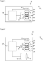
- FIG. 1 shows a block diagram of a camera as an example of an optoelectronic sensor 10 with receiving-side focus adjustment.
- Receiving light from a detection area 12 strikes a receiving optics 14, which leads the received light to a light receiver 16.
- the light receiver 16 is an image sensor having a plurality of light receiving elements in a row or matrix arrangement.
- Other sensors 10 use a photodiode, an APD (avalanche photodiode) or a SPAD receiver (single-photon avalanche diode).
- the receiving optics 14 is shown here purely by way of example with three lenses. Generally, it is any lens made of lenses and other optical elements such as apertures, prisms, and the like, and in the simplest case, a single lens.
- the receiving optics 14 is suspended movably. With the help of an actuator 18, such as a stepper motor or Tauchspulaktorik, the Empfangstopitk 14 is moved along its optical axis, on which the light receiver 16 is arranged, as shown by an arrow 20. These changes in distance between receiving optics 14 and light receiver 16 cause a refocusing.
- an actuator 18 such as a stepper motor or Tauchspulaktorik
- the suspension in the example shown comprises a movable support member 22 with the receiving optics 14, a two-part, fixed support member 24 and two rolled leaf springs 26 therebetween.
- the suspension and focus adjustment and variations thereof will be described later with reference to the FIGS. 3 to 7 explained in more detail.
- the illustrated position of the actuator 18 and the point of application of the arrow 20 is to be understood only functional and not geometric.
- the actuator 18 preferably acts on the circumference of the carrier element 22.
- the rolled leaf springs 26 in particular leave the area of the carrier element 22 freely accessible above and below the plane of the paper.
- a control and evaluation unit 28 is connected to the light receiver 16 and the actuator 18.
- a received signal of the light receiver 16 is read out by the control and evaluation unit 28 and stored, for example, as an image, processed or examined in a camera-based code reader on code areas, which are then decoded.
- About the actuators 18 each required focus position is set, which can also be realized with the aid of an additional, not shown distance sensor as autofocus.
- FIG. 2 shows a block diagram of another embodiment of an optoelectronic sensor 10.
- like reference numerals designate the same or corresponding features, which will not be described again.
- a transmission-side focus adjustment of a transmission optics 30 of a light emitter 32 is provided, for example with an LED or a laser as the light source.
- the receiving optics 14, however, is rigid.
- the position of the receiving optics 14 with the focus adjustment can be changed, the receiving optics 14 have a further focus adjustment or the receiving optics 14 are formed in a coaxial structure as common optics, which also acts as a transmitting optics 30.
- An example of an optoelectronic sensor 10 with the basic structure according to FIG. 2 is a barcode scanner.
- the light emitter 32 generates by means of the transmitting optics 30 a reading beam, which returns after reflection to an object, in particular code area in the detection area 12 and is guided via the receiving optics 14 to the light receiver 16.
- scanning is effected by means of a scanning mechanism (not shown), for example with a swinging or rotating mirror, which moves the reading beam over the code area.
- the task of the focus adjustment is to sufficiently focus the reading beam so that the code elements are resolved.
- the setting can be sufficient for a fixed or parameterized distance.
- the current distance is measured.
- an additional distance sensor whose reading beam itself can be used for a distance measurement, for example, impressed by amplitude modulation, a frequency on the read beam and the distance is determined in a phase method from the phase offset between the send and receive time.
- the received signal sent from the light receiver 16 to the control and evaluation unit 28 is modulated in its amplitude in the code bar in a corresponding manner.
- the evaluation unit 26 is therefore able to read the code information. It also recognizes when the received signal does not match any code. The finding of code areas and the reading of the code information is known per se and is therefore not explained in detail.
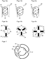
- Figure 3a-c show schematic sectional views of the suspension for the focus adjustment in different Auslenkungszuhormonn by different forces of the actuator 18, as shown by arrows denoted by "F".
- the optics 14, 30 on the movable support element 22 are omitted.
- the movable support member 22 is clamped on both sides by means of the two rolled leaf springs 26 between the fixed support member 24.
- the movable support member 22 acts as a vibrator, the fixed support member 24 as a stator.
- the rolled leaf springs 26 are fixed to the movable support member 22 and the holding member 24, each having a fixing point 34. The fixation is also conceivable at additional points, but this shortens the possible adjustment, or it can be omitted vice versa, since the rolled leaf springs 26 are clamped with their spring force and the rolling friction is less than the static friction.
- the rolled leaf springs 26 form a ring, which can be seen in cross-section. Due to the clamping between the carrier element 22 and retaining element 24, the ring is elongated, but deviates from an ellipse, since the lateral regions of the rolled leaf springs 26 to the respective contour of the contact surfaces 38 a-b with the support member 22 and the support member 24. Due to the cross-sectional view, the rolled leaf springs 26 can only be seen as a line. In fact, the ring in the direction perpendicular to the paper plane, according to the nature of a leaf spring, a flat extension. The corresponding lateral outer surfaces are pressed by the spring force against the contact surfaces 38a-b of carrier element 22 and holding element 24.
- the large contact surface 38a-b stabilizes the adjustment movements and the adjusted focus positions.
- the travel can be influenced by the length of the adjacent portion of the rolled leaf springs 26.
- the movement of the support member 22 is linear, in the drawing plane from top to bottom, corresponding to the optical axis of the optics 14, not shown, 30.
- the plane of the drawing is also the plane of the ring of the rolled leaf springs 26, in which consequently the movement remains.
- the direction of movement is parallel to a diameter of the ring, in particular the longest diameter, which arises due to pinching.
- the lateral guide is through the rolling Leaf springs 26 and their spring force guaranteed. With unequal rolled leaf springs 26 with different spring force of the linear motion is superimposed a certain rotation, the movement is then no longer strictly parallel to the longest diameter, but only tangential to two rolled leaf springs 26, but still considered in the context of the required travel paths as parallel can be.
- Figure 4a-b shows a schematic sectional view of the focus-adjustable receiving optics 14 based on the mechanical suspension just described for two different focal positions 40a-b.
- FIG. 4a is the movable support member 22 without force of the actuator 18 in an initial position with a first focus position 40a.
- the actuator 18 causes a force "F" down.
- the carrier element 22, including the receiving optics 14 moves along the optical axis 42 downwards.
- the shortened distance between receiving optics 14 and light receiver 16 causes a shift to the new focus position 40b.
- a refocusing in the transmission path works analogously, here only the light receiver 16 would have to be exchanged for the light transmitter 32.
- the geometries, masses and other optical and other parameters are set to the other task.
- the contact surfaces 38a-b with the rolled leaf springs 26 of the support member 22 and support member 24 are flat and parallel to each other.
- Figure 5a-c shows some examples of how design, so alternative special shape of the contact surfaces 38a-b can change the bias or rigidity of the suspension for the focus adjustment.
- the rigidity of material properties of the rolled leaf springs 26 and their geometry, so the bending radius depends.
- the basis of the FIGS. 5a-c explained design variants are not aimed at these global parameters, but locally different biases per focus position.
- the basic idea here is to change the distance between carrier element 22 and holding element 24 in relation to location. Characterized the rolled leaf spring 26 is more or less strongly clamped, there are different bending radii, and accordingly, the rolled leaf spring 26 is more or less resistant to rolling in the respective position
- FIGS. 5a-b show an example with a linear variation of the bias voltage.
- the distance between the carrier element 22 and the holding element 24 increases or decreases linearly from top to bottom along the optical axis.
- the contact surface 38b of the support member 22 is skewed, so that downward movements must overcome less and less bias.
- the contact surface 38a of the support member 24 is inclined, also such that now conversely, the distance is down towards shorter, so that the bias increases in movements of the support member 22 downward.
- both carrier element 22 and holding element 24 could have inclined contact surfaces 38a-b.
- FIG. 5c shows an example in which, instead of a linear variation by the inclined, but still flat, contact surfaces 38a-b in FIG Figure 5a-b a freeform surface is designed. This results in 22 different bias voltages or spring constants in different positions of the support member, which are largely freely selectable by the shape of the free-form surface in a wide range of variation.
- a freeform surface can be characterized by a sloping surface as in the FIGS. 5a-b out.
- a free-form surface offers the advantageous possibility of selectively introducing certain detent positions. These are focal positions in which the carrier element 22 remains stationary even without the action of force by the actuators 18, so that the actuators 18 each only have to act temporarily in order to change into a latching position. A locking position can therefore be kept without external force. This is in some ways already given by the static friction of the rolled leaf springs 26.
- a detent position is characterized in that in both adjustment directions a bias must be overcome to leave the detent position.
- the suspension comprises in each case two rolled leaf springs 26.
- This constellation is in FIG. 6a again shown in a simplified plan view showing only the movable support member 22, the fixed support member 24 and the two rolled leaf springs 26 therebetween.
- the arrangement diametrically opposite, as the alignment of the two leaf springs 26 to each other with an angle of 180 °, is particularly advantageous because there is then no resulting spring force, which acts laterally on the support member 22.
- the rolled leaf springs 26 could also compensate for a certain deviation, especially when two rolled leaf springs 26 with different properties are used.
- the Figures 6b and 6c show exemplary embodiments of a suspension with three rolled leaf springs 26 and four rolled leaf springs 26.
- the suspension is in each case symmetrical with a centrally mounted support member 22, which is advantageous, but not mandatory the case.
- the use of more than two rolled leaf springs 26 can improve the guiding properties and, among other things, the mechanical stability against external influences. Even more rolled leaf springs 26 are also possible.
- the previous suspensions provide for an at least substantially linear movement of the carrier element 22.
- a rotational component can be achieved by means of different rolled leaf springs 26.
- Another possibility also already mentioned is to arrange the carrier element 22 on at least one side on a further holding element without a rolled leaf spring 26 therebetween or even to fix it.
- FIG. 7 shows how with the concept of a mounted in rolled leaf springs 26 movable support member 22 a if necessary, purely rotational movement can be implemented quite specifically.
- the carrier element 22 has for this purpose an annular outer surface as a contact surface 38b, the retaining element 24 has a corresponding annular inner surface as a contact surface 38a.
- Several rolled leaf springs 26 are distributed over the circumference of the gap. A preferred arrangement provides for even distribution of three rolled leaf springs 26, but number and distribution may also be varied.
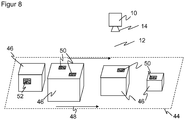
- FIG. 8 shows a possible application of the sensor 10 in mounting on a conveyor belt 44, which conveys objects 46, as indicated by the arrow 48, through the detection area 12 of the sensor 10.
- the objects 46 may carry code areas 50 on their outer surfaces.
- the task of the sensor 10 is to detect properties of the objects 46 and, in a preferred use as a code reader, to recognize the code regions 50, to read out the codes applied there, to decode them and to assign them to the respectively associated object 46.
- additional, not shown sensors 10 are preferably used from different perspectives.
Landscapes
- Physics & Mathematics (AREA)
- Engineering & Computer Science (AREA)
- General Physics & Mathematics (AREA)
- Electromagnetism (AREA)
- Optics & Photonics (AREA)
- Artificial Intelligence (AREA)
- Computer Vision & Pattern Recognition (AREA)
- General Health & Medical Sciences (AREA)
- Theoretical Computer Science (AREA)
- Toxicology (AREA)
- Health & Medical Sciences (AREA)
- Power Engineering (AREA)
- Computer Hardware Design (AREA)
- Condensed Matter Physics & Semiconductors (AREA)
- Microelectronics & Electronic Packaging (AREA)
- Quality & Reliability (AREA)
- Multimedia (AREA)
- Signal Processing (AREA)
- Lens Barrels (AREA)
- Automatic Focus Adjustment (AREA)
- Studio Devices (AREA)
- Focusing (AREA)
- Geophysics And Detection Of Objects (AREA)
Priority Applications (5)
| Application Number | Priority Date | Filing Date | Title |
|---|---|---|---|
| EP18155926.1A EP3525026A1 (fr) | 2018-02-09 | 2018-02-09 | Capteur optoélectronique et procédé de réglage de point focal |
| CN201811593380.9A CN110135214B (zh) | 2018-02-09 | 2018-12-25 | 光电传感器和用于焦点调节的方法 |
| KR1020190008077A KR102187151B1 (ko) | 2018-02-09 | 2019-01-22 | 광전자 센서 및 초점 조정 방법 |
| JP2019020705A JP6746736B2 (ja) | 2018-02-09 | 2019-02-07 | 光電センサ及び焦点調節方法 |
| US16/271,247 US11294139B2 (en) | 2018-02-09 | 2019-02-08 | Optoelectronic sensor and method of focus adjustment |
Applications Claiming Priority (1)
| Application Number | Priority Date | Filing Date | Title |
|---|---|---|---|
| EP18155926.1A EP3525026A1 (fr) | 2018-02-09 | 2018-02-09 | Capteur optoélectronique et procédé de réglage de point focal |
Publications (1)
| Publication Number | Publication Date |
|---|---|
| EP3525026A1 true EP3525026A1 (fr) | 2019-08-14 |
Family
ID=61192708
Family Applications (1)
| Application Number | Title | Priority Date | Filing Date |
|---|---|---|---|
| EP18155926.1A Ceased EP3525026A1 (fr) | 2018-02-09 | 2018-02-09 | Capteur optoélectronique et procédé de réglage de point focal |
Country Status (5)
| Country | Link |
|---|---|
| US (1) | US11294139B2 (fr) |
| EP (1) | EP3525026A1 (fr) |
| JP (1) | JP6746736B2 (fr) |
| KR (1) | KR102187151B1 (fr) |
| CN (1) | CN110135214B (fr) |
Cited By (2)
| Publication number | Priority date | Publication date | Assignee | Title |
|---|---|---|---|---|
| DE102019130963B3 (de) * | 2019-11-15 | 2020-09-17 | Sick Ag | Fokusmodul |
| EP4296771A1 (fr) | 2022-06-24 | 2023-12-27 | Sick Ag | Capteur optoélectronique et procédé de réglage du point focal |
Families Citing this family (1)
| Publication number | Priority date | Publication date | Assignee | Title |
|---|---|---|---|---|
| DE102020109928B3 (de) * | 2020-04-09 | 2020-12-31 | Sick Ag | Kamera und Verfahren zur Erfassung von Bilddaten |
Citations (8)
| Publication number | Priority date | Publication date | Assignee | Title |
|---|---|---|---|---|
| US5257279A (en) * | 1992-06-04 | 1993-10-26 | Spectra-Physics Laserplane, Inc. | Adjustable focus technique and apparatus using a moveable weak lens |
| EP0757270A1 (fr) | 1995-08-03 | 1997-02-05 | Scantech B.V. | Dispositif à mise au point automatique |
| EP1895343A1 (fr) * | 2006-08-31 | 2008-03-05 | Mitsumi Electric Co., Ltd. | Module d'appareil photographique |
| US20090208197A1 (en) * | 2008-02-14 | 2009-08-20 | Hoya Corporation | Retracting mechanism of a lens barrel |
| US20100067130A1 (en) * | 2008-09-17 | 2010-03-18 | Sony Corporation | Lens module and electronic apparatus |
| EP2498113A1 (fr) | 2011-03-10 | 2012-09-12 | Sick AG | Dispositif de réglage d'objectif pour un lecteur de code |
| US20160178923A1 (en) | 2013-08-09 | 2016-06-23 | Mitsumi Electric Co., Ltd. | Lens holder drive device, camera module, and portable terminal provided with camera |
| DE102016112123A1 (de) | 2016-07-01 | 2018-01-04 | Sick Ag | Optischer Codeleser |
Family Cites Families (6)
| Publication number | Priority date | Publication date | Assignee | Title |
|---|---|---|---|---|
| US4184927A (en) * | 1976-12-30 | 1980-01-22 | Riken Keikinzoku Kogyo Kabushiki Kaisha | Process and apparatus for effecting surface treatment of workpieces |
| JPS61151848A (ja) * | 1984-12-25 | 1986-07-10 | Nec Home Electronics Ltd | 3軸光ヘツド |
| KR100582746B1 (ko) * | 2003-12-19 | 2006-05-23 | 주식회사 하이소닉 | 영상 촬영 장치 |
| JP4384077B2 (ja) * | 2005-04-22 | 2009-12-16 | 株式会社日立メディアエレクトロニクス | 光ピックアップ |
| JP5623196B2 (ja) * | 2009-11-20 | 2014-11-12 | キヤノン株式会社 | レンズ鏡筒及びそれを有する光学機器 |
| TW201430482A (zh) * | 2013-01-31 | 2014-08-01 | Hon Hai Prec Ind Co Ltd | 相機模組測試裝置及相機模組測試用鏡片 |
-
2018
- 2018-02-09 EP EP18155926.1A patent/EP3525026A1/fr not_active Ceased
- 2018-12-25 CN CN201811593380.9A patent/CN110135214B/zh active Active
-
2019
- 2019-01-22 KR KR1020190008077A patent/KR102187151B1/ko active IP Right Grant
- 2019-02-07 JP JP2019020705A patent/JP6746736B2/ja active Active
- 2019-02-08 US US16/271,247 patent/US11294139B2/en active Active
Patent Citations (8)
| Publication number | Priority date | Publication date | Assignee | Title |
|---|---|---|---|---|
| US5257279A (en) * | 1992-06-04 | 1993-10-26 | Spectra-Physics Laserplane, Inc. | Adjustable focus technique and apparatus using a moveable weak lens |
| EP0757270A1 (fr) | 1995-08-03 | 1997-02-05 | Scantech B.V. | Dispositif à mise au point automatique |
| EP1895343A1 (fr) * | 2006-08-31 | 2008-03-05 | Mitsumi Electric Co., Ltd. | Module d'appareil photographique |
| US20090208197A1 (en) * | 2008-02-14 | 2009-08-20 | Hoya Corporation | Retracting mechanism of a lens barrel |
| US20100067130A1 (en) * | 2008-09-17 | 2010-03-18 | Sony Corporation | Lens module and electronic apparatus |
| EP2498113A1 (fr) | 2011-03-10 | 2012-09-12 | Sick AG | Dispositif de réglage d'objectif pour un lecteur de code |
| US20160178923A1 (en) | 2013-08-09 | 2016-06-23 | Mitsumi Electric Co., Ltd. | Lens holder drive device, camera module, and portable terminal provided with camera |
| DE102016112123A1 (de) | 2016-07-01 | 2018-01-04 | Sick Ag | Optischer Codeleser |
Cited By (3)
| Publication number | Priority date | Publication date | Assignee | Title |
|---|---|---|---|---|
| DE102019130963B3 (de) * | 2019-11-15 | 2020-09-17 | Sick Ag | Fokusmodul |
| US11582380B2 (en) | 2019-11-15 | 2023-02-14 | Sick Ag | Focus module |
| EP4296771A1 (fr) | 2022-06-24 | 2023-12-27 | Sick Ag | Capteur optoélectronique et procédé de réglage du point focal |
Also Published As
| Publication number | Publication date |
|---|---|
| US20190250364A1 (en) | 2019-08-15 |
| CN110135214B (zh) | 2022-11-29 |
| KR20190096803A (ko) | 2019-08-20 |
| JP2019179236A (ja) | 2019-10-17 |
| CN110135214A (zh) | 2019-08-16 |
| JP6746736B2 (ja) | 2020-08-26 |
| KR102187151B1 (ko) | 2020-12-04 |
| US11294139B2 (en) | 2022-04-05 |
Similar Documents
| Publication | Publication Date | Title |
|---|---|---|
| EP2546776B1 (fr) | Lecteur de code basé sur un appareil de prise de vue et son procédé de fabrication ajustée | |
| EP2924477B1 (fr) | Dispositif optoélectronique et procédé de détection d'informations d'objets | |
| EP2937810B1 (fr) | Système de caméra et procédé de détermination d'un flux mobile d'objets | |
| DE102016112123B4 (de) | Optischer Codeleser und Verfahren zum Lesen von optischen Codes | |
| EP3525026A1 (fr) | Capteur optoélectronique et procédé de réglage de point focal | |
| EP2924973B1 (fr) | Dispositif optoélectronique et son procédé de réglage | |
| DE102019130963B3 (de) | Fokusmodul | |
| EP2498113A1 (fr) | Dispositif de réglage d'objectif pour un lecteur de code | |
| EP3892955B1 (fr) | Caméra et procédé de détection des données d'image | |
| EP3893051B1 (fr) | Acquisition de données d'image d'un objet mobile | |
| EP2112540A1 (fr) | Dispositif d'identification pour l'acquisition linéaire d'un code dans un plan d'objet | |
| EP3540490A2 (fr) | Capteur optoélectronique et procédé de réglage de la mise au point d'une optique | |
| EP2860553A1 (fr) | Capteur optoélectronique et procédé destiné à la saisie d'informations d'objet | |
| EP3910547B1 (fr) | Détection des objets mobiles | |
| EP1130533B1 (fr) | Scanner | |
| EP3617766A1 (fr) | Optique à réglage de foyer | |
| EP3693927B1 (fr) | Alignement d'une caméra à balayage linéaire avec des triangles comme cibles d'alignement. | |
| DE202009017346U1 (de) | Optikvorrichtung für einen optoelektronischen Sensor | |
| DE202019106399U1 (de) | Fokusmodul | |
| EP4047507B1 (fr) | Détection d'un code optique | |
| EP4296771B1 (fr) | Capteur optoélectronique et procédé de réglage du point focal | |
| DE202018104900U1 (de) | Fokusverstellbare Optik | |
| DE102012002853B4 (de) | Fokussiervorrichtung mit einem ein nichtlineares Getriebe aufweisenden Phasenplattensystem | |
| EP1148352A2 (fr) | Capteur optique | |
| DE202018106048U1 (de) | Barcodescanner |
Legal Events
| Date | Code | Title | Description |
|---|---|---|---|
| PUAI | Public reference made under article 153(3) epc to a published international application that has entered the european phase |
Free format text: ORIGINAL CODE: 0009012 |
|
| STAA | Information on the status of an ep patent application or granted ep patent |
Free format text: STATUS: REQUEST FOR EXAMINATION WAS MADE |
|
| 17P | Request for examination filed |
Effective date: 20190709 |
|
| AK | Designated contracting states |
Kind code of ref document: A1 Designated state(s): AL AT BE BG CH CY CZ DE DK EE ES FI FR GB GR HR HU IE IS IT LI LT LU LV MC MK MT NL NO PL PT RO RS SE SI SK SM TR |
|
| AX | Request for extension of the european patent |
Extension state: BA ME |
|
| RAP1 | Party data changed (applicant data changed or rights of an application transferred) |
Owner name: SICK AG |
|
| STAA | Information on the status of an ep patent application or granted ep patent |
Free format text: STATUS: EXAMINATION IS IN PROGRESS |
|
| 17Q | First examination report despatched |
Effective date: 20200403 |
|
| STAA | Information on the status of an ep patent application or granted ep patent |
Free format text: STATUS: EXAMINATION IS IN PROGRESS |
|
| STAA | Information on the status of an ep patent application or granted ep patent |
Free format text: STATUS: THE APPLICATION HAS BEEN REFUSED |
|
| 18R | Application refused |
Effective date: 20210123 |