EP3524936B1 - Verfahren und vorrichtung zur bereitstellung von informationen für ein fahrendes fahrzeug - Google Patents
Verfahren und vorrichtung zur bereitstellung von informationen für ein fahrendes fahrzeug Download PDFInfo
- Publication number
- EP3524936B1 EP3524936B1 EP18203797.8A EP18203797A EP3524936B1 EP 3524936 B1 EP3524936 B1 EP 3524936B1 EP 18203797 A EP18203797 A EP 18203797A EP 3524936 B1 EP3524936 B1 EP 3524936B1
- Authority
- EP
- European Patent Office
- Prior art keywords
- vehicle
- information
- line
- driving
- image
- Prior art date
- Legal status (The legal status is an assumption and is not a legal conclusion. Google has not performed a legal analysis and makes no representation as to the accuracy of the status listed.)
- Active
Links
Images







Classifications
-
- G—PHYSICS
- G01—MEASURING; TESTING
- G01C—MEASURING DISTANCES, LEVELS OR BEARINGS; SURVEYING; NAVIGATION; GYROSCOPIC INSTRUMENTS; PHOTOGRAMMETRY OR VIDEOGRAMMETRY
- G01C21/00—Navigation; Navigational instruments not provided for in groups G01C1/00 - G01C19/00
- G01C21/26—Navigation; Navigational instruments not provided for in groups G01C1/00 - G01C19/00 specially adapted for navigation in a road network
- G01C21/34—Route searching; Route guidance
- G01C21/36—Input/output arrangements for on-board computers
- G01C21/3602—Input other than that of destination using image analysis, e.g. detection of road signs, lanes, buildings, real preceding vehicles using a camera
-
- B—PERFORMING OPERATIONS; TRANSPORTING
- B60—VEHICLES IN GENERAL
- B60W—CONJOINT CONTROL OF VEHICLE SUB-UNITS OF DIFFERENT TYPE OR DIFFERENT FUNCTION; CONTROL SYSTEMS SPECIALLY ADAPTED FOR HYBRID VEHICLES; ROAD VEHICLE DRIVE CONTROL SYSTEMS FOR PURPOSES NOT RELATED TO THE CONTROL OF A PARTICULAR SUB-UNIT
- B60W50/00—Details of control systems for road vehicle drive control not related to the control of a particular sub-unit, e.g. process diagnostic or vehicle driver interfaces
- B60W50/08—Interaction between the driver and the control system
- B60W50/14—Means for informing the driver, warning the driver or prompting a driver intervention
-
- B—PERFORMING OPERATIONS; TRANSPORTING
- B60—VEHICLES IN GENERAL
- B60W—CONJOINT CONTROL OF VEHICLE SUB-UNITS OF DIFFERENT TYPE OR DIFFERENT FUNCTION; CONTROL SYSTEMS SPECIALLY ADAPTED FOR HYBRID VEHICLES; ROAD VEHICLE DRIVE CONTROL SYSTEMS FOR PURPOSES NOT RELATED TO THE CONTROL OF A PARTICULAR SUB-UNIT
- B60W30/00—Purposes of road vehicle drive control systems not related to the control of a particular sub-unit, e.g. of systems using conjoint control of vehicle sub-units
- B60W30/18—Propelling the vehicle
-
- B—PERFORMING OPERATIONS; TRANSPORTING
- B60—VEHICLES IN GENERAL
- B60W—CONJOINT CONTROL OF VEHICLE SUB-UNITS OF DIFFERENT TYPE OR DIFFERENT FUNCTION; CONTROL SYSTEMS SPECIALLY ADAPTED FOR HYBRID VEHICLES; ROAD VEHICLE DRIVE CONTROL SYSTEMS FOR PURPOSES NOT RELATED TO THE CONTROL OF A PARTICULAR SUB-UNIT
- B60W40/00—Estimation or calculation of non-directly measurable driving parameters for road vehicle drive control systems not related to the control of a particular sub unit, e.g. by using mathematical models
- B60W40/02—Estimation or calculation of non-directly measurable driving parameters for road vehicle drive control systems not related to the control of a particular sub unit, e.g. by using mathematical models related to ambient conditions
- B60W40/06—Road conditions
-
- B—PERFORMING OPERATIONS; TRANSPORTING
- B60—VEHICLES IN GENERAL
- B60W—CONJOINT CONTROL OF VEHICLE SUB-UNITS OF DIFFERENT TYPE OR DIFFERENT FUNCTION; CONTROL SYSTEMS SPECIALLY ADAPTED FOR HYBRID VEHICLES; ROAD VEHICLE DRIVE CONTROL SYSTEMS FOR PURPOSES NOT RELATED TO THE CONTROL OF A PARTICULAR SUB-UNIT
- B60W40/00—Estimation or calculation of non-directly measurable driving parameters for road vehicle drive control systems not related to the control of a particular sub unit, e.g. by using mathematical models
- B60W40/02—Estimation or calculation of non-directly measurable driving parameters for road vehicle drive control systems not related to the control of a particular sub unit, e.g. by using mathematical models related to ambient conditions
- B60W40/06—Road conditions
- B60W40/072—Curvature of the road
-
- G—PHYSICS
- G01—MEASURING; TESTING
- G01C—MEASURING DISTANCES, LEVELS OR BEARINGS; SURVEYING; NAVIGATION; GYROSCOPIC INSTRUMENTS; PHOTOGRAMMETRY OR VIDEOGRAMMETRY
- G01C21/00—Navigation; Navigational instruments not provided for in groups G01C1/00 - G01C19/00
- G01C21/26—Navigation; Navigational instruments not provided for in groups G01C1/00 - G01C19/00 specially adapted for navigation in a road network
- G01C21/34—Route searching; Route guidance
- G01C21/36—Input/output arrangements for on-board computers
- G01C21/3626—Details of the output of route guidance instructions
- G01C21/3658—Lane guidance
-
- G—PHYSICS
- G05—CONTROLLING; REGULATING
- G05D—SYSTEMS FOR CONTROLLING OR REGULATING NON-ELECTRIC VARIABLES
- G05D1/00—Control of position, course, altitude or attitude of land, water, air or space vehicles, e.g. using automatic pilots
- G05D1/02—Control of position or course in two dimensions
- G05D1/021—Control of position or course in two dimensions specially adapted to land vehicles
- G05D1/0231—Control of position or course in two dimensions specially adapted to land vehicles using optical position detecting means
-
- G—PHYSICS
- G06—COMPUTING OR CALCULATING; COUNTING
- G06F—ELECTRIC DIGITAL DATA PROCESSING
- G06F18/00—Pattern recognition
- G06F18/20—Analysing
- G06F18/24—Classification techniques
-
- G—PHYSICS
- G06—COMPUTING OR CALCULATING; COUNTING
- G06T—IMAGE DATA PROCESSING OR GENERATION, IN GENERAL
- G06T7/00—Image analysis
- G06T7/10—Segmentation; Edge detection
- G06T7/11—Region-based segmentation
-
- G—PHYSICS
- G06—COMPUTING OR CALCULATING; COUNTING
- G06T—IMAGE DATA PROCESSING OR GENERATION, IN GENERAL
- G06T7/00—Image analysis
- G06T7/50—Depth or shape recovery
-
- G—PHYSICS
- G06—COMPUTING OR CALCULATING; COUNTING
- G06T—IMAGE DATA PROCESSING OR GENERATION, IN GENERAL
- G06T7/00—Image analysis
- G06T7/70—Determining position or orientation of objects or cameras
- G06T7/73—Determining position or orientation of objects or cameras using feature-based methods
-
- G—PHYSICS
- G06—COMPUTING OR CALCULATING; COUNTING
- G06V—IMAGE OR VIDEO RECOGNITION OR UNDERSTANDING
- G06V20/00—Scenes; Scene-specific elements
- G06V20/50—Context or environment of the image
- G06V20/56—Context or environment of the image exterior to a vehicle by using sensors mounted on the vehicle
- G06V20/588—Recognition of the road, e.g. of lane markings; Recognition of the vehicle driving pattern in relation to the road
-
- G—PHYSICS
- G08—SIGNALLING
- G08G—TRAFFIC CONTROL SYSTEMS
- G08G1/00—Traffic control systems for road vehicles
- G08G1/16—Anti-collision systems
- G08G1/167—Driving aids for lane monitoring, lane changing, e.g. blind spot detection
-
- B—PERFORMING OPERATIONS; TRANSPORTING
- B60—VEHICLES IN GENERAL
- B60W—CONJOINT CONTROL OF VEHICLE SUB-UNITS OF DIFFERENT TYPE OR DIFFERENT FUNCTION; CONTROL SYSTEMS SPECIALLY ADAPTED FOR HYBRID VEHICLES; ROAD VEHICLE DRIVE CONTROL SYSTEMS FOR PURPOSES NOT RELATED TO THE CONTROL OF A PARTICULAR SUB-UNIT
- B60W2420/00—Indexing codes relating to the type of sensors based on the principle of their operation
- B60W2420/40—Photo, light or radio wave sensitive means, e.g. infrared sensors
- B60W2420/403—Image sensing, e.g. optical camera
-
- B—PERFORMING OPERATIONS; TRANSPORTING
- B60—VEHICLES IN GENERAL
- B60W—CONJOINT CONTROL OF VEHICLE SUB-UNITS OF DIFFERENT TYPE OR DIFFERENT FUNCTION; CONTROL SYSTEMS SPECIALLY ADAPTED FOR HYBRID VEHICLES; ROAD VEHICLE DRIVE CONTROL SYSTEMS FOR PURPOSES NOT RELATED TO THE CONTROL OF A PARTICULAR SUB-UNIT
- B60W2520/00—Input parameters relating to overall vehicle dynamics
- B60W2520/10—Longitudinal speed
-
- B—PERFORMING OPERATIONS; TRANSPORTING
- B60—VEHICLES IN GENERAL
- B60W—CONJOINT CONTROL OF VEHICLE SUB-UNITS OF DIFFERENT TYPE OR DIFFERENT FUNCTION; CONTROL SYSTEMS SPECIALLY ADAPTED FOR HYBRID VEHICLES; ROAD VEHICLE DRIVE CONTROL SYSTEMS FOR PURPOSES NOT RELATED TO THE CONTROL OF A PARTICULAR SUB-UNIT
- B60W2554/00—Input parameters relating to objects
- B60W2554/80—Spatial relation or speed relative to objects
- B60W2554/801—Lateral distance
-
- B—PERFORMING OPERATIONS; TRANSPORTING
- B60—VEHICLES IN GENERAL
- B60W—CONJOINT CONTROL OF VEHICLE SUB-UNITS OF DIFFERENT TYPE OR DIFFERENT FUNCTION; CONTROL SYSTEMS SPECIALLY ADAPTED FOR HYBRID VEHICLES; ROAD VEHICLE DRIVE CONTROL SYSTEMS FOR PURPOSES NOT RELATED TO THE CONTROL OF A PARTICULAR SUB-UNIT
- B60W2555/00—Input parameters relating to exterior conditions, not covered by groups B60W2552/00, B60W2554/00
- B60W2555/20—Ambient conditions, e.g. wind or rain
-
- G—PHYSICS
- G06—COMPUTING OR CALCULATING; COUNTING
- G06T—IMAGE DATA PROCESSING OR GENERATION, IN GENERAL
- G06T2207/00—Indexing scheme for image analysis or image enhancement
- G06T2207/30—Subject of image; Context of image processing
- G06T2207/30241—Trajectory
-
- G—PHYSICS
- G06—COMPUTING OR CALCULATING; COUNTING
- G06T—IMAGE DATA PROCESSING OR GENERATION, IN GENERAL
- G06T2207/00—Indexing scheme for image analysis or image enhancement
- G06T2207/30—Subject of image; Context of image processing
- G06T2207/30244—Camera pose
-
- G—PHYSICS
- G06—COMPUTING OR CALCULATING; COUNTING
- G06T—IMAGE DATA PROCESSING OR GENERATION, IN GENERAL
- G06T2207/00—Indexing scheme for image analysis or image enhancement
- G06T2207/30—Subject of image; Context of image processing
- G06T2207/30248—Vehicle exterior or interior
- G06T2207/30252—Vehicle exterior; Vicinity of vehicle
- G06T2207/30256—Lane; Road marking
Definitions
- This application relates to a method and apparatus providing information for driving of a vehicle.
- Visual information augmentation technologies are provided to assist the steering of a vehicle and other transportation means.
- various methods may be used to extract a lane marking or road information from a driving image.
- a method of providing information for driving a vehicle is provided in claim 1.
- the detecting of the lane region may include classifying an object included in the driving image, generating a segmentation image in which the object included in the driving image is classified, and detecting the lane region from the generated segmentation image.
- the determining of the curvature information may include determining a current location of the vehicle, and determining the curvature information based on a plurality of waypoints corresponding to the current location of the vehicle on a map.
- the determining of the curvature information based on the waypoints may include selecting the waypoints within a look-ahead distance from the current location.
- the determining of the curvature information based on the waypoints may include recognizing a shape of the road on the map based on the waypoints, and determining the curvature information based on the shape of the road on the map.
- the recognizing of the shape of the road on the map may include obtaining a regression function expressing the shape of the road on the map with a linear regression analysis on the waypoints.
- the look-ahead distance may be determined based on any one or any combination of a speed of the vehicle, a visible distance, a weather condition, a driving condition, and a condition of the road.
- the determining of the curvature information may include selecting, when the road on which the vehicle is driving includes a plurality of lanes, one of the lanes based on destination information of the vehicle; and determining curvature information of a road corresponding to the selected lane.
- the estimating of the lateral offset of the vehicle may include converting an image of the lane region into a top-view image, calculating polynomial fitting scores of lines included in the top-view image with respect to the reference line, and estimating a lateral offset of the vehicle based on the polynomial fitting scores.
- the calculating of the polynomial fitting scores may include calculating, while moving the reference line by a predetermined number of pixel units, candidate fitting scores in response to the reference line being moved, by counting a number of matching pixels between the lines included in the top-view image and the reference line.
- the calculating of the candidate fitting scores may include moving the reference line by the predetermined number of pixel units, counting a number of matching pixels between the lines included in the top-view image and the reference line moved by the predetermined number of pixel units, and calculating a candidate fitting score associated with the moved reference line based on the number of matching pixels.
- the estimating of the lateral offset of the vehicle may include detecting lines based on the polynomial fitting scores, and calculating the lateral offset based on the detected lines and a lateral position of the vehicle in the top-view image.
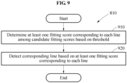
- the detecting of the lines may include determining at least one polynomial fitting score corresponding to each line among the fitting scores based on a threshold, and detecting a corresponding line based on the at least one polynomial fitting score corresponding to each line.
- the detecting of the corresponding line may include detecting a polynomial fitting score having a highest value from at least one polynomial fitting score of the corresponding line, and determining the corresponding line based on offset information corresponding to the detected polynomial fitting score.
- the detecting of the corresponding line may include obtaining a weighted sum of at least one item of offset information corresponding to the at least one polynomial fitting score based on at least one polynomial fitting score of the corresponding line as a weight, and determining the corresponding line based on the weighted sum.
- the calculating of the lateral offset may include determining a center line between left and right lines adjacent to the lateral position of the vehicle, and calculating a distance between the center line and the lateral position of the vehicle.
- the lateral position of the vehicle in the top-view image may include a laterally central position of the top-view image.
- the lateral position of the vehicle in the top-view image may be determined based on a lateral position of a camera attached to the vehicle to capture the driving image.
- the outputting of the signal including the information for the driving the vehicle may include determining a local lane of the vehicle based on the curvature information and the lateral offset, and generating a signal for controlling the driving of the vehicle based on the local lane.
- the outputting of the signal including the information for the driving of the vehicle may include determining a local lane of the vehicle based on the curvature information and the lateral offset, and providing driving information including a driving lane of the vehicle based on the local lane.
- the method may include acquiring the driving image, and acquiring the map information.
- an apparatus is provided in claim 12.
- first,” “second,” and “third” may be used herein to describe various members, components, regions, layers, or sections, these members, components, regions, layers, or sections are not to be limited by these terms. Rather, these terms are only used to distinguish one member, component, region, layer, or section from another member, component, region, layer, or section. Thus, a first member, component, region, layer, or section referred to in examples described herein may also be referred to as a second member, component, region, layer, or section without departing from the teachings of the examples.
- spatially relative terms such as “above,” “upper,” “below,” and “lower” may be used herein for ease of description to describe one element's relationship to another element as shown in the figures. Such spatially relative terms are intended to encompass different orientations of the device in use or operation in addition to the orientation depicted in the figures. For example, if the device in the figures is turned over, an element described as being “above” or “upper” relative to another element will then be “below” or “lower” relative to the other element. Thus, the term “above” encompasses both the above and below orientations depending on the spatial orientation of the device.
- the device may also be oriented in other ways (for example, rotated 90 degrees or at other orientations), and the spatially relative terms used herein are to be interpreted accordingly.
- Examples set forth hereinafter may be used to display a virtual route or generate visual information to assist in the steering or driving of, or by, an autonomous vehicle of, or in, an augmented reality (AR) navigation system of a smart vehicle.
- the examples may be used to interpret visual information and assist in the safe and pleasant driving by or in a device including an intelligent system such as a head-up display (HUD) installed for driving assistance or fully autonomous driving of a vehicle.
- HUD head-up display
- the examples may be or be applied to, for example, an autonomous vehicle, an intelligent vehicle, a smart phone, and a mobile device, but is not limited thereto.
- FIG. 1 illustrates an example of a method of providing information for driving of a vehicle.
- a polynomial equation including an offset from a center of a road and a curvature of the road may be selected and used to generate a local path to maintain a position in a lane, or to perform a lane change.
- the vehicle or other apparatus providing information for driving of the vehicle (hereinafter, also commonly referred to as "information providing apparatus") may extract curvature information of a road from map information.
- the information providing apparatus may use the curvature information of the road when detecting a lateral offset based on lines or lane markings from a driving image.
- FIG. 1A illustrates a plurality of waypoints 130, ... , 140 corresponding to a current location of a vehicle 110 on a map.
- the plurality of waypoints 130, ... , 140 corresponds to points of a road 150 on the map.
- the road 150 corresponds to a road on which the vehicle 110 is driving.
- the information providing apparatus determines curvature information of the road 150 on which the vehicle 110 is driving based on the plurality of waypoints 130, ... , 140 within a look-ahead distance between the waypoint 130 adjacent to a current location of the vehicle and a waypoint 140 on the map.
- the waypoint 140 may be located a defined or provided distance from the waypoint 130 in a position ahead of the vehicle 110.
- the term "look-ahead distance" may refer to a distance to be used to generate information for driving the vehicle 110, and is determined based on, for example, any one or any combination of a speed of the vehicle 110, a defined or provided visible distance, weather conditions, driving conditions, road conditions, and a destination of the vehicle 110. Additionally, the look-ahead distance may correspond to a distance that appropriately represents the plurality of waypoints 130, ... , 140 based on a degree of a line regression function, for example, a polynomial equation.
- the information providing apparatus generates or obtains a regression function expressing a shape of the road 150 on the map through a linear regression analysis on the plurality of waypoints 130, ... , 140.
- the information providing apparatus may determine the curvature information of the road 150 using the regression function.
- vehicle refers to a vehicle driving on a road and includes, for example, an autonomous or automated driving vehicle, and an intelligent or smart vehicle equipped with an advanced driver assistance system (ADAS).
- ADAS advanced driver assistance system
- road refers to a surface on which vehicles drive, and includes various types of roads such as, for example, a highway, a national road, a rural road, a local road, an expressway, and a motorway.
- the road includes one or more lanes.
- lane refers to a specific designated space or region on the road that is distinguished, e.g., by lines marked on a surface of the road. A single lane is distinguished by left and right lines thereof.
- the “lines” are various types of indicators or lines, for example, solid lines, broken lines, curved lines, and zigzag lines marked in colors such as white, blue or yellow on the surface of the road.
- the term "lane region” includes a region including lines or a region corresponding to the lines in a driving image.
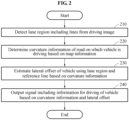
- FIG. 2 illustrates an example of a method of providing information for driving of a vehicle.
- the operations in FIG. 2 may be performed in the sequence and manner as shown, although the order of some operations may be changed or some of the operations omitted without departing from the scope of the illustrative examples described. Many of the operations shown in FIG. 2 may be performed in parallel or concurrently.
- One or more blocks of FIG. 2 , and combinations of the blocks, can be implemented by special purpose hardware-based computer that perform the specified functions, or combinations of special purpose hardware and computer instructions.
- FIG. 2 will be described below with respect to an information providing apparatus, such as corresponding to the information providing apparatus of any of FIGS. 1A and 1B .
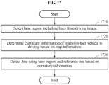
- an information providing apparatus detects a lane region of a road including lines from a driving image.
- the information providing apparatus acquires the driving image using, for example, an included image capture device mounted on the vehicle.
- the vehicle may correspond to the vehicle 110 of FIG. 1 .
- the driving image includes a single driving image or a plurality of driving images.
- the image capture device may be attached at a predetermined position, for example, a windshield, a dashboard, and a rear-view mirror of the vehicle to capture a driving image of a front scene from the vehicle.
- the location of the image capture device is not limited thereto.
- the image capture device includes, for example, a vision sensor, an image sensor, or a device that performs a similar function.
- the image capture device may capture a single image or may capture an image for each of multiple frames.
- the driving image is captured by an image capture device included in the information providing apparatus or a device other than the information providing apparatus.
- the driving image may be, for example, a driving image 1310 of FIG. 13A .
- the information providing apparatus detects the lane region by classifying pixels corresponding to line components or road components in the driving image based on a deep learning scheme of a neural network or through other machine learning models. A method of detecting a lane region using the information providing apparatus will be further described with reference to FIG. 3 .
- the information providing apparatus determines curvature information of a road on which the vehicle is driving based on map information.
- the map information includes, for example, a map representing geographic features on the earth using symbols, characters, and images, map coordinates including latitudes, longitudes, and altitudes of the geographic features, and a plurality of waypoints on a path represented on the map.
- the plurality of waypoints may be a set of coordinates obtained at preset intervals when the vehicle drives in a single lane on a road.
- the map information corresponds to map information at a level of a general map or map information at a level of a general navigation.
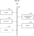
- the map information may be stored in a memory (for example, a memory 1940 of FIG. 19 ) of the information providing apparatus, or may be received from an external source of the information providing apparatus through a communication interface (for example, a communication interface 1920 of FIG. 19 ) of the information providing apparatus.
- the information providing apparatus selects a plurality of waypoints within a look-ahead distance from a current location of the vehicle on the map and obtains a regression function expressing a shape of the road on the map through a linear regression analysis on the waypoints.
- the current location of the vehicle is measured using, for example, a GPS sensor, an accelerometer sensor, and a compass sensor included in the information providing apparatus.
- the information providing apparatus determines curvature information of the road using the regression function. A method of determining curvature information of a road using the information providing apparatus will be further described with reference to FIGS. 4 and 5 .
- the information providing apparatus estimates a lateral offset of the vehicle using the lane region and a reference line that is formed from the curvature information.
- the reference line may be in a straight-line shape.
- the reference line may be in a curve shape.
- the curve shape includes, for example, a curve shape having a curvature in one direction, a curve shape having curvatures in at least two directions, a curve shape corresponding to at least a portion of a circle, and a curve shape corresponding to at least a portion of an ellipse.
- the lateral offset of the vehicle corresponds to a distance between a center of the vehicle and a center of a lane in which the vehicle is driving. To generate a local path to maintain a position in a lane, the lateral offset of the vehicle may be accurately determined. A method of estimating a lateral offset of a vehicle using the information providing apparatus will be further described with reference to FIGS. 6 through 9 .
- the information providing apparatus outputs a signal including information for driving of the vehicle based on the curvature information and the lateral offset.
- the information providing apparatus may determine a local path of the vehicle based on the curvature information and the lateral offset.
- the information providing apparatus may generate the information for the driving of the vehicle based on the local path.
- the information for the driving of the vehicle includes, for example, wheel steering control information, acceleration and deceleration control information associated with an accelerator and a brake of the vehicle, driving information of a detected lane, image information including a local path of a vehicle, and acoustic information that represents control information and image information represented by various sounds.
- the information for the driving of the vehicle is determined based on a line regression function to which the curvature information and the lateral offset are applied.
- the line regression function is in a form of, for example, a polynomial equation such as c 2 x 2 + c 1 x + c 0 , or a clothoid that is a type of a plane curve.
- the clothoid is a spiral whose change in curvature is inversely proportional to a length of a curve, and corresponds to a curve matching a driving trajectory of the vehicle when a steering wheel of the vehicle is rotated at a constant angular velocity.
- the information providing apparatus provides driving information including a driving path image or driving path information of a vehicle based on a local path so as to be displayed in a display device such as an HUD.
- FIG. 3 illustrates an example of a method of detecting a lane region.
- the operations in FIG. 3 may be performed in the sequence and manner as shown, although the order of some operations may be changed or some of the operations omitted without departing from the scope of the illustrative examples described. Many of the operations shown in FIG. 3 may be performed in parallel or concurrently.
- One or more blocks of FIG. 3 , and combinations of the blocks, can be implemented by special purpose hardware-based computer that perform the specified functions, or combinations of special purpose hardware and computer instructions.
- FIG. 3 will be described below with respect to an information providing apparatus, such as corresponding to the information providing apparatus of any of FIGS. 1A and 1B .
- an information providing apparatus generates a segmentation image in which an object included in a driving image is classified.
- the information providing apparatus generates the segmentation image by segmenting the driving image into objects included in the driving image by a semantic unit and determining the semantics of an object (a line or a road) for each segmented region by a pixel unit.
- the objects are classified by a class unit.
- a class used herein may include various semantic units, for example, a road, a vehicle, a sidewalk, a human being, an animal, sky, and a building.
- the segmentation image is, for example, a segmentation image 1330 of FIG. 13B . A method of generating a segmentation image using the information providing apparatus will be further described with reference to FIG. 13B .
- the information providing apparatus detects a lane region from the segmentation image.
- the information providing apparatus precisely identifies where and how an element or a component of an image, for example, an object and a background, is present from a pixel-unit label included in the segmentation image.
- the information providing apparatus generates an image of a lane region including pixels classified as a line class.
- the image of the lane region detected from the segmentation image is, for example, an image 1410 of FIG. 14A .
- the information providing apparatus detects the lane region from the driving image using, for example, a support vector machine (SVM), a deep neural network (DNN) and a CNN trained to recognize a lane region including lines.
- SVM support vector machine
- DNN deep neural network
- the CNN used herein may be trained in advance to determine a bounding box of a line to be detected from a driving image along with a type of the line to be detected.
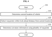
- FIG. 4 illustrates an example of a method of determining curvature information.
- the operations in FIG. 4 may be performed in the sequence and manner as shown, although the order of some operations may be changed or some of the operations omitted without departing from the scope of the illustrative examples described. Many of the operations shown in FIG. 4 may be performed in parallel or concurrently.
- One or more blocks of FIG. 4 , and combinations of the blocks, can be implemented by special purpose hardware-based computer that perform the specified functions, or combinations of special purpose hardware and computer instructions.
- FIG. 4 will be described below with respect to an information providing apparatus, such as corresponding to the information providing apparatus of any of FIGS. 1A and 1B .
- an information providing apparatus determines a current location of a vehicle.
- the information providing apparatus determines the current location of the vehicle based on, for example, global positioning system (GPS) information and map information.
- GPS global positioning system
- the information providing apparatus may also determine the current location of the vehicle using an odometer of the vehicle and a geomagnetic measurement value.
- the manner of locating the vehicle is not so limited.
- the information providing apparatus determines curvature information using a plurality of waypoints corresponding to the current location on a map.
- the information providing apparatus selects waypoints within a predetermined look-ahead distance from the current location of the vehicle.
- the look-ahead distance may be determined based on any one or any combination of a speed of the vehicle, a visible distance, a weather, a driving situation, and a road condition, for example.
- the look-ahead distance may be 50 meters (m).
- the information providing apparatus may increase the look-ahead distance to be 120m or 150m, for example.
- the information providing apparatus may reduce the look-ahead distance to be 50m or 70m, for example.
- the information providing apparatus may reduce the look-ahead distance.
- the visible distance is relatively long, such as when there is no dust obstructing the view or when the weather is clear, the information providing apparatus may increase the look-ahead distance.
- the information providing apparatus may reduce the look-ahead distance.
- the information providing apparatus may increase the look-ahead distance.
- the information providing apparatus may reduce the look-ahead distance when the driving situation is in congested traffic, such as in a rush hour, and may increase the look-ahead distance when the driving situation is in smooth traffic flow.
- embodiments are not limited thereto.
- the information providing apparatus determines curvature information using a plurality of waypoints corresponding to the current location of the vehicle on a map.
- the information providing apparatus recognizes a road shape on the map based on waypoints.
- the information providing apparatus calculates a regression function expressing the road shape on the map through a linear regression analysis on the waypoints.
- the information providing apparatus recognizes the road shape on the map using the regression function and determines the curvature information based on the road shape on the map.
- the regression function is a polynomial equation, for example, the information providing apparatus determines coefficients C 2 , and C 1 to be the curvature information.
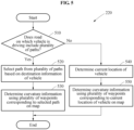
- FIG. 5 illustrates an example of a method of determining curvature information when a vehicle is driving on a road including a plurality of paths such as an intersection or a returning lane.
- the operations in FIG. 5 may be performed in the sequence and manner as shown, although the order of some operations may be changed or some of the operations omitted without departing from the scope of the illustrative examples described. Many of the operations shown in FIG. 5 may be performed in parallel or concurrently.
- One or more blocks of FIG. 5 , and combinations of the blocks, can be implemented by special purpose hardware-based computer that perform the specified functions, or combinations of special purpose hardware and computer instructions.
- FIG. 5 will be described below with respect to an information providing apparatus, such as corresponding to the information providing apparatus of any of FIGS. 1A and 1B .
- an information providing apparatus determines whether a road on which a vehicle is driving includes a plurality of paths.
- the information providing apparatus determines whether the road on which the vehicle is driving includes the plurality of paths based on, for example, map information and GPS information.
- the information providing apparatus selects a path from the plurality of paths based on destination information of the vehicle in operation 520.
- a destination of the vehicle is a city A and a road on which the vehicle is driving includes a path toward a city B and a path toward a city C.
- the information providing apparatus selects the path toward the city B among the path toward the city B and the path toward the city C based on information regarding the destination corresponding to the city A.
- the information providing apparatus determines curvature information using a plurality of waypoints corresponding to the selected path on a map.
- the information providing apparatus determines a current location of the vehicle in operation 540 and determines curvature information using a plurality of waypoints corresponding to the current location of the vehicle on the map in operation 550.
- FIG. 6 illustrates an example of a method of estimating a lateral offset of a vehicle.
- the operations in FIG. 6 may be performed in the sequence and manner as shown, although the order of some operations may be changed or some of the operations omitted without departing from the scope of the illustrative examples described. Many of the operations shown in FIG. 6 may be performed in parallel or concurrently.
- One or more blocks of FIG. 6 , and combinations of the blocks, can be implemented by special purpose hardware-based computer that perform the specified functions, or combinations of special purpose hardware and computer instructions.
- FIG. 6 will be described below with respect to an information providing apparatus, such as corresponding to the information providing apparatus of any of FIGS. 1A and 1B .
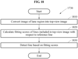
- an information providing apparatus converts an image of a lane region into a top-view image.
- the information providing apparatus converts the image of the lane region into the top-view image by multiplying the image by a homography matrix.
- the top-view image is also referred to as "a bird's eye view (BEV) image.”
- the information providing apparatus may employ an inverse perspective mapping (IPM) scheme to convert the image of the lane region into the top-view image.
- IPM inverse perspective mapping
- the information providing apparatus calculates fitting scores of lines included in the top-view image with respect to a reference line.
- the top-view image may include a first line, a second line, and a third line.
- the information providing apparatus calculates a fitting score of the first line with respect to the reference line and a fitting score of the second line with respect to the reference line.
- the information providing apparatus calculates a fitting score of the third line with respect to the reference line.
- the information providing apparatus estimates a lateral offset of the vehicle based on the fitting scores.
- a method of estimating, by the information providing apparatus, a lateral offset of a vehicle will be further described with reference to FIG. 8 .
- FIG. 7 illustrates an example of a method of calculating fitting scores.
- the operations in FIG. 7 may be performed in the sequence and manner as shown, although the order of some operations may be changed or some of the operations omitted without departing from the scope of the illustrative examples described. Many of the operations shown in FIG. 7 may be performed in parallel or concurrently.
- One or more blocks of FIG. 7 , and combinations of the blocks, can be implemented by special purpose hardware-based computer that perform the specified functions, or combinations of special purpose hardware and computer instructions.
- FIG. 7 will be described below with respect to an information providing apparatus, such as corresponding to the information providing apparatus of any of FIGS. 1A and 1B .
- an information providing apparatus moves a reference line by a predetermined number of pixel units.
- the information providing apparatus moves the reference line from one end of a top-view image toward the other end of the top-view image.
- the reference line may be moved in a horizontal direction in the top-view image by a predetermined number of pixel units.
- the information providing apparatus moves the reference line, for example, by one pixel, or two pixels, or three pixels.
- the information providing apparatus counts a number of matching pixels between lines (for example, a first line, a second line, and a third line) included in the top-view image and the reference line moved by pixel units.
- Each of the lines included in the top-view image has a thickness corresponding to a plurality of pixels.
- a predetermined pixel unit by which the reference line is moved may be less than a number of pixels corresponding to the thickness of each of the lines.
- a matching operation may be performed on each of the lines a plurality of times.
- the information providing apparatus calculates a candidate fitting score associated with the reference line moved by a predetermined number of pixel units based on the number of matching pixels.
- the candidate fitting score is a result of fitting performed based on a lateral position of the reference line moved by a predetermined number of pixel units before classifying a plurality of lines.
- the information providing apparatus calculates candidate fitting scores by repetitively performing the foregoing process of FIG. 7 .
- the information providing apparatus classifies the plurality of lines using the candidate fitting scores.
- a candidate fitting score corresponding to a predetermined lateral position is greater than a threshold, a line corresponding to the lateral position is classified as a lane boundary.
- a candidate fitting score corresponding to a predetermined lateral position is less than or equal to the threshold, it is recognized that a line corresponding to the lateral position is not a lane boundary.
- at least a preset number (for example, one or more) of lines that are not recognized as the lane boundary are detected consecutively, it is recognized that different lines are present on left and right sides of the corresponding line.
- the information providing apparatus detects a lane boundary based on candidate fitting scores corresponding to lines classified as the lane boundary (hereinafter, also referred to as "fitting scores").
- the information providing apparatus may discard candidate fitting scores having values less than or equal to the threshold, for example, 0.4, among the candidate fitting scores as shown in Table 1. Also, the information providing apparatus determines candidate fitting scores having values greater than 0.4 to be fitting scores corresponding to the second line.
Landscapes
- Engineering & Computer Science (AREA)
- Physics & Mathematics (AREA)
- Radar, Positioning & Navigation (AREA)
- Remote Sensing (AREA)
- General Physics & Mathematics (AREA)
- Automation & Control Theory (AREA)
- Theoretical Computer Science (AREA)
- Computer Vision & Pattern Recognition (AREA)
- Transportation (AREA)
- Mechanical Engineering (AREA)
- Mathematical Physics (AREA)
- Multimedia (AREA)
- Data Mining & Analysis (AREA)
- Electromagnetism (AREA)
- Human Computer Interaction (AREA)
- Aviation & Aerospace Engineering (AREA)
- Bioinformatics & Computational Biology (AREA)
- Evolutionary Biology (AREA)
- Bioinformatics & Cheminformatics (AREA)
- Artificial Intelligence (AREA)
- General Engineering & Computer Science (AREA)
- Life Sciences & Earth Sciences (AREA)
- Evolutionary Computation (AREA)
- Traffic Control Systems (AREA)
- Navigation (AREA)
- Image Analysis (AREA)
- Control Of Driving Devices And Active Controlling Of Vehicle (AREA)
Claims (13)
- Verfahren zum Bereitstellen von Informationen zum Fahren eines Fahrzeugs, umfassend:Bestimmen (1045) von Krümmungsinformationen einer Straße, auf der ein Fahrzeug fährt, basierend auf Karteninformationen;Erfassen (1010) eines Fahrspurbereichs, der Fahrspurbegrenzungslinien enthält, aus einem Fahrbild, umfassend:Erzeugen eines Segmentierungsbildes, das zwischen Pixeln einer Linienklasse und Pixeln einer anderen Klasse als der Linienklasse unterscheidet (1120);Erfassen eines Fahrspurbereichsbildes, das Pixel enthält, die als Linienklasse klassifiziert sind, aus dem Segmentierungsbild;Konvertieren (1050) des Fahrspurbereichsbildes (1410) in ein Bild in der Draufsicht (1430) durch Anwenden einer inversen perspektivischen Transformation auf den Fahrspurbereich;Schätzen (1070) eines seitlichen Versatzes (1530) des Fahrzeugs von einer Mittellinie (1540) einer Fahrspur, auf der das Fahrzeug fährt, basierend auf dem Bild in der Draufsicht (1430), dem Fahrspurbereich und einer Referenzlinie (1510), die aus den Krümmungsinformationen gebildet wird; undAusgeben (1080) eines Signals, das Informationen zum Fahren des Fahrzeugs enthält, basierend auf den Krümmungsinformationen und dem seitlichen Versatz.
- Verfahren nach Anspruch 1, ferner umfassend das Erfassen einer Linie auf der Straße basierend auf dem Fahrspurbereich und der Referenzlinie basierend auf den Krümmungsinformationen, wobei das Schätzen des seitlichen Versatzes auf der erfassten Linie basiert.
- Verfahren nach Anspruch 1 oder 2, wobei das Erfassen des Fahrspurbereichs Folgendes umfasst:Klassifizieren eines Objekts, das in dem Fahrbild enthalten ist;Erzeugen eines Segmentierungsbildes, in dem das in dem Fahrbild enthaltene Objekt klassifiziert wird; undErfassen des Fahrspurbereichs aus dem erzeugten Segmentierungsbild.
- Verfahren nach einem der Ansprüche 1 bis 3, wobei das Bestimmen der Krümmungsinformationen Folgendes umfasst:Bestimmen eines aktuellen Standorts des Fahrzeugs; undBestimmen der Krümmungsinformationen basierend auf einer Vielzahl von Wegpunkten (130, ..., 140) innerhalb eines Vorausschauabstands zwischen einem ersten Wegpunkt (130) neben einem aktuellen Standort des Fahrzeugs auf einer Karte und einem zweiten Wegpunkt (140) auf der Karte;wobei vorzugsweise zumindest eines der Folgenden zutrifft:
das Bestimmen der Krümmungsinformationen basierend auf den Wegpunkten umfasst Folgendes:Auswählen der Wegpunkte innerhalb eines Vorausschauabstands von dem aktuellen Standort aus, wobei der Vorausschauabstand dann vorzugsweise basierend auf einer oder einer Kombination aus einer Geschwindigkeit des Fahrzeugs, einer sichtbaren Entfernung, einer Wetterbedingung, einer Fahrbedingung und einer Straßenbedingung bestimmt wird;das Bestimmen der Krümmungsinformationen basierend auf den Wegpunkten umfasst Folgendes:Erkennen einer Form der Straße auf der Karte basierend auf den Wegpunkten; undBestimmen der Krümmungsinformationen basierend auf der Form der Straße auf der Karte, wobei das Erkennen der Form der Straße auf der Karte vorzugsweise Folgendes umfasst:
Erhalten einer Regressionsfunktion, die die Form der Straße auf der Karte ausdrückt, und zwar mit einer linearen Regressionsanalyse an den Wegpunkten. - Verfahren nach einem der Ansprüche 1 bis 4, wobei das Bestimmen der Krümmungsinformationen Folgendes umfasst:wenn die Straße, auf der das Fahrzeug fährt, eine Vielzahl von Wegen enthält, Auswählen eines der Wege basierend auf Zielinformationen des Fahrzeugs; undBestimmen von Krümmungsinformationen einer Straße, die dem ausgewählten Weg entspricht.
- Verfahren nach einem der Ansprüche 1 bis 5, wobei das Schätzen des seitlichen Versatzes des Fahrzeugs Folgendes umfasst:Berechnen von polynomialen Anpassungsbewertungen von Linien, die in dem Bild in der Draufsicht enthalten sind, in Bezug auf die Referenzlinie; undSchätzen eines seitlichen Versatzes des Fahrzeugs basierend auf den polynomialen Anpassungsbewertungen.
- Verfahren nach Anspruch 6, wobei das Schätzen des seitlichen Versatzes Folgendes umfasst:Erfassen einer Linie auf der Straße basierend auf den polynomialen Anpassungsbewertungen;Schätzen des seitlichen Versatzes basierend auf der erfassten Linie.
- Verfahren nach Anspruch 6 oder 7, wobei das Berechnen der polynomialen Anpassungsbewertungen Folgendes umfasst:
während die Referenzlinie um eine vorbestimmte Anzahl von Pixeleinheiten verschoben wird, Berechnen von Kandidatenanpassungsbewertungen als Reaktion auf das Verschieben der Referenzlinie, indem eine Anzahl von abgestimmten Pixeln zwischen den in dem Bild in der Draufsicht enthaltenen Linien und der Referenzlinie gezählt wird, wobei das Berechnen der Kandidatenanpassungsbewertungen vorzugsweise Folgendes umfasst:Verschieben der Referenzlinie um die vorbestimmte Anzahl von Pixeleinheiten;Zählen einer Anzahl von abgestimmten Pixeln zwischen den in dem Bild in der Draufsicht enthaltenen Linien und der um die vorbestimmte Anzahl von Pixeleinheiten verschobenen Referenzlinie; undBerechnen einer der verschobenen Referenzlinie zugeordneten Kandidatenanpassungsbewertung basierend auf der Anzahl der abgestimmten Pixel. - Verfahren nach Anspruch 7 oder 8, wobei das Schätzen des seitlichen Versatzes des Fahrzeugs Folgendes umfasst:Erfassen von Linien basierend auf den polynomialen Anpassungsbewertungen; undBerechnen des seitlichen Versatzes basierend auf den erfassten Linien und einer seitlichen Position des Fahrzeugs in dem Bild in der Draufsicht;wobei vorzugsweise zumindest eines der Folgenden zutrifft:das Erfassen der Linien umfasst Folgendes:Bestimmen zumindest einer polynomialen Anpassungsbewertung, die jeder Linie unter den Anpassungsbewertungen entspricht, basierend auf einem Schwellenwert; undErfassen einer entsprechenden Linie basierend auf der zumindest einen polynomialen Anpassungsbewertung, die jeder Linie entspricht, wobei das Erfassen der entsprechenden Linie dann vorzugsweise Folgendes umfasst:Erfassen einer polynomialen Anpassungsbewertung, die einen höchsten Wert aufweist, aus mindestens einer polynomialen Anpassungsbewertung der entsprechenden Linie; undBestimmen der entsprechenden Linie basierend auf Versatzinformationen, die der erfassten polynomialen Anpassungsbewertung entsprechen, oderErhalten einer gewichteten Summe von mindestens einer Versatzinformation, die der mindestens einen polynomialen Anpassungsbewertung entspricht, basierend auf mindestens einer polynomialen Anpassungsbewertung der entsprechenden Linie, als eine Gewichtung; undBestimmen der entsprechenden Linie basierend auf der gewichteten Summe;die Berechnung des seitlichen Versatzes umfasst Folgendes:Bestimmen einer Mittellinie zwischen einer linken und einer rechten Linie, die an die seitliche Position des Fahrzeugs angrenzt; undBerechnen einer Entfernung zwischen der Mittellinie und der seitlichen Position des Fahrzeugs; wobei die seitliche Position des Fahrzeugs in dem Bild in der Draufsicht eine seitlich zentrale Position des Bildes in der Draufsicht enthält;die seitliche Position des Fahrzeugs in dem Bild in der Draufsicht wird bestimmt basierend auf einer seitlichen Position einer Kamera, die an dem Fahrzeug angebracht ist, um das Fahrbild aufzunehmen.
- Verfahren nach einem der Ansprüche 1 bis 9, wobei das Ausgeben des Signals, das die Informationen zum Fahren des Fahrzeugs enthält, Folgendes umfasst:Bestimmen eines lokalen Weges des Fahrzeugs basierend auf den Krümmungsinformationen und dem seitlichen Versatz; undErzeugen eines Signals zum Steuern des Fahrens des Fahrzeugs basierend auf dem lokalen Weg und/oder Bereitstellen von Fahrinformationen, die einen Fahrweg des Fahrzeugs basierend auf dem lokalen Weg enthalten;und/wobei das Verfahren ferner Folgendes umfasst:Erhalten des Fahrbildes; undErhalten der Karteninformationen.
- Übergangsloses, computerlesbares Speichermedium, auf dem Anweisungen gespeichert sind, die, wenn sie von einem Prozessor ausgeführt werden, bewirken, dass der Prozessor das Verfahren nach einem der vorhergehenden Ansprüche durchführt.
- Vorrichtung (1900) zur Bereitstellung von Informationen zum Fahren eines Fahrzeugs, umfassend Sensoren (1910), eine Kommunikationsschnittstelle (1920), einen Speicher (1940), eine Anzeige (1950) und einen Prozessor (1930), wobei der Prozessor konfiguriert ist, um das Verfahren nach einem der Ansprüche 1 bis 10 durchzuführen.
- Vorrichtung nach Anspruch 12, wobei das Erfassen des Fahrspurbereichs, der FahrspurBegrenzungslinien enthält, aus dem Fahrbild das Erfassen der Fahrspurbegrenzungslinie unter Verwendung des Fahrspurbereichs und einer Referenzlinie basierend auf den Krümmungsinformationen umfasst.
Applications Claiming Priority (1)
| Application Number | Priority Date | Filing Date | Title |
|---|---|---|---|
| KR1020180016904A KR102541561B1 (ko) | 2018-02-12 | 2018-02-12 | 차량의 주행을 위한 정보를 제공하는 방법 및 그 장치들 |
Publications (2)
| Publication Number | Publication Date |
|---|---|
| EP3524936A1 EP3524936A1 (de) | 2019-08-14 |
| EP3524936B1 true EP3524936B1 (de) | 2025-03-26 |
Family
ID=64048971
Family Applications (1)
| Application Number | Title | Priority Date | Filing Date |
|---|---|---|---|
| EP18203797.8A Active EP3524936B1 (de) | 2018-02-12 | 2018-10-31 | Verfahren und vorrichtung zur bereitstellung von informationen für ein fahrendes fahrzeug |
Country Status (5)
| Country | Link |
|---|---|
| US (1) | US11113544B2 (de) |
| EP (1) | EP3524936B1 (de) |
| JP (1) | JP7349792B2 (de) |
| KR (1) | KR102541561B1 (de) |
| CN (1) | CN110155053B (de) |
Families Citing this family (56)
| Publication number | Priority date | Publication date | Assignee | Title |
|---|---|---|---|---|
| JP7022624B2 (ja) * | 2018-03-13 | 2022-02-18 | 株式会社ディスコ | 位置付け方法 |
| JP7022197B2 (ja) * | 2018-03-15 | 2022-02-17 | パイオニア株式会社 | レーン情報生成方法 |
| US11816585B2 (en) * | 2018-12-03 | 2023-11-14 | Tesla, Inc. | Machine learning models operating at different frequencies for autonomous vehicles |
| KR102733277B1 (ko) * | 2019-02-21 | 2024-11-21 | 현대자동차주식회사 | 저비용 자율 주행 셔틀 운행 방법 및 장치 |
| EP3971048B1 (de) * | 2019-05-15 | 2023-06-07 | NISSAN MOTOR Co., Ltd. | Fahrzeugfahrtsteuerungsverfahren und fahrzeugfahrtsteuerungsvorrichtung |
| CN110525342A (zh) * | 2019-08-30 | 2019-12-03 | 的卢技术有限公司 | 一种基于深度学习的ar-hud车载辅助驾驶方法及其系统 |
| CN112441012B (zh) * | 2019-09-05 | 2023-05-12 | 北京地平线机器人技术研发有限公司 | 车辆行驶轨迹预测方法和装置 |
| CN111361638B (zh) * | 2019-10-12 | 2020-12-08 | 北汽福田汽车股份有限公司 | 车辆感知装置的控制方法、装置、可读存储介质及车辆 |
| CN112785595B (zh) * | 2019-11-07 | 2023-02-28 | 北京市商汤科技开发有限公司 | 目标属性检测、神经网络训练及智能行驶方法、装置 |
| CN111123740B (zh) * | 2019-12-19 | 2024-04-16 | 北京经纬恒润科技股份有限公司 | 硬件在环测试方法以及装置 |
| CN113104037B (zh) * | 2019-12-24 | 2022-08-30 | 浙江吉利汽车研究院有限公司 | 一种车辆方向盘转向角度确定方法及系统 |
| CN111152721B (zh) * | 2019-12-31 | 2022-09-02 | 合肥疆程技术有限公司 | 一种绘制车道的引导线的方法、装置及抬头显示系统 |
| US12238675B2 (en) | 2020-01-09 | 2025-02-25 | Lg Electronics Inc. | Method for transmitting, by apparatus, CPM in wireless communication system supporting sidelink, and apparatus therefor |
| CN113155143B (zh) * | 2020-01-23 | 2024-10-18 | 宝马股份公司 | 用于评估自动驾驶用的地图的方法、设备和车辆 |
| JP7359715B2 (ja) * | 2020-02-14 | 2023-10-11 | 株式会社Soken | 道路形状推定装置 |
| FR3107763B1 (fr) * | 2020-02-28 | 2022-01-28 | Continental Automotive | Procédé de cartographie tri-dimensionnelle et calculateur associé |
| KR20210112672A (ko) * | 2020-03-05 | 2021-09-15 | 삼성전자주식회사 | 객체를 검출하기 위한 프로세서 및 객체 검출 방법 |
| US11391596B2 (en) * | 2020-04-28 | 2022-07-19 | Vgis Inc. | System and method for converging mediated reality positioning data and geographic positioning data |
| CN112639814B (zh) * | 2020-05-29 | 2022-02-11 | 华为技术有限公司 | 一种路况检测方法和装置 |
| CN111824143A (zh) * | 2020-07-22 | 2020-10-27 | 中国第一汽车股份有限公司 | 一种车辆横向控制方法、装置、计算机设备和存储介质 |
| JP7557796B2 (ja) * | 2020-10-29 | 2024-09-30 | パナソニックIpマネジメント株式会社 | 処理方法およびそれを利用した処理装置 |
| US12131557B2 (en) * | 2020-11-10 | 2024-10-29 | Nec Corporation | End-to-end parametric road layout prediction with cheap supervision |
| CN112415552B (zh) * | 2020-11-17 | 2022-04-15 | 北京百度网讯科技有限公司 | 车辆位置的确定方法、装置及电子设备 |
| JP7556406B2 (ja) * | 2020-12-03 | 2024-09-26 | 日本電気株式会社 | ライン位置推定装置、方法およびプログラム |
| US12031829B2 (en) * | 2020-12-03 | 2024-07-09 | Motional Ad Llc | Localization based on surrounding vehicles |
| CN112710301B (zh) * | 2020-12-09 | 2023-01-06 | 上汽大众汽车有限公司 | 一种自动驾驶车辆高精度定位方法和系统 |
| CN113052904B (zh) * | 2021-03-19 | 2022-12-13 | 上海商汤临港智能科技有限公司 | 一种定位方法、装置、电子设备及存储介质 |
| CN113022570B (zh) * | 2021-03-19 | 2022-06-10 | 武汉理工大学 | 一种车辆换道行为识别方法及设备 |
| JP2022149451A (ja) * | 2021-03-25 | 2022-10-06 | 本田技研工業株式会社 | 車両用表示制御装置、車両用表示制御装置の制御方法、およびプログラム |
| CN115140037B (zh) * | 2021-03-31 | 2025-08-12 | 上海汽车集团股份有限公司 | 一种确定车辆行驶边界的方法及装置 |
| KR102572336B1 (ko) * | 2021-04-23 | 2023-08-30 | 한국전자기술연구원 | 주행 계획 장치 및 방법, 이를 적용한 이동 로봇 |
| CN115489511B (zh) * | 2021-06-17 | 2025-11-04 | 上海飞机制造有限公司 | 智能运输车转向速度控制方法、装置、介质及电子设备 |
| CN113232658B (zh) * | 2021-06-28 | 2022-06-28 | 驭势(上海)汽车科技有限公司 | 一种车辆定位方法、装置、电子设备和存储介质 |
| US12330639B1 (en) * | 2021-07-21 | 2025-06-17 | Mobileye Vision Technologies, Ltd. | Identifying lane markings using a trained model |
| US20230063809A1 (en) * | 2021-08-25 | 2023-03-02 | GM Global Technology Operations LLC | Method for improving road topology through sequence estimation and anchor point detetection |
| CN113869203B (zh) * | 2021-09-27 | 2025-01-14 | 奥特酷智能科技(南京)有限公司 | 车辆定位方法和系统 |
| CN113830174B (zh) * | 2021-09-28 | 2022-12-09 | 广州文远知行科技有限公司 | 一种转向角度修正方法、装置、设备及可读存储介质 |
| MX2024004885A (es) * | 2021-10-22 | 2024-07-19 | Huawei Tech Co Ltd | Vehículo, método y aparato de posicionamiento del vehículo, dispositivo y medio de almacenamiento legible por computadora. |
| KR20230071556A (ko) * | 2021-11-16 | 2023-05-23 | 현대자동차주식회사 | 차량의 주행 제어 장치 및 그 방법 |
| KR102433544B1 (ko) * | 2022-01-14 | 2022-08-18 | 주식회사 카비 | 순차 영상 분석을 통한 차량경로 복원 시스템 및 이를 이용한 차량경로 복원 방법 |
| CN114518123B (zh) * | 2022-02-24 | 2024-06-11 | 高德软件有限公司 | 信息处理方法 |
| CN114565904A (zh) * | 2022-03-02 | 2022-05-31 | 北京百度网讯科技有限公司 | 确定可行驶区域的方法、装置、设备、介质和车辆 |
| KR102523146B1 (ko) * | 2022-03-28 | 2023-04-18 | 주식회사 라이드플럭스 | 차량의 자율주행을 위한 주행 경로 모델링 방법, 장치 및 컴퓨터프로그램 |
| CN114559946B (zh) * | 2022-03-31 | 2025-03-07 | 北京主线科技有限公司 | 一种参考线确定方法、装置、设备及介质 |
| DE102022109576B4 (de) | 2022-04-20 | 2024-06-27 | Bayerische Motoren Werke Aktiengesellschaft | System, verfahren und software zum anzeigen einer abstandsmarkierung |
| CN117087694A (zh) * | 2022-05-13 | 2023-11-21 | 武汉智行者科技有限公司 | 一种车辆行驶参考线生成方法、系统及移动工具 |
| US12454264B2 (en) * | 2022-09-02 | 2025-10-28 | Autobrains Technologies Ltd | Polynomial prediction of road lane metadata |
| CN115123218B (zh) * | 2022-09-02 | 2022-11-22 | 小米汽车科技有限公司 | 车辆的检测方法、装置及其电子设备 |
| US12014555B2 (en) * | 2022-11-07 | 2024-06-18 | Plusai, Inc. | Vehicle localization based on lane templates |
| US12240492B2 (en) * | 2022-12-08 | 2025-03-04 | GM Global Technology Operations LLC | Methods and systems for vehicle control under degraded lane perception range |
| US12380710B2 (en) * | 2022-12-30 | 2025-08-05 | Rivian Ip Holdings, Llc | System and method for deep learning based lane curvature detection from 2D images |
| CN116147650B (zh) * | 2023-02-27 | 2025-08-05 | 重庆长安汽车股份有限公司 | 一种车道组合筛选方法、装置、设备及存储介质 |
| CN117218193B (zh) * | 2023-09-05 | 2026-01-06 | 斑马网络技术股份有限公司 | 真实物体的虚实贴合方法、智能座舱、介质及智能汽车 |
| CN116935349B (zh) * | 2023-09-15 | 2023-11-28 | 华中科技大学 | 一种基于Zigzag变换的车道线检测方法、系统、设备及介质 |
| CN117132863B (zh) * | 2023-10-25 | 2023-12-22 | 罗普特科技集团股份有限公司 | 一种能够进行数据反馈的车辆系统 |
| CN118915777B (zh) * | 2024-10-10 | 2024-12-17 | 合肥工业大学 | 一种智能客车跟踪预定轨迹的控制方法 |
Family Cites Families (31)
| Publication number | Priority date | Publication date | Assignee | Title |
|---|---|---|---|---|
| JP4277717B2 (ja) * | 2004-03-17 | 2009-06-10 | 株式会社日立製作所 | 車両位置推定装置およびこれを用いた運転支援装置 |
| JP4716703B2 (ja) | 2004-10-05 | 2011-07-06 | アルパイン株式会社 | ナビゲーション装置及びマップマッチング方法 |
| DE102006011481A1 (de) * | 2006-03-13 | 2007-09-20 | Robert Bosch Gmbh | Verfahren und Vorrichtung zum Unterstützen eines Führens eines Fahrzeugs |
| US8064643B2 (en) | 2006-12-06 | 2011-11-22 | Mobileye Technologies Limited | Detecting and recognizing traffic signs |
| DE102008003666A1 (de) | 2008-01-09 | 2009-07-16 | Robert Bosch Gmbh | Verfahren für die Steuerung eines Fahrerassistenzsystems und Fahrerassistenzsystem |
| US8605947B2 (en) | 2008-04-24 | 2013-12-10 | GM Global Technology Operations LLC | Method for detecting a clear path of travel for a vehicle enhanced by object detection |
| JP5187171B2 (ja) | 2008-12-05 | 2013-04-24 | トヨタ自動車株式会社 | 車線逸脱警報システム |
| US8912978B2 (en) | 2009-04-02 | 2014-12-16 | GM Global Technology Operations LLC | Dynamic vehicle system information on full windshield head-up display |
| US8977489B2 (en) | 2009-05-18 | 2015-03-10 | GM Global Technology Operations LLC | Turn by turn graphical navigation on full windshield head-up display |
| EP2602154B1 (de) | 2010-08-06 | 2016-03-30 | Toyota Jidosha Kabushiki Kaisha | Vorrichtung und verfahren zur steuerung der lichtverteilung bei einem fahrzeug |
| US8447519B2 (en) | 2010-11-10 | 2013-05-21 | GM Global Technology Operations LLC | Method of augmenting GPS or GPS/sensor vehicle positioning using additional in-vehicle vision sensors |
| KR20120072020A (ko) * | 2010-12-23 | 2012-07-03 | 한국전자통신연구원 | 자율주행 시스템의 주행정보 인식 방법 및 장치 |
| US8457827B1 (en) | 2012-03-15 | 2013-06-04 | Google Inc. | Modifying behavior of autonomous vehicle based on predicted behavior of other vehicles |
| US9482536B2 (en) | 2012-05-31 | 2016-11-01 | International Electronic Machines Corp. | Pose estimation |
| US9327765B2 (en) | 2012-10-04 | 2016-05-03 | Nissan Motor Co., Ltd. | Steering control device |
| TWI523778B (zh) | 2013-11-04 | 2016-03-01 | Lane offset warning system and method | |
| US9656673B2 (en) | 2013-12-04 | 2017-05-23 | Mobileye Vision Technologies Ltd. | Systems and methods for navigating a vehicle to a default lane |
| JP6390095B2 (ja) * | 2013-12-18 | 2018-09-19 | 株式会社ジェイテクト | 車両制御装置 |
| WO2015116950A1 (en) | 2014-01-30 | 2015-08-06 | Anna Clarke | Systems and methods for lane end recognition |
| KR101573764B1 (ko) | 2014-07-28 | 2015-12-02 | 현대모비스 주식회사 | 차량의 주행 차로 인식 시스템 및 방법 |
| KR102157810B1 (ko) * | 2014-09-29 | 2020-09-18 | 현대모비스 주식회사 | 내비게이션 시스템의 지도 매칭 장치 및 방법 |
| KR101635831B1 (ko) * | 2014-11-27 | 2016-07-05 | 연세대학교 산학협력단 | 차량 위치 인식 장치 및 방법 |
| JP6506625B2 (ja) * | 2015-05-29 | 2019-04-24 | 株式会社デンソー | 運転支援装置及び運転支援方法 |
| US11125566B2 (en) | 2015-07-16 | 2021-09-21 | Ford Global Technologies, Llc | Method and apparatus for determining a vehicle ego-position |
| US10013610B2 (en) | 2015-10-23 | 2018-07-03 | Nokia Technologies Oy | Integration of positional data and overhead images for lane identification |
| US10102434B2 (en) | 2015-12-22 | 2018-10-16 | Omnivision Technologies, Inc. | Lane detection system and method |
| JP6604209B2 (ja) * | 2016-01-12 | 2019-11-13 | トヨタ自動車株式会社 | 運転支援装置 |
| US20170248958A1 (en) | 2016-02-25 | 2017-08-31 | Delphi Technologies, Inc. | Adjacent lane verification for an automated vehicle |
| JP6460349B2 (ja) * | 2016-04-13 | 2019-01-30 | トヨタ自動車株式会社 | 車両走行制御装置 |
| WO2019094843A1 (en) * | 2017-11-10 | 2019-05-16 | Nvidia Corporation | Systems and methods for safe and reliable autonomous vehicles |
| JP6525413B1 (ja) * | 2017-12-28 | 2019-06-05 | マツダ株式会社 | 車両制御装置 |
-
2018
- 2018-02-12 KR KR1020180016904A patent/KR102541561B1/ko active Active
- 2018-09-26 US US16/142,257 patent/US11113544B2/en active Active
- 2018-10-25 CN CN201811247356.XA patent/CN110155053B/zh active Active
- 2018-10-31 EP EP18203797.8A patent/EP3524936B1/de active Active
-
2019
- 2019-02-01 JP JP2019016926A patent/JP7349792B2/ja active Active
Also Published As
| Publication number | Publication date |
|---|---|
| JP7349792B2 (ja) | 2023-09-25 |
| JP2019139762A (ja) | 2019-08-22 |
| KR102541561B1 (ko) | 2023-06-08 |
| CN110155053A (zh) | 2019-08-23 |
| CN110155053B (zh) | 2024-04-05 |
| KR20190097453A (ko) | 2019-08-21 |
| EP3524936A1 (de) | 2019-08-14 |
| US20190251373A1 (en) | 2019-08-15 |
| US11113544B2 (en) | 2021-09-07 |
Similar Documents
| Publication | Publication Date | Title |
|---|---|---|
| EP3524936B1 (de) | Verfahren und vorrichtung zur bereitstellung von informationen für ein fahrendes fahrzeug | |
| US11294392B2 (en) | Method and apparatus for determining road line | |
| US11204253B2 (en) | Method and apparatus for displaying virtual route | |
| US11842447B2 (en) | Localization method and apparatus of displaying virtual object in augmented reality | |
| US11176719B2 (en) | Method and apparatus for localization based on images and map data | |
| EP3640599B1 (de) | Fahrzeugortungsverfahren und -vorrichtung | |
| EP3462377B1 (de) | Verfahren und vorrichtung zur identifizierung einer fahrspur | |
| US11670087B2 (en) | Training data generating method for image processing, image processing method, and devices thereof | |
| US11720992B2 (en) | Method, apparatus, and computer program product for generating an overhead view of an environment from a perspective image | |
| US10331957B2 (en) | Method, apparatus, and system for vanishing point/horizon estimation using lane models | |
| US10891795B2 (en) | Localization method and apparatus based on 3D color map | |
| EP3493108A1 (de) | Spurhalteverfahren und -vorrichtung | |
| US10853667B2 (en) | Method and apparatus with linearity detection | |
| US20240119740A1 (en) | Method and apparatus with lane line determination | |
| EP4641524A1 (de) | Verfahren, vorrichtung und vorrichtung mit fahrzeugpositionsbestimmung | |
| US20250069257A1 (en) | Method and apparatus with image frame information determination |
Legal Events
| Date | Code | Title | Description |
|---|---|---|---|
| PUAI | Public reference made under article 153(3) epc to a published international application that has entered the european phase |
Free format text: ORIGINAL CODE: 0009012 |
|
| STAA | Information on the status of an ep patent application or granted ep patent |
Free format text: STATUS: THE APPLICATION HAS BEEN PUBLISHED |
|
| AK | Designated contracting states |
Kind code of ref document: A1 Designated state(s): AL AT BE BG CH CY CZ DE DK EE ES FI FR GB GR HR HU IE IS IT LI LT LU LV MC MK MT NL NO PL PT RO RS SE SI SK SM TR |
|
| AX | Request for extension of the european patent |
Extension state: BA ME |
|
| STAA | Information on the status of an ep patent application or granted ep patent |
Free format text: STATUS: REQUEST FOR EXAMINATION WAS MADE |
|
| 17P | Request for examination filed |
Effective date: 20200213 |
|
| RBV | Designated contracting states (corrected) |
Designated state(s): AL AT BE BG CH CY CZ DE DK EE ES FI FR GB GR HR HU IE IS IT LI LT LU LV MC MK MT NL NO PL PT RO RS SE SI SK SM TR |
|
| STAA | Information on the status of an ep patent application or granted ep patent |
Free format text: STATUS: EXAMINATION IS IN PROGRESS |
|
| 17Q | First examination report despatched |
Effective date: 20220407 |
|
| P01 | Opt-out of the competence of the unified patent court (upc) registered |
Effective date: 20230520 |
|
| RIC1 | Information provided on ipc code assigned before grant |
Ipc: G08G 1/16 20060101ALI20240708BHEP Ipc: G01C 21/36 20060101AFI20240708BHEP |
|
| GRAP | Despatch of communication of intention to grant a patent |
Free format text: ORIGINAL CODE: EPIDOSNIGR1 |
|
| STAA | Information on the status of an ep patent application or granted ep patent |
Free format text: STATUS: GRANT OF PATENT IS INTENDED |
|
| INTG | Intention to grant announced |
Effective date: 20241122 |
|
| RIN1 | Information on inventor provided before grant (corrected) |
Inventor name: LEE, JAEWOO Inventor name: LEE, DONGWOOK Inventor name: KOO, JAHOO Inventor name: LEE, WONJU |
|
| GRAS | Grant fee paid |
Free format text: ORIGINAL CODE: EPIDOSNIGR3 |
|
| GRAA | (expected) grant |
Free format text: ORIGINAL CODE: 0009210 |
|
| STAA | Information on the status of an ep patent application or granted ep patent |
Free format text: STATUS: THE PATENT HAS BEEN GRANTED |
|
| AK | Designated contracting states |
Kind code of ref document: B1 Designated state(s): AL AT BE BG CH CY CZ DE DK EE ES FI FR GB GR HR HU IE IS IT LI LT LU LV MC MK MT NL NO PL PT RO RS SE SI SK SM TR |
|
| REG | Reference to a national code |
Ref country code: GB Ref legal event code: FG4D |
|
| REG | Reference to a national code |
Ref country code: CH Ref legal event code: EP |
|
| REG | Reference to a national code |
Ref country code: DE Ref legal event code: R096 Ref document number: 602018080423 Country of ref document: DE |
|
| REG | Reference to a national code |
Ref country code: IE Ref legal event code: FG4D |
|
| REG | Reference to a national code |
Ref country code: NL Ref legal event code: FP |
|
| PG25 | Lapsed in a contracting state [announced via postgrant information from national office to epo] |
Ref country code: RS Free format text: LAPSE BECAUSE OF FAILURE TO SUBMIT A TRANSLATION OF THE DESCRIPTION OR TO PAY THE FEE WITHIN THE PRESCRIBED TIME-LIMIT Effective date: 20250626 |
|
| PG25 | Lapsed in a contracting state [announced via postgrant information from national office to epo] |
Ref country code: FI Free format text: LAPSE BECAUSE OF FAILURE TO SUBMIT A TRANSLATION OF THE DESCRIPTION OR TO PAY THE FEE WITHIN THE PRESCRIBED TIME-LIMIT Effective date: 20250326 |
|
| REG | Reference to a national code |
Ref country code: LT Ref legal event code: MG9D |
|
| PG25 | Lapsed in a contracting state [announced via postgrant information from national office to epo] |
Ref country code: NO Free format text: LAPSE BECAUSE OF FAILURE TO SUBMIT A TRANSLATION OF THE DESCRIPTION OR TO PAY THE FEE WITHIN THE PRESCRIBED TIME-LIMIT Effective date: 20250626 |
|
| PG25 | Lapsed in a contracting state [announced via postgrant information from national office to epo] |
Ref country code: HR Free format text: LAPSE BECAUSE OF FAILURE TO SUBMIT A TRANSLATION OF THE DESCRIPTION OR TO PAY THE FEE WITHIN THE PRESCRIBED TIME-LIMIT Effective date: 20250326 |
|
| PG25 | Lapsed in a contracting state [announced via postgrant information from national office to epo] |
Ref country code: LV Free format text: LAPSE BECAUSE OF FAILURE TO SUBMIT A TRANSLATION OF THE DESCRIPTION OR TO PAY THE FEE WITHIN THE PRESCRIBED TIME-LIMIT Effective date: 20250326 |
|
| PG25 | Lapsed in a contracting state [announced via postgrant information from national office to epo] |
Ref country code: GR Free format text: LAPSE BECAUSE OF FAILURE TO SUBMIT A TRANSLATION OF THE DESCRIPTION OR TO PAY THE FEE WITHIN THE PRESCRIBED TIME-LIMIT Effective date: 20250627 Ref country code: BG Free format text: LAPSE BECAUSE OF FAILURE TO SUBMIT A TRANSLATION OF THE DESCRIPTION OR TO PAY THE FEE WITHIN THE PRESCRIBED TIME-LIMIT Effective date: 20250326 |
|
| PG25 | Lapsed in a contracting state [announced via postgrant information from national office to epo] |
Ref country code: SE Free format text: LAPSE BECAUSE OF FAILURE TO SUBMIT A TRANSLATION OF THE DESCRIPTION OR TO PAY THE FEE WITHIN THE PRESCRIBED TIME-LIMIT Effective date: 20250326 |
|
| REG | Reference to a national code |
Ref country code: AT Ref legal event code: MK05 Ref document number: 1779359 Country of ref document: AT Kind code of ref document: T Effective date: 20250326 |
|
| PG25 | Lapsed in a contracting state [announced via postgrant information from national office to epo] |
Ref country code: SM Free format text: LAPSE BECAUSE OF FAILURE TO SUBMIT A TRANSLATION OF THE DESCRIPTION OR TO PAY THE FEE WITHIN THE PRESCRIBED TIME-LIMIT Effective date: 20250326 |
|
| PG25 | Lapsed in a contracting state [announced via postgrant information from national office to epo] |
Ref country code: PT Free format text: LAPSE BECAUSE OF FAILURE TO SUBMIT A TRANSLATION OF THE DESCRIPTION OR TO PAY THE FEE WITHIN THE PRESCRIBED TIME-LIMIT Effective date: 20250728 Ref country code: ES Free format text: LAPSE BECAUSE OF FAILURE TO SUBMIT A TRANSLATION OF THE DESCRIPTION OR TO PAY THE FEE WITHIN THE PRESCRIBED TIME-LIMIT Effective date: 20250326 |
|
| PG25 | Lapsed in a contracting state [announced via postgrant information from national office to epo] |
Ref country code: PL Free format text: LAPSE BECAUSE OF FAILURE TO SUBMIT A TRANSLATION OF THE DESCRIPTION OR TO PAY THE FEE WITHIN THE PRESCRIBED TIME-LIMIT Effective date: 20250326 Ref country code: IT Free format text: LAPSE BECAUSE OF FAILURE TO SUBMIT A TRANSLATION OF THE DESCRIPTION OR TO PAY THE FEE WITHIN THE PRESCRIBED TIME-LIMIT Effective date: 20250326 |
|
| PGFP | Annual fee paid to national office [announced via postgrant information from national office to epo] |
Ref country code: NL Payment date: 20250912 Year of fee payment: 8 |
|
| PGFP | Annual fee paid to national office [announced via postgrant information from national office to epo] |
Ref country code: GB Payment date: 20250911 Year of fee payment: 8 |
|
| PG25 | Lapsed in a contracting state [announced via postgrant information from national office to epo] |
Ref country code: AT Free format text: LAPSE BECAUSE OF FAILURE TO SUBMIT A TRANSLATION OF THE DESCRIPTION OR TO PAY THE FEE WITHIN THE PRESCRIBED TIME-LIMIT Effective date: 20250326 |
|
| PG25 | Lapsed in a contracting state [announced via postgrant information from national office to epo] |
Ref country code: EE Free format text: LAPSE BECAUSE OF FAILURE TO SUBMIT A TRANSLATION OF THE DESCRIPTION OR TO PAY THE FEE WITHIN THE PRESCRIBED TIME-LIMIT Effective date: 20250326 |
|
| PG25 | Lapsed in a contracting state [announced via postgrant information from national office to epo] |
Ref country code: RO Free format text: LAPSE BECAUSE OF FAILURE TO SUBMIT A TRANSLATION OF THE DESCRIPTION OR TO PAY THE FEE WITHIN THE PRESCRIBED TIME-LIMIT Effective date: 20250326 |
|
| PG25 | Lapsed in a contracting state [announced via postgrant information from national office to epo] |
Ref country code: SK Free format text: LAPSE BECAUSE OF FAILURE TO SUBMIT A TRANSLATION OF THE DESCRIPTION OR TO PAY THE FEE WITHIN THE PRESCRIBED TIME-LIMIT Effective date: 20250326 |
|
| PG25 | Lapsed in a contracting state [announced via postgrant information from national office to epo] |
Ref country code: IS Free format text: LAPSE BECAUSE OF FAILURE TO SUBMIT A TRANSLATION OF THE DESCRIPTION OR TO PAY THE FEE WITHIN THE PRESCRIBED TIME-LIMIT Effective date: 20250726 |
|
| REG | Reference to a national code |
Ref country code: DE Ref legal event code: R097 Ref document number: 602018080423 Country of ref document: DE |
|
| PGFP | Annual fee paid to national office [announced via postgrant information from national office to epo] |
Ref country code: DE Payment date: 20250902 Year of fee payment: 8 |
|
| PG25 | Lapsed in a contracting state [announced via postgrant information from national office to epo] |
Ref country code: DK Free format text: LAPSE BECAUSE OF FAILURE TO SUBMIT A TRANSLATION OF THE DESCRIPTION OR TO PAY THE FEE WITHIN THE PRESCRIBED TIME-LIMIT Effective date: 20250326 |
|
| PG25 | Lapsed in a contracting state [announced via postgrant information from national office to epo] |
Ref country code: CZ Free format text: LAPSE BECAUSE OF FAILURE TO SUBMIT A TRANSLATION OF THE DESCRIPTION OR TO PAY THE FEE WITHIN THE PRESCRIBED TIME-LIMIT Effective date: 20250326 |
|
| PLBE | No opposition filed within time limit |
Free format text: ORIGINAL CODE: 0009261 |
|
| STAA | Information on the status of an ep patent application or granted ep patent |
Free format text: STATUS: NO OPPOSITION FILED WITHIN TIME LIMIT |
|
| REG | Reference to a national code |
Ref country code: CH Ref legal event code: L10 Free format text: ST27 STATUS EVENT CODE: U-0-0-L10-L00 (AS PROVIDED BY THE NATIONAL OFFICE) Effective date: 20260211 |
|
| 26N | No opposition filed |
Effective date: 20260105 |