EP3524927B1 - Procédé et dispositif de mesure de la forme externe d'un véhicule ferroviaire - Google Patents
Procédé et dispositif de mesure de la forme externe d'un véhicule ferroviaire Download PDFInfo
- Publication number
- EP3524927B1 EP3524927B1 EP17858109.6A EP17858109A EP3524927B1 EP 3524927 B1 EP3524927 B1 EP 3524927B1 EP 17858109 A EP17858109 A EP 17858109A EP 3524927 B1 EP3524927 B1 EP 3524927B1
- Authority
- EP
- European Patent Office
- Prior art keywords
- railroad vehicle
- linear laser
- external shape
- vehicle
- laser beams
- Prior art date
- Legal status (The legal status is an assumption and is not a legal conclusion. Google has not performed a legal analysis and makes no representation as to the accuracy of the status listed.)
- Active
Links
- 238000000034 method Methods 0.000 title claims description 32
- 238000005259 measurement Methods 0.000 claims description 45
- 230000002093 peripheral effect Effects 0.000 claims description 8
- 238000012937 correction Methods 0.000 claims description 7
- 230000001678 irradiating effect Effects 0.000 claims description 6
- 238000001514 detection method Methods 0.000 claims description 4
- 238000012545 processing Methods 0.000 description 26
- 238000004364 calculation method Methods 0.000 description 16
- 239000003973 paint Substances 0.000 description 9
- 238000003384 imaging method Methods 0.000 description 6
- 238000010586 diagram Methods 0.000 description 3
- 230000000694 effects Effects 0.000 description 3
- 238000002310 reflectometry Methods 0.000 description 3
- 230000023077 detection of light stimulus Effects 0.000 description 2
- 238000007689 inspection Methods 0.000 description 2
- 238000004519 manufacturing process Methods 0.000 description 2
- 229920006395 saturated elastomer Polymers 0.000 description 2
- 238000003860 storage Methods 0.000 description 2
- 238000007796 conventional method Methods 0.000 description 1
- 238000005520 cutting process Methods 0.000 description 1
- 230000006866 deterioration Effects 0.000 description 1
- 239000006185 dispersion Substances 0.000 description 1
- 238000001914 filtration Methods 0.000 description 1
- 239000000203 mixture Substances 0.000 description 1
- 238000012986 modification Methods 0.000 description 1
- 230000004048 modification Effects 0.000 description 1
- 230000003287 optical effect Effects 0.000 description 1
- 238000005070 sampling Methods 0.000 description 1
Images


Classifications
-
- G—PHYSICS
- G01—MEASURING; TESTING
- G01B—MEASURING LENGTH, THICKNESS OR SIMILAR LINEAR DIMENSIONS; MEASURING ANGLES; MEASURING AREAS; MEASURING IRREGULARITIES OF SURFACES OR CONTOURS
- G01B11/00—Measuring arrangements characterised by the use of optical techniques
- G01B11/24—Measuring arrangements characterised by the use of optical techniques for measuring contours or curvatures
- G01B11/245—Measuring arrangements characterised by the use of optical techniques for measuring contours or curvatures using a plurality of fixed, simultaneously operating transducers
-
- G—PHYSICS
- G01—MEASURING; TESTING
- G01B—MEASURING LENGTH, THICKNESS OR SIMILAR LINEAR DIMENSIONS; MEASURING ANGLES; MEASURING AREAS; MEASURING IRREGULARITIES OF SURFACES OR CONTOURS
- G01B11/00—Measuring arrangements characterised by the use of optical techniques
- G01B11/24—Measuring arrangements characterised by the use of optical techniques for measuring contours or curvatures
- G01B11/25—Measuring arrangements characterised by the use of optical techniques for measuring contours or curvatures by projecting a pattern, e.g. one or more lines, moiré fringes on the object
- G01B11/2518—Projection by scanning of the object
- G01B11/2522—Projection by scanning of the object the position of the object changing and being recorded
Definitions
- the present invention relates to a method and device for measuring external shape of a railroad vehicle that measures the external shape of the railroad vehicle using light in a noncontact manner.
- critical range of cross-sectional dimension of vehicle body that the vehicle must satisfy called vehicle gauge is determined by respective railway companies, and each railroad vehicle manufacturer inspects whether any part of the completed vehicle exceeds the vehicle gauge before shipping the vehicle body.
- One conventional method that has been performed for inspecting the vehicle gauge relates to building a frame (limit gauge) that shapes the vehicle gauge dimension so as to surround the vehicle, and moving the vehicle through the frame while having multiple workers confirm that the vehicle does not contact the frame.
- the prior art method had a drawback in that, in addition to having to build and install frames for each vehicle type, inspection operation performed by multiple workers required much labor and operation time, so it is important to reduce these operations (automation of measurement) from the viewpoint of cutting down LT of vehicle fabrication and reducing costs.
- Patent Literature 1 discloses a method for irradiating a plurality of laser beams linearly to an outer peripheral surface of a moving vehicle, detecting laser projection lines formed on an outer periphery of the vehicle surface by irradiation (hereinafter referred to as light section line) using camera, calculating an external shape of the vehicle based on the detected light section lines, and displaying the result on whether the vehicle gauge has been exceeded and the location where the gauge has been exceeded in a visually confirmable manner.
- light section line laser projection lines formed on an outer periphery of the vehicle surface by irradiation
- the present invention aims at providing a method for measuring external shape of a railroad vehicle using laser beams, according to which the influence of paint color of the vehicle is reduced, and highly accurate high-speed measurement of external shape is enabled.
- the invention provides a method and a device for measuring the external shape of a railroad vehicle as set forth in the appended claims.
- measurement of external shape of the vehicle can be performed highly accurately and in a short time while moving the vehicle by reducing the effect of paint color of the vehicle.
- the present invention relates to a method and device for measuring external shape of a vehicle, enabling to perform highly accurate measurement of the external shape of the vehicle by selecting an appropriate laser beam intensity or wavelength image from among a plurality of light section images acquired while changing measurement laser beam intensities of a single wavelength or multiple wavelengths.
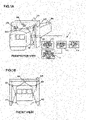
- FIGs. 1A and 1B illustrate an example of a configuration of the device for measuring the external shape of a railroad vehicle according to the first embodiment.
- the device includes a plurality of light section sensors 103 that irradiate linear laser beams 102 to a surface of a vehicle 101 and photograph the linear laser beams 102 (hereinafter referred to as light section lines) projected on the surface of the vehicle 101, a sensor rack 104 installing the plurality of light section sensors 103 to surround the vehicle on a rail, a vehicle moving distance measurement sensor 105 for measuring the moving distance of the vehicle from a reference position, and a measurement processing mechanism 110.
- the measurement processing mechanism 110 is configured of a laser intensity control unit 111 that changes the intensities of the linear laser beams 102 at predetermined time intervals, an image selection and shape calculation unit 112 that selects a light section line image of a laser beam intensity most suitable for the measurement position among from the photographed images of the light section line of the respective linear laser beams 102 with the intensities changed and calculates the external shape of the vehicle from the selected light section line image, an overall control unit 113 that performs control of respective equipment and that determines whether vehicle gauge has been exceeded, and a result output unit 114 that outputs the processing result of the overall control unit 113.
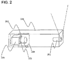
- the light section sensor 103 includes, as illustrated in FIG. 2 , a laser source unit 201 that irradiates the linear laser beams 102, and a photographing unit 202 that photographs the linear laser beam 102 projected on the surface of the vehicle 101.
- the photographing unit 202 is configured of a photographing camera 203, an imaging lens 204, and a narrow-band filter 205.
- the imaging lens 204 of the photographing camera 203 should be as wide-angled as possible to widen the field range of the respective light section sensors and cover the whole area of the outer periphery of the vehicle using a small number of light section sensors.
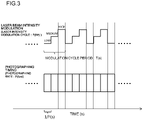
- the intensity of the linear laser beam 102 irradiated from the laser source unit 201 is changed in several steps by fixed frequencies: F (Hz) so as to synchronize with photographing rates: F (fps) of the photographing unit 202 by controlling applied voltage by the laser intensity control unit to the laser controller, as illustrated in FIG. 3 , and the laser source unit 201 is controlled to repeat this operation in laser intensity modulation cycle periods: T(s).
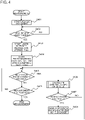
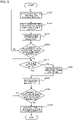
- the vehicle 101 starts moving from a rear side of the rack 104 toward the rack (step S401).
- step S402 moving distance of the vehicle 101 is monitored to determine whether the vehicle has reached a measurement start position set in advance (step S402), changing the intensity of the linear laser beams irradiated from the respective light section sensors in several steps for fixed frequencies: F(Hz) from the point in time when the vehicle has moved to the measurement start position set in advance (step S403), and photographing the light section lines successively by the photographing unit 202 using a preset photographing rate: F (fps) (step S404).
- F(Hz) fixed frequencies
- step S404 photographing the light section lines successively by the photographing unit 202 using a preset photographing rate: F (fps)
- the moving distance of the vehicle 101 is continuously monitored by the vehicle moving distance measurement sensor 105, and each time the vehicle moves for a predetermined distance (step S405), calculation of external shape of the vehicle based on the photographed light section lines (step S406) and determination on whether a vehicle gauge has been exceeded (whether all coordinate points of the external shape of the vehicle being measured is within a coordinate range indicating the vehicle gauge) are performed (step S407), wherein if the vehicle gauge has been exceeded, the points having exceeded the vehicle gauge are displayed (step S408).
- Steps S401 through S408 are repeated until it has been determined that the measurement position of the vehicle 101 has reached a measurement end position set in advance (step S409), and areas having exceeded the vehicle gauge are displayed for all measurement positions of the vehicle.
- N T ⁇ F based on the laser intensity modulation cycle period: T (s) and the photographing rate: F (fps).
- step SS501 detection of light section line pixels by detecting that the value of pixels has exceeded a threshold value in the respective photographed images having different measurement laser beam intensities (step SS501), calculation of mean pixel value: M [i] of pixels detected as light section lines in the respective photographed images and storage of calculated value to the memory are performed (step SS502), and a count value of number of processed images: i is updated (step SS503).
- step SS504 determination on whether the number of processed image has reached the single processing unit number is performed (step SS504), and if the number of processed images has reached the single processing unit number, detected mean pixel values: M [i] of the respective photographed images calculated in SS502 are compared, and the light section line having the highest mean value is selected.
- determination is performed on whether the mean pixel value of the detected pixels has not reached the saturation value of pixels and the value is the highest value (step SS), and if the determination condition of SS505 is satisfied, a maximum mean pixel value: M and image number where the mean pixel value becomes maximum: ks are updated (step SS506).
- step SS507 the number of compared images whose mean values are compared: k is updated (step SS507) to determine whether the number of compared images: k has reached the single processing unit number: N (step SS508), and calculation of external shape of the vehicle is performed using the light section line of the image number: ks having the highest detected mean pixel value at the point in time when the number of compared images: k has reached the number of single processing unit: N (step SS509).
- the calculation processing of external shape of the vehicle described above can also be performed after vehicle movement is completed.
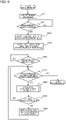
- steps S601 through S604 are the same as FIG. 4 , but in FIG. 6 , calculation of external shape of the vehicle is not performed while the vehicle is moving, and after determining that the vehicle has reached the measurement end position (step S605), the process of calculating the external shape of the vehicle (step S607) and the process of determining whether vehicle gauge has been exceeded (step S608) are performed until the processing of all measurement images has been completed (step S606), and as for the position determined to have exceeded the vehicle gauge is displayed, similar to FIG. 4 (step S609).
- the amount of reflected light of the laser beam for measurement is affected greatly by the paint color, but according to the first embodiment of the present invention, the laser beam intensity of light section line used for measurement can be selected, so that deterioration of shape accuracy caused by using an inappropriate laser intensity (too strong or too weak) with respect to the paint color of the vehicle can be reduced, and highly accurate shape measurement is enabled.
- FIGs. 7 and 8 The same configurations as the first embodiment are denoted with the same reference numbers and descriptions thereof are omitted.
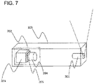
- the present second embodiment characterizes in that, as illustrated in FIG. 7 , a laser source unit 701 capable of generating multiple wavelengths corresponding to a wavelength range of respective pixels corresponding to RGB (red, green and blue) of a color camera is provided, and a color camera 702 is used as imaging camera.
- a laser source unit 701 capable of generating multiple wavelengths corresponding to a wavelength range of respective pixels corresponding to RGB (red, green and blue) of a color camera is provided, and a color camera 702 is used as imaging camera.
- SN ratio signal to noise ratio
- Lights of multiple wavelengths can be generated by preparing multiple laser devices of wavelengths respectively corresponding to R, G and B, or by using a laser having a wide wavelength range covering R, G and B.
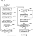
- the following describes a process for calculating the external shape of a vehicle based on the photographed light section lines (S406 of FIG. 4 , S607 of FIG. 6 ) with reference to a subroutine flowchart of calculation of external shape of vehicle illustrated in FIG. 8 .
- photographed images in which laser intensities are varied in multiple steps are repeatedly included in each laser intensity modulation cycle of the photographed images, so that processing is performed by setting images within the same laser intensity modulation cycle as a single processing unit.
- detection of light section line pixels is performed by detecting pixels whose pixel value has exceeded a threshold value set in advance in the respective photographed images of different measurement laser beam intensities, whereas in the present embodiment, light section lines of light having multiple wavelengths are photographed using color camera, so that respective photographed images having different measurement laser beam intensities are separated into RGB component images (step SS801).
- step SS802 the sum of pixel values of respective components of R, G and B are calculated (step SS802), and determination of threshold with respect to the sum of pixel values of selected RGB components is performed to detect light section line pixels (step SS803).
- M [i] of the sum of pixel values of pixels detected as light section lines and storage of the calculated value to the memory is performed (step SS804), and count value of the number of processed images: i is updated (step SS805), to determine whether the number of processed images has reached the single processing unit number (step SS806).
- the mean values of detected pixel values of respective photographed images calculated in SS804 are compared, and the light section line having the highest mean value is selected.
- the shape calculation accuracy is deteriorated if the pixel value of the light section line is saturated, so that whether the mean pixel value of the detected pixel has not reached the pixel saturation value and whether the value is the highest value is determined (step SS807), and if the determination condition of SS807 is satisfied, the maximum mean pixel value: M and the image number: ks where the mean pixel value becomes maximum are updated (step SS808).
- step SS809 the number of images having mean values compared: k is updated (step SS809), whether the number of compared images: k has reached the single processing unit number: N is determined (step SS810), and calculation of external shape of the vehicle is performed using the light section line of the image number: ks having the highest detected mean pixel value at the point in time when the number of compared images: k has reached the single processing unit number: N is performed (step SS811).
- FIGs. 9 through 13 Components that are the same as the first and second embodiments are denoted with the same reference numbers, and descriptions thereof are omitted.
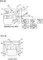
- FIGs. 9A and 9B illustrate one example of a configuration of a device for measuring the external shape of a railroad vehicle according to the present embodiment.
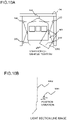
- a linear object 901 serving as a reference line is attached to cover both ends of the side surface of the railroad vehicle, and linear laser beams 102 are irradiated on the side surface of the linear object 901 serving as the reference line in addition to the side surface of vehicle, to thereby simultaneously detect a light section line 1002 of the side surface of the vehicle and a light section line 1003 of the linear object 901 illustrated in FIG. 10B in a field range 1001 of the light section sensor illustrated in FIG. 10A .
- amount of deviation of the vehicle from a reference position of rail is calculated based on position variation of the light section line 1003 caused by meandering of the vehicle, and correction of the calculated result in the image selection and shape calculation unit is performed by the calculated result.
- An object having ensured straightness in the order of submillimeter is preferable as the linear object 901 serving as the reference line, but since the whole length of the railroad vehicle is generally as long as approximately 20 meters, it is difficult to manufacture an object having an ensured straightness in the order of submillimeter to cover the whole length of the railroad vehicle.
- an example is described where an object such as a string (or cord) that is not meandered if tension is applied is used.
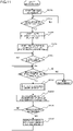
- FIG. 11 illustrates a flow of measurement of a case where the method for measuring external shape of railroad vehicle according to the third embodiment is performed.
- Steps S1101 through S1103 are the same as steps S401 through S403 of FIG. 4 , but during photographing of light section line in S1104, light section lines of the side surface of the vehicle and the linear object 901 are detected simultaneously, and after completing measurement, calculation and correction of the external shape of the vehicle and the amount of meandering of vehicle are performed.
- step S1108 illustrated in FIG. 11 the flow of the process for calculating and correcting the amount of meandering of vehicle based on the light selection line of the string being photographed (step S1108 illustrated in FIG. 11 ) will be described with reference to a subroutine flowchart of calculation and correction of amount of meandering of vehicle illustrated in FIG. 12 .
- photographed images in which laser intensities are varied in multiple steps are repeatedly included in each laser intensity modulation cycle of the photographed images, so that processing is performed by setting images within the same laser intensity modulation cycle as a single processing unit.
- the most preferable laser beam intensity can be determined in advance by using a string having the same color and quality across the whole length, the light selection line of the laser beam intensity determined in advance is selected from among the single process images (step SS1201), and light selection line of the string is detected by detecting the pixel having a pixel value that exceeds a threshold value set in advance (step SS1202), and thereafter, the processes of SS1201 and SS1202 are repeatedly performed for all designated photographed images (step SS1203).
- a linear position deviation along a direction perpendicular to the rail caused by the string not being positioned completely in parallel with the rail (inclination component of string) and vibration of the string caused by the movement of the vehicle (vibrational component of string) are superposed in the light section line data, so that it is necessary to remove the effect of these components on the light section line position of the string.
- the inclination component of the string is linear to the rail direction position, so data array of the light section line of the string detected in step SS1202 is converted into a rail coordinate system data array where the rail direction position and position perpendicular to the rail are set as coordinate axes (step SS1204), the linear component in the data array is calculated by fitting the linear expression to the data array, and removing the linear component (inclination component of string) from the data array (step SS1205).
- the vibration component of the string since the vibration component of the string includes a component that varies in fixed cycles, the data array of the light section line of the string after removing the linear component is converted into time data array in which the data sampling time and position in the direction perpendicular to the rail are set as coordinate axes (step SS1206), the vibrational component of the string is removed using a low pass filter capable of removing the vibration period of the string (step SS1207), and data array of light section line of the string having removed the inclination component of the string and the vibration component of the string (position variation data of string) is acquired.
- the data of light section line of the string is data acquired at fixed time intervals (intervals of laser intensity modulation cycle period) by determining the laser beam intensity in advance, so that the filtering process can be performed easily.
- period of vibration of the string can be expressed by expression (1) based on tension for stretching the string and the value of linear density of the string, and the actual vibration is a composition of a plurality of orders of modes, but by applying a low pass filter that removes frequencies greater than a primary mode having the lowest vibration frequency, vibration components of multiple modes can be removed.
- [Expression 1] fn n 2l s ⁇ [S: tension of string (N), p: linear density of string (kg/m), I: length of code (m), n: nth mode vibration]
- step SS1207 the position variation data array of the string in the perpendicular direction of the rail acquired in step SS1207 is added to or subtracted from external shape data of the vehicle acquired by light section sensors, by which the correction of error of external shape of the vehicle caused by meandering of the vehicle is performed (step SS1208).
- FIG. 13 has extracted a partial section of data from among the position variation data of the string acquired for the whole length of the vehicle.
- Data array 1301 of FIG. 13a illustrates a data array of the detected light section line of the string converted into a rail coordinate system in which the position in the rail direction and position in the direction perpendicular to the rail are set as coordinate axes
- data array 1302 of FIG. 13B illustrates a linear component (inclination component of string) acquired by fitting a linear expression to data array 1301 of FIG. 13A .
- Data array 1301 of FIG. 13C is acquired by removing the component of 1302 of FIG. 13B from 1301 of FIG. 13A
- data array1301 of FIG. 13E illustrating a position variation data array of the string caused by meandering of the vehicle can be acquired by removing 1303 of FIG. 13D corresponding to a vibration component of the string by applying a low pass filter to 1301 of FIG. 13C .
- laser beams for measuring the external shape of the vehicle is used to measure the amount of deviation of position of the linear object 901 simultaneously as measuring the side surface of the vehicle, the cross section of the side surface of vehicle being measured and the amount of positional deviation in the same cross section can be detected highly accurately, and the measurement accuracy of the external shape of the vehicle can be improved.
- a part of a configuration of a certain embodiment can be replaced with a configuration of other embodiments, or a configuration of a certain embodiment can be added to the configurations of other embodiments.
- a configuration of a certain embodiment can be added to, deleted from or replaced with configurations of other embodiments.
- 101 railroad vehicle 102 linear laser beam, 103 light section sensor, 104 sensor rack, 105 vehicle moving distance measurement sensor, 201 laser source unit, 202 photographing unit, 203 imaging camera, 204 imaging lens, 205 narrow-band filter, 701 multiple wavelength laser source unit, 702 color camera, 901 linear object, 1001 field range of light section sensor, 1002 light section line of side surface of vehicle, 1003 light section line of linear object, 1301 light section line data array of string in rail coordinate system, 1302 linear component of light section line data array of string in rail coordinate system, 1303 vibrational component of light section line data array of string in rail coordinate system.
Landscapes
- Physics & Mathematics (AREA)
- General Physics & Mathematics (AREA)
- Engineering & Computer Science (AREA)
- Computer Vision & Pattern Recognition (AREA)
- Length Measuring Devices By Optical Means (AREA)
Claims (10)
- Procédé de mesure d'une forme externe de véhicule ferroviaire en irradiant une pluralité de faisceaux laser linéaires (102) de façon continue sur une surface périphérique extérieure d'un véhicule ferroviaire (101) et en mesurant la forme externe du véhicule ferroviaire sur la base d'une position d'irradiation des faisceaux laser linéaires sur le véhicule ferroviaire et d'une image projetée sur un plan bidimensionnel des faisceaux laser linéaires irradiés sur la surface périphérique extérieure du véhicule ferroviaire, le procédé comprenant :une étape de photographie pour photographier une pluralité d'images de différentes intensités de faisceaux laser linéaires en commutant une intensité des faisceaux laser linéaires (102) lors de l'irradiation sur le véhicule ferroviaire (101),une étape de sélection pour sélectionner une image photographiée ayant une intensité de faisceaux laser la plus appropriée pour la position de mesure parmi une pluralité d'images ayant différentes intensités de faisceaux laser linéaires, dans lequel des valeurs de pixels d'une pluralité d'images ayant différentes intensités de faisceaux laser linéaires sont comparées, et une ligne de section de lumière ayant la valeur de pixels qui n'a pas atteint une valeur de saturation et qui a une valeur la plus élevée est sélectionnée, etune étape de calcul pour calculer la forme externe du véhicule ferroviaire (101) à partir de l'image photographiée sélectionnée.
- Procédé de mesure d'une forme externe de véhicule ferroviaire selon la revendication 1,
dans lequel le faisceau laser linéaire (102) comprend des plages de longueurs d'ondes multiples correspondant à des pixels RVB respectifs de l'image photographiée. - Procédé de mesure d'une forme externe de véhicule ferroviaire selon la revendication 1 ou la revendication 2, le procédé comprenant en outreune étape de détection de quantité d'écart pour détecter une quantité d'écart du véhicule ferroviaire (101) par rapport à une position de référence du rail à une position d'irradiation du faisceau laser linéaire (102) sur le véhicule ferroviaire, etune étape de correction de quantité d'écart pour corriger la quantité détectée d'écart du véhicule ferroviaire (101) par rapport à la position de référence du rail.
- Procédé de mesure d'une forme externe de véhicule ferroviaire selon la revendication 3,
dans lequel, à l'étape de détection de quantité d'écart, une ligne de section de lumière d'un objet linéaire (901) fixé aux deux extrémités du véhicule (101) et une surface latérale du véhicule sont détectées simultanément. - Procédé de mesure d'une forme externe de véhicule ferroviaire selon la revendication 4,
dans lequel, à l'étape de correction de quantité d'écart, une quantité de variation de position de la ligne de section de lumière de l'objet linéaire (901) dans un sens perpendiculaire au rail est calculée, et la quantité de variation de position est ajoutée aux ou soustraite des données de forme externe du véhicule (101). - Dispositif de mesure d'une forme externe de véhicule ferroviaire en irradiant une pluralité de faisceaux laser linéaires (102) de façon continue sur une surface périphérique extérieure d'un véhicule ferroviaire (101) et en mesurant la forme externe du véhicule ferroviaire sur la base d'une position d'irradiation des faisceaux laser linéaires sur le véhicule ferroviaire et d'une image projetée sur un plan bidimensionnel des faisceaux laser linéaires irradiés sur la surface périphérique extérieure du véhicule ferroviaire, le dispositif comprenant :un mécanisme (201) pour générer la pluralité de faisceaux laser linéaires (102), un mécanisme (105) pour spécifier une position d'irradiation sur le véhicule ferroviaire (101) sur lequel la pluralité de faisceaux laser linéaires doivent être irradiés, un mécanisme (111) pour irradier la pluralité de faisceaux laser linéaires avec des intensités des faisceaux laser linéaires commutées, un mécanisme (202) pour photographier des images de la pluralité de faisceaux laser linéaires irradiés sur la surface périphérique extérieure du véhicule ferroviaire, un mécanisme (112) pour sélectionner une image photographiée du faisceau laser linéaire le plus approprié pour une position de mesure parmi les images photographiées de la pluralité de faisceaux laser linéaires, et un mécanisme (113) pour calculer la forme externe du véhicule ferroviaire à partir de l'image photographiée sélectionnée du faisceau laser linéaire ;dans lequel le mécanisme (111) pour irradier la pluralité de faisceaux laser linéaires avec une intensité des faisceaux laser linéaires commutée irradie les faisceaux laser linéaires (102) sur la surface périphérique extérieure du véhicule ferroviaire (101) avec les intensités des faisceaux laser linéaires commutées,le mécanisme (202) pour photographier des images de la pluralité de faisceaux laser linéaires irradiés sur la surface périphérique extérieure du véhicule ferroviaire photographie une pluralité d'images de différentes intensités de faisceaux laser linéaires,le mécanisme (112) pour sélectionner l'image photographiée du faisceau laser linéaire le plus approprié pour la position de mesure sélectionne l'image photographiée ayant l'intensité de faisceaux laser la plus appropriée pour la position de mesure parmi la pluralité d'images entre lesquelles les intensités de la pluralité de faisceaux laser linéaires diffèrent, dans lequel il compare des valeurs de pixels d'une pluralité d'images ayant différentes intensités de faisceaux laser linéaires, et sélectionne une ligne de section de lumière dont la valeur de pixels n'a pas atteint une valeur de saturation et qui montre une valeur la plus élevée, etle mécanisme (113) pour calculer la forme externe du véhicule ferroviaire calcule la forme externe du véhicule ferroviaire (101) à partir de l'image photographiée sélectionnée.
- Dispositif de mesure d'une forme externe de véhicule ferroviaire selon la revendication 6,
dans lequel le faisceau laser linéaire (102) comprend des plages de longueurs d'ondes multiples correspondant à des pixels RVB respectifs de l'image photographiée. - Dispositif de mesure d'une forme externe de véhicule ferroviaire selon la revendication 6 ou la revendication 7,
comprenant en outre un mécanisme pour détecter une quantité d'écart du véhicule ferroviaire par rapport à une position de référence d'un rail du véhicule ferroviaire à la position d'irradiation sur laquelle le faisceau laser linéaire (102) est irradié sur le véhicule ferroviaire, et un mécanisme pour corriger la quantité détectée d'écart par rapport à la position de référence du rail du véhicule ferroviaire (101). - Dispositif de mesure d'une forme externe de véhicule ferroviaire selon la revendication 8,
dans lequel le mécanisme pour détecter la quantité d'écart du véhicule ferroviaire par rapport à la position de référence du rail comprend un objet linéaire (901) agencé sur les deux extrémités du véhicule ferroviaire, le mécanisme détectant simultanément une ligne de section de lumière de l'objet linéaire et la surface latérale du véhicule (101). - Dispositif de mesure d'une forme externe de véhicule ferroviaire selon la revendication 9,
dans lequel le mécanisme pour détecter la quantité d'écart du véhicule ferroviaire par rapport à la position de référence du rail calcule une quantité de variation de position de ligne de section de lumière de l'objet linéaire (901) dans un sens perpendiculaire au rail, et ajoute ou soustrait la quantité de variation de position aux ou des données de forme externe du véhicule (101).
Applications Claiming Priority (2)
| Application Number | Priority Date | Filing Date | Title |
|---|---|---|---|
| JP2016198011A JP6611691B2 (ja) | 2016-10-06 | 2016-10-06 | 鉄道車両の外形形状測定方法及び装置 |
| PCT/JP2017/030916 WO2018066270A1 (fr) | 2016-10-06 | 2017-08-29 | Procédé et dispositif de mesure de la forme externe d'un véhicule ferroviaire |
Publications (3)
| Publication Number | Publication Date |
|---|---|
| EP3524927A1 EP3524927A1 (fr) | 2019-08-14 |
| EP3524927A4 EP3524927A4 (fr) | 2020-06-17 |
| EP3524927B1 true EP3524927B1 (fr) | 2022-03-30 |
Family
ID=61831715
Family Applications (1)
| Application Number | Title | Priority Date | Filing Date |
|---|---|---|---|
| EP17858109.6A Active EP3524927B1 (fr) | 2016-10-06 | 2017-08-29 | Procédé et dispositif de mesure de la forme externe d'un véhicule ferroviaire |
Country Status (3)
| Country | Link |
|---|---|
| EP (1) | EP3524927B1 (fr) |
| JP (1) | JP6611691B2 (fr) |
| WO (1) | WO2018066270A1 (fr) |
Families Citing this family (3)
| Publication number | Priority date | Publication date | Assignee | Title |
|---|---|---|---|---|
| JP7227442B2 (ja) * | 2018-08-07 | 2023-02-22 | 株式会社日立製作所 | 車両寸法測定装置及び車両寸法測定方法 |
| EP3696537B1 (fr) * | 2019-02-15 | 2024-05-15 | SXT Retina Lab GmbH & Co. KG | Dispositif et procédé de détection des dommages sur un véhicule en déplacement |
| CN115305753B (zh) * | 2022-10-12 | 2023-02-07 | 中国铁建高新装备股份有限公司 | 一种钢轨廓形快速预测方法、系统 |
Family Cites Families (6)
| Publication number | Priority date | Publication date | Assignee | Title |
|---|---|---|---|---|
| EP1600351B1 (fr) * | 2004-04-01 | 2007-01-10 | Heuristics GmbH | Méthode et système pour la détection des défauts et des conditions périlleuses des véhicules ferroviaires passants |
| JP5228145B2 (ja) * | 2006-06-27 | 2013-07-03 | 東日本旅客鉄道株式会社 | 鉄道車両の出来形寸法の計測方法および計測システム、並びにその計測システムを具えた鉄道車両の出来形寸法検査システム |
| JP5631642B2 (ja) * | 2010-06-23 | 2014-11-26 | 株式会社日立ハイテクノロジーズ | 車両寸法測定方法及び装置 |
| JP5515039B2 (ja) * | 2010-10-22 | 2014-06-11 | 株式会社ミツトヨ | 画像測定装置 |
| US10368053B2 (en) * | 2012-11-14 | 2019-07-30 | Qualcomm Incorporated | Structured light active depth sensing systems combining multiple images to compensate for differences in reflectivity and/or absorption |
| JP6425586B2 (ja) * | 2015-03-04 | 2018-11-21 | 株式会社キーエンス | 光学式変位計測システム、撮像条件最適化方法および撮像条件最適化プログラム |
-
2016
- 2016-10-06 JP JP2016198011A patent/JP6611691B2/ja active Active
-
2017
- 2017-08-29 EP EP17858109.6A patent/EP3524927B1/fr active Active
- 2017-08-29 WO PCT/JP2017/030916 patent/WO2018066270A1/fr unknown
Also Published As
| Publication number | Publication date |
|---|---|
| WO2018066270A1 (fr) | 2018-04-12 |
| JP6611691B2 (ja) | 2019-11-27 |
| EP3524927A4 (fr) | 2020-06-17 |
| EP3524927A1 (fr) | 2019-08-14 |
| JP2018059835A (ja) | 2018-04-12 |
Similar Documents
| Publication | Publication Date | Title |
|---|---|---|
| EP3524927B1 (fr) | Procédé et dispositif de mesure de la forme externe d'un véhicule ferroviaire | |
| JP6888617B2 (ja) | 検査装置、検査方法 | |
| US6724491B2 (en) | Visual displacement sensor | |
| JP6382074B2 (ja) | 外観検査装置、外観検査システム、及び外観検査方法 | |
| US11494888B2 (en) | Work terminal, oil leakage detection apparatus, and oil leakage detection method | |
| US11025812B2 (en) | Imaging apparatus, imaging method, and imaging system | |
| JP2011121861A5 (fr) | ||
| JP2001201320A (ja) | 試験片の伸び測定方法及び装置 | |
| JP4939304B2 (ja) | 透明膜の膜厚測定方法およびその装置 | |
| US10473596B2 (en) | X-ray inspection apparatus | |
| CN113281343B (zh) | 一种对多层透明材料进行缺陷检测的系统及方法 | |
| JP5122729B2 (ja) | 3次元形状測定方法 | |
| KR101403860B1 (ko) | 웨이퍼표면 검사장치 및 이를 이용한 웨이퍼 표면 검사방법 | |
| WO2018008051A1 (fr) | Dispositif d'inspection et procédé d'inspection | |
| JP5057848B2 (ja) | 透明膜の屈折率測定方法およびその装置並びに透明膜の膜厚測定方法およびその装置 | |
| US9772259B2 (en) | Method for calibrating an X-ray testing system for a tire type and method for checking the position of cords in a tire | |
| JP6404985B1 (ja) | 距離画像の異常を検出する撮像装置 | |
| KR20160067303A (ko) | 실러 도포 품질 검사 장치 및 이를 이용한 실러 도포 품질 검사 방법 | |
| JP5214323B2 (ja) | 目視検査装置及び方法 | |
| JP2021081222A (ja) | 測定装置及び測定方法 | |
| KR101658221B1 (ko) | 전처리한 열화상 이미지를 이용한 실러 도포 품질 검사 장치 및 방법 | |
| KR20130107743A (ko) | 정밀 트리거 신호를 이용한 로봇 비젼 검사 시스템 및 그 방법 | |
| KR101492185B1 (ko) | 적설량 측정 장치 | |
| JP7013321B2 (ja) | 目視検査用の画像処理システム、及び、画像処理方法 | |
| JP2004093460A (ja) | レンズ検査方法 |
Legal Events
| Date | Code | Title | Description |
|---|---|---|---|
| STAA | Information on the status of an ep patent application or granted ep patent |
Free format text: STATUS: THE INTERNATIONAL PUBLICATION HAS BEEN MADE |
|
| PUAI | Public reference made under article 153(3) epc to a published international application that has entered the european phase |
Free format text: ORIGINAL CODE: 0009012 |
|
| STAA | Information on the status of an ep patent application or granted ep patent |
Free format text: STATUS: REQUEST FOR EXAMINATION WAS MADE |
|
| 17P | Request for examination filed |
Effective date: 20190327 |
|
| AK | Designated contracting states |
Kind code of ref document: A1 Designated state(s): AL AT BE BG CH CY CZ DE DK EE ES FI FR GB GR HR HU IE IS IT LI LT LU LV MC MK MT NL NO PL PT RO RS SE SI SK SM TR |
|
| AX | Request for extension of the european patent |
Extension state: BA ME |
|
| DAV | Request for validation of the european patent (deleted) | ||
| DAX | Request for extension of the european patent (deleted) | ||
| A4 | Supplementary search report drawn up and despatched |
Effective date: 20200520 |
|
| RIC1 | Information provided on ipc code assigned before grant |
Ipc: G01B 11/245 20060101ALI20200514BHEP Ipc: G01B 11/24 20060101AFI20200514BHEP Ipc: G01B 11/25 20060101ALI20200514BHEP |
|
| GRAP | Despatch of communication of intention to grant a patent |
Free format text: ORIGINAL CODE: EPIDOSNIGR1 |
|
| STAA | Information on the status of an ep patent application or granted ep patent |
Free format text: STATUS: GRANT OF PATENT IS INTENDED |
|
| INTG | Intention to grant announced |
Effective date: 20211020 |
|
| GRAS | Grant fee paid |
Free format text: ORIGINAL CODE: EPIDOSNIGR3 |
|
| GRAA | (expected) grant |
Free format text: ORIGINAL CODE: 0009210 |
|
| STAA | Information on the status of an ep patent application or granted ep patent |
Free format text: STATUS: THE PATENT HAS BEEN GRANTED |
|
| AK | Designated contracting states |
Kind code of ref document: B1 Designated state(s): AL AT BE BG CH CY CZ DE DK EE ES FI FR GB GR HR HU IE IS IT LI LT LU LV MC MK MT NL NO PL PT RO RS SE SI SK SM TR |
|
| REG | Reference to a national code |
Ref country code: GB Ref legal event code: FG4D |
|
| REG | Reference to a national code |
Ref country code: CH Ref legal event code: EP |
|
| REG | Reference to a national code |
Ref country code: DE Ref legal event code: R096 Ref document number: 602017055353 Country of ref document: DE |
|
| REG | Reference to a national code |
Ref country code: AT Ref legal event code: REF Ref document number: 1479571 Country of ref document: AT Kind code of ref document: T Effective date: 20220415 |
|
| REG | Reference to a national code |
Ref country code: IE Ref legal event code: FG4D |
|
| REG | Reference to a national code |
Ref country code: LT Ref legal event code: MG9D |
|
| PG25 | Lapsed in a contracting state [announced via postgrant information from national office to epo] |
Ref country code: SE Free format text: LAPSE BECAUSE OF FAILURE TO SUBMIT A TRANSLATION OF THE DESCRIPTION OR TO PAY THE FEE WITHIN THE PRESCRIBED TIME-LIMIT Effective date: 20220330 Ref country code: RS Free format text: LAPSE BECAUSE OF FAILURE TO SUBMIT A TRANSLATION OF THE DESCRIPTION OR TO PAY THE FEE WITHIN THE PRESCRIBED TIME-LIMIT Effective date: 20220330 Ref country code: NO Free format text: LAPSE BECAUSE OF FAILURE TO SUBMIT A TRANSLATION OF THE DESCRIPTION OR TO PAY THE FEE WITHIN THE PRESCRIBED TIME-LIMIT Effective date: 20220630 Ref country code: LT Free format text: LAPSE BECAUSE OF FAILURE TO SUBMIT A TRANSLATION OF THE DESCRIPTION OR TO PAY THE FEE WITHIN THE PRESCRIBED TIME-LIMIT Effective date: 20220330 Ref country code: HR Free format text: LAPSE BECAUSE OF FAILURE TO SUBMIT A TRANSLATION OF THE DESCRIPTION OR TO PAY THE FEE WITHIN THE PRESCRIBED TIME-LIMIT Effective date: 20220330 Ref country code: BG Free format text: LAPSE BECAUSE OF FAILURE TO SUBMIT A TRANSLATION OF THE DESCRIPTION OR TO PAY THE FEE WITHIN THE PRESCRIBED TIME-LIMIT Effective date: 20220630 |
|
| REG | Reference to a national code |
Ref country code: NL Ref legal event code: MP Effective date: 20220330 |
|
| REG | Reference to a national code |
Ref country code: AT Ref legal event code: MK05 Ref document number: 1479571 Country of ref document: AT Kind code of ref document: T Effective date: 20220330 |
|
| PG25 | Lapsed in a contracting state [announced via postgrant information from national office to epo] |
Ref country code: LV Free format text: LAPSE BECAUSE OF FAILURE TO SUBMIT A TRANSLATION OF THE DESCRIPTION OR TO PAY THE FEE WITHIN THE PRESCRIBED TIME-LIMIT Effective date: 20220330 Ref country code: GR Free format text: LAPSE BECAUSE OF FAILURE TO SUBMIT A TRANSLATION OF THE DESCRIPTION OR TO PAY THE FEE WITHIN THE PRESCRIBED TIME-LIMIT Effective date: 20220701 Ref country code: FI Free format text: LAPSE BECAUSE OF FAILURE TO SUBMIT A TRANSLATION OF THE DESCRIPTION OR TO PAY THE FEE WITHIN THE PRESCRIBED TIME-LIMIT Effective date: 20220330 |
|
| PG25 | Lapsed in a contracting state [announced via postgrant information from national office to epo] |
Ref country code: NL Free format text: LAPSE BECAUSE OF FAILURE TO SUBMIT A TRANSLATION OF THE DESCRIPTION OR TO PAY THE FEE WITHIN THE PRESCRIBED TIME-LIMIT Effective date: 20220330 |
|
| PG25 | Lapsed in a contracting state [announced via postgrant information from national office to epo] |
Ref country code: SM Free format text: LAPSE BECAUSE OF FAILURE TO SUBMIT A TRANSLATION OF THE DESCRIPTION OR TO PAY THE FEE WITHIN THE PRESCRIBED TIME-LIMIT Effective date: 20220330 Ref country code: SK Free format text: LAPSE BECAUSE OF FAILURE TO SUBMIT A TRANSLATION OF THE DESCRIPTION OR TO PAY THE FEE WITHIN THE PRESCRIBED TIME-LIMIT Effective date: 20220330 Ref country code: RO Free format text: LAPSE BECAUSE OF FAILURE TO SUBMIT A TRANSLATION OF THE DESCRIPTION OR TO PAY THE FEE WITHIN THE PRESCRIBED TIME-LIMIT Effective date: 20220330 Ref country code: PT Free format text: LAPSE BECAUSE OF FAILURE TO SUBMIT A TRANSLATION OF THE DESCRIPTION OR TO PAY THE FEE WITHIN THE PRESCRIBED TIME-LIMIT Effective date: 20220801 Ref country code: ES Free format text: LAPSE BECAUSE OF FAILURE TO SUBMIT A TRANSLATION OF THE DESCRIPTION OR TO PAY THE FEE WITHIN THE PRESCRIBED TIME-LIMIT Effective date: 20220330 Ref country code: EE Free format text: LAPSE BECAUSE OF FAILURE TO SUBMIT A TRANSLATION OF THE DESCRIPTION OR TO PAY THE FEE WITHIN THE PRESCRIBED TIME-LIMIT Effective date: 20220330 Ref country code: CZ Free format text: LAPSE BECAUSE OF FAILURE TO SUBMIT A TRANSLATION OF THE DESCRIPTION OR TO PAY THE FEE WITHIN THE PRESCRIBED TIME-LIMIT Effective date: 20220330 Ref country code: AT Free format text: LAPSE BECAUSE OF FAILURE TO SUBMIT A TRANSLATION OF THE DESCRIPTION OR TO PAY THE FEE WITHIN THE PRESCRIBED TIME-LIMIT Effective date: 20220330 |
|
| PG25 | Lapsed in a contracting state [announced via postgrant information from national office to epo] |
Ref country code: PL Free format text: LAPSE BECAUSE OF FAILURE TO SUBMIT A TRANSLATION OF THE DESCRIPTION OR TO PAY THE FEE WITHIN THE PRESCRIBED TIME-LIMIT Effective date: 20220330 Ref country code: IS Free format text: LAPSE BECAUSE OF FAILURE TO SUBMIT A TRANSLATION OF THE DESCRIPTION OR TO PAY THE FEE WITHIN THE PRESCRIBED TIME-LIMIT Effective date: 20220730 Ref country code: AL Free format text: LAPSE BECAUSE OF FAILURE TO SUBMIT A TRANSLATION OF THE DESCRIPTION OR TO PAY THE FEE WITHIN THE PRESCRIBED TIME-LIMIT Effective date: 20220330 |
|
| REG | Reference to a national code |
Ref country code: DE Ref legal event code: R097 Ref document number: 602017055353 Country of ref document: DE |
|
| PG25 | Lapsed in a contracting state [announced via postgrant information from national office to epo] |
Ref country code: DK Free format text: LAPSE BECAUSE OF FAILURE TO SUBMIT A TRANSLATION OF THE DESCRIPTION OR TO PAY THE FEE WITHIN THE PRESCRIBED TIME-LIMIT Effective date: 20220330 |
|
| PLBE | No opposition filed within time limit |
Free format text: ORIGINAL CODE: 0009261 |
|
| STAA | Information on the status of an ep patent application or granted ep patent |
Free format text: STATUS: NO OPPOSITION FILED WITHIN TIME LIMIT |
|
| REG | Reference to a national code |
Ref country code: DE Ref legal event code: R119 Ref document number: 602017055353 Country of ref document: DE |
|
| 26N | No opposition filed |
Effective date: 20230103 |
|
| PG25 | Lapsed in a contracting state [announced via postgrant information from national office to epo] |
Ref country code: MC Free format text: LAPSE BECAUSE OF FAILURE TO SUBMIT A TRANSLATION OF THE DESCRIPTION OR TO PAY THE FEE WITHIN THE PRESCRIBED TIME-LIMIT Effective date: 20220330 |
|
| REG | Reference to a national code |
Ref country code: CH Ref legal event code: PL |
|
| PG25 | Lapsed in a contracting state [announced via postgrant information from national office to epo] |
Ref country code: LU Free format text: LAPSE BECAUSE OF NON-PAYMENT OF DUE FEES Effective date: 20220829 Ref country code: LI Free format text: LAPSE BECAUSE OF NON-PAYMENT OF DUE FEES Effective date: 20220831 Ref country code: CH Free format text: LAPSE BECAUSE OF NON-PAYMENT OF DUE FEES Effective date: 20220831 |
|
| REG | Reference to a national code |
Ref country code: BE Ref legal event code: MM Effective date: 20220831 |
|
| PG25 | Lapsed in a contracting state [announced via postgrant information from national office to epo] |
Ref country code: SI Free format text: LAPSE BECAUSE OF FAILURE TO SUBMIT A TRANSLATION OF THE DESCRIPTION OR TO PAY THE FEE WITHIN THE PRESCRIBED TIME-LIMIT Effective date: 20220330 |
|
| PG25 | Lapsed in a contracting state [announced via postgrant information from national office to epo] |
Ref country code: IE Free format text: LAPSE BECAUSE OF NON-PAYMENT OF DUE FEES Effective date: 20220829 Ref country code: FR Free format text: LAPSE BECAUSE OF NON-PAYMENT OF DUE FEES Effective date: 20220831 Ref country code: DE Free format text: LAPSE BECAUSE OF NON-PAYMENT OF DUE FEES Effective date: 20230301 |
|
| PG25 | Lapsed in a contracting state [announced via postgrant information from national office to epo] |
Ref country code: BE Free format text: LAPSE BECAUSE OF NON-PAYMENT OF DUE FEES Effective date: 20220831 |
|
| PGFP | Annual fee paid to national office [announced via postgrant information from national office to epo] |
Ref country code: IT Payment date: 20230711 Year of fee payment: 7 Ref country code: GB Payment date: 20230706 Year of fee payment: 7 |
|
| PG25 | Lapsed in a contracting state [announced via postgrant information from national office to epo] |
Ref country code: HU Free format text: LAPSE BECAUSE OF FAILURE TO SUBMIT A TRANSLATION OF THE DESCRIPTION OR TO PAY THE FEE WITHIN THE PRESCRIBED TIME-LIMIT; INVALID AB INITIO Effective date: 20170829 |
|
| PG25 | Lapsed in a contracting state [announced via postgrant information from national office to epo] |
Ref country code: CY Free format text: LAPSE BECAUSE OF FAILURE TO SUBMIT A TRANSLATION OF THE DESCRIPTION OR TO PAY THE FEE WITHIN THE PRESCRIBED TIME-LIMIT Effective date: 20220330 |
|
| PG25 | Lapsed in a contracting state [announced via postgrant information from national office to epo] |
Ref country code: MK Free format text: LAPSE BECAUSE OF FAILURE TO SUBMIT A TRANSLATION OF THE DESCRIPTION OR TO PAY THE FEE WITHIN THE PRESCRIBED TIME-LIMIT Effective date: 20220330 |
|
| PG25 | Lapsed in a contracting state [announced via postgrant information from national office to epo] |
Ref country code: MT Free format text: LAPSE BECAUSE OF FAILURE TO SUBMIT A TRANSLATION OF THE DESCRIPTION OR TO PAY THE FEE WITHIN THE PRESCRIBED TIME-LIMIT Effective date: 20220330 |