EP3524910B1 - Heizkörper sowie verfahren zu dessen herstellung - Google Patents
Heizkörper sowie verfahren zu dessen herstellung Download PDFInfo
- Publication number
- EP3524910B1 EP3524910B1 EP19156417.8A EP19156417A EP3524910B1 EP 3524910 B1 EP3524910 B1 EP 3524910B1 EP 19156417 A EP19156417 A EP 19156417A EP 3524910 B1 EP3524910 B1 EP 3524910B1
- Authority
- EP
- European Patent Office
- Prior art keywords
- convector
- heating
- plates
- heating channel
- radiator
- Prior art date
- Legal status (The legal status is an assumption and is not a legal conclusion. Google has not performed a legal analysis and makes no representation as to the accuracy of the status listed.)
- Active
Links
Images




Classifications
-
- F—MECHANICAL ENGINEERING; LIGHTING; HEATING; WEAPONS; BLASTING
- F28—HEAT EXCHANGE IN GENERAL
- F28F—DETAILS OF HEAT-EXCHANGE AND HEAT-TRANSFER APPARATUS, OF GENERAL APPLICATION
- F28F1/00—Tubular elements; Assemblies of tubular elements
- F28F1/10—Tubular elements and assemblies thereof with means for increasing heat-transfer area, e.g. with fins, with projections, with recesses
- F28F1/12—Tubular elements and assemblies thereof with means for increasing heat-transfer area, e.g. with fins, with projections, with recesses the means being only outside the tubular element
- F28F1/126—Tubular elements and assemblies thereof with means for increasing heat-transfer area, e.g. with fins, with projections, with recesses the means being only outside the tubular element consisting of zig-zag shaped fins
- F28F1/128—Fins with openings, e.g. louvered fins
-
- F—MECHANICAL ENGINEERING; LIGHTING; HEATING; WEAPONS; BLASTING
- F28—HEAT EXCHANGE IN GENERAL
- F28D—HEAT-EXCHANGE APPARATUS, NOT PROVIDED FOR IN ANOTHER SUBCLASS, IN WHICH THE HEAT-EXCHANGE MEDIA DO NOT COME INTO DIRECT CONTACT
- F28D1/00—Heat-exchange apparatus having stationary conduit assemblies for one heat-exchange medium only, the media being in contact with different sides of the conduit wall, in which the other heat-exchange medium is a large body of fluid, e.g. domestic or motor car radiators
- F28D1/02—Heat-exchange apparatus having stationary conduit assemblies for one heat-exchange medium only, the media being in contact with different sides of the conduit wall, in which the other heat-exchange medium is a large body of fluid, e.g. domestic or motor car radiators with heat-exchange conduits immersed in the body of fluid
- F28D1/04—Heat-exchange apparatus having stationary conduit assemblies for one heat-exchange medium only, the media being in contact with different sides of the conduit wall, in which the other heat-exchange medium is a large body of fluid, e.g. domestic or motor car radiators with heat-exchange conduits immersed in the body of fluid with tubular conduits
- F28D1/053—Heat-exchange apparatus having stationary conduit assemblies for one heat-exchange medium only, the media being in contact with different sides of the conduit wall, in which the other heat-exchange medium is a large body of fluid, e.g. domestic or motor car radiators with heat-exchange conduits immersed in the body of fluid with tubular conduits the conduits being straight
- F28D1/0535—Heat-exchange apparatus having stationary conduit assemblies for one heat-exchange medium only, the media being in contact with different sides of the conduit wall, in which the other heat-exchange medium is a large body of fluid, e.g. domestic or motor car radiators with heat-exchange conduits immersed in the body of fluid with tubular conduits the conduits being straight the conduits having a non-circular cross-section
- F28D1/05366—Assemblies of conduits connected to common headers, e.g. core type radiators
-
- F—MECHANICAL ENGINEERING; LIGHTING; HEATING; WEAPONS; BLASTING
- F28—HEAT EXCHANGE IN GENERAL
- F28D—HEAT-EXCHANGE APPARATUS, NOT PROVIDED FOR IN ANOTHER SUBCLASS, IN WHICH THE HEAT-EXCHANGE MEDIA DO NOT COME INTO DIRECT CONTACT
- F28D21/00—Heat-exchange apparatus not covered by any of the groups F28D1/00 - F28D20/00
- F28D2021/0019—Other heat exchangers for particular applications; Heat exchange systems not otherwise provided for
- F28D2021/0035—Other heat exchangers for particular applications; Heat exchange systems not otherwise provided for for domestic or space heating, e.g. heating radiators
-
- F—MECHANICAL ENGINEERING; LIGHTING; HEATING; WEAPONS; BLASTING
- F28—HEAT EXCHANGE IN GENERAL
- F28F—DETAILS OF HEAT-EXCHANGE AND HEAT-TRANSFER APPARATUS, OF GENERAL APPLICATION
- F28F9/00—Casings; Header boxes; Auxiliary supports for elements; Auxiliary members within casings
- F28F9/02—Header boxes; End plates
- F28F2009/0285—Other particular headers or end plates
- F28F2009/0297—Side headers, e.g. for radiators having conduits laterally connected to common header
-
- F—MECHANICAL ENGINEERING; LIGHTING; HEATING; WEAPONS; BLASTING
- F28—HEAT EXCHANGE IN GENERAL
- F28F—DETAILS OF HEAT-EXCHANGE AND HEAT-TRANSFER APPARATUS, OF GENERAL APPLICATION
- F28F2225/00—Reinforcing means
- F28F2225/06—Reinforcing means for fins
Definitions
- the present application relates to a method for producing such a heater.
- a “collecting duct” is understood to mean a duct of the heating element which interacts in terms of flow with at least two other ducts.
- a collecting duct can interact with a large number of heating ducts, which are each connected to the collecting duct independently of one another.
- the heating ducts are connected to the collecting duct in a manner of speaking in a parallel circuit.
- heating duct is understood in the sense of the present application as a duct through which the heating medium can flow, the primary function of which is to release the thermal energy stored in the heating medium to the ambient air of the radiator. Consequently, there is typically an attempt to make an effective surface of a heating channel comparatively large, so that in particular a convective heat exchange with the ambient air can take place.
- a heating duct works together with a convector plate or some other device which is thermally connected to a wall of the heating duct and in this way drastically increases the surface area of the same.
- the heating channels can be incorporated, for example, in a heating plate, with the heating channels extending between two horizontally arranged collecting channels.
- the heating channels may have a different orientation, in particular a horizontal orientation.
- Tubular heating ducts are also conceivable, with flat tubes being used in particular in the case of so-called “heating walls", the width of which significantly exceeds their height.
- An “at least indirect connection” between a heating duct and at least one associated convector plate means both indirect and direct connections in the context of the present application.
- a convector plate is typically connected directly to a wall of a respectively associated heating duct, so that heat transfer from the heating duct to the convector plate is possible in a particularly efficient manner. Nevertheless, it is also conceivable that the convector plate interacts only indirectly with the heating duct with the interposition of a connecting component.
- individual convector plates are understood to mean convector plates that are separate from one another, at least in an assembled state in which they are not yet installed on the radiator. Furthermore, the convector plates can also be present separately and consequently independently of one another in a finished state of the radiator, in which they are connected in a force-transmitting manner to the heating duct. This mutually independent arrangement is then reflected in the fact that a direct transmission of forces from one convector plate to a respectively adjacent convector plate is not possible.
- the convector plates are initially present separately before being mounted on the heating duct, are mounted on the heating duct in this state and are then coupled to one another, so that a direct exchange of forces between adjacent convector plates is made possible.
- individual convector plates are not "in one piece” formed on a higher-level convector plate, as is known in the prior art. Instead, the convector plates continue to be “individually” within the meaning of the present application.
- the known radiators each comprise a convector plate which is provided with a large number of convector sections.
- a convector plate has a specific, repetitive shape, which is typically wavy or meandering, with each of the periodically repeating sections of the convector plate forming a convector section which, when mounted on the radiator, then together with the heating ducts forms a Convector channel forms.
- Convector sheets of this type are manufactured cyclically or continuously and cut to a specific length as required, so that the convector sheet can be connected to the heating ducts of the respective radiator.
- the convector plate is typically welded to the heating channels.
- the disadvantage of the known radiators is that it is not possible to influence the number of convector channels formed on the heating channels, since this is determined solely by the shape of the convector plate.
- this is of course not detrimental to the intended heat output of the respective radiator, the arrangement of a convector plate in the radiator is always accompanied by an increase in the weight of the radiator and additional costs for its manufacture.
- the Japanese patent application JP 2002-168 470A describes an air conditioner which is provided with a plurality of convector plates consisting of a base and two legs.
- the convector plates are arranged in a heat-transferring manner via the bases on a heating duct of the air conditioning system and are bent at the end sections facing away from the heating duct, which form the legs of the convector plates.
- the present invention was based on the object of further developing a known radiator with regard to the stability of the same.
- each of the convector plates has a Z-shape, with each convector plate having a single, flat base with which it is in contact with the heating duct, the at least a leg has at least one stiffener, preferably a plurality of stiffeners, which extends or extend in a vertical direction of the leg, wherein the at least one stiffener protrudes or protrudes from the leg to the base and in this way creates a kink between the base and the leg stiffen or stiffened.
- a “free end” is understood to mean an end of the convector plate that is not connected. In particular, there is no coupling of the convector plate to another object at this free end.
- the free end of the stiffening section is determined by that region of the stiffening section which faces away from the leg and is at the greatest distance from the leg.
- stiffening sections at the end of the convector plate facing away from the base leads in particular to improved stability of the same.
- the convector plates do not have a free end which extends in a direction away from the heating duct and is therefore freely accessible to a user.
- the introduction of stiffening sections thus causes also a reduced risk of injury.
- the stiffening sections are also particularly advantageous with regard to the optical design.
- the at least one leg of a respective convector plate is equipped with at least one reinforcement, preferably a plurality of reinforcements.
- These stiffeners extend in the vertical direction of the leg, preferably starting from the base.
- Such stiffening can be present in particular in the form of embossing, which is introduced into the convector plate when the material is cold.
- the convector plate has a kink in a transition area between the leg and the stiffening section, with an angle between the leg and the stiffening section in a range between 0° and 179°, preferably in a range between 10° and 120°.
- the leg and the stiffening section are arranged at an angle of approximately 90° to one another, in order to achieve a scale-like arrangement of the convector plates.
- a cross section of the stiffening section is formed in the shape of a circular arc.
- the transition between the leg and the stiffening section is softer.
- the distribution of the convector plates along the longitudinal axis of the heating duct can be both regular and irregular. In other words, a distribution is conceivable in which the distances between adjacent convector plates are consistently the same. Alternatively, however, it is also conceivable that a distance between at least two adjacent convector plates differs from the distance between at least two other adjacent convector plates. Furthermore, a distribution both in the longitudinal and in the transverse direction in relation to the longitudinal axis of the respective heating channel is conceivable. In other words, it can be advantageous to align the bases of the convector plates of a respective heating duct perpendicularly or parallel to the longitudinal axis of the heating duct. This depends primarily on the orientation of the heating channels themselves, it being understood that warm air performs an upward movement and the convector plates together form appropriately oriented channels through which the air can flow.
- the radiator according to the invention has many advantages. As can already be seen from the above description, there is a significant advantage in that the radiator can be equipped with any number of convector plates individually and in particular as required.
- the convector plates designed in the manner according to the invention each take up only a limited space on the associated heating duct, so that there is great freedom for the desired positioning of the convector plates.
- the convector plates can be arranged unevenly along the heating duct, whereby, for example, an increased concentration of convector plates can be made in a side area of the radiator, in which a convective heat exchange between the radiator and the environment is then also concentrated. It is also conceivable with vertically oriented heating channels, as they are typical with so-called "heating walls", that the convector plates are distributed differently over the height of the radiator, corresponding to a temperature distribution to be dissipated.
- At least one heating duct equipped with convector plates, preferably all heating ducts, and the associated convector plates are made of aluminum as such.
- Aluminum has particularly good heat-conducting properties with a low specific mass.
- such a heater can also be advantageous in which two different pairs of convector plates, each formed by two adjacent convector plates, have different distances between their convector plates. For example, it is conceivable that there is a distance of 3 cm between a first and a second convector plate and then a distance of 5 cm between the second and an adjoining third convector plate. It goes without saying that the distances between adjacent convector plates can be selected as desired, since the convector plates are present individually according to the invention and are connected to the heating duct independently of one another—and can therefore be positioned individually.
- a further particular advantage can result from a heater according to the invention, in which at least two heating ducts each have a large number of convector plates which are independent of one another.
- the advantage can be given by the fact that distances between adjacent convector plates on one heating duct differ from distances between adjacent convector plates on the other heating duct.
- different heating ducts can each be formed with a different number of convector plates, so that to a certain extent a “convector plate density” turns out to be different at different heating ducts.
- Such an embodiment can be useful, for example, when, due to the flow, different heating channels are flowed through with heating medium of different temperatures.
- the heating duct that is subjected to a higher temperature can provide a higher energy output and should therefore be provided with a higher density of convector plates.
- a heating duct through which comparatively cool heating medium flows can be provided with a smaller number of convector plates.
- At least one convector plate preferably all the convector plates, has only a single leg which extends from an edge of the base in the direction away from the heating duct.
- the leg extends relative to the base at an angle of between 80° and 90°, with an angle approaching 90° preferably an angle of exactly 90° being optimal.
- An orientation of the leg that deviates from a strictly vertical arrangement of the leg relative to the base has the particular advantage that an assembly tool, by means of which the base of the convector plate is connected to the heating duct in a force-transmitting manner, has additional space on the side of the base facing away from the heating duct is available because the leg deviates sideways to a certain extent.
- a material combination is advantageous in which a respective convector plate is made of aluminum and the heating duct is made of steel.
- the choice of aluminum for the convector sheets has the advantage of aluminum's particularly pronounced thermal conductivity properties and its low density. It goes without saying that other material combinations are of course also conceivable, in particular a construction of both the heating ducts and the convector plates each from aluminum.
- each individual convector plate is made particularly thin, in particular a thickness of less than 0.2 mm, preferably less than 0 ,1mm.
- a thickness of less than 0.2 mm is readily sufficient for the heat exchange function with the environment to be heated.
- the small thickness of the convector sheets can affect their stability.
- the reinforcement section has at least one bend, preferably a plurality of bends, at a free end.
- At least two convector plates of the heating duct are preferably arranged in such a way that they at least partially overlap, preferably are arranged completely next to each other.
- the arrangement of the convector plates parallel to the longitudinal axis on the heating duct is to be preferred, particularly in the case of vertically oriented heating ducts.
- the arrangement of several convector plates next to each other on the heating duct helps to significantly increase the convection surface created by the convector plates. Consequently, the convective heat exchange between the heating fluid and the air of the space to be heated can be increased.
- the underlying object is achieved according to the invention in that at least two adjacent convector plates, preferably a plurality of respectively adjacent convector plates, are connected to one another in a force-transmitting manner after they have been individually connected to a respective heating duct, in particular with the formation of a form fit.
- the convector plates are aligned relative to a mounting direction in such a way that the leg of a respective convector plate extends from an edge of the base facing the starting area of the heating duct.
- each convector plate to be connected to the heating duct is aligned prior to its connection to the heating duct in such a way that the leg faces the preceding convector plate already connected to the heating duct.
- the legs of the convector plates are aligned parallel to the longitudinal axis or parallel to the installation direction of the respective heating duct.
- the convector plates can be arranged individually on the respective heating channel in a particularly simple and automated manner.
- the leg of a respective convector plate is subject to a further movement of an assembly tool in the assembly direction itself not in the way. This applies both to the alignment of the convector plates parallel to the longitudinal axis and to the alignment perpendicular to the longitudinal axis. More can be seen particularly well from the exemplary embodiments below.
- convector plates of two pairs of convector plates are each arranged at different distances from one another. In this way, a higher concentration of convector plates can be set at certain points in the respective heating duct as required; a consistently uniform distribution of convector plates is not absolutely necessary according to the invention.
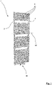
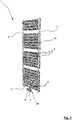
- a radiator 1 known in the prior art is shown, which is suitable, for example, for use with convector plates 8 .
- a heating element 1 comprises two connection cross-sections 2 , three collecting channels 3 , 4 and a large number of horizontally oriented heating channels 5 .
- the connection cross-sections 2 are arranged here together on a connection set 39 at a lower end of the radiator 1 and are used to connect the radiator 1 to a flow 6 and a return 7 of a heating system, not shown. It goes without saying that one of the connection cross-sections 2 can interact with the flow 6 and the other with the return 7 .
- the connection fitting 39 interacts with a lower, horizontally extending collecting channel 4 .
- This collecting duct 4 has a blocking element (not shown) in its middle region, which prevents the heating medium from directly overflowing from the flow 6 to the return 7 or a short circuit between the connection cross sections 2 .
- the collecting channel 4 is fluidically connected to a vertical collecting channel 3 in its section associated with the flow 6 .
- the heating medium provided via the flow 6 thus flows, starting from the flow 6 , into the lower collecting duct 4 and then into the vertical collecting duct 3 , in which it rises.
- the heating medium flows into the heating ducts 5 , which are each individually fluidically connected to the collecting duct 3 .
- the heating channels 5 are connected in parallel to a certain extent.
- the heating medium then flows through the individual heating channels 5 in the direction of an opposite collecting channel 3 which also extends vertically. In this collecting channel 3 flows the heating medium then back to the lower collecting channel 4 or its section associated with the return 7 .
- the heating medium is fed to the return line 7 and thus back to the heating system via the lower collecting channel 4 .
- the temperature of the heating medium is continuously reduced as it flows through the heating element 1 since the thermal energy of the heating medium is given off to the environment in particular by means of the heating channels 5 .
- the energy input into the environment takes place mainly by means of thermal radiation and convection.
- a heater 1 of this type—of course, but also any other conceivable heater—in one embodiment according to the invention comprises a multiplicity of convector plates 8 .
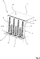
- a single convector sheet 8 is, for example, in figure 3 shown. It comprises a lower base 9 associated with a respective heating channel 5 , a leg 10 extending from the base 9 , and a stiffening portion 40 disposed at an upper end 17 of the leg applied to the base 9 .
- a longitudinal axis 37 of the base 9 is oriented here perpendicularly to a longitudinal axis 22 of the associated heating channel 5 or parallel to a width direction 38 of the heating channel 5 .
- the leg 10 extends from an edge 13 of the base, the convector plate 8 being provided with a kink 24 at the edge 13 .
- the leg 10 extends in a direction away from the heating channel 5 .
- the leg 10 and the base 9 together enclose an angle 14 which is approximately 80° here. The purpose of this design, which deviates from a vertical configuration of the angle 14 , becomes clear in connection with the following explanation figure 4 .
- the leg 10 has a kink 18 at an upper end 17 thereof.
- the stiffening section 40 of the convector plate 8 then extends from this upper end 17 , at the end of which facing away from the leg 10 the convector plate 8 has a free end 11 .
- the leg 10 and the stiffening section 40 together enclose an angle 41 which is approximately 90° here.
- the stiffening section 40 ensures that the leg 10 is not twisted relative to the base 9 unintentionally.
- the convector sheet 8 is formed from an aluminum sheet that has a thickness of approximately 0.1 mm.
- the heating channels 5 are made of steel.
- the convector plate 8 has a plurality of reinforcements 15 , 23 , which are the legs 10 are introduced.
- the reinforcements 15 , 23 extend parallel to a vertical direction 16 of the leg 10 .
- the reinforcements 23 protrude from the leg 10 to the base 9 and in this way reinforce the kink 24 between the base 9 and the leg 10 . This also ensures that the leg 10 does not twist unintentionally relative to the base 9 .
- the convector plate 8 formed in this way can be arranged on a heating duct 5 in a particularly simple manner.
- a connection is made here by means of ultrasonic welding, which in particular consists of figure 4 results.
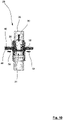
- the convector plate 8 according to figure 3 positioned with its base 9 on a respective heating channel 5 and then its base 9 is welded to the heating channel 5 at a total of two welding points 26 by means of a sonotrode 25 .
- a large number of convector plates 8 can be connected individually to the heating channel 5 without further ado.
- a linear weld seam is also conceivable, which can be produced with a disk-shaped or plate-shaped sonotrode.
- the technical purpose of the angle 14 of less than 90° now also arises: by means of the oblique orientation of the leg 10 relative to the base 9 , a free space facing the base 9 is created in which the sonotrode 25 finds sufficient space to connect of the convector plate 8 to be used with the heating channel 5 .
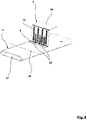
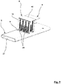
- a state of the convector plate 8 connected to the heating duct 5 can be seen particularly well from the perspective illustration according to FIG figure 5 .
- This representation shows that the convector plate 8 is welded to the heating duct 5 by means of two weld points 26 .
- the heating channel 5 is designed in the form of a flat tube, through the inner cavity 27 of which the heating medium can flow.
- the convector plate 8 Due to the direct connection of the convector plate 8 to the heating duct 5 , a particularly efficient heat transfer from the heating medium to the convector plate 8 and finally by convection to the environment to be heated can finally take place. If a sonotrode is used whose dimensions are small enough, an embodiment of the angle 14 of 90° is generally to be preferred.
- a further convector plate 8 is welded to the heating duct 5 in a subsequent processing step.
- another convector plate 8 is arranged on a side facing away from the leg 10 of the first convector plate 8 and then again connected to the heating channel 5 at two welding points 26 by means of the sonotrode 25 .
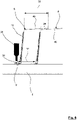
- the second convector sheet 8 positioned at a distance 12 from the first convector plate 8 . This distance 12 is selected to be smaller here than a length 33 of the stiffening section 40 of the convector plates 8 measured parallel to the longitudinal axis 22 of the heating duct 5 .
- the length 33 therefore exceeds the distance 12 , there is an overlapping area 28 in which the stiffening section 40 of the second convector plate 8 intersects with the stiffening section 40 of the first convector plate 8 .
- the convector plates 8 which are basically present individually, can be coupled to one another in a force-transmitting manner, in order to thus produce mutual reinforcement. This is explained separately below.
- the heating channel 5 can be provided with any number of convector plates 8 in the same way, with distances between adjacent convector plates 8 being freely selectable.
- the arrangement of the individual convector plates 8 takes place in a mounting direction that extends from a starting area 19 of the heating duct 5 in the direction of an opposite end area 20 .
- the assembly direction is therefore oriented parallel to the longitudinal axis 22 of the heating channel 5 .
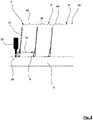
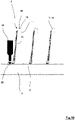
- the setting of a third convector plate 8 - again at a distance 12 to the preceding second convector plate 8 - is an example in figure 8 shown.
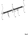
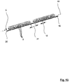
- FIG. 9 Such a finished heating channel 5 is shown in the illustration according to FIG figure 9 .
- adjacent convector plates 34 there is a distance 21 which clearly exceeds the distances 12 chosen between the convector plates 8 in other respects.
- two packs of convector plates 8 are formed on the heating duct 5 , so to speak.
- the distances between adjacent convector plates 8 can in principle be freely selected, since each convector plate 8 is set individually.
- a dedicated form-fitting point 31 is formed in the stiffening sections 40 .
- the cheeks 36 are moved laterally away from one another in the direction of the arrows 32 in order to give the material of the stiffening sections 40 room to deform.
- a modified type of convector plates 8 is used as an alternative to the convector plates 8 according to the above description, the stiffening sections 40 of which are not elongated in the same way, but are brought into a U-shape by means of a further kink 18 .
- This is particularly good based on the representation according to figure 11 recognizable.
- the different design of the stiffening section 40 means that adjacent convector plates 8 do not form an overlapping area 28 and consequently cannot be connected directly to one another.
- the introduction of the further kink 18 has the advantage that the respective convector plate 8 is additionally reinforced in the area of its stiffening section 40 .
- Heating ducts 5 which are also equipped with a plurality of convector plates 8 .
- the convector plates 8 are oriented parallel to the longitudinal axes 22 of the heating channels 5 here. Such an embodiment is particularly advantageous when the respective heating channel 5 is oriented vertically, so that a convective air flow can rise along the heating channel 5 .
- the individual convector plates 8 are arranged one behind the other along the heating channel 5 .
- An assembly of the convector plates 8 is comparable to the assembly of the convector plates 8 according to the above-described embodiments according to FIG Figures 1 to 13 away.
- the convector plates 8 are each connected individually to a wall of the heating duct 5 , in particular by means of ultrasonic welding at points or in a line.
- the sonotrode or sonotrodes move from convector plate 8 to convector plate 8 relative to the heating channel 5 parallel to its longitudinal axis 22 .
- convector plates 8 In principle, and independently of any other design of a heating element 1 according to the invention, it is conceivable to combine differently designed convector plates 8 on one and the same heating duct 5 . Furthermore, the formation of elongated convector plates 8 is conceivable, the length of which clearly exceeds the width of a heating channel 5 . Such convector plates 8 can extend perpendicularly to the longitudinal axis 22 of the respective heating duct 5 and thus bridge a free space between adjacent heating ducts 5 . In this way, the convector plates 8 can be connected to a plurality of heating ducts 5 arranged next to one another or one above the other. The advantage according to the invention of a free choice of distance between adjacent convector plates 8 remains unchanged as a result.
Landscapes
- Engineering & Computer Science (AREA)
- Physics & Mathematics (AREA)
- Thermal Sciences (AREA)
- Mechanical Engineering (AREA)
- General Engineering & Computer Science (AREA)
- Geometry (AREA)
- Domestic Hot-Water Supply Systems And Details Of Heating Systems (AREA)
Applications Claiming Priority (1)
| Application Number | Priority Date | Filing Date | Title |
|---|---|---|---|
| DE102018102950.0A DE102018102950A1 (de) | 2018-02-09 | 2018-02-09 | Heizkörper sowie Verfahren zu dessen Herstellung |
Publications (2)
| Publication Number | Publication Date |
|---|---|
| EP3524910A1 EP3524910A1 (de) | 2019-08-14 |
| EP3524910B1 true EP3524910B1 (de) | 2022-10-19 |
Family
ID=65408949
Family Applications (1)
| Application Number | Title | Priority Date | Filing Date |
|---|---|---|---|
| EP19156417.8A Active EP3524910B1 (de) | 2018-02-09 | 2019-02-11 | Heizkörper sowie verfahren zu dessen herstellung |
Country Status (3)
| Country | Link |
|---|---|
| EP (1) | EP3524910B1 (pl) |
| DE (1) | DE102018102950A1 (pl) |
| PL (1) | PL3524910T3 (pl) |
Families Citing this family (1)
| Publication number | Priority date | Publication date | Assignee | Title |
|---|---|---|---|---|
| CN117404953A (zh) * | 2023-11-01 | 2024-01-16 | 南京理工大学 | 一种仿生鲨鱼皮鳞百叶窗翅片散热器 |
Family Cites Families (10)
| Publication number | Priority date | Publication date | Assignee | Title |
|---|---|---|---|---|
| GB417573A (en) * | 1934-05-24 | 1934-10-08 | Aubrey Francis Snelling | Improvements in or relating to panel type radiators for heating buildings |
| CH409297A (de) * | 1963-09-19 | 1966-03-15 | Schlatter Ag | Radiator und Verfahren zur Herstellung desselben |
| BE793085A (fr) * | 1971-12-20 | 1973-04-16 | Rasmussen Gunnar O V | Convecteur pour le chauffage de batiments, compose de modules et outilset procede pour le fabriquer |
| FR2292206A1 (fr) * | 1974-11-20 | 1976-06-18 | Chausson Usines Sa | Echangeur de chaleur pour le chauffage par convection |
| DE3227146A1 (de) | 1982-07-21 | 1984-01-26 | Schäfer Werke GmbH, 5908 Neunkirchen | Waermetauscher, insbesondere plattenheizkoerper |
| JPH0221198A (ja) * | 1988-07-07 | 1990-01-24 | Nippon Denso Co Ltd | 熱交換器 |
| DE19921144B4 (de) | 1999-05-07 | 2010-06-02 | Caradon Heating Europe B.V. | Heizkörper |
| JP2002168470A (ja) * | 2000-11-30 | 2002-06-14 | Matsushita Electric Ind Co Ltd | 空気調和装置 |
| DE102009055177A1 (de) | 2009-12-22 | 2011-06-30 | Caradon Stelrad B.V. | Verfahren zur Herstellung eines Heizkörpers unter Verwendung eines Ultraschallschweißens sowie danach hergestellter Heizkörper |
| DE102012205916B4 (de) * | 2012-04-11 | 2018-09-06 | Mahle International Gmbh | Wellrippe |
-
2018
- 2018-02-09 DE DE102018102950.0A patent/DE102018102950A1/de not_active Withdrawn
-
2019
- 2019-02-11 EP EP19156417.8A patent/EP3524910B1/de active Active
- 2019-02-11 PL PL19156417.8T patent/PL3524910T3/pl unknown
Also Published As
| Publication number | Publication date |
|---|---|
| PL3524910T3 (pl) | 2023-01-30 |
| EP3524910A1 (de) | 2019-08-14 |
| DE102018102950A1 (de) | 2019-08-14 |
Similar Documents
| Publication | Publication Date | Title |
|---|---|---|
| DE102006057314B4 (de) | Wärmeaustauscher | |
| EP3062054B1 (de) | Wärmetauscher, insbesondere für ein kraftfahrzeug | |
| DE69910902T2 (de) | Unabhängig arbeitender und mobiler Heizkörper sowie Verfahren zu dessen Herstellung | |
| EP3499145B1 (de) | Anordnung einer vorrichtung zur temperierung eines raumes an einer decke des raumes | |
| DE102012023800A1 (de) | Wärmetauscherrohr, Wärmetauscherrohranordnung und Verfahren zum Herstellen desselben | |
| DE19958595A1 (de) | Verbindung für Wärmeaustauscherkern | |
| DE3131736A1 (de) | Verfahren zur herstellung von waermetauschern mit rundgebogenen teilen, sowie gemaess dem verfahren hergestellter waermetauscher | |
| DE102013008717A1 (de) | Flächenwärmetauscherelement, Verfahren zur Herstellung eines Flächenwärmetauscherelementes und Werkzeug | |
| EP2678615A1 (de) | Flachwärmetauscher | |
| EP0092033B1 (de) | Verfahren zur Herstellung eines Flachheizkörper | |
| EP2167895B1 (de) | Wärmetauscher | |
| DE202017102436U1 (de) | Wärmetauscher mit Mikrokanal-Struktur oder Flügelrohr-Struktur | |
| EP3524910A1 (de) | Heizkörper sowie verfahren zu dessen herstellung | |
| DE102018109517A1 (de) | Wärmetauschereinheit | |
| DE102012023801A1 (de) | Wärmetauscherrohr, Wärmetauscherrohranordnung und Verfahren zum Herstellen desselben | |
| DE102020000274A1 (de) | Verfahren zur Herstellung eines Rippen-Platten-Wärmetauschers | |
| DE112016002244B4 (de) | Wärmetauscher und Herstellungsverfahren hierfür | |
| DE102019123117A1 (de) | Flächenwärmetauscher, System und Verfahren | |
| DE102005002005B4 (de) | Kühlvorrichtung insbesondere für einen elektrischen Transformator | |
| EP0972998B1 (de) | Heiz- bzw. Kühlkörper-Verteileranordnung | |
| DE2720127A1 (de) | Waermeaustauscher sowie verfahren und werkzeug zu seiner herstellung | |
| DE2703632A1 (de) | Waermetauschrohr eines radiators fuer raumtemperierung | |
| DE3229757C2 (de) | Profilrohr für Wärmetauscher, insbesondere für Raumheizkörper | |
| DE3331619C2 (pl) | ||
| DE10232387A1 (de) | Absorber und Verfahren zu seiner Herstellung |
Legal Events
| Date | Code | Title | Description |
|---|---|---|---|
| PUAI | Public reference made under article 153(3) epc to a published international application that has entered the european phase |
Free format text: ORIGINAL CODE: 0009012 |
|
| STAA | Information on the status of an ep patent application or granted ep patent |
Free format text: STATUS: THE APPLICATION HAS BEEN PUBLISHED |
|
| AK | Designated contracting states |
Kind code of ref document: A1 Designated state(s): AL AT BE BG CH CY CZ DE DK EE ES FI FR GB GR HR HU IE IS IT LI LT LU LV MC MK MT NL NO PL PT RO RS SE SI SK SM TR |
|
| AX | Request for extension of the european patent |
Extension state: BA ME |
|
| STAA | Information on the status of an ep patent application or granted ep patent |
Free format text: STATUS: REQUEST FOR EXAMINATION WAS MADE |
|
| STAA | Information on the status of an ep patent application or granted ep patent |
Free format text: STATUS: EXAMINATION IS IN PROGRESS |
|
| 17P | Request for examination filed |
Effective date: 20200210 |
|
| RBV | Designated contracting states (corrected) |
Designated state(s): AL AT BE BG CH CY CZ DE DK EE ES FI FR GB GR HR HU IE IS IT LI LT LU LV MC MK MT NL NO PL PT RO RS SE SI SK SM TR |
|
| 17Q | First examination report despatched |
Effective date: 20200305 |
|
| GRAP | Despatch of communication of intention to grant a patent |
Free format text: ORIGINAL CODE: EPIDOSNIGR1 |
|
| STAA | Information on the status of an ep patent application or granted ep patent |
Free format text: STATUS: GRANT OF PATENT IS INTENDED |
|
| INTG | Intention to grant announced |
Effective date: 20220622 |
|
| GRAS | Grant fee paid |
Free format text: ORIGINAL CODE: EPIDOSNIGR3 |
|
| GRAA | (expected) grant |
Free format text: ORIGINAL CODE: 0009210 |
|
| STAA | Information on the status of an ep patent application or granted ep patent |
Free format text: STATUS: THE PATENT HAS BEEN GRANTED |
|
| AK | Designated contracting states |
Kind code of ref document: B1 Designated state(s): AL AT BE BG CH CY CZ DE DK EE ES FI FR GB GR HR HU IE IS IT LI LT LU LV MC MK MT NL NO PL PT RO RS SE SI SK SM TR |
|
| REG | Reference to a national code |
Ref country code: GB Ref legal event code: FG4D Free format text: NOT ENGLISH |
|
| REG | Reference to a national code |
Ref country code: CH Ref legal event code: EP |
|
| REG | Reference to a national code |
Ref country code: IE Ref legal event code: FG4D Free format text: LANGUAGE OF EP DOCUMENT: GERMAN |
|
| REG | Reference to a national code |
Ref country code: DE Ref legal event code: R096 Ref document number: 502019005942 Country of ref document: DE |
|
| REG | Reference to a national code |
Ref country code: AT Ref legal event code: REF Ref document number: 1525788 Country of ref document: AT Kind code of ref document: T Effective date: 20221115 |
|
| REG | Reference to a national code |
Ref country code: NL Ref legal event code: FP |
|
| REG | Reference to a national code |
Ref country code: LT Ref legal event code: MG9D |
|
| PG25 | Lapsed in a contracting state [announced via postgrant information from national office to epo] |
Ref country code: SE Free format text: LAPSE BECAUSE OF FAILURE TO SUBMIT A TRANSLATION OF THE DESCRIPTION OR TO PAY THE FEE WITHIN THE PRESCRIBED TIME-LIMIT Effective date: 20221019 Ref country code: PT Free format text: LAPSE BECAUSE OF FAILURE TO SUBMIT A TRANSLATION OF THE DESCRIPTION OR TO PAY THE FEE WITHIN THE PRESCRIBED TIME-LIMIT Effective date: 20230220 Ref country code: NO Free format text: LAPSE BECAUSE OF FAILURE TO SUBMIT A TRANSLATION OF THE DESCRIPTION OR TO PAY THE FEE WITHIN THE PRESCRIBED TIME-LIMIT Effective date: 20230119 Ref country code: LT Free format text: LAPSE BECAUSE OF FAILURE TO SUBMIT A TRANSLATION OF THE DESCRIPTION OR TO PAY THE FEE WITHIN THE PRESCRIBED TIME-LIMIT Effective date: 20221019 Ref country code: FI Free format text: LAPSE BECAUSE OF FAILURE TO SUBMIT A TRANSLATION OF THE DESCRIPTION OR TO PAY THE FEE WITHIN THE PRESCRIBED TIME-LIMIT Effective date: 20221019 Ref country code: ES Free format text: LAPSE BECAUSE OF FAILURE TO SUBMIT A TRANSLATION OF THE DESCRIPTION OR TO PAY THE FEE WITHIN THE PRESCRIBED TIME-LIMIT Effective date: 20221019 |
|
| PG25 | Lapsed in a contracting state [announced via postgrant information from national office to epo] |
Ref country code: RS Free format text: LAPSE BECAUSE OF FAILURE TO SUBMIT A TRANSLATION OF THE DESCRIPTION OR TO PAY THE FEE WITHIN THE PRESCRIBED TIME-LIMIT Effective date: 20221019 Ref country code: LV Free format text: LAPSE BECAUSE OF FAILURE TO SUBMIT A TRANSLATION OF THE DESCRIPTION OR TO PAY THE FEE WITHIN THE PRESCRIBED TIME-LIMIT Effective date: 20221019 Ref country code: IS Free format text: LAPSE BECAUSE OF FAILURE TO SUBMIT A TRANSLATION OF THE DESCRIPTION OR TO PAY THE FEE WITHIN THE PRESCRIBED TIME-LIMIT Effective date: 20230219 Ref country code: HR Free format text: LAPSE BECAUSE OF FAILURE TO SUBMIT A TRANSLATION OF THE DESCRIPTION OR TO PAY THE FEE WITHIN THE PRESCRIBED TIME-LIMIT Effective date: 20221019 Ref country code: GR Free format text: LAPSE BECAUSE OF FAILURE TO SUBMIT A TRANSLATION OF THE DESCRIPTION OR TO PAY THE FEE WITHIN THE PRESCRIBED TIME-LIMIT Effective date: 20230120 |
|
| P01 | Opt-out of the competence of the unified patent court (upc) registered |
Effective date: 20230521 |
|
| REG | Reference to a national code |
Ref country code: DE Ref legal event code: R097 Ref document number: 502019005942 Country of ref document: DE |
|
| PG25 | Lapsed in a contracting state [announced via postgrant information from national office to epo] |
Ref country code: SM Free format text: LAPSE BECAUSE OF FAILURE TO SUBMIT A TRANSLATION OF THE DESCRIPTION OR TO PAY THE FEE WITHIN THE PRESCRIBED TIME-LIMIT Effective date: 20221019 Ref country code: RO Free format text: LAPSE BECAUSE OF FAILURE TO SUBMIT A TRANSLATION OF THE DESCRIPTION OR TO PAY THE FEE WITHIN THE PRESCRIBED TIME-LIMIT Effective date: 20221019 Ref country code: EE Free format text: LAPSE BECAUSE OF FAILURE TO SUBMIT A TRANSLATION OF THE DESCRIPTION OR TO PAY THE FEE WITHIN THE PRESCRIBED TIME-LIMIT Effective date: 20221019 Ref country code: DK Free format text: LAPSE BECAUSE OF FAILURE TO SUBMIT A TRANSLATION OF THE DESCRIPTION OR TO PAY THE FEE WITHIN THE PRESCRIBED TIME-LIMIT Effective date: 20221019 Ref country code: CZ Free format text: LAPSE BECAUSE OF FAILURE TO SUBMIT A TRANSLATION OF THE DESCRIPTION OR TO PAY THE FEE WITHIN THE PRESCRIBED TIME-LIMIT Effective date: 20221019 |
|
| PLBE | No opposition filed within time limit |
Free format text: ORIGINAL CODE: 0009261 |
|
| STAA | Information on the status of an ep patent application or granted ep patent |
Free format text: STATUS: NO OPPOSITION FILED WITHIN TIME LIMIT |
|
| PG25 | Lapsed in a contracting state [announced via postgrant information from national office to epo] |
Ref country code: SK Free format text: LAPSE BECAUSE OF FAILURE TO SUBMIT A TRANSLATION OF THE DESCRIPTION OR TO PAY THE FEE WITHIN THE PRESCRIBED TIME-LIMIT Effective date: 20221019 Ref country code: AL Free format text: LAPSE BECAUSE OF FAILURE TO SUBMIT A TRANSLATION OF THE DESCRIPTION OR TO PAY THE FEE WITHIN THE PRESCRIBED TIME-LIMIT Effective date: 20221019 |
|
| 26N | No opposition filed |
Effective date: 20230720 |
|
| PG25 | Lapsed in a contracting state [announced via postgrant information from national office to epo] |
Ref country code: MC Free format text: LAPSE BECAUSE OF FAILURE TO SUBMIT A TRANSLATION OF THE DESCRIPTION OR TO PAY THE FEE WITHIN THE PRESCRIBED TIME-LIMIT Effective date: 20221019 |
|
| REG | Reference to a national code |
Ref country code: CH Ref legal event code: PL |
|
| PG25 | Lapsed in a contracting state [announced via postgrant information from national office to epo] |
Ref country code: LU Free format text: LAPSE BECAUSE OF NON-PAYMENT OF DUE FEES Effective date: 20230211 Ref country code: LI Free format text: LAPSE BECAUSE OF NON-PAYMENT OF DUE FEES Effective date: 20230228 Ref country code: CH Free format text: LAPSE BECAUSE OF NON-PAYMENT OF DUE FEES Effective date: 20230228 |
|
| PG25 | Lapsed in a contracting state [announced via postgrant information from national office to epo] |
Ref country code: SI Free format text: LAPSE BECAUSE OF FAILURE TO SUBMIT A TRANSLATION OF THE DESCRIPTION OR TO PAY THE FEE WITHIN THE PRESCRIBED TIME-LIMIT Effective date: 20221019 |
|
| REG | Reference to a national code |
Ref country code: IE Ref legal event code: MM4A |
|
| PG25 | Lapsed in a contracting state [announced via postgrant information from national office to epo] |
Ref country code: IE Free format text: LAPSE BECAUSE OF NON-PAYMENT OF DUE FEES Effective date: 20230211 |
|
| PG25 | Lapsed in a contracting state [announced via postgrant information from national office to epo] |
Ref country code: IT Free format text: LAPSE BECAUSE OF FAILURE TO SUBMIT A TRANSLATION OF THE DESCRIPTION OR TO PAY THE FEE WITHIN THE PRESCRIBED TIME-LIMIT Effective date: 20221019 |
|
| PG25 | Lapsed in a contracting state [announced via postgrant information from national office to epo] |
Ref country code: BG Free format text: LAPSE BECAUSE OF FAILURE TO SUBMIT A TRANSLATION OF THE DESCRIPTION OR TO PAY THE FEE WITHIN THE PRESCRIBED TIME-LIMIT Effective date: 20221019 |
|
| PG25 | Lapsed in a contracting state [announced via postgrant information from national office to epo] |
Ref country code: BG Free format text: LAPSE BECAUSE OF FAILURE TO SUBMIT A TRANSLATION OF THE DESCRIPTION OR TO PAY THE FEE WITHIN THE PRESCRIBED TIME-LIMIT Effective date: 20221019 |
|
| REG | Reference to a national code |
Ref country code: AT Ref legal event code: MM01 Ref document number: 1525788 Country of ref document: AT Kind code of ref document: T Effective date: 20240211 |
|
| PG25 | Lapsed in a contracting state [announced via postgrant information from national office to epo] |
Ref country code: AT Free format text: LAPSE BECAUSE OF NON-PAYMENT OF DUE FEES Effective date: 20240211 |
|
| PG25 | Lapsed in a contracting state [announced via postgrant information from national office to epo] |
Ref country code: CY Free format text: LAPSE BECAUSE OF FAILURE TO SUBMIT A TRANSLATION OF THE DESCRIPTION OR TO PAY THE FEE WITHIN THE PRESCRIBED TIME-LIMIT; INVALID AB INITIO Effective date: 20190211 |
|
| PG25 | Lapsed in a contracting state [announced via postgrant information from national office to epo] |
Ref country code: HU Free format text: LAPSE BECAUSE OF FAILURE TO SUBMIT A TRANSLATION OF THE DESCRIPTION OR TO PAY THE FEE WITHIN THE PRESCRIBED TIME-LIMIT; INVALID AB INITIO Effective date: 20190211 |
|
| PGFP | Annual fee paid to national office [announced via postgrant information from national office to epo] |
Ref country code: NL Payment date: 20260220 Year of fee payment: 8 |
|
| PGFP | Annual fee paid to national office [announced via postgrant information from national office to epo] |
Ref country code: GB Payment date: 20260122 Year of fee payment: 8 |
|
| PGFP | Annual fee paid to national office [announced via postgrant information from national office to epo] |
Ref country code: DE Payment date: 20260228 Year of fee payment: 8 |
|
| PGFP | Annual fee paid to national office [announced via postgrant information from national office to epo] |
Ref country code: AT Payment date: 20260410 Year of fee payment: 5 |
|
| PGFP | Annual fee paid to national office [announced via postgrant information from national office to epo] |
Ref country code: BE Payment date: 20260220 Year of fee payment: 8 |
|
| PGFP | Annual fee paid to national office [announced via postgrant information from national office to epo] |
Ref country code: FR Payment date: 20260227 Year of fee payment: 8 |
|
| PGFP | Annual fee paid to national office [announced via postgrant information from national office to epo] |
Ref country code: TR Payment date: 20260123 Year of fee payment: 8 |
|
| PGFP | Annual fee paid to national office [announced via postgrant information from national office to epo] |
Ref country code: PL Payment date: 20260116 Year of fee payment: 8 |