EP3524112A1 - Kupplungssystem zur verbindung zweier fluidleitungen - Google Patents
Kupplungssystem zur verbindung zweier fluidleitungen Download PDFInfo
- Publication number
- EP3524112A1 EP3524112A1 EP19153418.9A EP19153418A EP3524112A1 EP 3524112 A1 EP3524112 A1 EP 3524112A1 EP 19153418 A EP19153418 A EP 19153418A EP 3524112 A1 EP3524112 A1 EP 3524112A1
- Authority
- EP
- European Patent Office
- Prior art keywords
- sleeve
- coupling element
- wall
- coupling
- annular
- Prior art date
- Legal status (The legal status is an assumption and is not a legal conclusion. Google has not performed a legal analysis and makes no representation as to the accuracy of the status listed.)
- Granted
Links
Images

Classifications
-
- A—HUMAN NECESSITIES
- A47—FURNITURE; DOMESTIC ARTICLES OR APPLIANCES; COFFEE MILLS; SPICE MILLS; SUCTION CLEANERS IN GENERAL
- A47L—DOMESTIC WASHING OR CLEANING; SUCTION CLEANERS IN GENERAL
- A47L9/00—Details or accessories of suction cleaners, e.g. mechanical means for controlling the suction or for effecting pulsating action; Storing devices specially adapted to suction cleaners or parts thereof; Carrying-vehicles specially adapted for suction cleaners
- A47L9/24—Hoses or pipes; Hose or pipe couplings
- A47L9/242—Hose or pipe couplings
Definitions
- the invention relates to a coupling system for the fluid-tight connection of two fluid lines, in particular for connecting a handle and a hose of a vacuum cleaner.
- Vacuum cleaners have at different points coupling systems with which different air-bearing components of the vacuum cleaner can be connected together.
- the handle of a vacuum cleaner can be connected via a coupling system with a hose, can be passed through the intake air into a collecting space for dust.
- the connection of the hose to the handle is preferably carried out such that the hose can rotate relative to the handle to prevent twisting or torsion of the hose when using the vacuum cleaner.
- the connection of the hose should be formed as fluid-tight as possible in order to achieve the highest possible suction in an energy-efficient manner.
- US 4,941,689 A describes a coupling system with a sealing ring.
- DE 10 2009 048 379 A1 describes a vacuum cleaner with a seal for a ring channel.
- DE 10 2008 009 389 B3 describes a handle assembly on a suction hose.
- DE 10 2005 041 802 A1 describes a Saurrohran gleich.
- DE 2005 030 457 A1 describes a coupling system for a vacuum cleaner.
- the present document deals with the technical problem of providing a coupling system between two fluid lines, in particular between a handle and a hose of a nipple, suction device or vacuum cleaner, which efficiently and reliably both a sealed fluid-conducting connection between the fluid lines and a Rotational movement of the fluid lines allows each other.
- a coupling system for connecting two fluid lines can be used to connect two fluid lines of a vacuum cleaner or vacuum cleaner.
- a first fluid line can correspond to a handle of the nipple or vacuum cleaner.
- a second fluid line can correspond to a suction hose of the vacuum cleaner or vacuum cleaner.
- the components of the coupling system may be at least partially made of plastic.
- the fluid lines may be configured to carry suction air. In this case, the suction air sucked up by the sucker dust and / or absorbed by the sucker liquid with it.
- the coupling system comprises a first annular or tubular coupling element which is fixedly connected to the first fluid line or is connectable.
- the first coupling element can be designed as a common component with the first fluid line. This may in particular be the case with the handle of a vacuum cleaner or vacuum cleaner.
- the coupling system includes a second annular coupling element configured to enclose the second fluid line with a circular profile (e.g., the suction hose of a vacuum cleaner).
- a second annular coupling element configured to enclose the second fluid line with a circular profile (e.g., the suction hose of a vacuum cleaner).
- a circular profile e.g., the suction hose of a vacuum cleaner.
- the second coupling element can be pushed onto one end of the second fluid line.
- the coupling system comprises an annular sleeve which is fixedly connected to one end of the second fluid line.
- the sleeve can be glued or welded to the end of the second fluid line.
- the second coupling element eg a so-called click ring
- the Sleeve preferably formed such that the second coupling element is blocked by the attached sleeve, so that the second coupling element can no longer be withdrawn via the end to which the sleeve is attached, from the second fluid line.
- the sleeve may have an outer wall and an inner wall which extend in the axial direction and which may form an annular gap for receiving the end of the second fluid conduit.
- the end of the second fluid conduit may be clamped by the annular gap to form a strong connection between the sleeve and the second fluid conduit.
- the first coupling element and the second coupling element are connectable to each other such that in the connected state, the sleeve is rotatably supported by the first and second coupling element is enclosed, and that a fluid-conducting connection between the first coupling element and the sleeve is formed. Via the fluid-conducting connection, a fluid (in particular suction air) can then flow from the first fluid line, via the first coupling element, via the annular sleeve into the second fluid line.
- the fluid-conducting connection can thus be enclosed by a wall of the first coupling element and by the inner wall of the sleeve.
- the rotatable mounting of the sleeve allows rotation of the sleeve about the longitudinal axis of the sleeve.
- the outer wall of the sleeve is surrounded in the connected state in the radial direction by a system wall formed by the first and / or second coupling element.
- the first and second coupling element may be formed such that a nozzle (in particular a pipe socket) of the second coupling element (which is referred to in this document as a second nozzle) in a first nozzle (in particular a pipe socket) of the first coupling element can be introduced to connect the first and the second coupling element with each other.
- the surrounding the outer wall of the sleeve system wall can then be at least partially formed by an (outer) wall of the first coupling element.
- connection between the first and second coupling elements typically can not be made fluid tight in an efficient manner.
- transition between the first coupling element and the sleeve may typically not be made reliably fluid-tight, particularly as the sleeve is sandwiched between the two coupling elements to permit rotation of the sleeve about the longitudinal axis of the sleeve.
- the sleeve comprises an additional ring which is rotatably mounted on the outer wall of the sleeve.
- the auxiliary ring can enclose the outer wall of the sleeve.
- an annular, deformable seal is arranged on the additional ring, which is pressed in the connected state against the system wall in order to seal the fluid-conducting connection.
- the seal of the auxiliary ring and the friction surfaces may be formed such that the rotatable mounting of the sleeve is displaced away from the system wall to the friction surfaces.
- the rotational movement between the sleeve and the system wall substantially completely at the friction surfaces between the auxiliary ring and the sleeve done (and substantially not at all between the system wall and the seal of the additional ring).
- the friction surfaces can be efficiently sealed with relatively high quality, in particular because the friction surfaces are not separated during operation of the coupling system.
- the use of a deformable seal reliably and efficiently provides a high quality seal between the sleeve and the system wall.
- the outer wall of the sleeve may comprise an annular guide groove in which the auxiliary ring is rotatably arranged.
- the guide trough can be designed in an efficient manner as a (in the outer axis of the sleeve) circumferential recess in the outer wall.
- the guide groove may be formed to limit a movement of the additional ring in the axial direction (along the longitudinal axis of the sleeve).
- the additional ring may have an inner surface oriented toward the outer wall of the sleeve and an outer surface oriented toward the system wall. Furthermore, the additional ring may be limited in the axial direction by a first edge and by a second edge. The first edge and the second edge can thereby run in a circle around the outer wall of the sleeve. The first edge may be e.g. the first coupling element and the second edge may face the second coupling element.
- the auxiliary ring may have on or at least relatively close to the first edge on the inner surface an annular projection which projects outwardly from the inner surface towards the outer wall of the sleeve.
- the annular projection may be arranged closer to the first edge than at the second edge.
- the seal may be disposed on or relatively close to the second edge on the outer surface of the auxiliary ring. The seal can thus protrude out of the outer surface in the direction of the system wall.
- the seal can be arranged closer to the second edge than at the first edge.
- the outer wall of the sleeve and the inner surface of the auxiliary ring can form friction surfaces which allow rotation of the auxiliary ring about the longitudinal axis of the sleeve relative to the outer wall of the sleeve.
- the friction surfaces are preferably designed such that a coefficient of friction of the friction surfaces in contact for static friction and / or sliding friction is equal to or less than 0.5.
- the friction surfaces can each be relatively hard and / or each have a surface with a relatively low degree of roughness.
- the sleeve and / or the additional ring may have a certain diameter in the radial direction (eg 10 cm, 7 cm, 5 cm or less).
- the additional ring may have a width in the axial direction corresponding to 5%, 10%, 15% or more of the diameter of the sleeve and / or the additional ring.
- the additional ring can thus be considered relative be formed wide ring, so that the friction surfaces between the inner surface of the additional ring and the outer wall of the sleeve are relatively wide (along the longitudinal axis of the sleeve).
- a reliable rotational mobility and a high-quality sealing of the fluid-conducting connection can be effected.
- the gasket and the auxiliary ring can be manufactured in a cost-effective manner as a common multi, especially two, component part (for example by means of an injection molding process).
- a deformable material in particular an elastomer
- a not significantly deformable material in particular a thermoset or a thermoplastic, such as polyethylene (PE)
- PE polyethylene
- the seal on the auxiliary ring may comprise a material which is more deformable than the material of the additional ring, in particular as the material of the inner surface of the additional ring.
- the seal may include a plurality of annular resilient projections juxtaposed with respect to the axial direction of the sleeve to form a plurality of corresponding (annular) sealing locations on the system wall.
- the first coupling element and the second coupling element can be detachably connected to one another, in particular in order to be able to separate the first fluid line from the second fluid line (for example, to remedy a blockage in one of the fluid lines).
- the second socket of the second coupling element may comprise at least one unlocking button, which in the connected state in at least one corresponding opening of a wall of the first nozzle of the first Clutch element is engaged. By pressing on the one or more unlocking buttons, the one or more unlocking buttons can then be pushed out of the corresponding one or more openings to release the latch and so as to be able to pull the first socket of the first coupling element out of the second socket of the second coupling element.
- the sleeve is also typically released.
- first coupling element and the second coupling element in the axial and / or radial direction can be prevented to allow a stable and tight connection between the first and second fluid line.
- the first coupling element may comprise an annular projection surrounded by the wall of the first nozzle and, in the connected state, acting on an end surface of the sleeve to limit movement of the sleeve in the axial direction.
- the outer wall of the sleeve may have an annular projection which acts in the connected state on an end face of the second coupling element, in order to limit a movement of the sleeve in the axial direction.
- the outer wall of the sleeve may comprise an annular sleeve-neck, which is inserted in the connected state in an annular neck (in particular in the second neck) of the second coupling element.
- the (second) neck of the second coupling element may have an at least partially circumferential locking projection on a side facing the sleeve.
- the sleeve connection piece can have an at least partially encircling latching projection on a side facing the second coupling element.
- at least one of the locking projections is formed completely circumferentially.
- the two latching projections may be designed such that the two latching projections in the connected state allow a rotatable mounting of the sleeve on the second coupling element and that the two latching projections in the connected state counteract a movement of the sleeve in the axial direction relative to the second coupling element.
- the latching projections in the connected state, can counteract removal of the sleeve from the second coupling element. So can a comfortable and reliable separation or a comfortable and reliable construction of the connection between the two fluid lines are made possible. Furthermore, the reliability of the rotational movement and the tightness of the fluid-conducting connection can thus be increased.
- the diameter of the circumferential system wall (in particular the wall of the first neck of the first coupling element) can be reduced in the axial direction away from the sleeve. Such reduction in diameter may cause the pressure from the system wall to increase on the seal as the sleeve is urged axially toward the first coupling member. Furthermore, due to the reducing diameter at the point of contact between the seal and the system wall, the system wall is inclined to the seal or to the longitudinal axis of the sleeve, which can lead to an increase in the contact area. Overall, so the tightness of the fluid-conducting connection can be further increased.
- a sucker or a suction device in particular a vacuum cleaner, which comprises a handle designed as a first fluid line and a suction hose designed as a second fluid line.
- the suction device or the suction device comprises the coupling system described in this document, which is designed to connect the first fluid line and the second fluid line essentially fluid-tightly (in particular gas-tight) such that the second fluid line during operation of the suction device or suction device can be rotated relative to the first fluid line.
- a comfortable and energy-efficient vacuum cleaner in particular vacuum cleaner, can be provided.
- a coupling system which reliably and efficiently permits a rotatable and fluid-tight connection between two fluid conduits, in particular between a suction hose and the connector to a suction pipe of a vacuum cleaner.
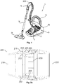
- FIG. 1 an exemplary vacuum cleaner 4.
- vacuum cleaner 4 is sucked by the designed as a floor nozzle 25 dust collecting device by a suction air 5 consisting of a length adjustable suction pipe 15, a connector 14 and a flexible suction hose 16 in the vacuum cleaner 4 by a motor-blower unit 8.
- a Staubabscheideisme 6 in the housing 26 of the vacuum cleaner 4 separates the dust contained in the intake air into a collecting space 7.
- the connecting piece 14 can be designed as a handle.
- the connecting piece 14 (also referred to below as a handle) is typically connected to the suction hose 16 via a coupling system 200.
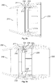
- the FIGS. 2a and 2 B show an exemplary coupling system 200, with a handle side (first) coupling element 210 and a hose side (second) coupling element 220.
- the handle side coupling element 210 may be formed by one end of the tubular handle 14.
- the hose-side coupling element 220 may be formed as a ring which can be pushed onto the outside of the hose 16.
- the hose-side coupling member 220 may be more typically moved relative to the hose 16, in particular rotated.
- the handle-side coupling element 210 is typically fixedly connected to the handle 14.
- the hose-side coupling element 220 may be designed to be inserted into the handle-side coupling element 210.
- the handle-side coupling element 210 may have one or more openings 511 in the wall 211 and the hose-side coupling element 220 one or more unlocking buttons 521 on the wall, so that in the mated state, the one or more unlocking buttons 521 project into the one or more openings 511 and thus cause a rigid connection between the two coupling elements 210, 220 (see Fig. 5a ).
- the coupling system 200 further includes a sleeve 230, which is connected to the end of the tube 16, in particular glued, can be. It may thus be a fluid-tight and rigid connection between sleeve 230 and hose 16. Furthermore, the sleeve 230 and the hose-side coupling element 220 may be formed such that a connection can be made between the sleeve 230 and the hose-side coupling element 220 which, on the one hand, permits a rotation between the sleeve 230 and the hose-side coupling element 220, but which, on the other hand, causes relative movement axial direction (relative to the longitudinal direction of the tube 16 and the sleeve 230) is prevented.
- the sleeve 230 for this purpose may have a circumferential around the hose 16 locking projection 235 which engages with a circumferential locking cam 225 of the hose-side coupling element 220 (or vice versa).
- the sleeve 230 and the hose 16 connected therewith can be rotated relative to the hose-side coupling element 220, but on the other hand the sleeve 230 and the hose 16 connected therewith can only be displaced from the one in the axial direction by overcoming a predefined pulling force in the axial direction hose-side coupling element 220 can be separated.
- the sleeve 230 (firmly connected to the hose 16) and the hose-side coupling element 220 (enclosing the outside of the hose 16) can be connected to the handle-side coupling element 210.
- the sleeve 230 and the hose-side coupling element 220 can be inserted at least partially into the end of the handle-side coupling element 210.
- the handle-side coupling element 210 may have on an inner side of the wall 211 a circumferential projection 212 which is formed such that in the connected state, an annular end face 232 of the sleeve 230 is pressed against the projection 212.
- the contact pressure of the sleeve 230 is preferably so low that, furthermore, during normal operation of the vacuum cleaner 4, a rotation is made possible between the handle-side coupling element 210 and the sleeve 230 or the hose 16.
- the sleeve 230 may have on the outside of the outer wall of the sleeve 230 (eg between the end face 232 and the locking projection 235 to the hose side coupling member 220) an annular sealing member 231 which is pressed against the inside of the wall 211 of the handle side coupling member 210 to the sleeve 230 or to seal the tube 16 to the handle-side coupling element 210 out.
- the sealing member 231 is typically formed of the hard material (e.g., a thermoset, such as polyethylene (PE)) of the sleeve 230 to permit relative rotational movement between the handle side coupling member 210 and the sleeve 230.
- PE polyethylene
- a hard seal 231 integrally formed on the adhesive sleeve 230 can be used to seal the handle 14 of a vacuum cleaner 4 against the inner surface of the handle 14.
- the seal 231 rotates on the inner surface of the handle 14 and thus allows a rotational mobility of the tube 16 relative to the handle 14. Due to the rigidity of the molded seal 231 and due to the manufacturing tolerances and / or the irregularities on the handle 14, however, a complete tightness is typically not effected become.
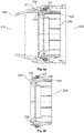
- FIGS. 3a . 3b 4a, 4b show sleeves 230, which allow an increased degree of tightness and also a good rotational mobility.
- the sleeve 230 faces this Purpose an additional ring 332 which is arranged on the outside of the wall 33 of the sleeve 230, that the auxiliary ring 332 can be rotated relative to the wall 333 of the sleeve 230.
- the wall 333 of the sleeve 230 may have an annular guide groove 336 for the auxiliary ring 332, so that the auxiliary ring 332 can be rotated within the guide groove 336 or guide track about the longitudinal axis of the sleeve 230 and thereby guided by the edges of the guide groove 336.
- a deformable, annular seal 331 may be attached.
- the seal 331 and the auxiliary ring 332 may be formed such that the deformable seal 331 is pressed in the connected state of the coupling system 200 against the inside of the wall 211 of the handle-side coupling element 210.
- a good seal between the deformable seal 331 and the inside of the wall 211 can be effected.
- tolerances and / or non-circularity of the wall 211 can be compensated by the deformable seal 331.
- the additional ring 332 is pressed against the (outer) wall 333 of the sleeve 230, so that a good seal at the transition between the additional ring 332 and wall 333 of the sleeve 230 can be effected.
- the additional ring 332 may have a relatively large width in the axial direction of the sleeve 230, wherein with increasing width of the additional ring 332, the sealing effect can be further increased.
- the provision of a guide groove or depression 336 for guiding the additional ring 332 can contribute to increasing the sealing effect.
- the additional ring 332 and the wall 333 of the sleeve 230 are preferably formed hard (for example, each made of a thermoset or a thermoplastic, such as polyethylene (PE)), continues to be a reliable and smooth rotational movement between the additional ring 332 and sleeve 230 allows.
- PE polyethylene
- auxiliary ring 332 and the seal 331 can be made, for example, as a two-component part.
- the seal 331 is fixed during operation of a vacuum cleaner 4 and does not rotate or not substantially on the inner surface of the wall 211 of the handle 14.
- the deformable seal 331 compensates for the tolerances and non-circularity of the handle 14.
- the adhesive sleeve 230 and the auxiliary ring 332 can typically have a more accurate diameter tolerance and a more accurate Roundness are made as the handle 14, so that the contact point between the adhesive sleeve 230 and additional ring 332 can be better sealed and with increased efficiency.
- the additional ring 332 with the molded soft seal 331 thus takes over the sealing of the tube 16 to the handle 14.
- the geometry of the seal 331 can be designed differently, for example, round, oval, trapezoidal, triangular, diamond-shaped, lug-shaped, etc., to the highest possible Degree of tightness effect.
- the auxiliary ring 332 may have an annular projection 334 at a first edge 341 and at an inner surface 338.
- the seal 331 may, as in Fig. 3c may be arranged on an opposite second edge 342 on the outer surface 339 of the additional ring 332.
- a holding rib or a projection 335 can be formed on the adhesive sleeve 230, which limits or prevents a displacement of the additional ring 332 in the axial direction. Furthermore, an additional sealing effect at the transition between adhesive sleeve 230 and additional ring 332 can be effected by the retaining rib 335.
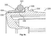
- the seal 331 may, as in Fig. 3c represented, applied to the additional ring 332, and / or as in Fig. 4c shown embedded in the auxiliary ring 332.
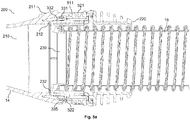
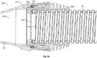
- FIGS. 5a and 5b show the coupling system 200 with a hose 16 which is fixedly connected to the sleeve 230.
- the coupling system 200 described in this document allows a reliable and robust sealing of a fluid-conducting connection between a Handle 14 and a suction hose 16 of a vacuum cleaner 4.
- the coupling system 200 is adapted to compensate for relatively large variations in the shape of a handle 14.
- handles 14 can be produced with a relatively large manufacturing tolerance and thus cost.
- the coupling system 200 described unpleasant hissing or whistling during operation of a vacuum cleaner 4 (in particular when pulling and / or buckling of the suction hose 16) can be avoided.
- the described coupling system 200 the energy efficiency and / or the absorbency of a vacuum cleaner 4 can be increased.
Landscapes
- Engineering & Computer Science (AREA)
- Mechanical Engineering (AREA)
- Quick-Acting Or Multi-Walled Pipe Joints (AREA)
Abstract
Description
- Die Erfindung betrifft ein Kupplungssystem zur fluiddichten Verbindung zweier Fluidleitungen, insbesondere zur Verbindung eines Handgriffs und eines Schlauchs eines Staubsaugers.
- Staubsauger weisen an unterschiedlichen Stellen Kupplungssysteme auf, mit denen unterschiedliche luftführende Komponenten des Staubsaugers miteinander verbunden werden können. Insbesondere kann der Handgriff eines Staubsaugers über ein Kupplungssystem mit einem Schlauch verbunden werden, durch den Ansaugluft in einen Sammelraum für Staub geführt werden kann. Die Anbindung des Schlauchs an den Handgriff erfolgt dabei bevorzugt derart, dass sich der Schlauch gegenüber dem Handgriff drehen kann, um ein Verdrehen bzw. eine Torsion des Schlauchs bei der Nutzung des Staubsaugers zu verhindern. Des Weiteren sollte die Anbindung des Schlauchs möglichst fluiddicht ausgebildet sein, um in energieeffizienter Weise eine möglichst hohe Saugwirkung zu erzielen.
-
US 4 941 689 A beschreibt ein Kupplungssystem mit einem Dichtungsring.DE 10 2009 048 379 A1 beschreibt einen Staubsauger mit einer Abdichtung für einen Ringkanal.DE 10 2008 009 389 B3 beschreibt eine Griffanordnung an einem Saugschlauch.DE 10 2005 041 802 A1 beschreibt eine Saurrohranschlusseinheit.DE 2005 030 457 A1 beschreibt ein Kupplungssystem für einen Staubsauger. - Das vorliegende Dokument befasst sich mit der technischen Aufgabe, ein Kupplungssystem zwischen zwei Fluidleitungen, insbesondere zwischen einem Handgriff und einem Schlauch eines Saugers, Sauggeräts bzw. Staubsaugers, bereitzustellen, das in effizienter und zuverlässiger Weise sowohl eine abgedichtete fluidleitende Verbindung zwischen den Fluidleitungen als auch eine Rotationsbewegung der Fluidleitungen zueinander ermöglicht.
- Die Aufgabe wird durch den Gegenstand des unabhängigen Patentanspruchs gelöst. Vorteilhafte Ausführungsformen sind insbesondere in den abhängigen Patentansprüchen definiert, in nachfolgender Beschreibung beschrieben oder in der beigefügten Zeichnung dargestellt.
- Gemäß einem Aspekt der Erfindung wird ein Kupplungssystem zur Verbindung zweier Fluidleitungen beschrieben. Das Kupplungssystem kann zur Verbindung zweier Fluidleitungen eines Saugers bzw. Staubsaugers verwendet werden. Dabei kann eine erste Fluidleitung einem Handgriff des Saugers bzw. Staubsaugers entsprechen. Des Weiteren kann eine zweite Fluidleitung einem Saugschlauch des Saugers bzw. Staubsaugers entsprechen. Die Komponenten des Kupplungssystems können zumindest teilweise aus Kunststoff hergestellt sein. Die Fluidleitungen können eingerichtet sein, Saugluft zu führen. Dabei kann die Saugluft von dem Sauger aufgesaugten Staub und/oder von dem Sauger aufgesaugte Flüssigkeit mit sich führen.
- Das Kupplungssystem umfasst ein erstes ring- oder rohrförmiges Kupplungselement, das fest mit der ersten Fluidleitung verbunden ist oder verbindbar ist. Insbesondere kann das erste Kupplungselement als gemeinsames Bauteil mit der ersten Fluidleitung ausgebildet sein. Dies kann insbesondere bei dem Handgriff eines Saugers bzw. Staubsaugers der Fall sein.
- Außerdem umfasst das Kupplungssystem ein zweites ringförmiges Kupplungselement, das ausgebildet ist, die zweite Fluidleitung mit einem kreisförmigen Profil (z.B. den Saugschlauch eines Saugers bzw. Staubsaugers) zu umschließen. Dabei besteht typischerweise keine mechanisch feste Verbindung zwischen dem zweiten Kupplungselement und der zweiten Fluidleitung, um es zu ermöglichen, dass das zweite Kupplungselement und die zweite Fluidleitung relativ zueinander verdreht werden können. Beispielsweise kann das zweite Kupplungselement auf ein Ende der zweiten Fluidleitung aufgeschoben werden.
- Ferner umfasst das Kupplungssystem eine ringförmige Hülse, die fest mit einem Ende der zweiten Fluidleitung verbindbar ist. Beispielsweise kann die Hülse mit dem Ende der zweiten Fluidleitung verklebt oder verschweißt werden. Dabei kann zunächst das zweite Kupplungselement von dem Ende her auf die zweite Fluidleitung geschoben werden. Anschließend kann die Hülse fest mit dem Ende der zweiten Fluidleitung verbunden werden. Dabei sind das zweite Kupplungselement (z.B. ein sogenannter Klickring) und die Hülse bevorzugt derart ausgebildet, dass das zweite Kupplungselement durch die befestigte Hülse blockiert wird, so dass das zweite Kupplungselement nicht mehr über das Ende, an dem die Hülse befestigt ist, von der zweiten Fluidleitung abgezogen werden kann.
- Die Hülse kann eine Außenwand und eine Innenwand aufweisen, die sich in axialer Richtung erstrecken und die einen ringförmigen Spalt zur Aufnahme des Endes der zweiten Fluidleitung bilden können. Das Ende der zweiten Fluidleitung kann durch den ringförmigen Spalt eingeklemmt werden, um eine feste Verbindung zwischen der Hülse und der zweiten Fluidleitung zu bilden.
- Das erste Kupplungselement und das zweite Kupplungselement sind derart miteinander verbindbar, dass in dem verbundenen Zustand die Hülse drehbar gelagert von dem ersten und zweiten Kupplungselement umschlossen wird, und dass eine fluidleitende Verbindung zwischen dem ersten Kupplungselement und der Hülse entsteht. Über die fluidleitende Verbindung kann dann ein Fluid (insbesondere Saugluft) von der ersten Fluidleitung, über das erste Kupplungselement, über die ringförmige Hülse in die zweite Fluidleitung strömen. Die fluidleitende Verbindung kann somit durch eine Wand des ersten Kupplungselements und durch die Innenwand der Hülse umschlossen sein. Die drehbare Lagerung der Hülse ermöglicht dabei eine Drehung der Hülse um die Längsachse der Hülse.
- Die Außenwand der Hülse ist in dem verbundenen Zustand in radialer Richtung von einer durch das erste und/oder zweite Kupplungselement gebildeten Systemwand umgeben. Insbesondere können das erste und zweite Kupplungselement derart ausgebildet sein, dass ein Stutzen (insbesondere ein Rohrstutzen) des zweiten Kupplungselements (der in diesem Dokument als zweiter Stutzen bezeichnet wird) in einen ersten Stutzen (insbesondere einen Rohrstutzen) des ersten Kupplungselements eingeführt werden kann, um das erste und das zweite Kupplungselement miteinander zu verbinden. Die die Außenwand der Hülse umgebende Systemwand kann dann zumindest teilweise durch eine (Außen-) Wand des ersten Kupplungselements gebildet werden.
- Die Verbindung zwischen dem ersten und dem zweiten Kupplungselement kann typischerweise nicht in effizienter Weise fluiddicht ausgebildet werden. Darüber hinaus kann der Übergang zwischen dem ersten Kupplungselement und der Hülse typischerweise nicht zuverlässig fluiddicht ausgebildet werden, zumal die Hülse derart zwischen den beiden Kupplungselementen eingeschlossen ist, dass eine Drehung der Hülse um die Längsachse der Hülse ermöglicht wird.
- Um sowohl eine Drehbewegung der Hülse relativ zu den beiden Kupplungselementen als auch eine hochwertige Abdichtung der fluidleitenden Verbindung zu ermöglichen, umfasst die Hülse einen Zusatzring, der drehbar auf der Außenwand der Hülse gelagert ist. Mit anderen Worten, der Zusatzring kann die Außenwand der Hülse umschließen. Des Weiteren ist auf dem Zusatzring eine ringförmige, verformbare Dichtung angeordnet, die in dem verbundenen Zustand gegen die Systemwand gedrückt wird, um die fluidleitende Verbindung abzudichten. Durch den Zusatzring mit verformbarer und/oder elastischer Dichtung wird der Drehbereich der Hülse von der Systemwand weg zu Reibflächen zwischen der Innenseite des Zusatzrings und der Außenwand der Hülse verlagert. Mit anderen Worten, die Dichtung des Zusatzrings und die Reibflächen können derart ausgebildet sein, dass die drehbare Lagerung der Hülse von der Systemwand weg zu den Reibflächen verlagert ist. Dabei kann die Drehbewegung zwischen Hülse und Systemwand im Wesentlichen vollständig an den Reibflächen zwischen dem Zusatzring und der Hülse erfolgen (und im Wesentlichen gar nicht zwischen der Systemwand und der Dichtung des Zusatzringes). Die Reibflächen können in effizienter Weise mit relativ hoher Güte abgedichtet werden, insbesondere deshalb, weil die Reibflächen während des Betriebs des Kupplungssystems nicht voneinander getrennt werden. Des Weiteren wird durch die Verwendung einer verformbaren Dichtung in zuverlässiger und effizienter Weise eine qualitativ hochwertige Abdichtung zwischen Hülse und Systemwand ermöglicht.
- Die Außenwand der Hülse kann eine ringförmige Führungsrinne umfassen, in der der Zusatzring drehbar angeordnet ist. Die Führungsrinne kann in effizienter Weise als eine (um die Längsachse der Hülse) umlaufende Vertiefung in der Außenwand ausgestaltet sein. Dabei kann die Führungsrinne ausgebildet sein, eine Bewegung des Zusatzrings in axialer Richtung (entlang der Längsachse der Hülse) zu begrenzen. Durch die Bereitstellung einer Führungsrinne kann die Zuverlässigkeit der Drehbeweglichkeit der Hülse erhöht werden. Des Weiteren kann durch eine Führungsrinne die Dichtheit der Reibflächen zwischen dem Zusatzring und der Außenwand der Hülse erhöht werden.
- Der Zusatzring kann eine zur Außenwand der Hülse hin orientierte Innenfläche und eine zur Systemwand hin orientierte Außenfläche aufweisen. Des Weiteren kann der Zusatzring in axialer Richtung durch eine erste Kante und durch eine zweite Kante begrenzt sein. Die erste Kante und die zweite Kante können dabei kreisförmig um die Außenwand der Hülse verlaufen. Die erste Kante kann z.B. dem ersten Kupplungselement und die zweite Kante kann dem zweiten Kupplungselement zugewandt sein.
- Der Zusatzring kann an oder relativ nah an der ersten Kante an der Innenfläche einen ringförmigen Vorsprung aufweisen, der aus der Innenfläche heraus in Richtung zur Außenwand der Hülse ragt. Der ringförmige Vorsprung kann dabei näher an der ersten Kante als an der zweiten Kante angeordnet sein. Des Weiteren kann die Dichtung an oder relativ nah an der zweiten Kante an der Außenfläche des Zusatzrings angeordnet sein. Die Dichtung kann somit aus der Außenfläche heraus in Richtung zur Systemwand ragen. Die Dichtung kann dabei näher an der zweiten Kante als an der ersten Kante angeordnet sein. Durch den ringförmigen Vorsprung kann eine Spannung quer über den Zusatzring bewirkt werden, wobei die Spannung eine zusätzliche Anpresskraft auf die Dichtung in Richtung Systemwand bewirkt. Somit kann die Dichtheit der fluidleitenden Verbindung weiter erhöht werden.
- Wie bereits oben dargelegt, können die Außenwand der Hülse und die Innenfläche des Zusatzrings Reibflächen bilden, die eine Drehung des Zusatzrings um die Längsachse der Hülse relativ zu der Außenwand der Hülse ermöglichen. Dabei sind die Reibflächen bevorzugt derart ausgebildet, dass ein Reibungskoeffizient der in Kontakt stehenden Reibflächen für Haftreibung und/oder Gleitreibung gleich wie oder kleiner als 0,5 ist. Insbesondere können die Reibflächen jeweils relativ hart sein und/oder jeweils eine Oberfläche mit einem relativ niedrigen Rauheitsgrad aufweisen. So können sowohl eine zuverlässige Abdichtung als auch eine zuverlässige Rotationsbeweglichkeit bewirkt werden.
- Die Hülse und/oder der Zusatzring können einen bestimmten Durchmesser in radialer Richtung aufweisen (z.B. 10 cm, 7 cm, 5 cm oder weniger). Der Zusatzring kann eine Breite in axialer Richtung aufweisen, die 5 %, 10 %, 15 % oder mehr des Durchmessers der Hülse und/oder des Zusatzrings entspricht. Der Zusatzring kann somit als relativ breiter Ring ausgebildet sein, so dass auch die Reibflächen zwischen der Innenfläche des Zusatzrings und der Außenwand der Hülse relativ breit (entlang der Längsachse der Hülse) sind. So können eine zuverlässige Drehbeweglichkeit und eine hochwertige Abdichtung der fluidleitenden Verbindung bewirkt werden.
- Die Dichtung und der Zusatzring können in kosteneffizienter Weise als ein gemeinsames Mehr-, insbesondere Zwei-, Komponententeil gefertigt sein (z.B. mittels eines Spritzgussverfahrens). Dabei können für die Dichtung ein verformbares Material (insbesondere ein Elastomer) und für den Zusatzring ein nicht wesentlich verformbares Material (insbesondere ein Duroplast bzw. ein Thermoplast, etwa Polyethylen (PE)) verwendet werden, um eine zuverlässige Drehbeweglichkeit und eine hochwertige Abdichtwirkung der fluidleitenden Verbindung zu ermöglichen. Mit anderen Worten, die Dichtung auf dem Zusatzring kann ein Material aufweisen, das stärker verformbar ist als das Material des Zusatzrings, insbesondere als das Material der Innenfläche des Zusatzrings. Es können somit unterschiedliche Materialien für die Dichtung auf dem Zusatzring und für den Zusatzring selbst bzw. für die Innenfläche des Zusatzrings verwendet werden. So können in zuverlässiger Weise eine Dichtwirkung zwischen Dichtung und Systemwand sowie eine Drehbewegung zwischen der Innenfläche des Zusatzrings und der Außenfläche der Hülse bewirkt werden.
- Die Dichtung kann mehrere ringförmige, elastische Vorsprünge aufweist, die in Bezug auf die axiale Richtung der Hülse nebeneinander angeordnet sind, um mehrere entsprechende (ring- bzw. kreisförmige) Dichtstellen an der Systemwand zu bilden. Durch die Verwendung von mehreren elastischen und/oder verformbaren Vorsprüngen zur Abdichtung können Herstellungstoleranzen und/oder Verformungen der Systemwand in besonders zuverlässiger Weise ausgeglichen werden, um eine besonders hohe Dichtheit der fluidleitenden Verbindung zu bewirken.
- Das erste Kupplungselement und das zweite Kupplungselement können lösbar miteinander verbindbar sein, insbesondere um die erste Fluidleitung von der zweiten Fluidleitung trennen zu können (z.B. um eine Verstopfung in einer der Fluidleitungen zu beheben). Zu diesem Zweck kann der zweite Stutzen des zweiten Kupplungselements zumindest eine Entriegelungstaste aufweisen, die in dem verbundenen Zustand in zumindest einer entsprechenden Öffnung einer Wand des ersten Stutzens des ersten Kupplungselements eingerastet ist. Durch Drücken auf die ein oder mehreren Entriegelungstasten können dann die ein oder mehreren Entriegelungstasten aus den entsprechenden ein oder mehreren Öffnungen gedrückt werden, um die Verriegelung zu lösen und um so den ersten Stutzen des ersten Kupplungselements aus dem zweiten Stutzen des zweiten Kupplungselements ziehen zu können. Dabei wird typischerweise auch die Hülse freigegeben. Andererseits kann bei Verriegelung zuverlässig eine Relativbewegung des ersten Kupplungselements und des zweiten Kupplungselements in axialer und/oder in radialer Richtung unterbunden werden, um eine stabile und dichte Verbindung zwischen der ersten und zweiten Fluidleitung zu ermöglichen.
- Das erste Kupplungselement kann einen von der Wand des ersten Stutzens umgebenen, ringförmigen Vorsprung umfassen, der in dem verbundenen Zustand auf eine Stirnfläche der Hülse einwirkt, um eine Bewegung der Hülse in axialer Richtung zu begrenzen. Alternativ oder ergänzend kann die Außenwand der Hülse einen ringförmigen Vorsprung aufweisen, der in dem verbundenen Zustand auf eine Stirnfläche des zweiten Kupplungselements einwirkt, um eine Bewegung der Hülse in axialer Richtung zu begrenzen. So kann zuverlässig eine axiale Bewegung der Hülse unterbunden bzw. begrenzt werden. Somit können die Zuverlässigkeit der Drehbewegung und die Dichtheit der fluidleitenden Verbindung erhöht werden.
- Die Außenwand der Hülse kann einen ringförmigen Hülsen-Stutzen umfasst, der in dem verbundenen Zustand in einen ringförmigen Stutzen (insbesondere in den zweiten Stutzen) des zweiten Kupplungselements eingeführt ist. Der (zweite) Stutzen des zweiten Kupplungselements kann an einer der Hülse zugewandten Seite einen zumindest teilweise umlaufenden Rastvorsprung aufweist. Des Weiteren kann der Hülsen-Stutzen an einer dem zweiten Kupplungselement zugewandten Seite einen zumindest teilweise umlaufenden Rastvorsprung aufweisen. Typischerweise ist zumindest einer der Rastvorsprünge vollständig umlaufend ausgebildet. Die beiden Rastvorsprünge können dabei derart ausgebildet sein, dass die beiden Rastvorsprünge in dem verbundenen Zustand eine drehbare Lagerung der Hülse an dem zweiten Kupplungselement ermöglichen und dass die beiden Rastvorsprünge in dem verbundenen Zustand einer Bewegung der Hülse in axialer Richtung relativ zu dem zweiten Kupplungselement entgegenwirken. Insbesondere können die Rastvorsprünge in dem verbundenen Zustand einem Abziehen der Hülse von dem zweiten Kupplungselement entgegenwirken. So kann eine komfortable und zuverlässige Trennung bzw. ein komfortabler und zuverlässiger Aufbau der Verbindung zwischen den beiden Fluidleitungen ermöglicht werden. Des Weiteren können so die Zuverlässigkeit der Drehbewegung und die Dichtheit der fluidleitenden Verbindung erhöht werden.
- Der Durchmesser der umlaufenden Systemwand (insbesondere der Wand des ersten Stutzens des ersten Kopplungselements) kann sich in axialer Richtung von der Hülse weg reduzieren. Durch eine derartige Reduzierung des Durchmessers kann bewirkt werden, dass sich der Druck von der Systemwand auf die Dichtung erhöht, wenn die Hülse in axialer Richtung zu dem ersten Kupplungselement hin gedrückt wird. Des Weiteren verläuft die Systemwand aufgrund des sich reduzierenden Durchmessers an der Kontaktstelle zwischen der Dichtung und der Systemwand schräg zu der Dichtung bzw. zu der Längsachse der Hülse, was zu einer Erhöhung der Kontaktfläche führen kann. Insgesamt kann so die Dichtheit der fluidleitenden Verbindung weiter erhöht werden.
- Gemäß einem weiteren Aspekt wird ein Sauger bzw. ein Sauggerät, insbesondere ein Staubsauger, beschrieben, der einen als erste Fluidleitung ausgebildeten Handgriff und einen als zweite Fluidleitung ausgebildeten Saugschlauch umfasst. Des Weiteren umfasst der Sauger bzw. das Sauggerät das in diesem Dokument beschriebene Kupplungssystem, das ausgebildet ist, die erste Fluidleitung und die zweite Fluidleitung derart im Wesentlichen fluiddicht (insbesondere gasdicht) miteinander zu verbinden, dass bei Betrieb des Saugers bzw. Sauggeräts die zweite Fluidleitung relativ zu der ersten Fluidleitung verdreht werden kann. So kann ein komfortabler und energieeffizienter Sauger, insbesondere Staubsauger, bereitgestellt werden.
- Es ist zu beachten, dass jegliche Aspekte des in diesem Dokument beschriebenen Systems und/oder Staubsaugers in vielfältiger Weise miteinander kombiniert werden können. Insbesondere können die Merkmale der Patentansprüche in vielfältiger Weise miteinander kombiniert werden.
- Im Weiteren wird die Erfindung anhand von in der beigefügten Zeichnung dargestellten Ausführungsbeispielen näher beschrieben. Dabei zeigen
-
Figur 1 einen beispielhaften Staubsauger; -
Figuren 2a und2b ein beispielhaftes Kupplungssystem zur Verbindung des Saugschlauchs mit dem Verbindungsstück bzw. Handgriff zum Saugrohr eines Staubsaugers; -
Figuren 3a ,3b, 3c ein beispielhaftes Kupplungssystem gemäß einer ersten Ausgestaltung; -
Figuren 4a, 4b ,4c ein beispielhaftes Kupplungssystem gemäß einer zweiten Ausgestaltung; und -
Figuren 5a und5b die in diesem Dokument beschriebenen Kupplungssysteme mit einem Saugschlauch. - Wie eingangs dargelegt, befasst sich das vorliegende Dokument mit der Bereitstellung eines Kupplungssystems, das in zuverlässiger und effizienter Weise eine verdrehbare und fluiddichte Verbindung zwischen zwei Fluidleitungen, insbesondere zwischen einem Saugschlauch und dem Verbindungsstück bzw. Handgriff zu einem Saugrohr eines Staubsaugers, ermöglicht. In diesem Zusammenhang zeigt
Fig. 1 einen beispielhaften Staubsauger 4. Bei dem inFig. 1 dargestellten Staubsauger 4 wird von der als Bodendüse 25 ausgebildeten Staubaufnahmeeinrichtung der Staub durch eine Saugluftführung 5 bestehend aus einem längenverstellbaren Saugrohr 15, einem Verbindungsstück 14 und einem flexiblen Saugschlauch 16 in den Staubsauger 4 durch eine Motor-Gebläse-Einheit 8 eingesaugt. Eine Staubabscheideeinheit 6 im Gehäuse 26 des Staubsaugers 4 scheidet den in der angesaugten Luft enthaltenen Staub in einen Sammelraum 7 ab. Das Verbindungsstück 14 kann dabei als Handgriff ausgebildet sein. - Das Verbindungstück 14 (im Folgenden auch als Handgriff bezeichnet) ist typischerweise über ein Kupplungssystem 200 mit dem Saugschlauch 16 verbunden. Die
Figuren 2a und2b zeigen ein beispielhaftes Kupplungssystem 200, mit einem griffseitigen (ersten) Kupplungselement 210 und einem schlauchseitigen (zweiten) Kupplungselement 220. Das griffseitige Kupplungselement 210 kann durch ein Ende des rohrförmigen Handgriffs 14 gebildet werden. Das schlauchseitige Kupplungselement 220 kann als ein Ring ausgebildet sein, der auf die Außenseite des Schlauchs 16 geschoben werden kann. Das schlauchseitige Kupplungselement 220 kann typischer relativ zu dem Schlauch 16 bewegt, insbesondere gedreht, werden. Andererseits ist das griffseitige Kupplungselement 210 typischerweise fest mit dem Handgriff 14 verbunden. - Das schlauchseitige Kupplungselement 220 kann ausgebildet sein, um in das griffseitige Kupplungselement 210 gesteckt zu werden. Dabei können das griffseitige Kupplungselement 210 ein oder mehrere Öffnungen 511 in der Wand 211 und das schlauchseitige Kupplungselement 220 ein oder mehrere Entriegelungstasten 521 an der Wand aufweisen, so dass im zusammengesteckten Zustand, die ein oder mehreren Entriegelungstasten 521 in die ein oder mehreren Öffnungen 511 ragen und so eine starre Verbindung zwischen den beiden Kupplungselementen 210, 220 bewirken (siehe
Fig. 5a ). - Das Kupplungssystem 200 umfasst ferner eine Hülse 230, die mit dem Ende des Schlauchs 16 verbunden, insbesondere verklebt, werden kann. Es kann somit eine fluiddichte und starre Verbindung zwischen Hülse 230 und Schlauch 16 bestehen. Des Weiteren können die Hülse 230 und das schlauchseitige Kupplungselement 220 derart ausgebildet sein, dass zwischen Hülse 230 und schlauchseitigem Kupplungselement 220 eine Verbindung erstellt werden kann, die einerseits eine Verdrehung zwischen der Hülse 230 und dem schlauchseitigen Kupplungselement 220 ermöglicht, die aber andererseits eine Relativbewegung in axialer Richtung (bezogen auf die Längsrichtung des Schlauchs 16 bzw. der Hülse 230) unterbindet. Beispielsweise kann die Hülse 230 zu diesem Zweck einen um den Schlauch 16 umlaufenden Rastvorsprung 235 aufweisen, der mit einer umlaufenden Rastnocke 225 des schlauchseitigen Kupplungselements 220 verrastet (oder umgekehrt). Somit kann bewirkt werden, dass die Hülse 230 und der damit fest verbundene Schlauch 16 relativ zu dem schlauchseitigen Kupplungselement 220 gedreht werden können, dass aber andererseits die Hülse 230 und der damit fest verbundene Schlauch 16 nur bei Überwinden einer vordefinierten Zugkraft in axialer Richtung von dem schlauchseitigen Kupplungselement 220 getrennt werden können.
- Die (mit dem Schlauch 16 fest verbundene) Hülse 230 und das (die Außenseite des Schlauchs 16 umschließende) schlauchseitige Kupplungselement 220 können mit dem griffseitigen Kupplungselement 210 verbunden werden. Insbesondere können die Hülse 230 und das schlauchseitige Kupplungselement 220 zumindest teilweise in das Ende des griffseitigen Kupplungselements 210 gesteckt werden. Das griffseitige Kupplungselement 210 kann an einer Innenseite der Wand 211 einen umlaufenden Vorsprung 212 aufweisen, der derart ausgebildet ist, dass in dem verbundenen Zustand eine ringförmige Stirnfläche 232 der Hülse 230 gegen den Vorsprung 212 gedrückt wird. Durch den ringförmigen Kontakt zwischen der Stirnfläche 232 der Hülse 230 und dem Vorsprung 212 an der Innenseite der Wand 211 des griffseitigen Kupplungselements 210 kann ein gewisser Grad an Abdichtung zwischen dem griffseitigen Kupplungselement 210 und der Hülse 230 bzw. dem Schlauch 16 bewirkt werden. Dabei ist die Anpresskraft der Hülse 230 jedoch bevorzugt derart gering, dass weiterhin bei üblichem Betrieb des Staubsaugers 4 eine Verdrehung zwischen dem griffseitigen Kupplungselement 210 und der Hülse 230 bzw. dem Schlauch 16 ermöglicht wird.
- Die Hülse 230 kann an der Außenseite der Außenwand der Hülse 230 (z.B. zwischen der Stirnfläche 232 und dem Rastvorsprung 235 zum schlauchseitigen Kupplungselement 220) ein ringförmiges Dichtelement 231 aufweisen, das gegen die Innenseite der Wand 211 des griffseitigen Kupplungselements 210 gedrückt wird, um die Hülse 230 bzw. den Schlauch 16 zu dem griffseitigen Kupplungselement 210 hin abzudichten. Das Dichtelement 231 ist dabei jedoch typischerweise aus dem harten Material (z.B. einem Duroplast bzw. Thermoplast, etwa Polyethylen (PE)) der Hülse 230 gebildet, um eine relative Drehbewegung zwischen dem griffseitigen Kupplungselement 210 und der Hülse 230 zu ermöglichen. Das Dichtelement 231 kann somit als harte angeformte Dichtung ausgebildet sein.
- Es kann somit eine harte, an der Klebehülse 230 angeformte Dichtung 231 verwendet werden, um den Handgriff 14 eines Staubsaugers 4 an der Innenfläche des Handgriffs 14 abzudichten. Die Dichtung 231 rotiert an der Innenfläche des Handgriffs 14 und ermöglicht so eine Drehbeweglichkeit des Schlauchs 16 relativ zum Handgriff 14. Aufgrund der Steifigkeit der angeformten Dichtung 231 und aufgrund der Fertigungstoleranzen und/oder der Unrundheiten am Handgriff 14 kann eine komplette Dichtigkeit jedoch typischerweise nicht bewirkt werden.
- Aufgrund von Toleranzen der Abmessungen des griffseitigen Kupplungselements 210 und der Hülse 230 kann es somit bei Verwendung eines harten Dichtelements 231 zu Undichtigkeiten zwischen dem griffseitigen Kupplungselement 210 und dem Schlauch 16 kommen. Dies führt zu einer reduzierten Saugwirkung und/oder zu einem erhöhten Energieverbrauch eines Staubsaugers 4.
- Die
Figuren 3a ,3b bzw. 4a, 4b zeigen Hülsen 230, die einen erhöhten Grad an Dichtheit und weiterhin eine gute Drehbeweglichkeit ermöglichen. Die Hülse 230 weist zu diesem Zweck einen Zusatzring 332 auf, der derart an der Außenseite der Wand 33 der Hülse 230 angeordnet ist, dass der Zusatzring 332 relativ zu der Wand 333 der Hülse 230 gedreht werden kann. Die Wand 333 der Hülse 230 kann eine ringförmige Führungsrille 336 für den Zusatzring 332 aufweisen, so dass der Zusatzring 332 innerhalb der Führungsrille 336 bzw. Führungsspur um die Längsachse der Hülse 230 gedreht werden kann und dabei durch die Ränder der Führungsrille 336 geführt wird. An dem Zusatzring 332 kann eine verformbare, ringförmige Dichtung 331 befestigt sein. Die Dichtung 331 und der Zusatzring 332 können derart ausgebildet sein, dass die verformbare Dichtung 331 im verbundenen Zustand des Kupplungssystems 200 gegen die Innenseite der Wand 211 des griffseitigen Kupplungselements 210 gepresst wird. So kann eine gute Abdichtung zwischen der verformbaren Dichtung 331 und der Innenseite der Wand 211 bewirkt werden. Insbesondere können durch die verformbare Dichtung 331 Toleranzen und/oder Unrundheiten der Wand 211 ausgeglichen werden. - Des Weiteren wird der Zusatzring 332 gegen die (Außen-) Wand 333 der Hülse 230 gepresst, so dass auch eine gute Abdichtung am Übergang zwischen dem Zusatzring 332 und Wand 333 der Hülse 230 bewirkt werden kann. Dabei kann der Zusatzring 332 eine relativ große Breite in axialer Richtung der Hülse 230 aufweisen, wobei mit steigender Breite des Zusatzrings 332 die Dichtwirkung weiter erhöht werden kann. Außerdem kann die Bereitstellung einer Führungsrille bzw. Vertiefung 336 zur Führung des Zusatzrings 332 zur Erhöhung der Dichtwirkung beitragen. Dennoch wird aufgrund der Tatsache, dass der Zusatzring 332 und die Wand 333 der Hülse 230 bevorzugt hart ausgebildet sind (z.B. jeweils aus einem Duroplast bzw. einem Thermoplast, etwa Polyethylen (PE)), weiterhin eine zuverlässige und leichtgängige Drehbewegung zwischen Zusatzring 332 und Hülse 230 ermöglicht.
- Durch den Einsatz eines Zusatzrings 332 mit angeformter, weicher Dichtung 331 kann somit eine Drehbeweglichkeit zwischen der Klebehülse 230 und der Innenseite des Zusatzrings 332 ermöglicht werden. Der Zusatzring 332 und die Dichtung 331 können z.B. als ein Zweikomponenten-Teil hergestellt werden. Die Dichtung 331 steht dabei im Betrieb eines Staubsaugers 4 fest und rotiert nicht bzw. nicht wesentlich an der Innenfläche der Wand 211 des Handgriffs 14. Die verformbare Dichtung 331 gleicht die Toleranzen und die Unrundheiten des Handgriffs 14 aus. Die Klebehülse 230 und der Zusatzring 332 können typischerweise mit einer genaueren Durchmessertoleranz und einer genaueren Rundheit gefertigt werden als der Handgriff 14, so dass die Kontaktstelle zwischen Klebehülse 230 und Zusatzring 332 besser und mit erhöhter Effizienz abgedichtet werden kann.
- Der Zusatzring 332 mit der angeformten weichen Dichtung 331 übernimmt somit die Abdichtung des Schlauchs 16 zum Handgriff 14. Die Geometrie der Dichtung 331 kann unterschiedlich ausgeführt sein, beispielsweise rund, oval, trapezförmig, dreiecksförmig, rautenförmig, laschenförmig, etc., um einen möglichst hohen Grad der Dichtheit zu bewirken.
- Durch eine Vorspannung des Zusatzrings 332 zur Klebehülse 230 kann die Dichtigkeit zwischen Klebehülse 230 und Zusatzring 332 weiter verbessert werden. Beispielsweise kann der Zusatzring 332 an einer ersten Kante 341 und an einer Innenfläche 338 einen ringförmigen Vorsprung 334 aufweisen. Die Dichtung 331 kann, wie in
Fig. 3c dargestellt, an einer gegenüberliegenden zweiten Kante 342 an der Außenfläche 339 des Zusatzrings 332 angeordnet sein. So kann eine Vorspannung innerhalb des Zusatzrings 332 bewirkt werden, durch die die Anpresskraft der Dichtung 331 auf die Wand 211 des griffseitigen Kupplungselements 210 und damit die Dichtwirkung weiter erhöht werden. - Des Weiteren kann eine Halterippe bzw. ein Vorsprung 335 an der Klebehülse 230 angeformt werden, die ein Verschieben des Zusatzrings 332 in axialer Richtung begrenzt bzw. unterbindet. Des Weiteren kann durch die Halterippe 335 eine zusätzliche Dichtwirkung am Übergang zwischen Klebehülse 230 und Zusatzring 332 bewirkt werden.
- Die Dichtung 331 kann wie in
Fig. 3c dargestellt, auf den Zusatzring 332 aufgebracht, und/oder wie inFig. 4c dargestellt, in den Zusatzring 332 eingebettet werden. -
Figuren 5a und5b zeigen das Kupplungssystem 200 mit einem Schlauch 16, der fest mit der Hülse 230 verbunden ist. Dabei zeigt insbesondereFig. 5a die Halterippe 335 der Hülse 335, die an einer Stirnfläche 522 des schlauchseitigen Kupplungselements 220 anliegen kann, um eine Bewegung der Hülse 230 in axialer Richtung zu begrenzen. - Das in diesem Dokument beschriebene Kupplungssystem 200 ermöglicht eine zuverlässige und robuste Abdichtung einer fluidleitenden Verbindung zwischen einem Handgriff 14 und einem Saugschlauch 16 eines Staubsaugers 4. Das Kupplungssystem 200 ist ausgebildet, relativ große Schwankungen der Form eines Handgriffs 14 auszugleichen. Somit können Handgriffe 14 mit einer relativ großen Fertigungstoleranz und damit kostengünstig hergestellt werden. Des Weiteren können durch das beschriebene Kupplungssystem 200 unangenehme Zisch- bzw. Pfeifgeräusche beim Betrieb eines Staubsaugers 4 (insbesondere beim Ziehen und/oder Knicken des Saugschlauchs 16) vermieden werden. Ferner können durch das beschriebene Kupplungssystem 200 die Energieeffizienz und/oder die Saugfähigkeit eines Staubsaugers 4 erhöht werden.
- Die vorliegende Erfindung ist nicht auf die gezeigten Ausführungsbeispiele beschränkt. Insbesondere ist zu beachten, dass die Beschreibung und die Figuren nur das Prinzip des vorgeschlagenen Systems veranschaulichen sollen.
Claims (14)
- Kupplungssystem (200) zur Verbindung zweier Fluidleitungen (14, 16), wobei- das Kupplungssystem (200) ein erstes ring- oder rohrförmiges Kupplungselement (210) umfasst, das fest mit einer ersten Fluidleitung (14) verbunden oder verbindbar ist;- das Kupplungssystem (200) ein zweites ringförmiges Kupplungselement (220) umfasst, das ausgebildet ist, eine zweite Fluidleitung (16) mit einem kreisförmigen Profil zu umschließen;- das Kupplungssystem (200) eine ringförmige Hülse (230) umfasst, die fest mit einem Ende der zweiten Fluidleitung (16) verbindbar ist;- das erste Kupplungselement (210) und das zweite Kupplungselement (220) derart miteinander verbindbar sind, dass in dem verbundenen Zustand die Hülse (230) drehbar gelagert von dem ersten und zweiten Kupplungselement (210, 220) umschlossen wird, und dass eine fluidleitende Verbindung zwischen dem ersten Kupplungselement (210) und der Hülse (230) entsteht;- die Hülse (230) in dem verbundenen Zustand in radialer Richtung von einer durch das erste und/oder zweite Kupplungselement (210, 220) gebildeten Systemwand (211) umgeben wird;- die Hülse (230) einen Zusatzring (332) umfasst, der drehbar auf einer Außenwand (333) der Hülse (230) gelagert ist;- auf dem Zusatzring (332) eine ringförmige, verformbare Dichtung (331) angeordnet ist, die in dem verbundenen Zustand gegen die Systemwand (211) gedrückt wird, um die fluidleitende Verbindung abzudichten;- der Zusatzring (332) eine zur Außenwand (333) der Hülse (230) hin orientierte Innenfläche (338) aus einem nicht wesentlich verformbaren Material umfasst; und- die Außenwand (333) der Hülse (230) und die Innenfläche (338) des Zusatzrings (332) Reibflächen bilden, die eine Drehung des Zusatzrings (332) um eine Achse der Hülse (230) relativ zu der Außenwand (333) ermöglichen.
- Kupplungssystem (200) gemäß Anspruch 1, wobei- die Außenwand (333) der Hülse (230) eine ringförmige Führungsrinne (336) umfasst, in der der Zusatzring (332) drehbar angeordnet ist; und- die Führungsrinne (336) ausgebildet ist, eine Bewegung des Zusatzrings (332) in axialer Richtung zu begrenzen.
- Kupplungssystem (200) gemäß einem der vorhergehenden Ansprüche, wobei- der Zusatzring (332) eine zur Außenwand (333) der Hülse (230) hin orientierte Innenfläche (338) und eine zur Systemwand (211) hin orientierte Außenfläche (339) umfasst;- der Zusatzring (332) in axialer Richtung durch eine erste Kante und durch eine zweite Kante begrenzt ist;- der Zusatzring (332) an oder relativ nah an der ersten Kante an der Innenfläche einen ringförmigen Vorsprung (334) aufweist; und- die Dichtung (331) an oder relativ nah an der zweiten Kante an der Außenfläche des Zusatzrings (332) angeordnet ist.
- Kupplungssystem (200) gemäß einem der vorhergehenden Ansprüche, wobei- ein Reibungskoeffizient der in Kontakt stehenden Reibflächen für Haftreibung und/oder Gleitreibung gleich wie oder kleiner als 0,5 ist.
- Kupplungssystem (200) gemäß einem der vorhergehenden Ansprüche, wobei- die Hülse (230) einen Hülsendurchmesser in radialer Richtung aufweist; und- der Zusatzring (332) eine Breite in axialer Richtung aufweist, die 5 %, 10 %, 15 % oder mehr des Hülsendurchmessers entspricht.
- Kupplungssystem (200) gemäß einem der vorhergehenden Ansprüche, wobei die Dichtung (331) und der Zusatzring (332) ein gemeinsames Mehr-, insbesondere Zwei-, Komponententeil bilden.
- Kupplungssystem (200) gemäß einem der vorhergehenden Ansprüche, wobei die Dichtung (331) mehrere ringförmige, elastische Vorsprünge aufweist, die in Bezug auf die axiale Richtung nebeneinander angeordnet sind, um mehrere entsprechende Dichtstellen zur Systemwand (211) zu bilden.
- Kupplungssystem (200) gemäß einem der vorhergehenden Ansprüche, wobei das erste Kupplungselement (210) und das zweite Kupplungselement (220) lösbar miteinander verbindbar sind.
- Kupplungssystem (200) gemäß einem der vorhergehenden Ansprüche, wobei- das erste und/oder zweite Kupplungselement (210, 220) derart ausgebildet sind, dass ein zweiter Stutzen des zweiten Kupplungselements (220) in einen ersten Stutzen des ersten Kupplungselements (210) eingeführt werden kann, um das erste und das zweite Kupplungselement (210, 220) miteinander zu verbinden; und- der zweite Stutzen zumindest eine Entriegelungstaste (521) aufweist, die in dem verbundenen Zustand in zumindest einer entsprechenden Öffnung (511) einer Wand des ersten Stutzens eingerastet ist; und- die Systemwand (211) zumindest teilweise durch die Wand des ersten Stutzens gebildet wird.
- Kupplungssystem (200) gemäß Anspruch 9, wobei- das erste Kupplungselement (210) einen von der Wand des ersten Stutzens umgebenen, ringförmigen Vorsprung (212) umfasst, der in dem verbundenen Zustand auf eine Stirnfläche (232) der Hülse (230) einwirkt, um eine Bewegung der Hülse (230) in axialer Richtung zu begrenzen; und/oder- die Außenwand (333) der Hülse (230) einen ringförmigen Vorsprung (335) aufweist, der in dem verbundenen Zustand auf eine Stirnfläche (522) des zweiten Kupplungselements (230) einwirkt, um eine Bewegung der Hülse (230) in axialer Richtung zu begrenzen.
- Kupplungssystem (200) gemäß einem der vorhergehenden Ansprüche, wobei- die Außenwand (333) der Hülse (230) einen ringförmigen Hülsen-Stutzen umfasst, der im verbundenen Zustand in einen ringförmigen Stutzen des zweiten Kupplungselements (220) eingeführt ist;- der Stutzen des zweiten Kupplungselements (220) an einer der Hülse (230) zugewandten Seite einen zumindest teilweise umlaufenden Rastvorsprung (225) aufweist;- der Hülsen-Stutzen an einer dem zweiten Kupplungselement (220) zugewandten Seite einen zumindest teilweise umlaufenden Rastvorsprung (235) aufweist;- die beiden Rastvorsprünge (225, 235) in dem verbundenen Zustand eine drehbare Lagerung der Hülse (230) an dem zweiten Kupplungselement (220) ermöglichen; und- die beiden Rastvorsprünge (225, 235) in dem verbundenen Zustand einer Bewegung der Hülse (230) in axialer Richtung relativ zu dem zweiten Kupplungselement (220) entgegenwirken.
- Kupplungssystem (200) gemäß einem der vorhergehenden Ansprüche, wobei- die Fluidleitungen (14, 16) Teil eines Sauggeräts (4), insbesondere eines Staubsaugers, sind; und/oder- das erste Kupplungselement (210) und die erste Fluidleitung (14) einen Handgriff eines Sauggeräts (4) bilden; und/oder- die zweite Fluidleitung (16) ein Saugschlauch eines Sauggeräts (4) ist.
- Kupplungssystem (200) gemäß einem der vorhergehenden Ansprüche, wobei sich ein Durchmesser der umlaufenden Systemwand (211) in axialer Richtung von der Hülse (230) weg reduziert, so dass sich ein Druck von der Systemwand (211) auf die Dichtung (331) erhöht, wenn die Hülse (230) in axialer Richtung zu dem ersten Kupplungselement (210) hin gedrückt wird.
- Sauggerät (4), das umfasst,- einen als erste Fluidleitung (14) ausgebildeten Handgriff;- einen als zweite Fluidleitung (16) ausgebildeten Saugschlauch; und- ein Kupplungssystem (200) gemäß einem der vorhergehenden Ansprüche, das ausgebildet ist, die erste Fluidleitung (14) und die zweite Fluidleitung (16) derart im Wesentlichen fluiddicht miteinander zu verbinden, dass bei Betrieb des Sauggeräts (4) die zweite Fluidleitung (16) relativ zu der ersten Fluidleitung (14) verdreht werden kann.
Applications Claiming Priority (1)
| Application Number | Priority Date | Filing Date | Title |
|---|---|---|---|
| DE102018201144.3A DE102018201144A1 (de) | 2018-01-25 | 2018-01-25 | Kupplungssystem zur Verbindung zweier Fluidleitungen |
Publications (2)
| Publication Number | Publication Date |
|---|---|
| EP3524112A1 true EP3524112A1 (de) | 2019-08-14 |
| EP3524112B1 EP3524112B1 (de) | 2020-11-04 |
Family
ID=65228407
Family Applications (1)
| Application Number | Title | Priority Date | Filing Date |
|---|---|---|---|
| EP19153418.9A Active EP3524112B1 (de) | 2018-01-25 | 2019-01-24 | Kupplungssystem zur verbindung zweier fluidleitungen |
Country Status (2)
| Country | Link |
|---|---|
| EP (1) | EP3524112B1 (de) |
| DE (1) | DE102018201144A1 (de) |
Cited By (1)
| Publication number | Priority date | Publication date | Assignee | Title |
|---|---|---|---|---|
| WO2021253668A1 (zh) * | 2020-06-16 | 2021-12-23 | 天佑电器(苏州)有限公司 | 用于清洁设备的地刷组件与清洁设备 |
Citations (3)
| Publication number | Priority date | Publication date | Assignee | Title |
|---|---|---|---|---|
| DE102008009389B3 (de) * | 2008-02-14 | 2009-04-16 | Truplast Kunststofftechnik Gmbh | Griffanordnung an einem Saugschlauch |
| DE102009048379A1 (de) * | 2008-10-08 | 2010-04-15 | Robert Thomas Metall- Und Elektrowerke Gmbh & Co. Kg | Staubsauger mit einer Leitung für Reinigungsmittel |
| DE102014119249A1 (de) * | 2014-12-19 | 2016-06-23 | Festool Gmbh | Saugschlauch-Anschlussstück |
Family Cites Families (3)
| Publication number | Priority date | Publication date | Assignee | Title |
|---|---|---|---|---|
| SE460331B (sv) * | 1988-02-09 | 1989-10-02 | Electrolux Ab | Kopplingsanordning |
| DE102005030457A1 (de) * | 2005-06-28 | 2007-01-04 | Mahle International Gmbh | Kupplungssystem |
| DE102005041802A1 (de) * | 2005-09-02 | 2007-03-08 | BSH Bosch und Siemens Hausgeräte GmbH | Saugrohranschlusseinheit für ein Staubsaugermundstück |
-
2018
- 2018-01-25 DE DE102018201144.3A patent/DE102018201144A1/de not_active Ceased
-
2019
- 2019-01-24 EP EP19153418.9A patent/EP3524112B1/de active Active
Patent Citations (3)
| Publication number | Priority date | Publication date | Assignee | Title |
|---|---|---|---|---|
| DE102008009389B3 (de) * | 2008-02-14 | 2009-04-16 | Truplast Kunststofftechnik Gmbh | Griffanordnung an einem Saugschlauch |
| DE102009048379A1 (de) * | 2008-10-08 | 2010-04-15 | Robert Thomas Metall- Und Elektrowerke Gmbh & Co. Kg | Staubsauger mit einer Leitung für Reinigungsmittel |
| DE102014119249A1 (de) * | 2014-12-19 | 2016-06-23 | Festool Gmbh | Saugschlauch-Anschlussstück |
Cited By (1)
| Publication number | Priority date | Publication date | Assignee | Title |
|---|---|---|---|---|
| WO2021253668A1 (zh) * | 2020-06-16 | 2021-12-23 | 天佑电器(苏州)有限公司 | 用于清洁设备的地刷组件与清洁设备 |
Also Published As
| Publication number | Publication date |
|---|---|
| DE102018201144A1 (de) | 2019-07-25 |
| EP3524112B1 (de) | 2020-11-04 |
Similar Documents
| Publication | Publication Date | Title |
|---|---|---|
| DE60306299T2 (de) | Geschlossene Ansaugkatheteranordnung | |
| DE69203429T2 (de) | Verbesserungen an Rohrverbindungen von koaxialen Rohren. | |
| DE60220757T2 (de) | Kupplungsvorrichtung | |
| WO2004001272A1 (de) | Vorrichtung zum verbinden von einer aus flexiblen material bestehenden kanüle mit einem rohr | |
| WO2014136014A1 (de) | Steckverbindung für zwei rohre und verfahren zur montage der steckverbindung | |
| EP2515020A1 (de) | Ansatzstutzen für Filterschläuche | |
| EP1352193B1 (de) | Rast-steck-anschlusseinrichtung | |
| EP3524112B1 (de) | Kupplungssystem zur verbindung zweier fluidleitungen | |
| EP2160537B1 (de) | Lösbare pneumatische verbindung | |
| EP0545037B1 (de) | Vorrichtung zum gegenseitigen Verbinden von zwei Leitungen, insbesondere Kraftstoffleitungen | |
| EP3327329B1 (de) | Kupplung | |
| EP4083486B1 (de) | Leitungskupplung | |
| EP3803180B1 (de) | Anschlussvorrichtung für eine schlauchanordnung | |
| DE102007036338A1 (de) | Staubsauger mit einem darin angeordneten Filterbeutel sowie Filterbeutel hierzu | |
| EP3784944B1 (de) | Fluidverbindungsadapter, fluidverbindungsanordnung sowie verfahren zum herstellen eines fluidverbindungsadapters | |
| WO2015010854A1 (de) | Verbindungssystem zum verbinden von zwei rohren | |
| WO2024042039A1 (de) | Fluidkupplung, verfahren zum herstellen einer fluidkupplung sowie fluidkupplungsanordnung | |
| DE10142684C1 (de) | Staubsauger-Saugrohr mit einem auf dem Innenrohr angeordneten Dichtring mit Nut zur Aufnahme eines O-Ringes | |
| DE102010040056A1 (de) | Saugrohrteil eines Staubsaugers | |
| EP2662604A2 (de) | Winkelverbinder zum Verbinden eines Fluidsensorstutzens eines Fluidsensors mit einer Fluidleitung | |
| DE102006027438B4 (de) | Saugschlauch für Staubsauger | |
| DE202018101453U1 (de) | Dichtsystem | |
| DE102017123660A1 (de) | Staubsauger und Umschaltventil zum Umschalten von Luftströmen für einen Staubsauger | |
| EP3901509B1 (de) | Lösbare steckverbindung | |
| EP0978679B1 (de) | Anschlussvorrichtung für Fluidleitungen |
Legal Events
| Date | Code | Title | Description |
|---|---|---|---|
| PUAI | Public reference made under article 153(3) epc to a published international application that has entered the european phase |
Free format text: ORIGINAL CODE: 0009012 |
|
| STAA | Information on the status of an ep patent application or granted ep patent |
Free format text: STATUS: THE APPLICATION HAS BEEN PUBLISHED |
|
| AK | Designated contracting states |
Kind code of ref document: A1 Designated state(s): AL AT BE BG CH CY CZ DE DK EE ES FI FR GB GR HR HU IE IS IT LI LT LU LV MC MK MT NL NO PL PT RO RS SE SI SK SM TR |
|
| AX | Request for extension of the european patent |
Extension state: BA ME |
|
| STAA | Information on the status of an ep patent application or granted ep patent |
Free format text: STATUS: REQUEST FOR EXAMINATION WAS MADE |
|
| 17P | Request for examination filed |
Effective date: 20200214 |
|
| RBV | Designated contracting states (corrected) |
Designated state(s): AL AT BE BG CH CY CZ DE DK EE ES FI FR GB GR HR HU IE IS IT LI LT LU LV MC MK MT NL NO PL PT RO RS SE SI SK SM TR |
|
| GRAP | Despatch of communication of intention to grant a patent |
Free format text: ORIGINAL CODE: EPIDOSNIGR1 |
|
| STAA | Information on the status of an ep patent application or granted ep patent |
Free format text: STATUS: GRANT OF PATENT IS INTENDED |
|
| RIC1 | Information provided on ipc code assigned before grant |
Ipc: A47L 9/24 20060101AFI20200529BHEP |
|
| INTG | Intention to grant announced |
Effective date: 20200626 |
|
| GRAS | Grant fee paid |
Free format text: ORIGINAL CODE: EPIDOSNIGR3 |
|
| GRAA | (expected) grant |
Free format text: ORIGINAL CODE: 0009210 |
|
| STAA | Information on the status of an ep patent application or granted ep patent |
Free format text: STATUS: THE PATENT HAS BEEN GRANTED |
|
| AK | Designated contracting states |
Kind code of ref document: B1 Designated state(s): AL AT BE BG CH CY CZ DE DK EE ES FI FR GB GR HR HU IE IS IT LI LT LU LV MC MK MT NL NO PL PT RO RS SE SI SK SM TR |
|
| REG | Reference to a national code |
Ref country code: GB Ref legal event code: FG4D Free format text: NOT ENGLISH |
|
| REG | Reference to a national code |
Ref country code: CH Ref legal event code: EP |
|
| REG | Reference to a national code |
Ref country code: AT Ref legal event code: REF Ref document number: 1329730 Country of ref document: AT Kind code of ref document: T Effective date: 20201115 |
|
| REG | Reference to a national code |
Ref country code: IE Ref legal event code: FG4D Free format text: LANGUAGE OF EP DOCUMENT: GERMAN |
|
| REG | Reference to a national code |
Ref country code: DE Ref legal event code: R096 Ref document number: 502019000350 Country of ref document: DE |
|
| REG | Reference to a national code |
Ref country code: NL Ref legal event code: MP Effective date: 20201104 |
|
| PG25 | Lapsed in a contracting state [announced via postgrant information from national office to epo] |
Ref country code: GR Free format text: LAPSE BECAUSE OF FAILURE TO SUBMIT A TRANSLATION OF THE DESCRIPTION OR TO PAY THE FEE WITHIN THE PRESCRIBED TIME-LIMIT Effective date: 20210205 Ref country code: NO Free format text: LAPSE BECAUSE OF FAILURE TO SUBMIT A TRANSLATION OF THE DESCRIPTION OR TO PAY THE FEE WITHIN THE PRESCRIBED TIME-LIMIT Effective date: 20210204 Ref country code: RS Free format text: LAPSE BECAUSE OF FAILURE TO SUBMIT A TRANSLATION OF THE DESCRIPTION OR TO PAY THE FEE WITHIN THE PRESCRIBED TIME-LIMIT Effective date: 20201104 Ref country code: PT Free format text: LAPSE BECAUSE OF FAILURE TO SUBMIT A TRANSLATION OF THE DESCRIPTION OR TO PAY THE FEE WITHIN THE PRESCRIBED TIME-LIMIT Effective date: 20210304 Ref country code: FI Free format text: LAPSE BECAUSE OF FAILURE TO SUBMIT A TRANSLATION OF THE DESCRIPTION OR TO PAY THE FEE WITHIN THE PRESCRIBED TIME-LIMIT Effective date: 20201104 |
|
| PG25 | Lapsed in a contracting state [announced via postgrant information from national office to epo] |
Ref country code: BG Free format text: LAPSE BECAUSE OF FAILURE TO SUBMIT A TRANSLATION OF THE DESCRIPTION OR TO PAY THE FEE WITHIN THE PRESCRIBED TIME-LIMIT Effective date: 20210204 Ref country code: SE Free format text: LAPSE BECAUSE OF FAILURE TO SUBMIT A TRANSLATION OF THE DESCRIPTION OR TO PAY THE FEE WITHIN THE PRESCRIBED TIME-LIMIT Effective date: 20201104 Ref country code: LV Free format text: LAPSE BECAUSE OF FAILURE TO SUBMIT A TRANSLATION OF THE DESCRIPTION OR TO PAY THE FEE WITHIN THE PRESCRIBED TIME-LIMIT Effective date: 20201104 Ref country code: IS Free format text: LAPSE BECAUSE OF FAILURE TO SUBMIT A TRANSLATION OF THE DESCRIPTION OR TO PAY THE FEE WITHIN THE PRESCRIBED TIME-LIMIT Effective date: 20210304 Ref country code: PL Free format text: LAPSE BECAUSE OF FAILURE TO SUBMIT A TRANSLATION OF THE DESCRIPTION OR TO PAY THE FEE WITHIN THE PRESCRIBED TIME-LIMIT Effective date: 20201104 Ref country code: ES Free format text: LAPSE BECAUSE OF FAILURE TO SUBMIT A TRANSLATION OF THE DESCRIPTION OR TO PAY THE FEE WITHIN THE PRESCRIBED TIME-LIMIT Effective date: 20201104 |
|
| REG | Reference to a national code |
Ref country code: LT Ref legal event code: MG9D |
|
| PG25 | Lapsed in a contracting state [announced via postgrant information from national office to epo] |
Ref country code: HR Free format text: LAPSE BECAUSE OF FAILURE TO SUBMIT A TRANSLATION OF THE DESCRIPTION OR TO PAY THE FEE WITHIN THE PRESCRIBED TIME-LIMIT Effective date: 20201104 |
|
| PG25 | Lapsed in a contracting state [announced via postgrant information from national office to epo] |
Ref country code: SM Free format text: LAPSE BECAUSE OF FAILURE TO SUBMIT A TRANSLATION OF THE DESCRIPTION OR TO PAY THE FEE WITHIN THE PRESCRIBED TIME-LIMIT Effective date: 20201104 Ref country code: SK Free format text: LAPSE BECAUSE OF FAILURE TO SUBMIT A TRANSLATION OF THE DESCRIPTION OR TO PAY THE FEE WITHIN THE PRESCRIBED TIME-LIMIT Effective date: 20201104 Ref country code: EE Free format text: LAPSE BECAUSE OF FAILURE TO SUBMIT A TRANSLATION OF THE DESCRIPTION OR TO PAY THE FEE WITHIN THE PRESCRIBED TIME-LIMIT Effective date: 20201104 Ref country code: CZ Free format text: LAPSE BECAUSE OF FAILURE TO SUBMIT A TRANSLATION OF THE DESCRIPTION OR TO PAY THE FEE WITHIN THE PRESCRIBED TIME-LIMIT Effective date: 20201104 Ref country code: RO Free format text: LAPSE BECAUSE OF FAILURE TO SUBMIT A TRANSLATION OF THE DESCRIPTION OR TO PAY THE FEE WITHIN THE PRESCRIBED TIME-LIMIT Effective date: 20201104 Ref country code: LT Free format text: LAPSE BECAUSE OF FAILURE TO SUBMIT A TRANSLATION OF THE DESCRIPTION OR TO PAY THE FEE WITHIN THE PRESCRIBED TIME-LIMIT Effective date: 20201104 |
|
| REG | Reference to a national code |
Ref country code: DE Ref legal event code: R097 Ref document number: 502019000350 Country of ref document: DE |
|
| PG25 | Lapsed in a contracting state [announced via postgrant information from national office to epo] |
Ref country code: DK Free format text: LAPSE BECAUSE OF FAILURE TO SUBMIT A TRANSLATION OF THE DESCRIPTION OR TO PAY THE FEE WITHIN THE PRESCRIBED TIME-LIMIT Effective date: 20201104 Ref country code: MC Free format text: LAPSE BECAUSE OF FAILURE TO SUBMIT A TRANSLATION OF THE DESCRIPTION OR TO PAY THE FEE WITHIN THE PRESCRIBED TIME-LIMIT Effective date: 20201104 |
|
| PLBE | No opposition filed within time limit |
Free format text: ORIGINAL CODE: 0009261 |
|
| STAA | Information on the status of an ep patent application or granted ep patent |
Free format text: STATUS: NO OPPOSITION FILED WITHIN TIME LIMIT |
|
| PG25 | Lapsed in a contracting state [announced via postgrant information from national office to epo] |
Ref country code: LU Free format text: LAPSE BECAUSE OF NON-PAYMENT OF DUE FEES Effective date: 20210124 |
|
| REG | Reference to a national code |
Ref country code: BE Ref legal event code: MM Effective date: 20210131 |
|
| 26N | No opposition filed |
Effective date: 20210805 |
|
| PG25 | Lapsed in a contracting state [announced via postgrant information from national office to epo] |
Ref country code: NL Free format text: LAPSE BECAUSE OF FAILURE TO SUBMIT A TRANSLATION OF THE DESCRIPTION OR TO PAY THE FEE WITHIN THE PRESCRIBED TIME-LIMIT Effective date: 20201104 Ref country code: AL Free format text: LAPSE BECAUSE OF FAILURE TO SUBMIT A TRANSLATION OF THE DESCRIPTION OR TO PAY THE FEE WITHIN THE PRESCRIBED TIME-LIMIT Effective date: 20201104 Ref country code: IT Free format text: LAPSE BECAUSE OF FAILURE TO SUBMIT A TRANSLATION OF THE DESCRIPTION OR TO PAY THE FEE WITHIN THE PRESCRIBED TIME-LIMIT Effective date: 20201104 |
|
| PG25 | Lapsed in a contracting state [announced via postgrant information from national office to epo] |
Ref country code: SI Free format text: LAPSE BECAUSE OF FAILURE TO SUBMIT A TRANSLATION OF THE DESCRIPTION OR TO PAY THE FEE WITHIN THE PRESCRIBED TIME-LIMIT Effective date: 20201104 |
|
| PG25 | Lapsed in a contracting state [announced via postgrant information from national office to epo] |
Ref country code: IE Free format text: LAPSE BECAUSE OF NON-PAYMENT OF DUE FEES Effective date: 20210124 |
|
| PG25 | Lapsed in a contracting state [announced via postgrant information from national office to epo] |
Ref country code: IS Free format text: LAPSE BECAUSE OF FAILURE TO SUBMIT A TRANSLATION OF THE DESCRIPTION OR TO PAY THE FEE WITHIN THE PRESCRIBED TIME-LIMIT Effective date: 20210304 |
|
| PG25 | Lapsed in a contracting state [announced via postgrant information from national office to epo] |
Ref country code: BE Free format text: LAPSE BECAUSE OF NON-PAYMENT OF DUE FEES Effective date: 20210131 |
|
| REG | Reference to a national code |
Ref country code: CH Ref legal event code: PL |
|
| PG25 | Lapsed in a contracting state [announced via postgrant information from national office to epo] |
Ref country code: LI Free format text: LAPSE BECAUSE OF NON-PAYMENT OF DUE FEES Effective date: 20220131 Ref country code: CH Free format text: LAPSE BECAUSE OF NON-PAYMENT OF DUE FEES Effective date: 20220131 |
|
| PG25 | Lapsed in a contracting state [announced via postgrant information from national office to epo] |
Ref country code: CY Free format text: LAPSE BECAUSE OF FAILURE TO SUBMIT A TRANSLATION OF THE DESCRIPTION OR TO PAY THE FEE WITHIN THE PRESCRIBED TIME-LIMIT Effective date: 20201104 |
|
| PG25 | Lapsed in a contracting state [announced via postgrant information from national office to epo] |
Ref country code: HU Free format text: LAPSE BECAUSE OF FAILURE TO SUBMIT A TRANSLATION OF THE DESCRIPTION OR TO PAY THE FEE WITHIN THE PRESCRIBED TIME-LIMIT; INVALID AB INITIO Effective date: 20190124 |
|
| PG25 | Lapsed in a contracting state [announced via postgrant information from national office to epo] |
Ref country code: MK Free format text: LAPSE BECAUSE OF FAILURE TO SUBMIT A TRANSLATION OF THE DESCRIPTION OR TO PAY THE FEE WITHIN THE PRESCRIBED TIME-LIMIT Effective date: 20201104 |
|
| PG25 | Lapsed in a contracting state [announced via postgrant information from national office to epo] |
Ref country code: TR Free format text: LAPSE BECAUSE OF FAILURE TO SUBMIT A TRANSLATION OF THE DESCRIPTION OR TO PAY THE FEE WITHIN THE PRESCRIBED TIME-LIMIT Effective date: 20201104 |
|
| PG25 | Lapsed in a contracting state [announced via postgrant information from national office to epo] |
Ref country code: MT Free format text: LAPSE BECAUSE OF FAILURE TO SUBMIT A TRANSLATION OF THE DESCRIPTION OR TO PAY THE FEE WITHIN THE PRESCRIBED TIME-LIMIT Effective date: 20201104 |
|
| REG | Reference to a national code |
Ref country code: AT Ref legal event code: MM01 Ref document number: 1329730 Country of ref document: AT Kind code of ref document: T Effective date: 20240124 |
|
| PG25 | Lapsed in a contracting state [announced via postgrant information from national office to epo] |
Ref country code: AT Free format text: LAPSE BECAUSE OF NON-PAYMENT OF DUE FEES Effective date: 20240124 |
|
| PGFP | Annual fee paid to national office [announced via postgrant information from national office to epo] |
Ref country code: GB Payment date: 20260122 Year of fee payment: 8 |
|
| PGFP | Annual fee paid to national office [announced via postgrant information from national office to epo] |
Ref country code: DE Payment date: 20260131 Year of fee payment: 8 |
|
| PGFP | Annual fee paid to national office [announced via postgrant information from national office to epo] |
Ref country code: AT Payment date: 20260410 Year of fee payment: 5 |
|
| PGFP | Annual fee paid to national office [announced via postgrant information from national office to epo] |
Ref country code: FR Payment date: 20260127 Year of fee payment: 8 |