EP3523146B1 - Reifenmontagewerkzeug - Google Patents
Reifenmontagewerkzeug Download PDFInfo
- Publication number
- EP3523146B1 EP3523146B1 EP17758818.3A EP17758818A EP3523146B1 EP 3523146 B1 EP3523146 B1 EP 3523146B1 EP 17758818 A EP17758818 A EP 17758818A EP 3523146 B1 EP3523146 B1 EP 3523146B1
- Authority
- EP
- European Patent Office
- Prior art keywords
- tire
- depressions
- rim
- tool
- assembly
- Prior art date
- Legal status (The legal status is an assumption and is not a legal conclusion. Google has not performed a legal analysis and makes no representation as to the accuracy of the status listed.)
- Not-in-force
Links
Images


Classifications
-
- B—PERFORMING OPERATIONS; TRANSPORTING
- B60—VEHICLES IN GENERAL
- B60C—VEHICLE TYRES; TYRE INFLATION; TYRE CHANGING; CONNECTING VALVES TO INFLATABLE ELASTIC BODIES IN GENERAL; DEVICES OR ARRANGEMENTS RELATED TO TYRES
- B60C25/00—Apparatus or tools adapted for mounting, removing or inspecting tyres
- B60C25/01—Apparatus or tools adapted for mounting, removing or inspecting tyres for removing tyres from or mounting tyres on wheels
- B60C25/05—Machines
- B60C25/0563—Tools interacting with the tyre and moved in relation to the tyre during operation
- B60C25/0569—Tools interacting with the tyre and moved in relation to the tyre during operation gliding only
-
- B—PERFORMING OPERATIONS; TRANSPORTING
- B60—VEHICLES IN GENERAL
- B60C—VEHICLE TYRES; TYRE INFLATION; TYRE CHANGING; CONNECTING VALVES TO INFLATABLE ELASTIC BODIES IN GENERAL; DEVICES OR ARRANGEMENTS RELATED TO TYRES
- B60C25/00—Apparatus or tools adapted for mounting, removing or inspecting tyres
- B60C25/01—Apparatus or tools adapted for mounting, removing or inspecting tyres for removing tyres from or mounting tyres on wheels
- B60C25/02—Tyre levers or the like, e.g. hand-held
-
- B—PERFORMING OPERATIONS; TRANSPORTING
- B60—VEHICLES IN GENERAL
- B60C—VEHICLE TYRES; TYRE INFLATION; TYRE CHANGING; CONNECTING VALVES TO INFLATABLE ELASTIC BODIES IN GENERAL; DEVICES OR ARRANGEMENTS RELATED TO TYRES
- B60C25/00—Apparatus or tools adapted for mounting, removing or inspecting tyres
- B60C25/01—Apparatus or tools adapted for mounting, removing or inspecting tyres for removing tyres from or mounting tyres on wheels
- B60C25/05—Machines
Definitions
- US 2014/359949 A1 discloses a tire service hammer comprising: a handle portion; and a head portion, the head portion comprising: a flapping portion; a recess portion formed in a peripheral portion of the striking portion; a wedge portion; and a body portion connecting the flapping portion and the wedge portion.
- the wedge portion has a bulging wedge with a smooth or beveled bulging edge and a hook extension with a smooth or beveled bulging edge.
- the bead breaking wedge also has indentations which are used to deliver lubricant to the bead area when the hammer is in use.
- US 2015/273959 A1 describes a tire bucket for installing or removing a tire from a wheel rim.
- the tire bucket includes a spoon and an elongated shaft.
- the bucket can be inserted between a wheel rim and a tire placed on it.
- the elongated shaft defines a lever arm that is remote from the bucket and that is configured to receive and transmit leverage to the bucket to flex a portion of the tire about the wheel rim.
- a force element extends transversely from the shaft near the bucket and between the bucket and the lever arm and is configured to receive and transmit a compressive force to the bucket to propel the bucket between the tire and the wheel rim.
- a handle portion of the bucket has at least one groove configured to grip a surface of the tire and / or the wheel rim.
- U.S. 3,332,467 A describes a removal tool for releasing a tire from a rim.
- a tire fitting machine normally has a tire fitting tool which is either automatically moved by the tire fitting machine or is moved into the required position by a user.
- tire mounting tools as independent components or tools that are not connected to a tire mounting machine.
- the tire fitting tool is used for fitting or removing a tire on a rim.
- the tire bead must be moved over the rim flange of the rim. This process is only possible with a very high expenditure of force.
- the tire assembly and disassembly should only be carried out with the greatest care, as even small cracks in the tire surface can negatively affect driving behavior or lead to a hazard in traffic.
- the tire mounting tool according to the invention with the features according to the independent claim has the advantage that mounting paste or lubricant is stored or transported to a surface of the work area between the work area and the tire, so that the frictional forces between the tire and the tire mounting tool are reduced and the probability that the wheel is damaged, is reduced.
- the lubricant or assembly paste is removed after just a few work steps due to the close contact between the tire and the assembly tool and the movement of the
- Assembly tool removed or reduced along the tire.
- the assembly paste or the lubricant can be stored in the depressions or, by moving the assembly tool along the tire, even deliberately pushed or transported into an area in which increased lubrication is required.
- the depressions are cup-shaped depressions which store the lubricant or assembly paste in a cavity between the tire and the work area, or the depressions are formed by elongated incisions, the elongated incision from a first end to a second end has an increase in its width and an increase in its depth. This is advantageous because this geometry, together with a directional movement of the assembly tool along the tire, transports the lubricant or assembly paste from one end of the elongated recess to the other end of the elongated recess.
- the second side has depressions in a second surface so that assembly paste or lubricant is stored or transported to a surface of the work area that faces the rim or touches the rim, so that the frictional forces are reduced if there is contact between the rim and the work area.
- the depth and the width of the elongated cuts do not differ significantly from the depth and width of the cup-shaped depressions.
- the length of the elongated incisions can be chosen as desired.
- a change in the depth and / or the width of the elongated incision is advantageous since lubricant and / or assembly paste is deliberately transported into a certain area along the elongated section.
- a V-shaped arrangement of several elongated incisions to one another is also advantageous since, depending on the direction of movement of the assembly tool along the tire, lubricant or assembly paste is transported either to the area of the common tip or to the ends spaced apart from one another.
- the schematic view according to Figure 1 shows a tire fitting machine 2 with a tire fitting tool 1 which is used for fitting and / or removing a tire 20 on / from a rim 10.
- the tire fitting tool 1 has a hand or machine area 8 and a work area 5.
- the hand or machine area 8 can be connected to the tire fitting machine 2. Control or movement of the tire fitting tool 1 by the tire fitting machine 2 is possible here.
- the tire fitting tool 1 can be guided by a user to the relevant points between tire 20 and rim 10.
- the tire fitting tool 1 can also be designed as an independent tool. In this case, the tire mounting tool 1 is not connected to the tire mounting machine 2. and must be moved by a user.
- the user can grasp the tire fitting tool 1 in the hand or machine area 8 and guide it to the relevant points between tire 20 and rim 10.
- the work area 5 can have a large number of different geometries which are suitable for mounting and / or dismounting a tire 20 on a rim 10.
- the geometry of the working area 5 can have a complex three-dimensional shape or a simple shape, for example a thickened, flattened cuboid rod, as in FIG Figure 2 be shown.
- the work area 5 has a first side 51 with a first surface 41 which is in contact with the tire 20 during assembly and / or disassembly.
- the work area 5 has a second side 52 with a second surface 42, which faces the rim 10 during assembly and / or disassembly.
- the first side 51 and the second side 52 are usually arranged opposite one another, but they can also be oriented at an angle to one another.
- the first side 51 of the working area 5 has depressions 7 in a first surface 41.
- the depressions 7 can store the assembly paste or the lubricant between the tire 20 and the working area 5 or direct it into an area in which a particularly large amount of assembly paste or lubricant is required.
- FIG 3 shows a tire mounting tool 1 according to a first embodiment.
- the depressions 7 are formed by cup-shaped depressions 4, that is to say essentially circular depressions.
- the cup-shaped depressions 4 thereby form a regular surface structure similar to that of a golf ball. This surface structure is also known under the term dimples.
- the plurality of cup-shaped depressions 4 are spaced apart from one another and have a depth t which is less than 4 mm, preferably 2 mm to 2.5 mm.
- the diameter d of the cup-shaped depressions 4 is greater than their depth t and is in the range from 3 mm to 6 mm, preferably 4 mm to 5 mm.
- Figure 4 shows a tire mounting tool 1 according to a second embodiment.
- the recesses 7 are formed by elongated incisions 9.
- the elongated incisions 9 are V-shaped arranged to each other. However, any other advantageous arrangement of the elongated incisions 9 is also possible.
- the elongated incisions 9 can run straight, zigzag, wave-shaped or in the form of steps.
- the width b and / or depth a of an elongated incision 7 can change over the length.
- an increase in width and an increase in depth can take place from a first end to a second end of the elongated incision 7.
- the elongated incision can be designed as a semicircular tunnel or as a rectangular tunnel.
- the transition from one surface to the next surface can have a radius.
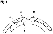
- FIG 5 an enlarged view of a contact surface 21 between a tire mounting tool 1 and a tire 20 is shown.
- the tire mounting tool 1 has in the Figure 5 a work area 5 with cup-shaped depressions 4 in the first surface 41.
- the cup-shaped depressions 4 reduce the contact surface 21 between the tire 10 and the working area 51.
- cavities 22 are formed between the tire 20 and the first surface 41, in which assembly paste or lubricant can collect or be stored.
- the second side 52 can have depressions 7 in the second surface 42.
- the depressions 7 can be formed by cup-shaped depressions 4 or by elongated incisions 9 according to the described exemplary embodiments of the first surface 51.
- lubricant or assembly paste can be stored in an area or transported into an area in which the second surface 52 comes into contact with the rim 10.
Landscapes
- Engineering & Computer Science (AREA)
- Mechanical Engineering (AREA)
- Tires In General (AREA)
Description
-
US 2014/359949 A1 offenbart einen Reifen-Kundendiensthammer, umfassend: einen Griffabschnitt; und einen Kopfabschnitt, wobei der Kopfabschnitt Folgendes umfasst: einen Schlagabschnitt; einen Vertiefungsabschnitt, der in einem Umfangsabschnitt des Schlagabschnitts gebildet ist; einen Keilabschnitt; und einen Körperabschnitt, der den Schlagabschnitt und den Keilabschnitt verbindet. Der Keilabschnitt weist einen wulstbrechenden Keil mit einer glatten oder abgeschrägten wulstbrechenden Kante und einem Hakenfortsatz mit einer glatten oder abgeschrägten wulstbrechenden Kante auf. Der wulstbrechende Keil weist ferner Vertiefungen auf, die dazu genutzt werden Schmiermittel zum Wulstbereich zu fördern, wenn der Hammer im Einsatz ist. -
US 2015/273959 A1 beschreibt einen Reifenlöffel zum Montieren oder Entfernen eines Reifens von einer Radfelge. Der Reifenlöffel umfasst einen Löffel und eine längliche Welle. Der Löffel kann zwischen einer Radfelge und einem darauf angeordneten Reifen eingesetzt werden. Die längliche Welle definiert einen Hebelarm, der vom Löffel entfernt ist und der konfiguriert ist, um eine Hebelkraft aufzunehmen und auf den Löffel zu übertragen, um einen Teil des Reifens um die Radfelge zu biegen. Ein Kraftelement erstreckt sich quer von der Welle in der Nähe des Löffels und zwischen dem Löffel und dem Hebelarm und ist konfiguriert, um eine Druckkraft aufzunehmen und auf den Löffel zu übertragen, um den Löffel zwischen dem Reifen und der Radfelge anzutreiben. Ein Griffteil des Löffels weist mindestens eine Nut auf, die konfiguriert ist, um eine Oberfläche des Reifens und / oder der Radfelge zu greifen. -
US 3 332 467 A beschreibt ein Abdrückwerkzeug zum Lösen eines Reifens von einer Felge. - Aus der
WO 2015/044920 A und dem DokumentEP0767098 ist eine Reifenmontagemaschine bekannt. Eine Reifenmontagemaschine weist normalerweise ein Reifenmontagewerkzeug auf, welches entweder automatisch durch die Reifenmontagemaschine bewegt wird oder durch einen Anwender in die benötigte Position bewegt wird. Es existieren auch Reifenmontagewerkzeuge als eigenständige Bauteile oder Werkzeuge, welche nicht mit einer Reifenmontagemaschine verbunden sind. Das Reifenmontagewerkzeug dient zur Montage oder Demontage eines Reifens auf eine Felge. Hierbei muss der Reifenwulst über das Felgenhorn der Felge bewegt werden. Dieser Vorgang ist nur mit einem sehr hohen Kraftaufwand möglich. Des Weiteren sollte die Reifenmontage und Demontage nur mit höchster Sorgfalt durchgeführt werden, da bereits kleine Risse in der Reifenoberfläche das Fahrverhalten negativ beeinflussen können oder zu einer Gefährdung im Straßenverkehr führen. - Das erfindungsgemäße Reifenmontagewerkzeug mit den Merkmalen gemäß des unabhängigen Anspruches hat den Vorteil, dass auf einer Oberfläche des Arbeitsbereiches Montagepaste oder Schmiermittel zwischen Arbeitsbereich und Reifen gespeichert wird bzw. dorthin transportiert wird, so dass die Reibungskräfte zwischen Reifen und Reifenmontagewerkzeug reduziert werden und die Wahrscheinlichkeit, dass das Rad beschädigt wird, reduziert wird.
- Bei einer glatten Oberfläche des Arbeitsbereiches wird das Schmiermittel oder die Montagepaste bereits nach wenigen Arbeitsschritten durch den engen Kontakt zwischen Reifen und Montagewerkzeug und die Bewegung des
- Montagewerkzeuges entlang des Reifens entfernt oder reduziert. Abhängig von der Form der Vertiefungen kann die Montagepaste oder das Schmiermittel in den Vertiefungen gespeichert werden oder durch die Bewegung des Montagewerkzeuges entlang des Reifens sogar bewusst in einen Bereich gedrückt oder transportiert werden, in den eine erhöhte Schmierung benötigt wird.
- Die Vertiefungen sind napfförmigen Vertiefungen, welche das Schmiermittel oder die Montagpaste in einem Hohlraum zwischen Reifen und Arbeitsbereich speichern, oder die Vertiefungen werden durch langgestreckte Einschnitt gebildet, wobei der langgestreckte Einschnitt von einem ersten Ende zu einem zweiten Ende eine Vergrößerung seiner Breite und eine Vergrößerung seiner Tiefe aufweist. Dies ist vorteilhaft da diese Geometrie zusammen mit einer gerichteten Bewegung des Montagewerkzeuges entlang des Reifens das Schmiermittel oder die Montagepaste von einem Ende der langegestreckten Vertiefung zum anderen Ende der langgestreckten Vertiefung transportiert.
- In den abhängigen Ansprüchen sind vorteilhafte Ausgestaltungen und Weiterbildungen der erfindungsgemäßen Vorrichtung und des erfindungsgemäßen Verfahrens angegeben.
- Es ist von Vorteil, wenn die zweite Seite Vertiefungen in einer zweiten Oberfläche aufweist, so dass auf einer Oberfläche des Arbeitsbereiches, welche der Felge zugewandt ist oder die Felge berührt, Montagepaste oder Schmiermittel gespeichert wird bzw. dorthin transportiert wird, so dass die Reibungskräfte reduziert werden, falls ein Kontakt zwischen Felge und Arbeitsbereich auftritt.
- Die Tiefe und die Breite der langgestreckten Einschnitte unterscheidet sich nicht wesentlich von der Tiefe und Breite der napfförmigen Vertiefungen. Die Länge der langgestreckten Einschnitte kann beliebig gewählt werden.
- Eine Veränderung der Tiefe und/oder der Breite des langestreckte Einschnittes ist vorteilhaft, da Schmiermittel und/oder Montagepaste bewusst in einen bestimmten Bereich entlang des langgestreckten Abschnittes transportiert wird.
- Auch eine V-förmige Anordnung mehrere langgestreckten Einschnitte zueinander ist vorteilhaft, da abhängig von der Bewegungsrichtung des Montagewerkzeuges entlang des Reifens Schmiermittel oder Montagepaste entweder in den Bereich der gemeinsamen Spitze oder zu den voneinander beabstandeten Enden transportiert wird.
- Bevorzugte Ausführungsbeispiele der Erfindung sind in der Zeichnung dargestellt und in der nachfolgenden Beschreibung näher erläutert.
- Es zeigen:
-
Figur 1 eine schematische Darstellung einer Reifenmontagemaschine mit Reifenmontagewerkzeug, bei der Montage eines Reifens auf eine Felge, -
Figur 2 ein Reifenmontagewerkzeug gemäß dem Stand der Technik, -
Figur 3 ein Reifenmontagewerkzeug gemäß einem ersten Ausführungsbeispiel, -
Figur 4 ein Reifenmontagewerkzeug gemäß einem zweiten Ausführungsbeispiel, -
Figur 5 eine vergrößerte Ansicht einer Kontaktfläche zwischen einem Reifenmontagewerkzeug und einem Reifen. - Die schematische Ansicht gemäß
Figur 1 zeigt eine Reifenmontagemaschine 2 mit einem Reifenmontagewerkzeug 1, welches zum Montieren und/oder Demontieren eines Reifens 20 auf/von eine Felge 10 dient. Das Reifenmontagewerkzeug 1 weist einen Hand- oder Maschinenbereich 8 und einen Arbeitsbereich 5 auf. Der Hand-oder Maschinenbereich 8 kann mit der Reifenmontagemaschine 2 verbunden sein. Hierbei ist eine Ansteuerung bzw. Bewegung des Reifenmontagewerkzeuges 1 durch die Reifenmontagemaschine 2 möglich. Alternativ kann das Reifenmontagewerkzeug 1 durch einen Anwender an die relevanten Stellen zwischen Reifen 20 und Felge 10 geführt werden. - Das Reifenmontagewerkzeug 1 kann auch als eigenständiges Werkzeug ausgebildet sein. In diesem Fall ist das Reifenmontagewerkzeug 1 nicht mit der Reifenmontagemaschine 2 verbunden ist. und muss durch einen Anwender bewegt werden.
- Der Anwender kann das Reifenmontagewerkzeug 1 im Hand- oder Maschinenbereich 8 greifen und an die relevanten Stellen zwischen Reifen 20 und Felge 10 führen.
- Der Arbeitsbereich 5 kann eine Vielzahl von unterschiedlichen Geometrien aufweisen, welche zum Montieren und/oder Demontieren eines Reifens 20 auf eine Felge 10 geeignet sind.
- Die Geometrie des Arbeitsbereiches 5 kann eine komplexe dreidimensionale Form oder eine simple Formen, beispielsweise ein verdickter abgeflachter quaderförmiger Stab, wie in
Figur 2 dargestellt, sein. Der Arbeitsbereich 5 weist eine erste Seite 51 mit einer ersten Oberfläche 41, welche beim Montieren und/oder Demontieren im Kontakt mit dem Reifen 20 ist, auf. Des Weiteren weist der Arbeitsbereich 5 eine zweite Seite 52 mit einer zweiten Oberfläche 42, welche beim Montieren und/oder Demontieren der Felge 10 zugewandt ist, auf. Die erste Seite 51 und die zweite Seite 52 sind meist gegenüber voneinander angeordnet, sie können aber auch in einen Winkel zueinander ausgerichtet sein. - Bei der Montage und Demontage eines Reifens 20 auf oder von einer Felge 10 treten sehr große Kräfte auf, da der Reifenwulst über das Felgenhorn gebracht werden muss. Während des Montier oder Demontierprozesses wird normalerweise eine Montagepaste oder Schmiermittel auf den Reifenwulst und das Reifenmontagewerkzeug 1 gebracht. Durch die Montagepaste oder das Schmiermittel sollen Beschädigungen am Reifen 20 verhindert werden.
- Aus dem Stand der Technik sind nur Montagewerkzeuge 1 mit Arbeitsbereichen 5, die eine glatte Oberfläche, gemäß
Figur 2 , aufweisen, bekannt. Während das Reifenmontagewerkzeug 1 mit dem Reifen 20 in Kontakt tritt, wird die Montagepaste oder das Schmiermittel verdrängt bzw. weggeschoben und muss auf diesem ständig erneuert werden. Auch können die Reibungskräfte zwischen Reifen 20 und Arbeitsbereich 5 des Montagewerkzeuges 1 nicht im gewünschten Maß reduziert werden. - Gemäß der vorgeschlagenen Erfindung weist die erste Seite 51 des Arbeitsbereiches 5 Vertiefungen 7 in einer ersten Oberfläche 41 auf. Die Vertiefungen 7 können die Montagepaste oder das Schmiermittel zwischen dem Reifen 20 und dem Arbeitsbereich 5 speichern oder in einen Bereich leiten, in dem besonders viel Montagepaste oder Schmiermittel benötigt wird.
- In
Figur 3 ist ein Reifenmontagewerkzeug 1 gemäß einem ersten Ausführungsbeispiel gezeigt. Die Vertiefungen 7 werden durch napfförmige Vertiefungen 4, also im Wesentlichen kreisrunde Vertiefungen, gebildet. Die napfförmigen Vertiefungen 4 bilden dabei eine regelmäßige Oberflächenstruktur ähnlich, wie bei einem Golfball. Diese Oberflächenstruktur ist auch unter dem Begriff Dimples bekannt. Die Vielzahl von napfförmigen Vertiefungen 4 sind zueinander beabstandet und weisen eine Tiefe t auf, welche weniger als 4 mm, vorzugsweise 2mm bis 2,5 mm, beträgt. Der Durchmesser d der napfförmigen Vertiefungen 4 ist größer als deren Tiefe t und liegt im Bereich von 3 mm bis 6 mm, vorzugsweise 4 mm bis 5 mm. - In
Figur 4 ist ein Reifenmontagewerkzeug 1 gemäß einem zweiten Ausführungsbeispiel gezeigt. Die Vertiefungen 7 werden durch langgestreckte Einschnitte 9 gebildet. Die langestreckten Einschnitte 9 sind dabei V-förmig zueinander angeordnet. Es ist jedoch auch jede andere vorteilhafte Anordnung der langestreckten Einschnitte 9 möglich. - Die langgestreckten Einschnitte 9 können gerade verlaufen, zick-zack-förmig, wellenförmig oder treppenförmig verlaufen.
- Um die Montagepaste oder das Schmiermittel in einen Bereich zu leiten, in dem besonders viel Montagepaste oder Schmiermittel benötigt wird, kann sich die Breite b und/oder Tiefe a eines langgestreckten Einschnittes 7 über die Länge verändern.
- Gemäß einem weiteren Ausführungsbeispiel kann von einem ersten Ende zu einem zweiten Ende des langgestreckten Einschnittes 7 eine Vergrößerung der Breite und eine Vergrößerung der Tiefe stattfinden. Der langgestreckte Einschnitt kann als halbkreisförmiger Tunnel oder als rechteckiger Tunnel ausgebildet sein. Der Übergang von einer Fläche auf die nächste Fläche kann einen Radius aufweisen.
- In
Figur 5 ist eine vergrößerte Ansicht einer Kontaktfläche 21 zwischen einem Reifenmontagewerkzeug 1 und einem Reifen 20 gezeigt. Das Reifenmontagewerkzeug 1 weist in derFigur 5 einen Arbeitsbereich 5 mit napfförmigen Vertiefungen 4 in der ersten Oberfläche 41 auf. Durch die napfförmigen Vertiefungen 4 reduziert sich die Kontaktfläche 21 zwischen Reifen 10 und Arbeitsbereich 51. Des Weiteren bilden sich Hohlräume 22 zwischen dem Reifen 20 und der ersten Oberfläche 41, in denen sich Montagepaste oder Schmiermittel ansammeln bzw. gespeichert werden kann. - Gemäß einem weiteren Ausführungsbeispiel kann die zweite Seite 52 Vertiefungen 7 in der zweiten Oberfläche 42 aufweisen. Die Vertiefungen 7 können durch napfförmige Vertiefungen 4 oder durch langgestreckte Einschnitte 9 gemäß der beschriebenen Ausführungsbeispiele der ersten Oberfläche 51 gebildet werden.
- Durch die Vertiefungen 7 kann Schmiermittel oder Montagepaste in einem Bereich gespeichert werden oder in einen Bereich transportiert werden, in dem die zweite Oberfläche 52 mit der Felge 10 in Kontakt tritt.
Claims (4)
- Reifenmontagewerkzeug (1) zum Montieren und/oder Demontieren eines Reifens (20) auf eine Felge mit einem Hand- oder Maschinenbereich (8) und einem Arbeitsbereich (5), welcher zwischen dem Reifen (20) und der Felge (10) angeordnet wird, wobei der Arbeitsbereich (5) eine erste Seite (51) mit einer ersten Oberfläche (41), welche beim Montieren und/oder Demontieren im Kontakt mit dem Reifen (20) ist, und eine zweite Seite (52) mit einer zweiten Oberfläche (42), welche beim Montieren und/oder Demontieren der Felge (10) zugewandt ist, aufweist, wobei die erste Seite (51) Vertiefungen (4) in der ersten Oberfläche (41) aufweist; dadurch gekennzeichnet,
dass die Vertiefungen (4) napfförmige Vertiefungen (4) sind; oder
dass die Vertiefungen (4) durch langgestreckte Einschnitte (9) gebildet werden und von einem ersten Ende zu einem zweiten Ende eine Vergrößerung ihrer Breite und eine Vergrößerung ihrer Tiefe aufweisen. - Reifenmontagewerkzeug (1) nach Anspruch 1,
dadurch gekennzeichnet, dass die zweite Seite (52) Vertiefungen (4) in der zweiten Oberfläche (42) aufweist. - Reifenmontagewerkzeug (1) nach Anspruch 1 oder 2,
dadurch gekennzeichnet, dass die langgestreckten Einschnitte (9) gerade verlaufend, zick-zack-förmig, wellenförmig oder treppenförmig ausgebildet sind. - Reifenmontagewerkzeug (1) nach einem der Ansprüche 1 bis 3,
dadurch gekennzeichnet, dass mehrere langestreckten Einschnitte (9) V-förmig zueinander angeordnet sind.
Applications Claiming Priority (2)
| Application Number | Priority Date | Filing Date | Title |
|---|---|---|---|
| DE102016217283.2A DE102016217283A1 (de) | 2016-09-12 | 2016-09-12 | Reifenmontagewerkzeug |
| PCT/EP2017/070290 WO2018046220A1 (de) | 2016-09-12 | 2017-08-10 | Reifenmontagewerkzeug |
Publications (2)
| Publication Number | Publication Date |
|---|---|
| EP3523146A1 EP3523146A1 (de) | 2019-08-14 |
| EP3523146B1 true EP3523146B1 (de) | 2020-11-18 |
Family
ID=59745257
Family Applications (1)
| Application Number | Title | Priority Date | Filing Date |
|---|---|---|---|
| EP17758818.3A Not-in-force EP3523146B1 (de) | 2016-09-12 | 2017-08-10 | Reifenmontagewerkzeug |
Country Status (4)
| Country | Link |
|---|---|
| EP (1) | EP3523146B1 (de) |
| CN (1) | CN109641497B (de) |
| DE (1) | DE102016217283A1 (de) |
| WO (1) | WO2018046220A1 (de) |
Family Cites Families (8)
| Publication number | Priority date | Publication date | Assignee | Title |
|---|---|---|---|---|
| US3332467A (en) * | 1965-07-12 | 1967-07-25 | Mrs W E Horrocks | Bead breaking tool |
| TW343179B (en) | 1995-10-02 | 1998-10-21 | Maciss R L | Burst protection device for tire removing machines a burst protection device for tire removing machines of the type having a platform on which a wheel can be located and an arm supporting a bead extractor. |
| US5740848A (en) * | 1995-11-16 | 1998-04-21 | Goracy; Grant | Tire changer tool set |
| JP2002225516A (ja) * | 2001-02-05 | 2002-08-14 | Sumitomo Rubber Ind Ltd | 空気入りタイヤ |
| US7083238B2 (en) * | 2004-08-23 | 2006-08-01 | Alcoa, Inc. | Multi-piece aluminum wheel and associated method |
| US9162543B2 (en) * | 2013-06-07 | 2015-10-20 | Bosch Automotive Service Solutions Inc. | Tire service hammer |
| ITMO20130275A1 (it) | 2013-09-30 | 2015-03-31 | Sicam Srl | Macchina smontagomme |
| US20150273959A1 (en) * | 2014-03-28 | 2015-10-01 | Bosch Automotive Service Solutions Inc. | Kick Start Tire Spoon and Grip for a Kick Start Tire Spoon |
-
2016
- 2016-09-12 DE DE102016217283.2A patent/DE102016217283A1/de not_active Withdrawn
-
2017
- 2017-08-10 CN CN201780055718.2A patent/CN109641497B/zh not_active Expired - Fee Related
- 2017-08-10 WO PCT/EP2017/070290 patent/WO2018046220A1/de not_active Ceased
- 2017-08-10 EP EP17758818.3A patent/EP3523146B1/de not_active Not-in-force
Also Published As
| Publication number | Publication date |
|---|---|
| WO2018046220A1 (de) | 2018-03-15 |
| CN109641497B (zh) | 2021-03-09 |
| CN109641497A (zh) | 2019-04-16 |
| DE102016217283A1 (de) | 2018-03-15 |
| EP3523146A1 (de) | 2019-08-14 |
Similar Documents
| Publication | Publication Date | Title |
|---|---|---|
| DE102012104298B4 (de) | Werkzeug | |
| EP3213847A1 (de) | Oszillationswerkzeug | |
| DE1273266B (de) | Bohrspitze fuer selbstbohrende Schrauben sowie Vorrichtung und Verfahren zur Herstellung derselben | |
| DE3127740A1 (de) | Schlagwerkzeug mit einem zum schlagen und einem zum schneiden aktiven ende, sowie ein verfahren zu dessen herstellung | |
| DE102009012243B4 (de) | Stanzmutter, Stanzmutter-Vorrichtung und Stanzmutter-Blechverbindung | |
| EP2699401B1 (de) | Bohrwerkzeug bzw. verfahren zur herstellung eines bohrwerkzeugs | |
| DE102012217094A1 (de) | Hubtrennwerkzeug | |
| EP3523146B1 (de) | Reifenmontagewerkzeug | |
| CH649936A5 (de) | Vorrichtung zum abschraegen einer werkstueckkante. | |
| EP3112042B1 (de) | Stanzwerkzeug und stanzverfahren | |
| EP2998068B1 (de) | Zentrumsspanner mit schnellwechselbacken | |
| DE3420857A1 (de) | Greifvorrichtung mit greiferbacke | |
| DE102013001918B4 (de) | Verfahren zur Herstellung eines Sacklochs in einem metallischen Körper sowie Verwendung eines derartigen Verfahrens | |
| DE202012100409U1 (de) | Drahtvorschubrolle | |
| DE202009001991U1 (de) | Zweistufiger Werkzeugverbinder | |
| DE10026203A1 (de) | Vorrichtung zum Entfernen von Beulen aus Blech | |
| EP4267788B1 (de) | Taftnadel | |
| DE102016219713B4 (de) | Stanzwerkzeug, Werkzeugmaschine, Verfahren zur Bauteilbearbeitung und Verwendung eines Stanzwerkzeugs | |
| DE3626000C2 (de) | ||
| DE3447521C2 (de) | ||
| DE2315660A1 (de) | Reibahle | |
| DE69600170T2 (de) | Schneidteil eines Bohrmeissels | |
| DE102017108271A1 (de) | Kolben | |
| EP4202399A1 (de) | Verfahren zur oberflächenbearbeitung eines bauteils eines kraftfahrzeugprüfstandes und bauteil eines kraftfahrzeugprüfstandes | |
| DE1575167C (de) | Bohrschraube |
Legal Events
| Date | Code | Title | Description |
|---|---|---|---|
| STAA | Information on the status of an ep patent application or granted ep patent |
Free format text: STATUS: UNKNOWN |
|
| STAA | Information on the status of an ep patent application or granted ep patent |
Free format text: STATUS: THE INTERNATIONAL PUBLICATION HAS BEEN MADE |
|
| PUAI | Public reference made under article 153(3) epc to a published international application that has entered the european phase |
Free format text: ORIGINAL CODE: 0009012 |
|
| STAA | Information on the status of an ep patent application or granted ep patent |
Free format text: STATUS: REQUEST FOR EXAMINATION WAS MADE |
|
| 17P | Request for examination filed |
Effective date: 20190625 |
|
| AK | Designated contracting states |
Kind code of ref document: A1 Designated state(s): AL AT BE BG CH CY CZ DE DK EE ES FI FR GB GR HR HU IE IS IT LI LT LU LV MC MK MT NL NO PL PT RO RS SE SI SK SM TR |
|
| AX | Request for extension of the european patent |
Extension state: BA ME |
|
| DAV | Request for validation of the european patent (deleted) | ||
| DAX | Request for extension of the european patent (deleted) | ||
| GRAP | Despatch of communication of intention to grant a patent |
Free format text: ORIGINAL CODE: EPIDOSNIGR1 |
|
| STAA | Information on the status of an ep patent application or granted ep patent |
Free format text: STATUS: GRANT OF PATENT IS INTENDED |
|
| INTG | Intention to grant announced |
Effective date: 20200602 |
|
| GRAS | Grant fee paid |
Free format text: ORIGINAL CODE: EPIDOSNIGR3 |
|
| GRAA | (expected) grant |
Free format text: ORIGINAL CODE: 0009210 |
|
| STAA | Information on the status of an ep patent application or granted ep patent |
Free format text: STATUS: THE PATENT HAS BEEN GRANTED |
|
| AK | Designated contracting states |
Kind code of ref document: B1 Designated state(s): AL AT BE BG CH CY CZ DE DK EE ES FI FR GB GR HR HU IE IS IT LI LT LU LV MC MK MT NL NO PL PT RO RS SE SI SK SM TR |
|
| REG | Reference to a national code |
Ref country code: GB Ref legal event code: FG4D Free format text: NOT ENGLISH |
|
| REG | Reference to a national code |
Ref country code: CH Ref legal event code: EP |
|
| REG | Reference to a national code |
Ref country code: IE Ref legal event code: FG4D Free format text: LANGUAGE OF EP DOCUMENT: GERMAN |
|
| REG | Reference to a national code |
Ref country code: DE Ref legal event code: R096 Ref document number: 502017008288 Country of ref document: DE |
|
| REG | Reference to a national code |
Ref country code: AT Ref legal event code: REF Ref document number: 1335371 Country of ref document: AT Kind code of ref document: T Effective date: 20201215 |
|
| REG | Reference to a national code |
Ref country code: NL Ref legal event code: MP Effective date: 20201118 |
|
| PG25 | Lapsed in a contracting state [announced via postgrant information from national office to epo] |
Ref country code: RS Free format text: LAPSE BECAUSE OF FAILURE TO SUBMIT A TRANSLATION OF THE DESCRIPTION OR TO PAY THE FEE WITHIN THE PRESCRIBED TIME-LIMIT Effective date: 20201118 Ref country code: PT Free format text: LAPSE BECAUSE OF FAILURE TO SUBMIT A TRANSLATION OF THE DESCRIPTION OR TO PAY THE FEE WITHIN THE PRESCRIBED TIME-LIMIT Effective date: 20210318 Ref country code: NO Free format text: LAPSE BECAUSE OF FAILURE TO SUBMIT A TRANSLATION OF THE DESCRIPTION OR TO PAY THE FEE WITHIN THE PRESCRIBED TIME-LIMIT Effective date: 20210218 Ref country code: FI Free format text: LAPSE BECAUSE OF FAILURE TO SUBMIT A TRANSLATION OF THE DESCRIPTION OR TO PAY THE FEE WITHIN THE PRESCRIBED TIME-LIMIT Effective date: 20201118 Ref country code: GR Free format text: LAPSE BECAUSE OF FAILURE TO SUBMIT A TRANSLATION OF THE DESCRIPTION OR TO PAY THE FEE WITHIN THE PRESCRIBED TIME-LIMIT Effective date: 20210219 |
|
| PG25 | Lapsed in a contracting state [announced via postgrant information from national office to epo] |
Ref country code: LV Free format text: LAPSE BECAUSE OF FAILURE TO SUBMIT A TRANSLATION OF THE DESCRIPTION OR TO PAY THE FEE WITHIN THE PRESCRIBED TIME-LIMIT Effective date: 20201118 Ref country code: IS Free format text: LAPSE BECAUSE OF FAILURE TO SUBMIT A TRANSLATION OF THE DESCRIPTION OR TO PAY THE FEE WITHIN THE PRESCRIBED TIME-LIMIT Effective date: 20210318 Ref country code: PL Free format text: LAPSE BECAUSE OF FAILURE TO SUBMIT A TRANSLATION OF THE DESCRIPTION OR TO PAY THE FEE WITHIN THE PRESCRIBED TIME-LIMIT Effective date: 20201118 Ref country code: SE Free format text: LAPSE BECAUSE OF FAILURE TO SUBMIT A TRANSLATION OF THE DESCRIPTION OR TO PAY THE FEE WITHIN THE PRESCRIBED TIME-LIMIT Effective date: 20201118 Ref country code: BG Free format text: LAPSE BECAUSE OF FAILURE TO SUBMIT A TRANSLATION OF THE DESCRIPTION OR TO PAY THE FEE WITHIN THE PRESCRIBED TIME-LIMIT Effective date: 20210218 |
|
| REG | Reference to a national code |
Ref country code: DE Ref legal event code: R082 Ref document number: 502017008288 Country of ref document: DE Representative=s name: SCHMITT-NILSON SCHRAUD WAIBEL WOHLFROM PATENTA, DE Ref country code: DE Ref legal event code: R081 Ref document number: 502017008288 Country of ref document: DE Owner name: SICAM S.R.I., IT Free format text: FORMER OWNER: BEISSBARTH GMBH, 80993 MUENCHEN, DE |
|
| REG | Reference to a national code |
Ref country code: LT Ref legal event code: MG9D |
|
| PG25 | Lapsed in a contracting state [announced via postgrant information from national office to epo] |
Ref country code: HR Free format text: LAPSE BECAUSE OF FAILURE TO SUBMIT A TRANSLATION OF THE DESCRIPTION OR TO PAY THE FEE WITHIN THE PRESCRIBED TIME-LIMIT Effective date: 20201118 |
|
| RAP2 | Party data changed (patent owner data changed or rights of a patent transferred) |
Owner name: SICAM S.R.L. |
|
| PG25 | Lapsed in a contracting state [announced via postgrant information from national office to epo] |
Ref country code: SK Free format text: LAPSE BECAUSE OF FAILURE TO SUBMIT A TRANSLATION OF THE DESCRIPTION OR TO PAY THE FEE WITHIN THE PRESCRIBED TIME-LIMIT Effective date: 20201118 Ref country code: RO Free format text: LAPSE BECAUSE OF FAILURE TO SUBMIT A TRANSLATION OF THE DESCRIPTION OR TO PAY THE FEE WITHIN THE PRESCRIBED TIME-LIMIT Effective date: 20201118 Ref country code: SM Free format text: LAPSE BECAUSE OF FAILURE TO SUBMIT A TRANSLATION OF THE DESCRIPTION OR TO PAY THE FEE WITHIN THE PRESCRIBED TIME-LIMIT Effective date: 20201118 Ref country code: EE Free format text: LAPSE BECAUSE OF FAILURE TO SUBMIT A TRANSLATION OF THE DESCRIPTION OR TO PAY THE FEE WITHIN THE PRESCRIBED TIME-LIMIT Effective date: 20201118 Ref country code: CZ Free format text: LAPSE BECAUSE OF FAILURE TO SUBMIT A TRANSLATION OF THE DESCRIPTION OR TO PAY THE FEE WITHIN THE PRESCRIBED TIME-LIMIT Effective date: 20201118 Ref country code: LT Free format text: LAPSE BECAUSE OF FAILURE TO SUBMIT A TRANSLATION OF THE DESCRIPTION OR TO PAY THE FEE WITHIN THE PRESCRIBED TIME-LIMIT Effective date: 20201118 |
|
| REG | Reference to a national code |
Ref country code: DE Ref legal event code: R097 Ref document number: 502017008288 Country of ref document: DE |
|
| PG25 | Lapsed in a contracting state [announced via postgrant information from national office to epo] |
Ref country code: DK Free format text: LAPSE BECAUSE OF FAILURE TO SUBMIT A TRANSLATION OF THE DESCRIPTION OR TO PAY THE FEE WITHIN THE PRESCRIBED TIME-LIMIT Effective date: 20201118 |
|
| PLBE | No opposition filed within time limit |
Free format text: ORIGINAL CODE: 0009261 |
|
| STAA | Information on the status of an ep patent application or granted ep patent |
Free format text: STATUS: NO OPPOSITION FILED WITHIN TIME LIMIT |
|
| 26N | No opposition filed |
Effective date: 20210819 |
|
| PG25 | Lapsed in a contracting state [announced via postgrant information from national office to epo] |
Ref country code: NL Free format text: LAPSE BECAUSE OF FAILURE TO SUBMIT A TRANSLATION OF THE DESCRIPTION OR TO PAY THE FEE WITHIN THE PRESCRIBED TIME-LIMIT Effective date: 20201118 Ref country code: AL Free format text: LAPSE BECAUSE OF FAILURE TO SUBMIT A TRANSLATION OF THE DESCRIPTION OR TO PAY THE FEE WITHIN THE PRESCRIBED TIME-LIMIT Effective date: 20201118 |
|
| PGFP | Annual fee paid to national office [announced via postgrant information from national office to epo] |
Ref country code: IT Payment date: 20210831 Year of fee payment: 5 |
|
| PG25 | Lapsed in a contracting state [announced via postgrant information from national office to epo] |
Ref country code: SI Free format text: LAPSE BECAUSE OF FAILURE TO SUBMIT A TRANSLATION OF THE DESCRIPTION OR TO PAY THE FEE WITHIN THE PRESCRIBED TIME-LIMIT Effective date: 20201118 |
|
| PG25 | Lapsed in a contracting state [announced via postgrant information from national office to epo] |
Ref country code: ES Free format text: LAPSE BECAUSE OF FAILURE TO SUBMIT A TRANSLATION OF THE DESCRIPTION OR TO PAY THE FEE WITHIN THE PRESCRIBED TIME-LIMIT Effective date: 20201118 |
|
| PGFP | Annual fee paid to national office [announced via postgrant information from national office to epo] |
Ref country code: DE Payment date: 20211027 Year of fee payment: 5 |
|
| REG | Reference to a national code |
Ref country code: CH Ref legal event code: PL |
|
| PG25 | Lapsed in a contracting state [announced via postgrant information from national office to epo] |
Ref country code: MC Free format text: LAPSE BECAUSE OF FAILURE TO SUBMIT A TRANSLATION OF THE DESCRIPTION OR TO PAY THE FEE WITHIN THE PRESCRIBED TIME-LIMIT Effective date: 20201118 |
|
| REG | Reference to a national code |
Ref country code: BE Ref legal event code: MM Effective date: 20210831 |
|
| GBPC | Gb: european patent ceased through non-payment of renewal fee |
Effective date: 20210810 |
|
| PG25 | Lapsed in a contracting state [announced via postgrant information from national office to epo] |
Ref country code: LI Free format text: LAPSE BECAUSE OF NON-PAYMENT OF DUE FEES Effective date: 20210831 Ref country code: CH Free format text: LAPSE BECAUSE OF NON-PAYMENT OF DUE FEES Effective date: 20210831 |
|
| PG25 | Lapsed in a contracting state [announced via postgrant information from national office to epo] |
Ref country code: IS Free format text: LAPSE BECAUSE OF FAILURE TO SUBMIT A TRANSLATION OF THE DESCRIPTION OR TO PAY THE FEE WITHIN THE PRESCRIBED TIME-LIMIT Effective date: 20210318 Ref country code: LU Free format text: LAPSE BECAUSE OF NON-PAYMENT OF DUE FEES Effective date: 20210810 |
|
| PG25 | Lapsed in a contracting state [announced via postgrant information from national office to epo] |
Ref country code: IE Free format text: LAPSE BECAUSE OF NON-PAYMENT OF DUE FEES Effective date: 20210810 Ref country code: GB Free format text: LAPSE BECAUSE OF NON-PAYMENT OF DUE FEES Effective date: 20210810 Ref country code: FR Free format text: LAPSE BECAUSE OF NON-PAYMENT OF DUE FEES Effective date: 20210831 Ref country code: BE Free format text: LAPSE BECAUSE OF NON-PAYMENT OF DUE FEES Effective date: 20210831 |
|
| REG | Reference to a national code |
Ref country code: DE Ref legal event code: R119 Ref document number: 502017008288 Country of ref document: DE |
|
| PG25 | Lapsed in a contracting state [announced via postgrant information from national office to epo] |
Ref country code: CY Free format text: LAPSE BECAUSE OF FAILURE TO SUBMIT A TRANSLATION OF THE DESCRIPTION OR TO PAY THE FEE WITHIN THE PRESCRIBED TIME-LIMIT Effective date: 20201118 |
|
| PG25 | Lapsed in a contracting state [announced via postgrant information from national office to epo] |
Ref country code: IT Free format text: LAPSE BECAUSE OF NON-PAYMENT OF DUE FEES Effective date: 20220810 Ref country code: HU Free format text: LAPSE BECAUSE OF FAILURE TO SUBMIT A TRANSLATION OF THE DESCRIPTION OR TO PAY THE FEE WITHIN THE PRESCRIBED TIME-LIMIT; INVALID AB INITIO Effective date: 20170810 Ref country code: DE Free format text: LAPSE BECAUSE OF NON-PAYMENT OF DUE FEES Effective date: 20230301 |
|
| REG | Reference to a national code |
Ref country code: AT Ref legal event code: MM01 Ref document number: 1335371 Country of ref document: AT Kind code of ref document: T Effective date: 20220810 |
|
| PG25 | Lapsed in a contracting state [announced via postgrant information from national office to epo] |
Ref country code: AT Free format text: LAPSE BECAUSE OF NON-PAYMENT OF DUE FEES Effective date: 20220810 |
|
| PG25 | Lapsed in a contracting state [announced via postgrant information from national office to epo] |
Ref country code: MK Free format text: LAPSE BECAUSE OF FAILURE TO SUBMIT A TRANSLATION OF THE DESCRIPTION OR TO PAY THE FEE WITHIN THE PRESCRIBED TIME-LIMIT Effective date: 20201118 |
|
| PG25 | Lapsed in a contracting state [announced via postgrant information from national office to epo] |
Ref country code: TR Free format text: LAPSE BECAUSE OF FAILURE TO SUBMIT A TRANSLATION OF THE DESCRIPTION OR TO PAY THE FEE WITHIN THE PRESCRIBED TIME-LIMIT Effective date: 20201118 |
|
| PG25 | Lapsed in a contracting state [announced via postgrant information from national office to epo] |
Ref country code: MT Free format text: LAPSE BECAUSE OF FAILURE TO SUBMIT A TRANSLATION OF THE DESCRIPTION OR TO PAY THE FEE WITHIN THE PRESCRIBED TIME-LIMIT Effective date: 20201118 |