EP3520974B1 - Bandschneidesystem und verfahren zum schneiden eines bandes - Google Patents
Bandschneidesystem und verfahren zum schneiden eines bandes Download PDFInfo
- Publication number
- EP3520974B1 EP3520974B1 EP19154863.5A EP19154863A EP3520974B1 EP 3520974 B1 EP3520974 B1 EP 3520974B1 EP 19154863 A EP19154863 A EP 19154863A EP 3520974 B1 EP3520974 B1 EP 3520974B1
- Authority
- EP
- European Patent Office
- Prior art keywords
- tape
- quality
- sections
- web
- length
- Prior art date
- Legal status (The legal status is an assumption and is not a legal conclusion. Google has not performed a legal analysis and makes no representation as to the accuracy of the status listed.)
- Active
Links
Images


Classifications
-
- B—PERFORMING OPERATIONS; TRANSPORTING
- B29—WORKING OF PLASTICS; WORKING OF SUBSTANCES IN A PLASTIC STATE IN GENERAL
- B29C—SHAPING OR JOINING OF PLASTICS; SHAPING OF MATERIAL IN A PLASTIC STATE, NOT OTHERWISE PROVIDED FOR; AFTER-TREATMENT OF THE SHAPED PRODUCTS, e.g. REPAIRING
- B29C70/00—Shaping composites, i.e. plastics material comprising reinforcements, fillers or preformed parts, e.g. inserts
- B29C70/04—Shaping composites, i.e. plastics material comprising reinforcements, fillers or preformed parts, e.g. inserts comprising reinforcements only, e.g. self-reinforcing plastics
- B29C70/28—Shaping operations therefor
- B29C70/54—Component parts, details or accessories; Auxiliary operations, e.g. feeding or storage of prepregs or SMC after impregnation or during ageing
- B29C70/545—Perforating, cutting or machining during or after moulding
-
- B—PERFORMING OPERATIONS; TRANSPORTING
- B26—HAND CUTTING TOOLS; CUTTING; SEVERING
- B26D—CUTTING; DETAILS COMMON TO MACHINES FOR PERFORATING, PUNCHING, CUTTING-OUT, STAMPING-OUT OR SEVERING
- B26D5/00—Arrangements for operating and controlling machines or devices for cutting, cutting-out, stamping-out, punching, perforating, or severing by means other than cutting
- B26D5/007—Control means comprising cameras, vision or image processing systems
-
- B—PERFORMING OPERATIONS; TRANSPORTING
- B26—HAND CUTTING TOOLS; CUTTING; SEVERING
- B26D—CUTTING; DETAILS COMMON TO MACHINES FOR PERFORATING, PUNCHING, CUTTING-OUT, STAMPING-OUT OR SEVERING
- B26D5/00—Arrangements for operating and controlling machines or devices for cutting, cutting-out, stamping-out, punching, perforating, or severing by means other than cutting
- B26D5/005—Computer numerical control means
-
- G—PHYSICS
- G05—CONTROLLING; REGULATING
- G05B—CONTROL OR REGULATING SYSTEMS IN GENERAL; FUNCTIONAL ELEMENTS OF SUCH SYSTEMS; MONITORING OR TESTING ARRANGEMENTS FOR SUCH SYSTEMS OR ELEMENTS
- G05B19/00—Program-control systems
- G05B19/02—Program-control systems electric
- G05B19/418—Total factory control, i.e. centrally controlling a plurality of machines, e.g. direct or distributed numerical control [DNC], flexible manufacturing systems [FMS], integrated manufacturing systems [IMS] or computer integrated manufacturing [CIM]
- G05B19/41875—Total factory control, i.e. centrally controlling a plurality of machines, e.g. direct or distributed numerical control [DNC], flexible manufacturing systems [FMS], integrated manufacturing systems [IMS] or computer integrated manufacturing [CIM] characterised by quality surveillance of production
-
- B—PERFORMING OPERATIONS; TRANSPORTING
- B29—WORKING OF PLASTICS; WORKING OF SUBSTANCES IN A PLASTIC STATE IN GENERAL
- B29C—SHAPING OR JOINING OF PLASTICS; SHAPING OF MATERIAL IN A PLASTIC STATE, NOT OTHERWISE PROVIDED FOR; AFTER-TREATMENT OF THE SHAPED PRODUCTS, e.g. REPAIRING
- B29C70/00—Shaping composites, i.e. plastics material comprising reinforcements, fillers or preformed parts, e.g. inserts
- B29C70/04—Shaping composites, i.e. plastics material comprising reinforcements, fillers or preformed parts, e.g. inserts comprising reinforcements only, e.g. self-reinforcing plastics
- B29C70/28—Shaping operations therefor
- B29C70/30—Shaping by lay-up, i.e. applying fibres, tape or broadsheet on a mould, former or core; Shaping by spray-up, i.e. spraying of fibres on a mould, former or core
- B29C70/38—Automated lay-up, e.g. using robots, laying filaments according to predetermined patterns
- B29C70/386—Automated tape laying [ATL]
-
- Y—GENERAL TAGGING OF NEW TECHNOLOGICAL DEVELOPMENTS; GENERAL TAGGING OF CROSS-SECTIONAL TECHNOLOGIES SPANNING OVER SEVERAL SECTIONS OF THE IPC; TECHNICAL SUBJECTS COVERED BY FORMER USPC CROSS-REFERENCE ART COLLECTIONS [XRACs] AND DIGESTS
- Y02—TECHNOLOGIES OR APPLICATIONS FOR MITIGATION OR ADAPTATION AGAINST CLIMATE CHANGE
- Y02P—CLIMATE CHANGE MITIGATION TECHNOLOGIES IN THE PRODUCTION OR PROCESSING OF GOODS
- Y02P80/00—Climate change mitigation technologies for sector-wide applications
- Y02P80/30—Reducing waste in manufacturing processes; Calculations of released waste quantities
-
- Y—GENERAL TAGGING OF NEW TECHNOLOGICAL DEVELOPMENTS; GENERAL TAGGING OF CROSS-SECTIONAL TECHNOLOGIES SPANNING OVER SEVERAL SECTIONS OF THE IPC; TECHNICAL SUBJECTS COVERED BY FORMER USPC CROSS-REFERENCE ART COLLECTIONS [XRACs] AND DIGESTS
- Y02—TECHNOLOGIES OR APPLICATIONS FOR MITIGATION OR ADAPTATION AGAINST CLIMATE CHANGE
- Y02P—CLIMATE CHANGE MITIGATION TECHNOLOGIES IN THE PRODUCTION OR PROCESSING OF GOODS
- Y02P80/00—Climate change mitigation technologies for sector-wide applications
- Y02P80/40—Minimising material used in manufacturing processes
-
- Y—GENERAL TAGGING OF NEW TECHNOLOGICAL DEVELOPMENTS; GENERAL TAGGING OF CROSS-SECTIONAL TECHNOLOGIES SPANNING OVER SEVERAL SECTIONS OF THE IPC; TECHNICAL SUBJECTS COVERED BY FORMER USPC CROSS-REFERENCE ART COLLECTIONS [XRACs] AND DIGESTS
- Y02—TECHNOLOGIES OR APPLICATIONS FOR MITIGATION OR ADAPTATION AGAINST CLIMATE CHANGE
- Y02P—CLIMATE CHANGE MITIGATION TECHNOLOGIES IN THE PRODUCTION OR PROCESSING OF GOODS
- Y02P90/00—Enabling technologies with a potential contribution to greenhouse gas [GHG] emissions mitigation
- Y02P90/02—Total factory control, e.g. smart factories, flexible manufacturing systems [FMS] or integrated manufacturing systems [IMS]
Definitions
- the invention generally relates to cutting sheets of fiber reinforced material, and in particular to sectioning sheets from fiber reinforced tape, e.g. an anisotropic unidirectional (UD) tape.
- fiber reinforced tape e.g. an anisotropic unidirectional (UD) tape.
- Such sheets or 'plies' can be used for manufacturing fiber reinforced composite products.
- the fiber reinforced material can be supplied on relatively long and narrow tapes that are rolled up on a roll.
- Such tapes may e.g. be produced by impregnating a planar layer of parallel, longitudinally extending continuous fibers with a matrix material.
- the fibers may e.g. include carbon fibers, aramid fibers or other types of reinforcement fibers, and the matrix material may e.g. include thermosetting resin, or thermoplastic plastics material.
- the fiber reinforced material may be dry, but may also be wet or impregnated.
- the cut or sectioned sheets may comprise a backing material.
- Rolls of this fiber reinforced material in particular relatively expensive UD tape, may be uncoiled and sections of tape or plies may be cut or sectioned from a web of uncoiled tape, e.g. transversely along the width of the relatively narrow tape, to form a sheet.
- the sheets can be cut or sectioned off perpendicularly to the length of the tape, so that the cut or sectioned sheets have a substantially rectangular shape.
- the sheets or plies themselves are unfinished products: they are to be stacked in layers in a stack.
- the sheets can be subjected to further processing steps, such as buffering or restacking into a stack of sheets having mutually differing orientations.
- a stack of sheets can then be subjected to a laminating or consolidating process, where the stacked sheets are subjected to heat and/or pressure to form a laminated product, in particular a high strength, light weight consolidated fiber reinforced product.
- the quality of a produced roll of fiber reinforced composite tape can vary along its length. Defects in the tape, such as contamination, seams, breaks, voids, visual defects and inconsistent dimensions in for example width and thickness, are inherent to the tape production process. These defects impact the quality of section of the tape. Therefore, commonly up to approximately 10% of direct material loss may be expected in the cut plies due to the presence of defects.
- the UD tape is relatively expensive, in particular the material cost is relatively expensive compared to the manufacturing process of laminated products.
- the quality of a section of tape can depend on the nature, size and distribution of the defect. Cut sheets of tape comprising defects can be stacked and subsequently may be subjected to a laminating or consolidating process.
- a prepreg production method for producing a prepreg sheet roll.
- the method includes one or more stages of resin impregnation and a subsequent prepreg stage.
- the one or more resin impregnation stages include a resin sheet inspection step for detecting defects in a resin film, and a marking step for marking a defect area in the resin film.
- the subsequent prepreg stage includes a manual inspection step of the marked defect area(s) by an inspector for confirmation, and a splice treatment step in which a defect area is eliminated and normal areas are bound together before the prepreg sheet is rolled up on a taking-up apparatus.
- the invention aims to mitigate at least some of the above mentioned drawbacks.
- the invention aims to provide a system for cutting plies with which the use of material may be optimized, the cost efficiency of the manufacturing process can be increased, and/or the processing time can be shortened.
- the invention provides for a tape sectioning system according to claim 1, comprising a tape web feed path for feeding a web of fiber reinforced tape, a quality inspection system for assessing the quality of the web of tape arranged along the web feed path, and a sectioner arranged to separate longitudinal tape sections from the web of tape arranged at the end of the tape web feed path, wherein the sectioner is arranged to vary the length of the tape sections that are separated based on the quality of the tape.
- the quality inspection system can include nondestructive inspection devices such as cameras e.g. for visual inspection of the tape's surface, laser devices e.g. to measure the thickness and width of the web of tape, acoustic or sonic devices e.g. for ultrasonic testing, and radiographic devices e.g. for x-ray and/or neutron inspection of internal details of the web of tape.
- Identified defects can be flagged, for example by coupling the identified defect to a tape coordinate.
- the tape sectioning system can cut or section the tape before and after the defect.
- a section of tape comprising a defect that might need to be rejected or discarded may be of minimal longitudinal length and the material loss can be reduced.
- the sectioner is thus arranged to vary the sections of tape in longitudinal size, in particular in real time, responsive to quality variations of the tape in the web.
- the sectioner may be configured to produce sections of tape, in particular rectangular sections of tape, of at least two different lengths, each section corresponding to a different quality due to a difference in presence of defects in the tape sections.
- the sheets can be of various shapes.
- the sheets can be cut or sectioned off perpendicularly to the length of the tape, so that the cut or sectioned sheets have a substantially rectangular shape. Such sheets are preferred. However, the sheets can also be cut or sectioned off obliquely to the length of the tape, so as to form a sheet that is shaped as a triangle, trapezoid or parallelepiped, and the sheets can also be cut or sectioned off with a curved cutting line. Also, the sheets may be cut out in any shape from a web of material, e.g. using a numerically controlled cutter. It is of course also possible, by using rolls of tape having off-axis fiber orientations or cross-ply tape, to cut or section off sheets with correspondingly different fiber orientations.
- the tape sectioning system is arranged to separate sections of tape from the web of tape that are of a first quality, and that are of other quality. This way, tape sections of a first quality may be kept separate from sections of tape that are of other quality.
- the tape sectioning system comprises a first discharge path for sections of tape of the first quality, and a further discharge path for sections of tape of other quality, wherein the tape sections may be separated based on their quality, before they are stacked and/or buffered.
- This facilitates convenient discarding of sections of tape of other quality that have defects and which are not viable for use in the laminated product.
- the tape is separated based on its quality before stacking and/or buffering, it can be achieved that stacks of a first quality are easily obtained and e.g. substantially free of defects. Tape sections of other quality may used in a different way, or may be discarded.
- tape sections of the first quality that are of equal predetermined length
- plies may be used in a stack of plies that are of the same length, while being of known quality. This way, they may e.g. be placed at locations in the stack that require the first quality, e.g. a top sheet in the stack that must be free of defects in view of its appearance and/or mechanical load.
- tape sections of other quality that include tape sections of different length and in particular of shorter/smaller length than the tape sections of the first quality, it can be achieved that material loss due to defects in the tape can be further reduced.
- the further discharge path with a second discharge path for sections of tape of a second quality and a third discharge path for sections of tape of other quality
- sections of tape that contain defects and have a second quality that is still viable for use in the product can be salvaged from the roll of tape.
- tape sections of second quality that would normally be discarded can be recovered.
- the tape sections of second quality are cut to the predetermined length, or in other words are of equal length as the tape sections of the first quality, which further reduces material loss and increases cost effectiveness.
- Properties of the fused, consolidated or laminated product depend on the order of the tape sections, in particular the order and/or position of sheets in the laminated product e.g. adjacent sheets having mutually differing fiber orientations.
- the position of a viable section of tape of second quality may be based on the requirements of the finished product, such as the visual quality or strength requirements.
- Tape sections of second quality can e.g. be utilized closer to the plane of symmetry in a set or stack of plies or closer to the centerline in for example non-symmetric consolidated or laminated products.
- the tape sections in the third discharge path may include tape sections of mutually different quality and mutually different length. This way, disposal of scrap or material to be discarded can be facilitated, and the length of tape to be discarded may be kept to a minimum.
- the first discharge path may lead to a first buffer arranged for buffering tape sections of mutually equal predetermined length. This way, sections of tape of first quality can be stacked and registered for further processing to ensure the finished product meets a minimum threshold that is required by the specifications.
- the second discharge path may in turn lead to a second buffer arranged for buffering tape sections of mutually equal length. This way, sections of tape of second quality may be stacked and registered, waiting for opportunities to be used in further processing to ensure the finished product meets a minimum threshold that is required by the specifications.
- the tape sectioning system may further include a tape supply, in particular a tape supply comprising one or more rolls of tape.
- the tape sectioning system may also include one or more uncoiling device for uncoiling the tape from a roll into the tape web feed path.
- the tape sectioning system may include a splicer for joining the end of the tape end of a first roll to the tape beginning of a second roll so as to allow continuous operation, and to allow further optimization of the use of the tape.
- Such a splicer may include a tape buffer so as to allow the tape end of a first roll and the tape beginning of a second roll to be joined while keeping the process stationary.
- the invention further relates to a method of sectioning tapes according to claim 9, comprising feeding a web of fiber reinforced tape, assessing the quality of the web of tape, and sectioning off longitudinal tape sections from the web of tape, wherein the length of the tape sections that are sectioned off from the web of tape are varied based on the assessment of the quality of the web of tape, wherein the web of tape is sectioned into tape sections that are of a first quality, and that are of other quality, wherein tape sections of the first quality are discharged through a first discharge path, and wherein tape sections of other quality are discharged through a further discharge path.
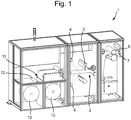
- a tape sectioning system 1 comprises a tape web feed path 2 for feeding a web of fiber reinforced tape 3, in particular fiber reinforced tape, such as unidirectional (UD) tape.
- a quality inspection system 4 for assessing the quality of the web of tape 3 is arranged along the web feed path 2.
- a sectioner 6 is arranged to separate longitudinal tape sections 7 from the web of tape 3. The sectioner 6 is arranged at the end of the tape web feed path 2. The sectioner 6 is further arranged to vary the length of the tape sections 7 that are separated based on the quality of the tape. The sectioner 6 is arranged to vary the length of the tape sections 7 that are separated based on the quality of the tape.
- the quality inspection system 4 assess the quality of the web of tape 3, before it is sectioned into separate tape sections 7 by the sectioner 6. For example, the optical quality, the surface integrity, the thickness, the width, the composition etc. which are features that represent quality aspects of the tape that, if not in accordance with a desired standard, may constitute defects.
- the quality inspection system 4 comprises cameras for visual inspection of the surface quality of a web of tape 3.
- the tape sectioning system 1 further comprises a roll of tape 10.
- the roll of tape 10 is uncoiled by an uncoiling device 11.
- the tape sectioning device 1 is provided with two rolls of tape 10 and a splicer 12 that enables a continuous uncoiling process, which has the added benefit of increasing the throughput of tape in the tape sectioning system 1.
- the tape is uncoiled into a tape web feed path 2 for feeding a web of fiber reinforced tape 3 to the sectioner 6.
- the sectioner 6 for instance cuts with a knife, laser or (water)jet.
- the sectioner 6 can be dynamic or stationary, that is to say moving along with the tape web of not. Varying the length of tape sections 7 in this way can reduce scrap and optimize the use of material. Thereby, the cost efficiency of the manufacturing process can be increased.
- a tape sectioning system 1 comprising a tape web feed path 2 for feeding a web 3 of fiber reinforced tape, and a quality inspection system 4 arranged along the web feed path 2 that inspects the web 3 of tape, in particular for occurrence of defects, as well as a sectioner 6 arranged at the end of the tape web feed path 2 that sections longitudinal tape sections 7 from the web 3 of tape.
- the sectioner 6 is arranged to vary the length of the tape sections 7 that are sectioned off from the web 3 of tape based on the outcome of the quality inspection, in particular based on a difference in presence of defects in the tape sections. Referring to Fig.
- the sectioner 6 of the tape sectioning system 1 is arranged to separate tape sections 7 from the web of tape 3 that are of a first quality, and that are of other quality.
- the tape sections 7 of first quality are cut to a predetermined length L 1 .
- the tape sections 7 of the first quality are of equal predetermined length L 1 .
- the tape sections 7 of other quality include tape sections of different length L than the tape sections 7 of the first quality.
- the tape sectioning system 1 comprises a first discharge path 13 for sections of tape 7 of the first quality, and a further discharge path 14 for sections of tape 7 of other quality.
- the sectioner 6 is arranged to section the tape sections 7 of the first quality at equal predetermined length L 1 .
- An adjustable web feed path length is used here to vary the speed at which tape is fed to the sectioner 6 and to be able to section the tape sections 7 to the desired length, such as the predetermined length L 1 and the different length L.
- the speed of the web feed path 2 can also be varied, for example by providing a brake on the uncoiling device 11 of the tape sectioning system.
- the quality inspection system 4 is arranged for recognizing defects in the tape along the web feed path 2, such that the tape is sectioned before and after the defect by the sectioner 6 downstream of the inspection system 4.
- tape sections 7 of other quality include tape sections 7 that are of smaller length than the tape sections 7 of the first quality.
- the further discharge path 14 of the tape sectioning system 1 comprises a second discharge path 15 for sections of tape 7 of a second quality and a third discharge path 16 for sections of tape 7 of other quality.
- tape sections 7 of a viable quality to be used in the laminated product further reduces scrap material and optimizes material use. Thereby, further increasing the cost efficiency of the manufacturing process.
- sections of tape 7 of a second quality are of equal length as the tape sections 7 of the first quality, i.e. predetermined length L 1 .
- the third discharge path 16 includes tape sections 7 of mutually different quality and mutually different length L. Tape sections 7 of other quality are discarded as scrap. As illustrated in Figs.
- the first discharge path 13 of the tape sectioning system 1 leads to a first buffer 17 arranged for buffering tape sections 7 of mutually equal predetermined length L 1 .
- the second discharge path 15 leads to a second buffer 18 arranged for buffering tape sections 7 of mutually equal predetermined length L 1 .
Landscapes
- Engineering & Computer Science (AREA)
- Mechanical Engineering (AREA)
- Life Sciences & Earth Sciences (AREA)
- General Engineering & Computer Science (AREA)
- Forests & Forestry (AREA)
- Physics & Mathematics (AREA)
- Automation & Control Theory (AREA)
- Computer Vision & Pattern Recognition (AREA)
- General Physics & Mathematics (AREA)
- Quality & Reliability (AREA)
- Manufacturing & Machinery (AREA)
- Chemical & Material Sciences (AREA)
- Composite Materials (AREA)
- Nonwoven Fabrics (AREA)
- Details Of Cutting Devices (AREA)
- Moulding By Coating Moulds (AREA)
Claims (12)
- Bandabschneidesystem (1), umfassend einen Bandbahnzuführweg (2) zum Zuführen einer Bahn aus faserverstärktem Band (3), ein entlang des Bahnzuführweges (2) angeordnetes Qualitätsprüfungssystem (4), das die Qualität der Bandbahn (3) prüft, und einen Abschneider (6), der Längsbandabschnitte (7) von der Bandbahn (3) abschneidet, dadurch gekennzeichnet, dass der Abschneider (6) so angeordnet ist, dass er die Länge der Bandabschnitte (7), die von der Bandbahn (3) abgeteilt werden, basierend auf dem Ergebnis der Qualitätsprüfung verändert, wobei der Abschneider (6) so angeordnet ist, dass er Bandabschnitte (7) von der Bandbahn (3) trennt, die von einer ersten Qualität sind und die von anderer Qualität sind, umfassend einen ersten Ausgabepfad (13) für Bandabschnitte der ersten Qualität und einen weiteren Ausgabepfad (14) für Bandabschnitte anderer Qualität.
- Bandabschneidesystem (1) nach Anspruch 1, wobei die Bandabschnitte der ersten Qualität gleich lang, insbesondere in einer vorbestimmten Länge, sind, und wobei die Bandabschnitte von anderer Qualität Bandabschnitte (7) mit einer anderen Länge als die Bandabschnitte der ersten Qualität umfassen.
- Bandabschneidesystem (1) nach Anspruch 1 oder 2, wobei die Bandabschnitte von anderer Qualität Bandabschnitte (7) umfassen, die von geringerer Länge sind als die Bandabschnitte der ersten Qualität.
- Bandabschneidesystem (1) nach einem der Ansprüche 1 bis 3, wobei der weitere Ausgabepfad (14) einen zweiten Ausgabepfad (15) für Bandabschnitte einer zweiten Qualität und einen dritten Ausgabepfad (16) für Bandabschnitte von anderer Qualität umfasst.
- Bandabschneidesystem (1) nach Anspruch 4, wobei die Bandabschnitte der zweiten Qualität gleich lang sind wie die Bandabschnitte der ersten Qualität.
- Bandabschneidesystem (1) nach Anspruch 5, wobei der dritte Ausgabepfad (16) Bandabschnitte (7) von gegenseitig unterschiedlicher Qualität und gegenseitig unterschiedlicher Länge umfasst.
- Bandabschneidesystem (1) nach einem der Ansprüche 1 bis 6, wobei der erste Ausgabepfad (13) zu einem ersten Puffer (17) führt, der so angeordnet ist, dass er Bandabschnitte (7) mit gegenseitig gleicher Länge puffert, insbesondere einer vorbestimmten Länge.
- Bandabschneidesystem (1) nach einem der Ansprüche 4 bis 7, wobei der zweite Ausgabepfad (14) zu einem zweiten Puffer (18) führt, der so angeordnet ist, dass er Bandabschnitte (7) mit gegenseitig gleicher Länge puffert, insbesondere einer vorbestimmten Länge.
- Verfahren zum Abteilen von Bändern, umfassend das Zuführen einer Bahn aus faserverstärktem Band (3), das Bewerten der Qualität der Bandbahn (3) und das Abteilen von Längsbandabschnitten (7) von der Bandbahn (3), dadurch gekennzeichnet, dass die Länge der Bandabschnitte (7), die von der Bandbahn (3) abgeteilt werden, basierend auf der Bewertung der Qualität der Bandbahn (3) verändert wird, wobei die Bandbahn (3) in Bandabschnitte (7) geteilt wird, die von einer ersten Qualität sind und die von anderer Qualität sind, wobei Bandabschnitte der ersten Qualität über einen ersten Ausgabepfad (13) ausgegeben werden und wobei Bandabschnitte anderer Qualität über einen weiteren Ausgabepfad (14) ausgegeben werden.
- Verfahren nach Anspruch 9, wobei die Bandabschnitte der ersten Qualität gleich lang, insbesondere in einer vorbestimmten Länge, sind, und wobei die Bandabschnitte anderer Qualität Bandabschnitte mit einer anderen Länge als die Bandabschnitte der ersten Qualität umfassen.
- Verfahren nach Anspruch 10, wobei die Bandabschnitte anderer Qualität Bandabschnitte umfassen, die von geringerer Länge sind als die Bandabschnitte der ersten Qualität.
- Verfahren nach einem der Ansprüche 9 bis 11, wobei die Bandbahn (3) ferner in Bandabschnitte (7) von zweiter Qualität geteilt wird, die von gleicher Länge wie die Bandabschnitte von erster Qualität sind.
Applications Claiming Priority (1)
| Application Number | Priority Date | Filing Date | Title |
|---|---|---|---|
| NL2020361A NL2020361B1 (en) | 2018-01-31 | 2018-01-31 | Tape sectioning system and method of sectioning tape |
Publications (2)
| Publication Number | Publication Date |
|---|---|
| EP3520974A1 EP3520974A1 (de) | 2019-08-07 |
| EP3520974B1 true EP3520974B1 (de) | 2020-08-12 |
Family
ID=62598015
Family Applications (1)
| Application Number | Title | Priority Date | Filing Date |
|---|---|---|---|
| EP19154863.5A Active EP3520974B1 (de) | 2018-01-31 | 2019-01-31 | Bandschneidesystem und verfahren zum schneiden eines bandes |
Country Status (6)
| Country | Link |
|---|---|
| US (1) | US11654591B2 (de) |
| EP (1) | EP3520974B1 (de) |
| JP (1) | JP7338939B2 (de) |
| CN (1) | CN111971152A (de) |
| NL (1) | NL2020361B1 (de) |
| WO (1) | WO2019151859A1 (de) |
Families Citing this family (2)
| Publication number | Priority date | Publication date | Assignee | Title |
|---|---|---|---|---|
| CN112536836A (zh) * | 2020-11-19 | 2021-03-23 | 武汉轻工大学 | 切段装置和切段设备 |
| CN120981779A (zh) * | 2023-03-23 | 2025-11-18 | 通快机床欧洲股份公司 | 用于分割加工板类工件的方法和机器组件 |
Family Cites Families (24)
| Publication number | Priority date | Publication date | Assignee | Title |
|---|---|---|---|---|
| US517558A (en) * | 1894-04-03 | Veneer-mortising machine | ||
| US3760667A (en) * | 1969-01-15 | 1973-09-25 | Black Clawson Co | Veneer defect detector and clipper control |
| DE3542923A1 (de) * | 1985-12-04 | 1987-06-11 | Windmoeller & Hoelscher | Vorrichtung zum abtrennen von abschnitten von einer bahn durch quertrennschnitte entsprechend auf der bahn befindlichen druckmarken |
| EP0378052B1 (de) * | 1989-01-13 | 1992-09-30 | SIG Schweizerische Industrie-Gesellschaft | Verpackungsvorrichtung mit einer Beutelformmaschine zum Herstellen von mit Gut zu füllenden Beuteln |
| US4934228A (en) * | 1989-01-13 | 1990-06-19 | U.S. Natural Resources, Inc. | System for diverting veneer sheets having offsize defects |
| DE4209496C2 (de) | 1992-03-24 | 1995-05-04 | Siempelkamp Gmbh & Co | Anlage zum Zusammenlegen von Vorproduktfolien zu Vorprodukteinheiten im Zuge der Herstellung von Laminatplatten |
| WO1993024288A1 (fr) | 1992-05-29 | 1993-12-09 | Tsukishima Kikai Kabushiki Kaisha | Dispositif de distribution automatique destine a un materiau adhesif en feuille |
| JPH0639918Y2 (ja) | 1992-07-09 | 1994-10-19 | 富士写真フイルム株式会社 | ウェブ切断装置 |
| US6520057B1 (en) * | 1997-09-30 | 2003-02-18 | Eastman Machine Company | Continuous system and method for cutting sheet material |
| US8158210B2 (en) * | 2005-10-28 | 2012-04-17 | The Boeing Company | Systems and methods for tape flaw and splice avoidance in manufacturing |
| ATE445872T1 (de) | 2007-02-01 | 2009-10-15 | Abb Oy | Verfahren zur erstellung eines optimierten schnittplans für ein streifenförmiges material |
| JP5399129B2 (ja) | 2009-05-11 | 2014-01-29 | 北川精機株式会社 | 切断装置 |
| EP2730914B1 (de) * | 2011-10-28 | 2016-07-13 | Toray Industries, Inc. | Verfahren zur herstellung von prepreg |
| JP5724152B1 (ja) | 2013-05-17 | 2015-05-27 | 住友化学株式会社 | 光学表示デバイスの生産システム |
| JP2015102376A (ja) | 2013-11-22 | 2015-06-04 | ダックエンジニアリング株式会社 | シート処理方法、及びシート処理システム |
| CN103979148B (zh) * | 2014-05-02 | 2015-10-07 | 常德烟草机械有限责任公司 | 一种用于薄膜分切在线位置调整的控制系统和方法 |
| US9676175B2 (en) | 2014-06-20 | 2017-06-13 | Semiconductor Energy Laboratory Co., Ltd. | Peeling apparatus |
| JP5815909B1 (ja) | 2014-10-10 | 2015-11-17 | 住友化学株式会社 | セパレータ原反の製造方法、セパレータの製造方法、セパレータ原反、及びセパレータ原反製造装置 |
| CN104461682B (zh) | 2014-10-31 | 2017-10-27 | 武汉武钢众鹏信息系统有限公司 | 一种轧钢钢板仿真分切质量判定系统及方法 |
| JP6437329B2 (ja) | 2015-02-03 | 2018-12-12 | 住友化学株式会社 | 光学フィルムの欠陥検査方法 |
| CN104999504B (zh) | 2015-05-29 | 2017-03-15 | 深圳市慧大成智能科技有限公司 | 一种瓦楞纸板尺寸的测量方法及分纸压线控制方法和系统 |
| AR105372A1 (es) | 2015-07-27 | 2017-09-27 | Dow Global Technologies Llc | Laminados elásticos, métodos para su fabricación y artículos que los comprenden |
| CN205067380U (zh) | 2015-10-28 | 2016-03-02 | 江西弘泰电子信息材料有限公司 | 一种可检测质量缺陷的造纸机卷纸系统 |
| CN206594081U (zh) | 2017-03-13 | 2017-10-27 | 玖龙纸业(天津)有限公司 | 一种应用于切纸机的纸病检测装置 |
-
2018
- 2018-01-31 NL NL2020361A patent/NL2020361B1/nl not_active IP Right Cessation
-
2019
- 2019-01-31 CN CN201980011158.XA patent/CN111971152A/zh not_active Withdrawn
- 2019-01-31 EP EP19154863.5A patent/EP3520974B1/de active Active
- 2019-01-31 US US15/733,442 patent/US11654591B2/en active Active
- 2019-01-31 WO PCT/NL2019/050062 patent/WO2019151859A1/en not_active Ceased
- 2019-01-31 JP JP2020541968A patent/JP7338939B2/ja active Active
Non-Patent Citations (1)
| Title |
|---|
| None * |
Also Published As
| Publication number | Publication date |
|---|---|
| JP2021513471A (ja) | 2021-05-27 |
| EP3520974A1 (de) | 2019-08-07 |
| JP7338939B2 (ja) | 2023-09-05 |
| US11654591B2 (en) | 2023-05-23 |
| WO2019151859A1 (en) | 2019-08-08 |
| US20210101302A1 (en) | 2021-04-08 |
| CN111971152A (zh) | 2020-11-20 |
| NL2020361B1 (en) | 2019-08-07 |
Similar Documents
| Publication | Publication Date | Title |
|---|---|---|
| US20120237776A1 (en) | Backed ply material and apparatus for forming same | |
| US9180653B2 (en) | Prepreg production method | |
| US9586390B2 (en) | Prepreg tape slitting method and apparatus | |
| CN104995006B (zh) | 层合体的制造方法 | |
| US10836092B2 (en) | Method for manufacturing a material strand assembly | |
| US20240001627A1 (en) | Thermoplastic Composite Master Sheets and Tapes and Method | |
| JP2013095139A (ja) | 複合充填材を製造する方法及び装置 | |
| US11654591B2 (en) | Tape sectioning system and method of sectioning tape | |
| US10016934B2 (en) | Automated fabrication of composite fillers | |
| JP6935620B2 (ja) | 薄層プリプレグテープの自動積層方法及び装置 | |
| US20130217558A1 (en) | Method and device for producing a semi-finished web and method for producing a composite material | |
| EP3713760B1 (de) | Zwischenmaterial und verfahren zur herstellung solch eines materials | |
| JP2024016302A (ja) | 接続部およびシートモールディングコンパウンドの製造方法 | |
| US11911980B2 (en) | Unidirectionally fiber-reinforced endless winding ply | |
| CN115139570B (zh) | 缠绕纸板管、用于制造其的设备和方法 | |
| CN106064521A (zh) | 用于监测复合叠层机的带端的系统和方法 | |
| US20220410509A1 (en) | Systems for and methods of forming structural components | |
| Nardi et al. | Experimental Investigation of the Effects of Pre-Preg Gaps for the Automated Production of Fiber Metal Laminates | |
| KR20170067991A (ko) | 복합판넬 압출 시스템 | |
| CN117445430A (zh) | 用于复合层压板结构的高速生产的方法和设备 | |
| CA2851680C (en) | Clip ejector | |
| Li et al. | Statistics and Analysis of Manufacturing Defects and Damage of Helicopter Composite Structures |
Legal Events
| Date | Code | Title | Description |
|---|---|---|---|
| PUAI | Public reference made under article 153(3) epc to a published international application that has entered the european phase |
Free format text: ORIGINAL CODE: 0009012 |
|
| STAA | Information on the status of an ep patent application or granted ep patent |
Free format text: STATUS: THE APPLICATION HAS BEEN PUBLISHED |
|
| AK | Designated contracting states |
Kind code of ref document: A1 Designated state(s): AL AT BE BG CH CY CZ DE DK EE ES FI FR GB GR HR HU IE IS IT LI LT LU LV MC MK MT NL NO PL PT RO RS SE SI SK SM TR |
|
| AX | Request for extension of the european patent |
Extension state: BA ME |
|
| STAA | Information on the status of an ep patent application or granted ep patent |
Free format text: STATUS: REQUEST FOR EXAMINATION WAS MADE |
|
| 17P | Request for examination filed |
Effective date: 20190814 |
|
| RBV | Designated contracting states (corrected) |
Designated state(s): AL AT BE BG CH CY CZ DE DK EE ES FI FR GB GR HR HU IE IS IT LI LT LU LV MC MK MT NL NO PL PT RO RS SE SI SK SM TR |
|
| GRAP | Despatch of communication of intention to grant a patent |
Free format text: ORIGINAL CODE: EPIDOSNIGR1 |
|
| STAA | Information on the status of an ep patent application or granted ep patent |
Free format text: STATUS: GRANT OF PATENT IS INTENDED |
|
| INTG | Intention to grant announced |
Effective date: 20200213 |
|
| GRAS | Grant fee paid |
Free format text: ORIGINAL CODE: EPIDOSNIGR3 |
|
| GRAA | (expected) grant |
Free format text: ORIGINAL CODE: 0009210 |
|
| STAA | Information on the status of an ep patent application or granted ep patent |
Free format text: STATUS: THE PATENT HAS BEEN GRANTED |
|
| AK | Designated contracting states |
Kind code of ref document: B1 Designated state(s): AL AT BE BG CH CY CZ DE DK EE ES FI FR GB GR HR HU IE IS IT LI LT LU LV MC MK MT NL NO PL PT RO RS SE SI SK SM TR |
|
| REG | Reference to a national code |
Ref country code: CH Ref legal event code: EP |
|
| REG | Reference to a national code |
Ref country code: CH Ref legal event code: PK Free format text: BERICHTIGUNGEN |
|
| REG | Reference to a national code |
Ref country code: IE Ref legal event code: FG4D |
|
| REG | Reference to a national code |
Ref country code: DE Ref legal event code: R096 Ref document number: 602019000428 Country of ref document: DE |
|
| REG | Reference to a national code |
Ref country code: AT Ref legal event code: REF Ref document number: 1301104 Country of ref document: AT Kind code of ref document: T Effective date: 20200915 |
|
| RAP2 | Party data changed (patent owner data changed or rights of a patent transferred) |
Owner name: AIRBORNE INTERNATIONAL B.V. |
|
| RIN2 | Information on inventor provided after grant (corrected) |
Inventor name: MUILWIJK, MARK Inventor name: VAN OVERBEEK, THOMAS THEODORUS ARNOLDUS Inventor name: BROEDSJOE, ANDERS |
|
| REG | Reference to a national code |
Ref country code: NL Ref legal event code: FP |
|
| REG | Reference to a national code |
Ref country code: LT Ref legal event code: MG4D |
|
| PG25 | Lapsed in a contracting state [announced via postgrant information from national office to epo] |
Ref country code: SE Free format text: LAPSE BECAUSE OF FAILURE TO SUBMIT A TRANSLATION OF THE DESCRIPTION OR TO PAY THE FEE WITHIN THE PRESCRIBED TIME-LIMIT Effective date: 20200812 Ref country code: FI Free format text: LAPSE BECAUSE OF FAILURE TO SUBMIT A TRANSLATION OF THE DESCRIPTION OR TO PAY THE FEE WITHIN THE PRESCRIBED TIME-LIMIT Effective date: 20200812 Ref country code: NO Free format text: LAPSE BECAUSE OF FAILURE TO SUBMIT A TRANSLATION OF THE DESCRIPTION OR TO PAY THE FEE WITHIN THE PRESCRIBED TIME-LIMIT Effective date: 20201112 Ref country code: GR Free format text: LAPSE BECAUSE OF FAILURE TO SUBMIT A TRANSLATION OF THE DESCRIPTION OR TO PAY THE FEE WITHIN THE PRESCRIBED TIME-LIMIT Effective date: 20201113 Ref country code: LT Free format text: LAPSE BECAUSE OF FAILURE TO SUBMIT A TRANSLATION OF THE DESCRIPTION OR TO PAY THE FEE WITHIN THE PRESCRIBED TIME-LIMIT Effective date: 20200812 Ref country code: HR Free format text: LAPSE BECAUSE OF FAILURE TO SUBMIT A TRANSLATION OF THE DESCRIPTION OR TO PAY THE FEE WITHIN THE PRESCRIBED TIME-LIMIT Effective date: 20200812 Ref country code: BG Free format text: LAPSE BECAUSE OF FAILURE TO SUBMIT A TRANSLATION OF THE DESCRIPTION OR TO PAY THE FEE WITHIN THE PRESCRIBED TIME-LIMIT Effective date: 20201112 |
|
| REG | Reference to a national code |
Ref country code: AT Ref legal event code: MK05 Ref document number: 1301104 Country of ref document: AT Kind code of ref document: T Effective date: 20200812 |
|
| PG25 | Lapsed in a contracting state [announced via postgrant information from national office to epo] |
Ref country code: LV Free format text: LAPSE BECAUSE OF FAILURE TO SUBMIT A TRANSLATION OF THE DESCRIPTION OR TO PAY THE FEE WITHIN THE PRESCRIBED TIME-LIMIT Effective date: 20200812 Ref country code: PL Free format text: LAPSE BECAUSE OF FAILURE TO SUBMIT A TRANSLATION OF THE DESCRIPTION OR TO PAY THE FEE WITHIN THE PRESCRIBED TIME-LIMIT Effective date: 20200812 Ref country code: RS Free format text: LAPSE BECAUSE OF FAILURE TO SUBMIT A TRANSLATION OF THE DESCRIPTION OR TO PAY THE FEE WITHIN THE PRESCRIBED TIME-LIMIT Effective date: 20200812 Ref country code: IS Free format text: LAPSE BECAUSE OF FAILURE TO SUBMIT A TRANSLATION OF THE DESCRIPTION OR TO PAY THE FEE WITHIN THE PRESCRIBED TIME-LIMIT Effective date: 20201212 |
|
| PG25 | Lapsed in a contracting state [announced via postgrant information from national office to epo] |
Ref country code: SM Free format text: LAPSE BECAUSE OF FAILURE TO SUBMIT A TRANSLATION OF THE DESCRIPTION OR TO PAY THE FEE WITHIN THE PRESCRIBED TIME-LIMIT Effective date: 20200812 Ref country code: RO Free format text: LAPSE BECAUSE OF FAILURE TO SUBMIT A TRANSLATION OF THE DESCRIPTION OR TO PAY THE FEE WITHIN THE PRESCRIBED TIME-LIMIT Effective date: 20200812 Ref country code: CZ Free format text: LAPSE BECAUSE OF FAILURE TO SUBMIT A TRANSLATION OF THE DESCRIPTION OR TO PAY THE FEE WITHIN THE PRESCRIBED TIME-LIMIT Effective date: 20200812 Ref country code: DK Free format text: LAPSE BECAUSE OF FAILURE TO SUBMIT A TRANSLATION OF THE DESCRIPTION OR TO PAY THE FEE WITHIN THE PRESCRIBED TIME-LIMIT Effective date: 20200812 Ref country code: EE Free format text: LAPSE BECAUSE OF FAILURE TO SUBMIT A TRANSLATION OF THE DESCRIPTION OR TO PAY THE FEE WITHIN THE PRESCRIBED TIME-LIMIT Effective date: 20200812 |
|
| REG | Reference to a national code |
Ref country code: DE Ref legal event code: R097 Ref document number: 602019000428 Country of ref document: DE |
|
| PG25 | Lapsed in a contracting state [announced via postgrant information from national office to epo] |
Ref country code: AT Free format text: LAPSE BECAUSE OF FAILURE TO SUBMIT A TRANSLATION OF THE DESCRIPTION OR TO PAY THE FEE WITHIN THE PRESCRIBED TIME-LIMIT Effective date: 20200812 Ref country code: AL Free format text: LAPSE BECAUSE OF FAILURE TO SUBMIT A TRANSLATION OF THE DESCRIPTION OR TO PAY THE FEE WITHIN THE PRESCRIBED TIME-LIMIT Effective date: 20200812 Ref country code: ES Free format text: LAPSE BECAUSE OF FAILURE TO SUBMIT A TRANSLATION OF THE DESCRIPTION OR TO PAY THE FEE WITHIN THE PRESCRIBED TIME-LIMIT Effective date: 20200812 |
|
| PLBE | No opposition filed within time limit |
Free format text: ORIGINAL CODE: 0009261 |
|
| STAA | Information on the status of an ep patent application or granted ep patent |
Free format text: STATUS: NO OPPOSITION FILED WITHIN TIME LIMIT |
|
| PG25 | Lapsed in a contracting state [announced via postgrant information from national office to epo] |
Ref country code: SK Free format text: LAPSE BECAUSE OF FAILURE TO SUBMIT A TRANSLATION OF THE DESCRIPTION OR TO PAY THE FEE WITHIN THE PRESCRIBED TIME-LIMIT Effective date: 20200812 |
|
| 26N | No opposition filed |
Effective date: 20210514 |
|
| PG25 | Lapsed in a contracting state [announced via postgrant information from national office to epo] |
Ref country code: IT Free format text: LAPSE BECAUSE OF FAILURE TO SUBMIT A TRANSLATION OF THE DESCRIPTION OR TO PAY THE FEE WITHIN THE PRESCRIBED TIME-LIMIT Effective date: 20200812 |
|
| PG25 | Lapsed in a contracting state [announced via postgrant information from national office to epo] |
Ref country code: MC Free format text: LAPSE BECAUSE OF FAILURE TO SUBMIT A TRANSLATION OF THE DESCRIPTION OR TO PAY THE FEE WITHIN THE PRESCRIBED TIME-LIMIT Effective date: 20200812 Ref country code: SI Free format text: LAPSE BECAUSE OF FAILURE TO SUBMIT A TRANSLATION OF THE DESCRIPTION OR TO PAY THE FEE WITHIN THE PRESCRIBED TIME-LIMIT Effective date: 20200812 |
|
| PG25 | Lapsed in a contracting state [announced via postgrant information from national office to epo] |
Ref country code: LU Free format text: LAPSE BECAUSE OF NON-PAYMENT OF DUE FEES Effective date: 20210131 |
|
| REG | Reference to a national code |
Ref country code: BE Ref legal event code: MM Effective date: 20210131 |
|
| PG25 | Lapsed in a contracting state [announced via postgrant information from national office to epo] |
Ref country code: IE Free format text: LAPSE BECAUSE OF NON-PAYMENT OF DUE FEES Effective date: 20210131 |
|
| PG25 | Lapsed in a contracting state [announced via postgrant information from national office to epo] |
Ref country code: BE Free format text: LAPSE BECAUSE OF NON-PAYMENT OF DUE FEES Effective date: 20210131 |
|
| REG | Reference to a national code |
Ref country code: CH Ref legal event code: PL |
|
| PG25 | Lapsed in a contracting state [announced via postgrant information from national office to epo] |
Ref country code: LI Free format text: LAPSE BECAUSE OF NON-PAYMENT OF DUE FEES Effective date: 20220131 Ref country code: CH Free format text: LAPSE BECAUSE OF NON-PAYMENT OF DUE FEES Effective date: 20220131 |
|
| PG25 | Lapsed in a contracting state [announced via postgrant information from national office to epo] |
Ref country code: PT Free format text: LAPSE BECAUSE OF FAILURE TO SUBMIT A TRANSLATION OF THE DESCRIPTION OR TO PAY THE FEE WITHIN THE PRESCRIBED TIME-LIMIT Effective date: 20201214 |
|
| PG25 | Lapsed in a contracting state [announced via postgrant information from national office to epo] |
Ref country code: CY Free format text: LAPSE BECAUSE OF FAILURE TO SUBMIT A TRANSLATION OF THE DESCRIPTION OR TO PAY THE FEE WITHIN THE PRESCRIBED TIME-LIMIT Effective date: 20200812 |
|
| PG25 | Lapsed in a contracting state [announced via postgrant information from national office to epo] |
Ref country code: HU Free format text: LAPSE BECAUSE OF FAILURE TO SUBMIT A TRANSLATION OF THE DESCRIPTION OR TO PAY THE FEE WITHIN THE PRESCRIBED TIME-LIMIT; INVALID AB INITIO Effective date: 20190131 |
|
| PG25 | Lapsed in a contracting state [announced via postgrant information from national office to epo] |
Ref country code: MK Free format text: LAPSE BECAUSE OF FAILURE TO SUBMIT A TRANSLATION OF THE DESCRIPTION OR TO PAY THE FEE WITHIN THE PRESCRIBED TIME-LIMIT Effective date: 20200812 |
|
| PG25 | Lapsed in a contracting state [announced via postgrant information from national office to epo] |
Ref country code: TR Free format text: LAPSE BECAUSE OF FAILURE TO SUBMIT A TRANSLATION OF THE DESCRIPTION OR TO PAY THE FEE WITHIN THE PRESCRIBED TIME-LIMIT Effective date: 20200812 |
|
| PG25 | Lapsed in a contracting state [announced via postgrant information from national office to epo] |
Ref country code: MT Free format text: LAPSE BECAUSE OF FAILURE TO SUBMIT A TRANSLATION OF THE DESCRIPTION OR TO PAY THE FEE WITHIN THE PRESCRIBED TIME-LIMIT Effective date: 20200812 |
|
| PGFP | Annual fee paid to national office [announced via postgrant information from national office to epo] |
Ref country code: NL Payment date: 20260121 Year of fee payment: 8 |
|
| PGFP | Annual fee paid to national office [announced via postgrant information from national office to epo] |
Ref country code: GB Payment date: 20260123 Year of fee payment: 8 |
|
| PGFP | Annual fee paid to national office [announced via postgrant information from national office to epo] |
Ref country code: DE Payment date: 20260121 Year of fee payment: 8 |
|
| PGFP | Annual fee paid to national office [announced via postgrant information from national office to epo] |
Ref country code: FR Payment date: 20260123 Year of fee payment: 8 |