EP3517652A1 - Procédé de production de feuille métallique perforée - Google Patents
Procédé de production de feuille métallique perforée Download PDFInfo
- Publication number
- EP3517652A1 EP3517652A1 EP17852750.3A EP17852750A EP3517652A1 EP 3517652 A1 EP3517652 A1 EP 3517652A1 EP 17852750 A EP17852750 A EP 17852750A EP 3517652 A1 EP3517652 A1 EP 3517652A1
- Authority
- EP
- European Patent Office
- Prior art keywords
- foil
- resin layer
- metal foil
- particles
- forming step
- Prior art date
- Legal status (The legal status is an assumption and is not a legal conclusion. Google has not performed a legal analysis and makes no representation as to the accuracy of the status listed.)
- Withdrawn
Links
- 239000011888 foil Substances 0.000 title claims abstract description 314
- 229910052751 metal Inorganic materials 0.000 title claims abstract description 264
- 239000002184 metal Substances 0.000 title claims abstract description 264
- 238000004519 manufacturing process Methods 0.000 title claims abstract description 92
- 229920005989 resin Polymers 0.000 claims abstract description 315
- 239000011347 resin Substances 0.000 claims abstract description 315
- 239000000203 mixture Substances 0.000 claims abstract description 87
- 239000002923 metal particle Substances 0.000 claims abstract description 61
- 229920000642 polymer Polymers 0.000 claims abstract description 58
- 239000010410 layer Substances 0.000 claims description 264
- 239000002245 particle Substances 0.000 claims description 152
- RYGMFSIKBFXOCR-UHFFFAOYSA-N Copper Chemical compound [Cu] RYGMFSIKBFXOCR-UHFFFAOYSA-N 0.000 claims description 100
- 239000011889 copper foil Substances 0.000 claims description 66
- 239000011241 protective layer Substances 0.000 claims description 62
- PXHVJJICTQNCMI-UHFFFAOYSA-N Nickel Chemical compound [Ni] PXHVJJICTQNCMI-UHFFFAOYSA-N 0.000 claims description 42
- 229910052782 aluminium Inorganic materials 0.000 claims description 32
- XAGFODPZIPBFFR-UHFFFAOYSA-N aluminium Chemical compound [Al] XAGFODPZIPBFFR-UHFFFAOYSA-N 0.000 claims description 32
- 239000000463 material Substances 0.000 claims description 17
- 230000005484 gravity Effects 0.000 claims description 16
- 239000010935 stainless steel Substances 0.000 claims description 16
- 229910001220 stainless steel Inorganic materials 0.000 claims description 16
- 239000002904 solvent Substances 0.000 claims description 15
- 229910045601 alloy Inorganic materials 0.000 claims description 10
- 239000000956 alloy Substances 0.000 claims description 10
- XEEYBQQBJWHFJM-UHFFFAOYSA-N Iron Chemical compound [Fe] XEEYBQQBJWHFJM-UHFFFAOYSA-N 0.000 claims description 7
- 239000004925 Acrylic resin Substances 0.000 claims description 6
- 229920000178 Acrylic resin Polymers 0.000 claims description 6
- 239000004642 Polyimide Substances 0.000 claims description 5
- BASFCYQUMIYNBI-UHFFFAOYSA-N platinum Chemical compound [Pt] BASFCYQUMIYNBI-UHFFFAOYSA-N 0.000 claims description 5
- 229920001721 polyimide Polymers 0.000 claims description 5
- ZOKXTWBITQBERF-UHFFFAOYSA-N Molybdenum Chemical compound [Mo] ZOKXTWBITQBERF-UHFFFAOYSA-N 0.000 claims description 4
- BQCADISMDOOEFD-UHFFFAOYSA-N Silver Chemical compound [Ag] BQCADISMDOOEFD-UHFFFAOYSA-N 0.000 claims description 4
- ATJFFYVFTNAWJD-UHFFFAOYSA-N Tin Chemical compound [Sn] ATJFFYVFTNAWJD-UHFFFAOYSA-N 0.000 claims description 4
- RTAQQCXQSZGOHL-UHFFFAOYSA-N Titanium Chemical compound [Ti] RTAQQCXQSZGOHL-UHFFFAOYSA-N 0.000 claims description 4
- HCHKCACWOHOZIP-UHFFFAOYSA-N Zinc Chemical compound [Zn] HCHKCACWOHOZIP-UHFFFAOYSA-N 0.000 claims description 4
- QCWXUUIWCKQGHC-UHFFFAOYSA-N Zirconium Chemical compound [Zr] QCWXUUIWCKQGHC-UHFFFAOYSA-N 0.000 claims description 4
- QHIWVLPBUQWDMQ-UHFFFAOYSA-N butyl prop-2-enoate;methyl 2-methylprop-2-enoate;prop-2-enoic acid Chemical compound OC(=O)C=C.COC(=O)C(C)=C.CCCCOC(=O)C=C QHIWVLPBUQWDMQ-UHFFFAOYSA-N 0.000 claims description 4
- PCHJSUWPFVWCPO-UHFFFAOYSA-N gold Chemical compound [Au] PCHJSUWPFVWCPO-UHFFFAOYSA-N 0.000 claims description 4
- 229910052750 molybdenum Inorganic materials 0.000 claims description 4
- 239000011733 molybdenum Substances 0.000 claims description 4
- GUCVJGMIXFAOAE-UHFFFAOYSA-N niobium atom Chemical compound [Nb] GUCVJGMIXFAOAE-UHFFFAOYSA-N 0.000 claims description 4
- 229920001568 phenolic resin Polymers 0.000 claims description 4
- 239000005011 phenolic resin Substances 0.000 claims description 4
- GUVRBAGPIYLISA-UHFFFAOYSA-N tantalum atom Chemical compound [Ta] GUVRBAGPIYLISA-UHFFFAOYSA-N 0.000 claims description 4
- WFKWXMTUELFFGS-UHFFFAOYSA-N tungsten Chemical compound [W] WFKWXMTUELFFGS-UHFFFAOYSA-N 0.000 claims description 4
- 229910052721 tungsten Inorganic materials 0.000 claims description 4
- 239000010937 tungsten Substances 0.000 claims description 4
- 229910001369 Brass Inorganic materials 0.000 claims description 3
- 229910000906 Bronze Inorganic materials 0.000 claims description 3
- 229910000792 Monel Inorganic materials 0.000 claims description 3
- OAICVXFJPJFONN-UHFFFAOYSA-N Phosphorus Chemical compound [P] OAICVXFJPJFONN-UHFFFAOYSA-N 0.000 claims description 3
- DMFGNRRURHSENX-UHFFFAOYSA-N beryllium copper Chemical compound [Be].[Cu] DMFGNRRURHSENX-UHFFFAOYSA-N 0.000 claims description 3
- 239000010951 brass Substances 0.000 claims description 3
- 239000010974 bronze Substances 0.000 claims description 3
- KUNSUQLRTQLHQQ-UHFFFAOYSA-N copper tin Chemical compound [Cu].[Sn] KUNSUQLRTQLHQQ-UHFFFAOYSA-N 0.000 claims description 3
- 229910000856 hastalloy Inorganic materials 0.000 claims description 3
- 229910001026 inconel Inorganic materials 0.000 claims description 3
- 229910000833 kovar Inorganic materials 0.000 claims description 3
- 229910001120 nichrome Inorganic materials 0.000 claims description 3
- MOFOBJHOKRNACT-UHFFFAOYSA-N nickel silver Chemical compound [Ni].[Ag] MOFOBJHOKRNACT-UHFFFAOYSA-N 0.000 claims description 3
- 239000010956 nickel silver Substances 0.000 claims description 3
- 229910000889 permalloy Inorganic materials 0.000 claims description 3
- 229910000679 solder Inorganic materials 0.000 claims description 3
- 238000010030 laminating Methods 0.000 claims description 2
- 238000000034 method Methods 0.000 abstract description 45
- 239000010949 copper Substances 0.000 description 43
- ZWEHNKRNPOVVGH-UHFFFAOYSA-N 2-Butanone Chemical compound CCC(C)=O ZWEHNKRNPOVVGH-UHFFFAOYSA-N 0.000 description 42
- 229910052802 copper Inorganic materials 0.000 description 37
- 239000011254 layer-forming composition Substances 0.000 description 36
- 238000011282 treatment Methods 0.000 description 30
- ARXJGSRGQADJSQ-UHFFFAOYSA-N 1-methoxypropan-2-ol Chemical compound COCC(C)O ARXJGSRGQADJSQ-UHFFFAOYSA-N 0.000 description 26
- VYPSYNLAJGMNEJ-UHFFFAOYSA-N Silicium dioxide Chemical compound O=[Si]=O VYPSYNLAJGMNEJ-UHFFFAOYSA-N 0.000 description 26
- XLYOFNOQVPJJNP-UHFFFAOYSA-N water Substances O XLYOFNOQVPJJNP-UHFFFAOYSA-N 0.000 description 26
- VEXZGXHMUGYJMC-UHFFFAOYSA-N Hydrochloric acid Chemical compound Cl VEXZGXHMUGYJMC-UHFFFAOYSA-N 0.000 description 19
- -1 polyethylene Polymers 0.000 description 19
- 150000001875 compounds Chemical class 0.000 description 18
- 238000005507 spraying Methods 0.000 description 16
- 230000002378 acidificating effect Effects 0.000 description 15
- 239000004094 surface-active agent Substances 0.000 description 15
- ORTQZVOHEJQUHG-UHFFFAOYSA-L copper(II) chloride Chemical compound Cl[Cu]Cl ORTQZVOHEJQUHG-UHFFFAOYSA-L 0.000 description 14
- 229920003169 water-soluble polymer Polymers 0.000 description 14
- 229920001577 copolymer Polymers 0.000 description 13
- HEMHJVSKTPXQMS-UHFFFAOYSA-M Sodium hydroxide Chemical compound [OH-].[Na+] HEMHJVSKTPXQMS-UHFFFAOYSA-M 0.000 description 12
- 239000011149 active material Substances 0.000 description 12
- 229910052759 nickel Inorganic materials 0.000 description 12
- 239000007864 aqueous solution Substances 0.000 description 11
- 238000007654 immersion Methods 0.000 description 11
- 238000003860 storage Methods 0.000 description 11
- SOGAXMICEFXMKE-UHFFFAOYSA-N Butylmethacrylate Chemical compound CCCCOC(=O)C(C)=C SOGAXMICEFXMKE-UHFFFAOYSA-N 0.000 description 10
- IWDCLRJOBJJRNH-UHFFFAOYSA-N p-cresol Chemical compound CC1=CC=C(O)C=C1 IWDCLRJOBJJRNH-UHFFFAOYSA-N 0.000 description 10
- VZSRBBMJRBPUNF-UHFFFAOYSA-N 2-(2,3-dihydro-1H-inden-2-ylamino)-N-[3-oxo-3-(2,4,6,7-tetrahydrotriazolo[4,5-c]pyridin-5-yl)propyl]pyrimidine-5-carboxamide Chemical compound C1C(CC2=CC=CC=C12)NC1=NC=C(C=N1)C(=O)NCCC(N1CC2=C(CC1)NN=N2)=O VZSRBBMJRBPUNF-UHFFFAOYSA-N 0.000 description 9
- ISWSIDIOOBJBQZ-UHFFFAOYSA-N phenol group Chemical group C1(=CC=CC=C1)O ISWSIDIOOBJBQZ-UHFFFAOYSA-N 0.000 description 9
- 238000005530 etching Methods 0.000 description 8
- 239000007788 liquid Substances 0.000 description 8
- 239000000843 powder Substances 0.000 description 7
- 229910021592 Copper(II) chloride Inorganic materials 0.000 description 6
- 229910019142 PO4 Inorganic materials 0.000 description 6
- KWYUFKZDYYNOTN-UHFFFAOYSA-M Potassium hydroxide Chemical compound [OH-].[K+] KWYUFKZDYYNOTN-UHFFFAOYSA-M 0.000 description 6
- 125000004429 atom Chemical group 0.000 description 6
- 125000003178 carboxy group Chemical group [H]OC(*)=O 0.000 description 6
- 239000002131 composite material Substances 0.000 description 6
- 229920003986 novolac Polymers 0.000 description 6
- 239000013500 performance material Substances 0.000 description 6
- 235000021317 phosphate Nutrition 0.000 description 6
- 150000003852 triazoles Chemical class 0.000 description 6
- FUGYGGDSWSUORM-UHFFFAOYSA-N 4-hydroxystyrene Chemical compound OC1=CC=C(C=C)C=C1 FUGYGGDSWSUORM-UHFFFAOYSA-N 0.000 description 5
- 238000000576 coating method Methods 0.000 description 5
- 238000007334 copolymerization reaction Methods 0.000 description 5
- SUPCQIBBMFXVTL-UHFFFAOYSA-N ethyl 2-methylprop-2-enoate Chemical compound CCOC(=O)C(C)=C SUPCQIBBMFXVTL-UHFFFAOYSA-N 0.000 description 5
- 125000005462 imide group Chemical group 0.000 description 5
- 150000002736 metal compounds Chemical class 0.000 description 5
- JESXATFQYMPTNL-UHFFFAOYSA-N mono-hydroxyphenyl-ethylene Natural products OC1=CC=CC=C1C=C JESXATFQYMPTNL-UHFFFAOYSA-N 0.000 description 5
- 238000007747 plating Methods 0.000 description 5
- 239000000243 solution Substances 0.000 description 5
- 125000000565 sulfonamide group Chemical group 0.000 description 5
- VTYYLEPIZMXCLO-UHFFFAOYSA-L Calcium carbonate Chemical compound [Ca+2].[O-]C([O-])=O VTYYLEPIZMXCLO-UHFFFAOYSA-L 0.000 description 4
- OKTJSMMVPCPJKN-UHFFFAOYSA-N Carbon Chemical compound [C] OKTJSMMVPCPJKN-UHFFFAOYSA-N 0.000 description 4
- CSNNHWWHGAXBCP-UHFFFAOYSA-L Magnesium sulfate Chemical compound [Mg+2].[O-][S+2]([O-])([O-])[O-] CSNNHWWHGAXBCP-UHFFFAOYSA-L 0.000 description 4
- CDBYLPFSWZWCQE-UHFFFAOYSA-L Sodium Carbonate Chemical compound [Na+].[Na+].[O-]C([O-])=O CDBYLPFSWZWCQE-UHFFFAOYSA-L 0.000 description 4
- 239000004115 Sodium Silicate Substances 0.000 description 4
- 229910052783 alkali metal Inorganic materials 0.000 description 4
- OSGAYBCDTDRGGQ-UHFFFAOYSA-L calcium sulfate Chemical compound [Ca+2].[O-]S([O-])(=O)=O OSGAYBCDTDRGGQ-UHFFFAOYSA-L 0.000 description 4
- RBTARNINKXHZNM-UHFFFAOYSA-K iron trichloride Chemical compound Cl[Fe](Cl)Cl RBTARNINKXHZNM-UHFFFAOYSA-K 0.000 description 4
- 150000002739 metals Chemical class 0.000 description 4
- 229920003145 methacrylic acid copolymer Polymers 0.000 description 4
- 239000010452 phosphate Substances 0.000 description 4
- 125000002467 phosphate group Chemical group [H]OP(=O)(O[H])O[*] 0.000 description 4
- 239000007774 positive electrode material Substances 0.000 description 4
- 235000011121 sodium hydroxide Nutrition 0.000 description 4
- NTHWMYGWWRZVTN-UHFFFAOYSA-N sodium silicate Chemical compound [Na+].[Na+].[O-][Si]([O-])=O NTHWMYGWWRZVTN-UHFFFAOYSA-N 0.000 description 4
- 229910052911 sodium silicate Inorganic materials 0.000 description 4
- 239000007787 solid Substances 0.000 description 4
- 238000005406 washing Methods 0.000 description 4
- XLLXMBCBJGATSP-UHFFFAOYSA-N 2-phenylethenol Chemical compound OC=CC1=CC=CC=C1 XLLXMBCBJGATSP-UHFFFAOYSA-N 0.000 description 3
- QTBSBXVTEAMEQO-UHFFFAOYSA-N Acetic acid Chemical compound CC(O)=O QTBSBXVTEAMEQO-UHFFFAOYSA-N 0.000 description 3
- LFQSCWFLJHTTHZ-UHFFFAOYSA-N Ethanol Chemical compound CCO LFQSCWFLJHTTHZ-UHFFFAOYSA-N 0.000 description 3
- WSFSSNUMVMOOMR-UHFFFAOYSA-N Formaldehyde Chemical compound O=C WSFSSNUMVMOOMR-UHFFFAOYSA-N 0.000 description 3
- HBBGRARXTFLTSG-UHFFFAOYSA-N Lithium ion Chemical compound [Li+] HBBGRARXTFLTSG-UHFFFAOYSA-N 0.000 description 3
- OKKJLVBELUTLKV-UHFFFAOYSA-N Methanol Chemical compound OC OKKJLVBELUTLKV-UHFFFAOYSA-N 0.000 description 3
- ZMXDDKWLCZADIW-UHFFFAOYSA-N N,N-Dimethylformamide Chemical compound CN(C)C=O ZMXDDKWLCZADIW-UHFFFAOYSA-N 0.000 description 3
- YXFVVABEGXRONW-UHFFFAOYSA-N Toluene Chemical compound CC1=CC=CC=C1 YXFVVABEGXRONW-UHFFFAOYSA-N 0.000 description 3
- ZMANZCXQSJIPKH-UHFFFAOYSA-N Triethylamine Chemical compound CCN(CC)CC ZMANZCXQSJIPKH-UHFFFAOYSA-N 0.000 description 3
- 239000002253 acid Substances 0.000 description 3
- OJMOMXZKOWKUTA-UHFFFAOYSA-N aluminum;borate Chemical compound [Al+3].[O-]B([O-])[O-] OJMOMXZKOWKUTA-UHFFFAOYSA-N 0.000 description 3
- 230000015572 biosynthetic process Effects 0.000 description 3
- 239000003990 capacitor Substances 0.000 description 3
- 239000011256 inorganic filler Substances 0.000 description 3
- 229910003475 inorganic filler Inorganic materials 0.000 description 3
- 229910001416 lithium ion Inorganic materials 0.000 description 3
- FQPSGWSUVKBHSU-UHFFFAOYSA-N methacrylamide Chemical compound CC(=C)C(N)=O FQPSGWSUVKBHSU-UHFFFAOYSA-N 0.000 description 3
- 230000003287 optical effect Effects 0.000 description 3
- 238000012545 processing Methods 0.000 description 3
- 239000007921 spray Substances 0.000 description 3
- 125000000020 sulfo group Chemical group O=S(=O)([*])O[H] 0.000 description 3
- 230000000007 visual effect Effects 0.000 description 3
- YIWGJFPJRAEKMK-UHFFFAOYSA-N 1-(2H-benzotriazol-5-yl)-3-methyl-8-[2-[[3-(trifluoromethoxy)phenyl]methylamino]pyrimidine-5-carbonyl]-1,3,8-triazaspiro[4.5]decane-2,4-dione Chemical compound CN1C(=O)N(c2ccc3n[nH]nc3c2)C2(CCN(CC2)C(=O)c2cnc(NCc3cccc(OC(F)(F)F)c3)nc2)C1=O YIWGJFPJRAEKMK-UHFFFAOYSA-N 0.000 description 2
- UZKWTJUDCOPSNM-UHFFFAOYSA-N 1-ethenoxybutane Chemical compound CCCCOC=C UZKWTJUDCOPSNM-UHFFFAOYSA-N 0.000 description 2
- JLIDVCMBCGBIEY-UHFFFAOYSA-N 1-penten-3-one Chemical compound CCC(=O)C=C JLIDVCMBCGBIEY-UHFFFAOYSA-N 0.000 description 2
- XLLIQLLCWZCATF-UHFFFAOYSA-N 2-methoxyethyl acetate Chemical compound COCCOC(C)=O XLLIQLLCWZCATF-UHFFFAOYSA-N 0.000 description 2
- YLZOPXRUQYQQID-UHFFFAOYSA-N 3-(2,4,6,7-tetrahydrotriazolo[4,5-c]pyridin-5-yl)-1-[4-[2-[[3-(trifluoromethoxy)phenyl]methylamino]pyrimidin-5-yl]piperazin-1-yl]propan-1-one Chemical compound N1N=NC=2CN(CCC=21)CCC(=O)N1CCN(CC1)C=1C=NC(=NC=1)NCC1=CC(=CC=C1)OC(F)(F)F YLZOPXRUQYQQID-UHFFFAOYSA-N 0.000 description 2
- YEJRWHAVMIAJKC-UHFFFAOYSA-N 4-Butyrolactone Chemical compound O=C1CCCO1 YEJRWHAVMIAJKC-UHFFFAOYSA-N 0.000 description 2
- CMGDVUCDZOBDNL-UHFFFAOYSA-N 4-methyl-2h-benzotriazole Chemical compound CC1=CC=CC2=NNN=C12 CMGDVUCDZOBDNL-UHFFFAOYSA-N 0.000 description 2
- DEXFNLNNUZKHNO-UHFFFAOYSA-N 6-[3-[4-[2-(2,3-dihydro-1H-inden-2-ylamino)pyrimidin-5-yl]piperidin-1-yl]-3-oxopropyl]-3H-1,3-benzoxazol-2-one Chemical compound C1C(CC2=CC=CC=C12)NC1=NC=C(C=N1)C1CCN(CC1)C(CCC1=CC2=C(NC(O2)=O)C=C1)=O DEXFNLNNUZKHNO-UHFFFAOYSA-N 0.000 description 2
- CSCPPACGZOOCGX-UHFFFAOYSA-N Acetone Chemical compound CC(C)=O CSCPPACGZOOCGX-UHFFFAOYSA-N 0.000 description 2
- HRPVXLWXLXDGHG-UHFFFAOYSA-N Acrylamide Chemical compound NC(=O)C=C HRPVXLWXLXDGHG-UHFFFAOYSA-N 0.000 description 2
- KAKZBPTYRLMSJV-UHFFFAOYSA-N Butadiene Chemical compound C=CC=C KAKZBPTYRLMSJV-UHFFFAOYSA-N 0.000 description 2
- 102000053602 DNA Human genes 0.000 description 2
- 108020004414 DNA Proteins 0.000 description 2
- IAZDPXIOMUYVGZ-UHFFFAOYSA-N Dimethylsulphoxide Chemical compound CS(C)=O IAZDPXIOMUYVGZ-UHFFFAOYSA-N 0.000 description 2
- QUSNBJAOOMFDIB-UHFFFAOYSA-N Ethylamine Chemical compound CCN QUSNBJAOOMFDIB-UHFFFAOYSA-N 0.000 description 2
- KRHYYFGTRYWZRS-UHFFFAOYSA-N Fluorane Chemical compound F KRHYYFGTRYWZRS-UHFFFAOYSA-N 0.000 description 2
- MHAJPDPJQMAIIY-UHFFFAOYSA-N Hydrogen peroxide Chemical compound OO MHAJPDPJQMAIIY-UHFFFAOYSA-N 0.000 description 2
- DGAQECJNVWCQMB-PUAWFVPOSA-M Ilexoside XXIX Chemical compound C[C@@H]1CC[C@@]2(CC[C@@]3(C(=CC[C@H]4[C@]3(CC[C@@H]5[C@@]4(CC[C@@H](C5(C)C)OS(=O)(=O)[O-])C)C)[C@@H]2[C@]1(C)O)C)C(=O)O[C@H]6[C@@H]([C@H]([C@@H]([C@H](O6)CO)O)O)O.[Na+] DGAQECJNVWCQMB-PUAWFVPOSA-M 0.000 description 2
- 229910021578 Iron(III) chloride Inorganic materials 0.000 description 2
- RRHGJUQNOFWUDK-UHFFFAOYSA-N Isoprene Chemical compound CC(=C)C=C RRHGJUQNOFWUDK-UHFFFAOYSA-N 0.000 description 2
- WHXSMMKQMYFTQS-UHFFFAOYSA-N Lithium Chemical compound [Li] WHXSMMKQMYFTQS-UHFFFAOYSA-N 0.000 description 2
- BAPJBEWLBFYGME-UHFFFAOYSA-N Methyl acrylate Chemical compound COC(=O)C=C BAPJBEWLBFYGME-UHFFFAOYSA-N 0.000 description 2
- MKYBYDHXWVHEJW-UHFFFAOYSA-N N-[1-oxo-1-(2,4,6,7-tetrahydrotriazolo[4,5-c]pyridin-5-yl)propan-2-yl]-2-[[3-(trifluoromethoxy)phenyl]methylamino]pyrimidine-5-carboxamide Chemical compound O=C(C(C)NC(=O)C=1C=NC(=NC=1)NCC1=CC(=CC=C1)OC(F)(F)F)N1CC2=C(CC1)NN=N2 MKYBYDHXWVHEJW-UHFFFAOYSA-N 0.000 description 2
- NIPNSKYNPDTRPC-UHFFFAOYSA-N N-[2-oxo-2-(2,4,6,7-tetrahydrotriazolo[4,5-c]pyridin-5-yl)ethyl]-2-[[3-(trifluoromethoxy)phenyl]methylamino]pyrimidine-5-carboxamide Chemical compound O=C(CNC(=O)C=1C=NC(=NC=1)NCC1=CC(=CC=C1)OC(F)(F)F)N1CC2=C(CC1)NN=N2 NIPNSKYNPDTRPC-UHFFFAOYSA-N 0.000 description 2
- AFCARXCZXQIEQB-UHFFFAOYSA-N N-[3-oxo-3-(2,4,6,7-tetrahydrotriazolo[4,5-c]pyridin-5-yl)propyl]-2-[[3-(trifluoromethoxy)phenyl]methylamino]pyrimidine-5-carboxamide Chemical compound O=C(CCNC(=O)C=1C=NC(=NC=1)NCC1=CC(=CC=C1)OC(F)(F)F)N1CC2=C(CC1)NN=N2 AFCARXCZXQIEQB-UHFFFAOYSA-N 0.000 description 2
- VCUFZILGIRCDQQ-KRWDZBQOSA-N N-[[(5S)-2-oxo-3-(2-oxo-3H-1,3-benzoxazol-6-yl)-1,3-oxazolidin-5-yl]methyl]-2-[[3-(trifluoromethoxy)phenyl]methylamino]pyrimidine-5-carboxamide Chemical compound O=C1O[C@H](CN1C1=CC2=C(NC(O2)=O)C=C1)CNC(=O)C=1C=NC(=NC=1)NCC1=CC(=CC=C1)OC(F)(F)F VCUFZILGIRCDQQ-KRWDZBQOSA-N 0.000 description 2
- KDLHZDBZIXYQEI-UHFFFAOYSA-N Palladium Chemical compound [Pd] KDLHZDBZIXYQEI-UHFFFAOYSA-N 0.000 description 2
- NQRYJNQNLNOLGT-UHFFFAOYSA-N Piperidine Chemical compound C1CCNCC1 NQRYJNQNLNOLGT-UHFFFAOYSA-N 0.000 description 2
- 239000004698 Polyethylene Substances 0.000 description 2
- 239000004743 Polypropylene Substances 0.000 description 2
- 239000004793 Polystyrene Substances 0.000 description 2
- ZLMJMSJWJFRBEC-UHFFFAOYSA-N Potassium Chemical group [K] ZLMJMSJWJFRBEC-UHFFFAOYSA-N 0.000 description 2
- KAESVJOAVNADME-UHFFFAOYSA-N Pyrrole Chemical compound C=1C=CNC=1 KAESVJOAVNADME-UHFFFAOYSA-N 0.000 description 2
- PPBRXRYQALVLMV-UHFFFAOYSA-N Styrene Chemical compound C=CC1=CC=CC=C1 PPBRXRYQALVLMV-UHFFFAOYSA-N 0.000 description 2
- QAOWNCQODCNURD-UHFFFAOYSA-N Sulfuric acid Chemical compound OS(O)(=O)=O QAOWNCQODCNURD-UHFFFAOYSA-N 0.000 description 2
- GSEJCLTVZPLZKY-UHFFFAOYSA-N Triethanolamine Chemical compound OCCN(CCO)CCO GSEJCLTVZPLZKY-UHFFFAOYSA-N 0.000 description 2
- XLOMVQKBTHCTTD-UHFFFAOYSA-N Zinc monoxide Chemical compound [Zn]=O XLOMVQKBTHCTTD-UHFFFAOYSA-N 0.000 description 2
- FHKPLLOSJHHKNU-INIZCTEOSA-N [(3S)-3-[8-(1-ethyl-5-methylpyrazol-4-yl)-9-methylpurin-6-yl]oxypyrrolidin-1-yl]-(oxan-4-yl)methanone Chemical compound C(C)N1N=CC(=C1C)C=1N(C2=NC=NC(=C2N=1)O[C@@H]1CN(CC1)C(=O)C1CCOCC1)C FHKPLLOSJHHKNU-INIZCTEOSA-N 0.000 description 2
- JAWMENYCRQKKJY-UHFFFAOYSA-N [3-(2,4,6,7-tetrahydrotriazolo[4,5-c]pyridin-5-ylmethyl)-1-oxa-2,8-diazaspiro[4.5]dec-2-en-8-yl]-[2-[[3-(trifluoromethoxy)phenyl]methylamino]pyrimidin-5-yl]methanone Chemical compound N1N=NC=2CN(CCC=21)CC1=NOC2(C1)CCN(CC2)C(=O)C=1C=NC(=NC=1)NCC1=CC(=CC=C1)OC(F)(F)F JAWMENYCRQKKJY-UHFFFAOYSA-N 0.000 description 2
- 125000005396 acrylic acid ester group Chemical group 0.000 description 2
- 150000001298 alcohols Chemical class 0.000 description 2
- 239000003513 alkali Substances 0.000 description 2
- PNEYBMLMFCGWSK-UHFFFAOYSA-N aluminium oxide Inorganic materials [O-2].[O-2].[O-2].[Al+3].[Al+3] PNEYBMLMFCGWSK-UHFFFAOYSA-N 0.000 description 2
- 239000002280 amphoteric surfactant Substances 0.000 description 2
- 230000000844 anti-bacterial effect Effects 0.000 description 2
- QRUDEWIWKLJBPS-UHFFFAOYSA-N benzotriazole Chemical compound C1=CC=C2N[N][N]C2=C1 QRUDEWIWKLJBPS-UHFFFAOYSA-N 0.000 description 2
- 239000012964 benzotriazole Substances 0.000 description 2
- 229960003237 betaine Drugs 0.000 description 2
- 239000011230 binding agent Substances 0.000 description 2
- FUSUHKVFWTUUBE-UHFFFAOYSA-N buten-2-one Chemical compound CC(=O)C=C FUSUHKVFWTUUBE-UHFFFAOYSA-N 0.000 description 2
- 229910000019 calcium carbonate Inorganic materials 0.000 description 2
- 235000010216 calcium carbonate Nutrition 0.000 description 2
- 239000001506 calcium phosphate Substances 0.000 description 2
- 229910000389 calcium phosphate Inorganic materials 0.000 description 2
- 235000011010 calcium phosphates Nutrition 0.000 description 2
- 239000000378 calcium silicate Substances 0.000 description 2
- 229910052918 calcium silicate Inorganic materials 0.000 description 2
- 235000012241 calcium silicate Nutrition 0.000 description 2
- OYACROKNLOSFPA-UHFFFAOYSA-N calcium;dioxido(oxo)silane Chemical compound [Ca+2].[O-][Si]([O-])=O OYACROKNLOSFPA-UHFFFAOYSA-N 0.000 description 2
- 150000004649 carbonic acid derivatives Chemical class 0.000 description 2
- 238000003486 chemical etching Methods 0.000 description 2
- ZCDOYSPFYFSLEW-UHFFFAOYSA-N chromate(2-) Chemical compound [O-][Cr]([O-])(=O)=O ZCDOYSPFYFSLEW-UHFFFAOYSA-N 0.000 description 2
- 239000011248 coating agent Substances 0.000 description 2
- 239000004020 conductor Substances 0.000 description 2
- PMHQVHHXPFUNSP-UHFFFAOYSA-M copper(1+);methylsulfanylmethane;bromide Chemical compound Br[Cu].CSC PMHQVHHXPFUNSP-UHFFFAOYSA-M 0.000 description 2
- 230000001186 cumulative effect Effects 0.000 description 2
- JHIVVAPYMSGYDF-UHFFFAOYSA-N cyclohexanone Chemical compound O=C1CCCCC1 JHIVVAPYMSGYDF-UHFFFAOYSA-N 0.000 description 2
- JQVDAXLFBXTEQA-UHFFFAOYSA-N dibutylamine Chemical compound CCCCNCCCC JQVDAXLFBXTEQA-UHFFFAOYSA-N 0.000 description 2
- SOCTUWSJJQCPFX-UHFFFAOYSA-N dichromate(2-) Chemical compound [O-][Cr](=O)(=O)O[Cr]([O-])(=O)=O SOCTUWSJJQCPFX-UHFFFAOYSA-N 0.000 description 2
- NJLLQSBAHIKGKF-UHFFFAOYSA-N dipotassium dioxido(oxo)titanium Chemical compound [K+].[K+].[O-][Ti]([O-])=O NJLLQSBAHIKGKF-UHFFFAOYSA-N 0.000 description 2
- 238000009826 distribution Methods 0.000 description 2
- FJKIXWOMBXYWOQ-UHFFFAOYSA-N ethenoxyethane Chemical compound CCOC=C FJKIXWOMBXYWOQ-UHFFFAOYSA-N 0.000 description 2
- LZCLXQDLBQLTDK-UHFFFAOYSA-N ethyl 2-hydroxypropanoate Chemical compound CCOC(=O)C(C)O LZCLXQDLBQLTDK-UHFFFAOYSA-N 0.000 description 2
- 239000000945 filler Substances 0.000 description 2
- 238000001914 filtration Methods 0.000 description 2
- 239000007789 gas Substances 0.000 description 2
- 239000011521 glass Substances 0.000 description 2
- KWIUHFFTVRNATP-UHFFFAOYSA-N glycine betaine Chemical compound C[N+](C)(C)CC([O-])=O KWIUHFFTVRNATP-UHFFFAOYSA-N 0.000 description 2
- JTHNLKXLWOXOQK-UHFFFAOYSA-N hex-1-en-3-one Chemical compound CCCC(=O)C=C JTHNLKXLWOXOQK-UHFFFAOYSA-N 0.000 description 2
- 229920001519 homopolymer Polymers 0.000 description 2
- 150000004679 hydroxides Chemical class 0.000 description 2
- 239000011810 insulating material Substances 0.000 description 2
- 229910052742 iron Inorganic materials 0.000 description 2
- 229910052744 lithium Inorganic materials 0.000 description 2
- RLSSMJSEOOYNOY-UHFFFAOYSA-N m-cresol Chemical compound CC1=CC=CC(O)=C1 RLSSMJSEOOYNOY-UHFFFAOYSA-N 0.000 description 2
- ZLNQQNXFFQJAID-UHFFFAOYSA-L magnesium carbonate Chemical compound [Mg+2].[O-]C([O-])=O ZLNQQNXFFQJAID-UHFFFAOYSA-L 0.000 description 2
- 239000001095 magnesium carbonate Substances 0.000 description 2
- 229910000021 magnesium carbonate Inorganic materials 0.000 description 2
- 235000014380 magnesium carbonate Nutrition 0.000 description 2
- HCWCAKKEBCNQJP-UHFFFAOYSA-N magnesium orthosilicate Chemical compound [Mg+2].[Mg+2].[O-][Si]([O-])([O-])[O-] HCWCAKKEBCNQJP-UHFFFAOYSA-N 0.000 description 2
- 239000000395 magnesium oxide Substances 0.000 description 2
- CPLXHLVBOLITMK-UHFFFAOYSA-N magnesium oxide Inorganic materials [Mg]=O CPLXHLVBOLITMK-UHFFFAOYSA-N 0.000 description 2
- 239000000391 magnesium silicate Substances 0.000 description 2
- 235000019792 magnesium silicate Nutrition 0.000 description 2
- 229910052919 magnesium silicate Inorganic materials 0.000 description 2
- 229910052943 magnesium sulfate Inorganic materials 0.000 description 2
- 235000019341 magnesium sulphate Nutrition 0.000 description 2
- AXZKOIWUVFPNLO-UHFFFAOYSA-N magnesium;oxygen(2-) Chemical compound [O-2].[Mg+2] AXZKOIWUVFPNLO-UHFFFAOYSA-N 0.000 description 2
- 150000001247 metal acetylides Chemical class 0.000 description 2
- 125000005397 methacrylic acid ester group Chemical group 0.000 description 2
- SFMJNHNUOVADRW-UHFFFAOYSA-N n-[5-[9-[4-(methanesulfonamido)phenyl]-2-oxobenzo[h][1,6]naphthyridin-1-yl]-2-methylphenyl]prop-2-enamide Chemical compound C1=C(NC(=O)C=C)C(C)=CC=C1N1C(=O)C=CC2=C1C1=CC(C=3C=CC(NS(C)(=O)=O)=CC=3)=CC=C1N=C2 SFMJNHNUOVADRW-UHFFFAOYSA-N 0.000 description 2
- 239000007773 negative electrode material Substances 0.000 description 2
- 150000004767 nitrides Chemical class 0.000 description 2
- 239000002736 nonionic surfactant Substances 0.000 description 2
- QWVGKYWNOKOFNN-UHFFFAOYSA-N o-cresol Chemical compound CC1=CC=CC=C1O QWVGKYWNOKOFNN-UHFFFAOYSA-N 0.000 description 2
- 150000003013 phosphoric acid derivatives Chemical class 0.000 description 2
- 229920002647 polyamide Polymers 0.000 description 2
- 229920000573 polyethylene Polymers 0.000 description 2
- 229920001155 polypropylene Polymers 0.000 description 2
- 229920001296 polysiloxane Polymers 0.000 description 2
- 229920002223 polystyrene Polymers 0.000 description 2
- 239000011591 potassium Chemical group 0.000 description 2
- 229910052700 potassium Inorganic materials 0.000 description 2
- 229960003975 potassium Drugs 0.000 description 2
- BWHMMNNQKKPAPP-UHFFFAOYSA-L potassium carbonate Chemical compound [K+].[K+].[O-]C([O-])=O BWHMMNNQKKPAPP-UHFFFAOYSA-L 0.000 description 2
- 235000011118 potassium hydroxide Nutrition 0.000 description 2
- 229910052913 potassium silicate Inorganic materials 0.000 description 2
- 235000019353 potassium silicate Nutrition 0.000 description 2
- WGYKZJWCGVVSQN-UHFFFAOYSA-N propylamine Chemical compound CCCN WGYKZJWCGVVSQN-UHFFFAOYSA-N 0.000 description 2
- 238000004080 punching Methods 0.000 description 2
- WQGWDDDVZFFDIG-UHFFFAOYSA-N pyrogallol Chemical compound OC1=CC=CC(O)=C1O WQGWDDDVZFFDIG-UHFFFAOYSA-N 0.000 description 2
- 150000004760 silicates Chemical class 0.000 description 2
- 239000000377 silicon dioxide Substances 0.000 description 2
- 229910052708 sodium Inorganic materials 0.000 description 2
- 239000011734 sodium Substances 0.000 description 2
- 229910000029 sodium carbonate Inorganic materials 0.000 description 2
- 235000017550 sodium carbonate Nutrition 0.000 description 2
- 235000019795 sodium metasilicate Nutrition 0.000 description 2
- 235000019794 sodium silicate Nutrition 0.000 description 2
- VEALVRVVWBQVSL-UHFFFAOYSA-N strontium titanate Chemical compound [Sr+2].[O-][Ti]([O-])=O VEALVRVVWBQVSL-UHFFFAOYSA-N 0.000 description 2
- 239000000126 substance Substances 0.000 description 2
- 125000001424 substituent group Chemical group 0.000 description 2
- 150000004763 sulfides Chemical class 0.000 description 2
- 150000003467 sulfuric acid derivatives Chemical class 0.000 description 2
- 229920003002 synthetic resin Polymers 0.000 description 2
- 239000000057 synthetic resin Substances 0.000 description 2
- WGTYBPLFGIVFAS-UHFFFAOYSA-M tetramethylammonium hydroxide Chemical compound [OH-].C[N+](C)(C)C WGTYBPLFGIVFAS-UHFFFAOYSA-M 0.000 description 2
- QORWJWZARLRLPR-UHFFFAOYSA-H tricalcium bis(phosphate) Chemical compound [Ca+2].[Ca+2].[Ca+2].[O-]P([O-])([O-])=O.[O-]P([O-])([O-])=O QORWJWZARLRLPR-UHFFFAOYSA-H 0.000 description 2
- HZBSQYSUONRRMW-UHFFFAOYSA-N (2-hydroxyphenyl) 2-methylprop-2-enoate Chemical compound CC(=C)C(=O)OC1=CC=CC=C1O HZBSQYSUONRRMW-UHFFFAOYSA-N 0.000 description 1
- IUSXXDHQFMPZQX-UHFFFAOYSA-N (2-hydroxyphenyl) prop-2-enoate Chemical compound OC1=CC=CC=C1OC(=O)C=C IUSXXDHQFMPZQX-UHFFFAOYSA-N 0.000 description 1
- NTHRHRINERQNSR-UHFFFAOYSA-N (3-hydroxyphenyl) 2-methylprop-2-enoate Chemical compound CC(=C)C(=O)OC1=CC=CC(O)=C1 NTHRHRINERQNSR-UHFFFAOYSA-N 0.000 description 1
- DRZPXZMMDBMTHL-UHFFFAOYSA-N (3-hydroxyphenyl) prop-2-enoate Chemical compound OC1=CC=CC(OC(=O)C=C)=C1 DRZPXZMMDBMTHL-UHFFFAOYSA-N 0.000 description 1
- PJMXUSNWBKGQEZ-UHFFFAOYSA-N (4-hydroxyphenyl) 2-methylprop-2-enoate Chemical compound CC(=C)C(=O)OC1=CC=C(O)C=C1 PJMXUSNWBKGQEZ-UHFFFAOYSA-N 0.000 description 1
- NIUHGYUFFPSEOW-UHFFFAOYSA-N (4-hydroxyphenyl) prop-2-enoate Chemical compound OC1=CC=C(OC(=O)C=C)C=C1 NIUHGYUFFPSEOW-UHFFFAOYSA-N 0.000 description 1
- AVQQQNCBBIEMEU-UHFFFAOYSA-N 1,1,3,3-tetramethylurea Chemical compound CN(C)C(=O)N(C)C AVQQQNCBBIEMEU-UHFFFAOYSA-N 0.000 description 1
- WSLDOOZREJYCGB-UHFFFAOYSA-N 1,2-Dichloroethane Chemical compound ClCCCl WSLDOOZREJYCGB-UHFFFAOYSA-N 0.000 description 1
- HMLSBRLVTDLLOI-UHFFFAOYSA-N 1-(dimethylamino)ethyl 2-methylprop-2-enoate Chemical compound CN(C)C(C)OC(=O)C(C)=C HMLSBRLVTDLLOI-UHFFFAOYSA-N 0.000 description 1
- NFTVTXIQFYRSHF-UHFFFAOYSA-N 1-(dimethylamino)ethyl prop-2-enoate Chemical compound CN(C)C(C)OC(=O)C=C NFTVTXIQFYRSHF-UHFFFAOYSA-N 0.000 description 1
- QLOKJRIVRGCVIM-UHFFFAOYSA-N 1-[(4-methylsulfanylphenyl)methyl]piperazine Chemical compound C1=CC(SC)=CC=C1CN1CCNCC1 QLOKJRIVRGCVIM-UHFFFAOYSA-N 0.000 description 1
- XXCVIFJHBFNFBO-UHFFFAOYSA-N 1-ethenoxyoctane Chemical compound CCCCCCCCOC=C XXCVIFJHBFNFBO-UHFFFAOYSA-N 0.000 description 1
- OVGRCEFMXPHEBL-UHFFFAOYSA-N 1-ethenoxypropane Chemical compound CCCOC=C OVGRCEFMXPHEBL-UHFFFAOYSA-N 0.000 description 1
- KUIZKZHDMPERHR-UHFFFAOYSA-N 1-phenylprop-2-en-1-one Chemical compound C=CC(=O)C1=CC=CC=C1 KUIZKZHDMPERHR-UHFFFAOYSA-N 0.000 description 1
- AEQDJSLRWYMAQI-UHFFFAOYSA-N 2,3,9,10-tetramethoxy-6,8,13,13a-tetrahydro-5H-isoquinolino[2,1-b]isoquinoline Chemical compound C1CN2CC(C(=C(OC)C=C3)OC)=C3CC2C2=C1C=C(OC)C(OC)=C2 AEQDJSLRWYMAQI-UHFFFAOYSA-N 0.000 description 1
- ZVLLQUBSTZNYIC-UHFFFAOYSA-N 2-(2-hydroxyphenyl)ethyl 2-methylprop-2-enoate Chemical compound CC(=C)C(=O)OCCC1=CC=CC=C1O ZVLLQUBSTZNYIC-UHFFFAOYSA-N 0.000 description 1
- RPPRJKFWAFVNCM-UHFFFAOYSA-N 2-(2-hydroxyphenyl)ethyl prop-2-enoate Chemical compound OC1=CC=CC=C1CCOC(=O)C=C RPPRJKFWAFVNCM-UHFFFAOYSA-N 0.000 description 1
- SMZOUWXMTYCWNB-UHFFFAOYSA-N 2-(2-methoxy-5-methylphenyl)ethanamine Chemical compound COC1=CC=C(C)C=C1CCN SMZOUWXMTYCWNB-UHFFFAOYSA-N 0.000 description 1
- JAHNSTQSQJOJLO-UHFFFAOYSA-N 2-(3-fluorophenyl)-1h-imidazole Chemical compound FC1=CC=CC(C=2NC=CN=2)=C1 JAHNSTQSQJOJLO-UHFFFAOYSA-N 0.000 description 1
- MMGKTUMISPTYHW-UHFFFAOYSA-N 2-(3-hydroxyphenyl)ethyl 2-methylprop-2-enoate Chemical compound CC(=C)C(=O)OCCC1=CC=CC(O)=C1 MMGKTUMISPTYHW-UHFFFAOYSA-N 0.000 description 1
- OIBGDBUEOOFAFY-UHFFFAOYSA-N 2-(3-hydroxyphenyl)ethyl prop-2-enoate Chemical compound OC1=CC=CC(CCOC(=O)C=C)=C1 OIBGDBUEOOFAFY-UHFFFAOYSA-N 0.000 description 1
- MXLVVOUBPBBRDE-UHFFFAOYSA-N 2-(4-hydroxyphenyl)ethyl 2-methylprop-2-enoate Chemical compound CC(=C)C(=O)OCCC1=CC=C(O)C=C1 MXLVVOUBPBBRDE-UHFFFAOYSA-N 0.000 description 1
- YSUGIEHWIVGUDE-UHFFFAOYSA-N 2-(4-hydroxyphenyl)ethyl prop-2-enoate Chemical compound OC1=CC=C(CCOC(=O)C=C)C=C1 YSUGIEHWIVGUDE-UHFFFAOYSA-N 0.000 description 1
- XNWFRZJHXBZDAG-UHFFFAOYSA-N 2-METHOXYETHANOL Chemical compound COCCO XNWFRZJHXBZDAG-UHFFFAOYSA-N 0.000 description 1
- NIXOWILDQLNWCW-UHFFFAOYSA-N 2-Propenoic acid Natural products OC(=O)C=C NIXOWILDQLNWCW-UHFFFAOYSA-N 0.000 description 1
- GPOGMJLHWQHEGF-UHFFFAOYSA-N 2-chloroethyl 2-methylprop-2-enoate Chemical compound CC(=C)C(=O)OCCCl GPOGMJLHWQHEGF-UHFFFAOYSA-N 0.000 description 1
- WHBAYNMEIXUTJV-UHFFFAOYSA-N 2-chloroethyl prop-2-enoate Chemical compound ClCCOC(=O)C=C WHBAYNMEIXUTJV-UHFFFAOYSA-N 0.000 description 1
- VUIWJRYTWUGOOF-UHFFFAOYSA-N 2-ethenoxyethanol Chemical compound OCCOC=C VUIWJRYTWUGOOF-UHFFFAOYSA-N 0.000 description 1
- OMIGHNLMNHATMP-UHFFFAOYSA-N 2-hydroxyethyl prop-2-enoate Chemical compound OCCOC(=O)C=C OMIGHNLMNHATMP-UHFFFAOYSA-N 0.000 description 1
- JITOHJHWLTXNCU-UHFFFAOYSA-N 2-methyl-n-(4-methylphenyl)sulfonylprop-2-enamide Chemical compound CC(=C)C(=O)NS(=O)(=O)C1=CC=C(C)C=C1 JITOHJHWLTXNCU-UHFFFAOYSA-N 0.000 description 1
- NQRAOOGLFRBSHM-UHFFFAOYSA-N 2-methyl-n-(4-sulfamoylphenyl)prop-2-enamide Chemical compound CC(=C)C(=O)NC1=CC=C(S(N)(=O)=O)C=C1 NQRAOOGLFRBSHM-UHFFFAOYSA-N 0.000 description 1
- VRWOCLJWLOZDAI-UHFFFAOYSA-N 2-methyl-n-propanoylprop-2-enamide Chemical compound CCC(=O)NC(=O)C(C)=C VRWOCLJWLOZDAI-UHFFFAOYSA-N 0.000 description 1
- 125000003903 2-propenyl group Chemical group [H]C([*])([H])C([H])=C([H])[H] 0.000 description 1
- REEBWSYYNPPSKV-UHFFFAOYSA-N 3-[(4-formylphenoxy)methyl]thiophene-2-carbonitrile Chemical compound C1=CC(C=O)=CC=C1OCC1=C(C#N)SC=C1 REEBWSYYNPPSKV-UHFFFAOYSA-N 0.000 description 1
- IWTYTFSSTWXZFU-UHFFFAOYSA-N 3-chloroprop-1-enylbenzene Chemical compound ClCC=CC1=CC=CC=C1 IWTYTFSSTWXZFU-UHFFFAOYSA-N 0.000 description 1
- YNGIFMKMDRDNBQ-UHFFFAOYSA-N 3-ethenylphenol Chemical compound OC1=CC=CC(C=C)=C1 YNGIFMKMDRDNBQ-UHFFFAOYSA-N 0.000 description 1
- JLBJTVDPSNHSKJ-UHFFFAOYSA-N 4-Methylstyrene Chemical compound CC1=CC=C(C=C)C=C1 JLBJTVDPSNHSKJ-UHFFFAOYSA-N 0.000 description 1
- MPFIISCRTZAMEQ-UHFFFAOYSA-N 4-chloro-n-(2-methylprop-2-enoyl)benzamide Chemical compound CC(=C)C(=O)NC(=O)C1=CC=C(Cl)C=C1 MPFIISCRTZAMEQ-UHFFFAOYSA-N 0.000 description 1
- KFDVPJUYSDEJTH-UHFFFAOYSA-N 4-ethenylpyridine Chemical compound C=CC1=CC=NC=C1 KFDVPJUYSDEJTH-UHFFFAOYSA-N 0.000 description 1
- LPEKGGXMPWTOCB-UHFFFAOYSA-N 8beta-(2,3-epoxy-2-methylbutyryloxy)-14-acetoxytithifolin Natural products COC(=O)C(C)O LPEKGGXMPWTOCB-UHFFFAOYSA-N 0.000 description 1
- NIXOWILDQLNWCW-UHFFFAOYSA-M Acrylate Chemical compound [O-]C(=O)C=C NIXOWILDQLNWCW-UHFFFAOYSA-M 0.000 description 1
- NLHHRLWOUZZQLW-UHFFFAOYSA-N Acrylonitrile Chemical compound C=CC#N NLHHRLWOUZZQLW-UHFFFAOYSA-N 0.000 description 1
- VHUUQVKOLVNVRT-UHFFFAOYSA-N Ammonium hydroxide Chemical compound [NH4+].[OH-] VHUUQVKOLVNVRT-UHFFFAOYSA-N 0.000 description 1
- 229920002134 Carboxymethyl cellulose Polymers 0.000 description 1
- 229920002101 Chitin Polymers 0.000 description 1
- 229920001661 Chitosan Polymers 0.000 description 1
- VYZAMTAEIAYCRO-UHFFFAOYSA-N Chromium Chemical compound [Cr] VYZAMTAEIAYCRO-UHFFFAOYSA-N 0.000 description 1
- QPLDLSVMHZLSFG-UHFFFAOYSA-N Copper oxide Chemical compound [Cu]=O QPLDLSVMHZLSFG-UHFFFAOYSA-N 0.000 description 1
- 239000005751 Copper oxide Substances 0.000 description 1
- RWSOTUBLDIXVET-UHFFFAOYSA-N Dihydrogen sulfide Chemical class S RWSOTUBLDIXVET-UHFFFAOYSA-N 0.000 description 1
- XTHFKEDIFFGKHM-UHFFFAOYSA-N Dimethoxyethane Chemical compound COCCOC XTHFKEDIFFGKHM-UHFFFAOYSA-N 0.000 description 1
- 239000004593 Epoxy Substances 0.000 description 1
- JIGUQPWFLRLWPJ-UHFFFAOYSA-N Ethyl acrylate Chemical compound CCOC(=O)C=C JIGUQPWFLRLWPJ-UHFFFAOYSA-N 0.000 description 1
- JOYRKODLDBILNP-UHFFFAOYSA-N Ethyl urethane Chemical compound CCOC(N)=O JOYRKODLDBILNP-UHFFFAOYSA-N 0.000 description 1
- 108010010803 Gelatin Proteins 0.000 description 1
- UFHFLCQGNIYNRP-UHFFFAOYSA-N Hydrogen Chemical compound [H][H] UFHFLCQGNIYNRP-UHFFFAOYSA-N 0.000 description 1
- WOBHKFSMXKNTIM-UHFFFAOYSA-N Hydroxyethyl methacrylate Chemical compound CC(=C)C(=O)OCCO WOBHKFSMXKNTIM-UHFFFAOYSA-N 0.000 description 1
- PEEHTFAAVSWFBL-UHFFFAOYSA-N Maleimide Chemical compound O=C1NC(=O)C=C1 PEEHTFAAVSWFBL-UHFFFAOYSA-N 0.000 description 1
- CERQOIWHTDAKMF-UHFFFAOYSA-N Methacrylic acid Chemical compound CC(=C)C(O)=O CERQOIWHTDAKMF-UHFFFAOYSA-N 0.000 description 1
- VVQNEPGJFQJSBK-UHFFFAOYSA-N Methyl methacrylate Chemical compound COC(=O)C(C)=C VVQNEPGJFQJSBK-UHFFFAOYSA-N 0.000 description 1
- GYCMBHHDWRMZGG-UHFFFAOYSA-N Methylacrylonitrile Chemical compound CC(=C)C#N GYCMBHHDWRMZGG-UHFFFAOYSA-N 0.000 description 1
- FXHOOIRPVKKKFG-UHFFFAOYSA-N N,N-Dimethylacetamide Chemical compound CN(C)C(C)=O FXHOOIRPVKKKFG-UHFFFAOYSA-N 0.000 description 1
- CNCOEDDPFOAUMB-UHFFFAOYSA-N N-Methylolacrylamide Chemical compound OCNC(=O)C=C CNCOEDDPFOAUMB-UHFFFAOYSA-N 0.000 description 1
- SECXISVLQFMRJM-UHFFFAOYSA-N N-Methylpyrrolidone Chemical compound CN1CCCC1=O SECXISVLQFMRJM-UHFFFAOYSA-N 0.000 description 1
- WHNWPMSKXPGLAX-UHFFFAOYSA-N N-Vinyl-2-pyrrolidone Chemical compound C=CN1CCCC1=O WHNWPMSKXPGLAX-UHFFFAOYSA-N 0.000 description 1
- UEEJHVSXFDXPFK-UHFFFAOYSA-N N-dimethylaminoethanol Chemical compound CN(C)CCO UEEJHVSXFDXPFK-UHFFFAOYSA-N 0.000 description 1
- GRYLNZFGIOXLOG-UHFFFAOYSA-N Nitric acid Chemical compound O[N+]([O-])=O GRYLNZFGIOXLOG-UHFFFAOYSA-N 0.000 description 1
- 239000004677 Nylon Substances 0.000 description 1
- 229930040373 Paraformaldehyde Natural products 0.000 description 1
- 229920003171 Poly (ethylene oxide) Polymers 0.000 description 1
- 239000004952 Polyamide Substances 0.000 description 1
- 229920002873 Polyethylenimine Polymers 0.000 description 1
- 229920002396 Polyurea Polymers 0.000 description 1
- HLCFGWHYROZGBI-JJKGCWMISA-M Potassium gluconate Chemical compound [K+].OC[C@@H](O)[C@@H](O)[C@H](O)[C@@H](O)C([O-])=O HLCFGWHYROZGBI-JJKGCWMISA-M 0.000 description 1
- 239000004111 Potassium silicate Substances 0.000 description 1
- 229910006069 SO3H Inorganic materials 0.000 description 1
- 229910052581 Si3N4 Inorganic materials 0.000 description 1
- IYFATESGLOUGBX-YVNJGZBMSA-N Sorbitan monopalmitate Chemical compound CCCCCCCCCCCCCCCC(=O)OC[C@@H](O)[C@H]1OC[C@H](O)[C@H]1O IYFATESGLOUGBX-YVNJGZBMSA-N 0.000 description 1
- 239000004147 Sorbitan trioleate Substances 0.000 description 1
- PRXRUNOAOLTIEF-ADSICKODSA-N Sorbitan trioleate Chemical compound CCCCCCCC\C=C/CCCCCCCC(=O)OC[C@@H](OC(=O)CCCCCCC\C=C/CCCCCCCC)[C@H]1OC[C@H](O)[C@H]1OC(=O)CCCCCCC\C=C/CCCCCCCC PRXRUNOAOLTIEF-ADSICKODSA-N 0.000 description 1
- 229920002472 Starch Polymers 0.000 description 1
- NRTOMJZYCJJWKI-UHFFFAOYSA-N Titanium nitride Chemical compound [Ti]#N NRTOMJZYCJJWKI-UHFFFAOYSA-N 0.000 description 1
- XTXRWKRVRITETP-UHFFFAOYSA-N Vinyl acetate Chemical compound CC(=O)OC=C XTXRWKRVRITETP-UHFFFAOYSA-N 0.000 description 1
- QYKIQEUNHZKYBP-UHFFFAOYSA-N Vinyl ether Chemical class C=COC=C QYKIQEUNHZKYBP-UHFFFAOYSA-N 0.000 description 1
- 239000005083 Zinc sulfide Substances 0.000 description 1
- IJCWFDPJFXGQBN-RYNSOKOISA-N [(2R)-2-[(2R,3R,4S)-4-hydroxy-3-octadecanoyloxyoxolan-2-yl]-2-octadecanoyloxyethyl] octadecanoate Chemical compound CCCCCCCCCCCCCCCCCC(=O)OC[C@@H](OC(=O)CCCCCCCCCCCCCCCCC)[C@H]1OC[C@H](O)[C@H]1OC(=O)CCCCCCCCCCCCCCCCC IJCWFDPJFXGQBN-RYNSOKOISA-N 0.000 description 1
- 239000002250 absorbent Substances 0.000 description 1
- 230000002745 absorbent Effects 0.000 description 1
- 239000006096 absorbing agent Substances 0.000 description 1
- 239000011358 absorbing material Substances 0.000 description 1
- 239000003929 acidic solution Substances 0.000 description 1
- 150000003926 acrylamides Chemical class 0.000 description 1
- 125000003647 acryloyl group Chemical group O=C([*])C([H])=C([H])[H] 0.000 description 1
- 239000003463 adsorbent Substances 0.000 description 1
- 150000001299 aldehydes Chemical class 0.000 description 1
- 125000001931 aliphatic group Chemical group 0.000 description 1
- 229910000288 alkali metal carbonate Inorganic materials 0.000 description 1
- 150000008041 alkali metal carbonates Chemical class 0.000 description 1
- 229910052910 alkali metal silicate Inorganic materials 0.000 description 1
- 150000001336 alkenes Chemical class 0.000 description 1
- 125000005250 alkyl acrylate group Chemical group 0.000 description 1
- XYLMUPLGERFSHI-UHFFFAOYSA-N alpha-Methylstyrene Chemical compound CC(=C)C1=CC=CC=C1 XYLMUPLGERFSHI-UHFFFAOYSA-N 0.000 description 1
- WNROFYMDJYEPJX-UHFFFAOYSA-K aluminium hydroxide Chemical compound [OH-].[OH-].[OH-].[Al+3] WNROFYMDJYEPJX-UHFFFAOYSA-K 0.000 description 1
- ANBBXQWFNXMHLD-UHFFFAOYSA-N aluminum;sodium;oxygen(2-) Chemical compound [O-2].[O-2].[Na+].[Al+3] ANBBXQWFNXMHLD-UHFFFAOYSA-N 0.000 description 1
- QGZKDVFQNNGYKY-UHFFFAOYSA-N ammonia Natural products N QGZKDVFQNNGYKY-UHFFFAOYSA-N 0.000 description 1
- 235000011114 ammonium hydroxide Nutrition 0.000 description 1
- 125000003118 aryl group Chemical group 0.000 description 1
- QVGXLLKOCUKJST-UHFFFAOYSA-N atomic oxygen Chemical compound [O] QVGXLLKOCUKJST-UHFFFAOYSA-N 0.000 description 1
- 238000007611 bar coating method Methods 0.000 description 1
- 239000002585 base Substances 0.000 description 1
- AOJOEFVRHOZDFN-UHFFFAOYSA-N benzyl 2-methylprop-2-enoate Chemical compound CC(=C)C(=O)OCC1=CC=CC=C1 AOJOEFVRHOZDFN-UHFFFAOYSA-N 0.000 description 1
- GCTPMLUUWLLESL-UHFFFAOYSA-N benzyl prop-2-enoate Chemical compound C=CC(=O)OCC1=CC=CC=C1 GCTPMLUUWLLESL-UHFFFAOYSA-N 0.000 description 1
- 229910052790 beryllium Inorganic materials 0.000 description 1
- ATBAMAFKBVZNFJ-UHFFFAOYSA-N beryllium atom Chemical compound [Be] ATBAMAFKBVZNFJ-UHFFFAOYSA-N 0.000 description 1
- VBICKXHEKHSIBG-UHFFFAOYSA-N beta-monoglyceryl stearate Natural products CCCCCCCCCCCCCCCCCC(=O)OCC(O)CO VBICKXHEKHSIBG-UHFFFAOYSA-N 0.000 description 1
- 238000012661 block copolymerization Methods 0.000 description 1
- 239000004566 building material Substances 0.000 description 1
- CQEYYJKEWSMYFG-UHFFFAOYSA-N butyl acrylate Chemical compound CCCCOC(=O)C=C CQEYYJKEWSMYFG-UHFFFAOYSA-N 0.000 description 1
- AXCZMVOFGPJBDE-UHFFFAOYSA-L calcium dihydroxide Chemical compound [OH-].[OH-].[Ca+2] AXCZMVOFGPJBDE-UHFFFAOYSA-L 0.000 description 1
- 239000000920 calcium hydroxide Substances 0.000 description 1
- 229910001861 calcium hydroxide Inorganic materials 0.000 description 1
- 235000011132 calcium sulphate Nutrition 0.000 description 1
- 239000001768 carboxy methyl cellulose Substances 0.000 description 1
- 235000010948 carboxy methyl cellulose Nutrition 0.000 description 1
- 239000008112 carboxymethyl-cellulose Substances 0.000 description 1
- 239000003054 catalyst Substances 0.000 description 1
- 238000006243 chemical reaction Methods 0.000 description 1
- 229910052804 chromium Inorganic materials 0.000 description 1
- 239000011651 chromium Substances 0.000 description 1
- 229940117975 chromium trioxide Drugs 0.000 description 1
- WGLPBDUCMAPZCE-UHFFFAOYSA-N chromium trioxide Inorganic materials O=[Cr](=O)=O WGLPBDUCMAPZCE-UHFFFAOYSA-N 0.000 description 1
- GAMDZJFZMJECOS-UHFFFAOYSA-N chromium(6+);oxygen(2-) Chemical compound [O-2].[O-2].[O-2].[Cr+6] GAMDZJFZMJECOS-UHFFFAOYSA-N 0.000 description 1
- 229910017052 cobalt Inorganic materials 0.000 description 1
- 239000010941 cobalt Substances 0.000 description 1
- GUTLYIVDDKVIGB-UHFFFAOYSA-N cobalt atom Chemical compound [Co] GUTLYIVDDKVIGB-UHFFFAOYSA-N 0.000 description 1
- 229910000431 copper oxide Inorganic materials 0.000 description 1
- OIWOHHBRDFKZNC-UHFFFAOYSA-N cyclohexyl 2-methylprop-2-enoate Chemical compound CC(=C)C(=O)OC1CCCCC1 OIWOHHBRDFKZNC-UHFFFAOYSA-N 0.000 description 1
- 229960002887 deanol Drugs 0.000 description 1
- 238000005034 decoration Methods 0.000 description 1
- 239000008367 deionised water Substances 0.000 description 1
- 229910021641 deionized water Inorganic materials 0.000 description 1
- 238000004332 deodorization Methods 0.000 description 1
- 238000011161 development Methods 0.000 description 1
- QDOXWKRWXJOMAK-UHFFFAOYSA-N dichromium trioxide Chemical compound O=[Cr]O[Cr]=O QDOXWKRWXJOMAK-UHFFFAOYSA-N 0.000 description 1
- HPNMFZURTQLUMO-UHFFFAOYSA-N diethylamine Chemical compound CCNCC HPNMFZURTQLUMO-UHFFFAOYSA-N 0.000 description 1
- 238000009792 diffusion process Methods 0.000 description 1
- 239000012972 dimethylethanolamine Substances 0.000 description 1
- ODQWQRRAPPTVAG-GZTJUZNOSA-N doxepin Chemical compound C1OC2=CC=CC=C2C(=C/CCN(C)C)/C2=CC=CC=C21 ODQWQRRAPPTVAG-GZTJUZNOSA-N 0.000 description 1
- 238000001035 drying Methods 0.000 description 1
- 239000000428 dust Substances 0.000 description 1
- 238000007772 electroless plating Methods 0.000 description 1
- 238000005868 electrolysis reaction Methods 0.000 description 1
- 238000009713 electroplating Methods 0.000 description 1
- 230000002255 enzymatic effect Effects 0.000 description 1
- 150000002148 esters Chemical class 0.000 description 1
- NHOGGUYTANYCGQ-UHFFFAOYSA-N ethenoxybenzene Chemical compound C=COC1=CC=CC=C1 NHOGGUYTANYCGQ-UHFFFAOYSA-N 0.000 description 1
- XJELOQYISYPGDX-UHFFFAOYSA-N ethenyl 2-chloroacetate Chemical compound ClCC(=O)OC=C XJELOQYISYPGDX-UHFFFAOYSA-N 0.000 description 1
- MEGHWIAOTJPCHQ-UHFFFAOYSA-N ethenyl butanoate Chemical compound CCCC(=O)OC=C MEGHWIAOTJPCHQ-UHFFFAOYSA-N 0.000 description 1
- UHESRSKEBRADOO-UHFFFAOYSA-N ethyl carbamate;prop-2-enoic acid Chemical compound OC(=O)C=C.CCOC(N)=O UHESRSKEBRADOO-UHFFFAOYSA-N 0.000 description 1
- 229940116333 ethyl lactate Drugs 0.000 description 1
- 239000010419 fine particle Substances 0.000 description 1
- 235000013305 food Nutrition 0.000 description 1
- 239000000446 fuel Substances 0.000 description 1
- 229920000159 gelatin Polymers 0.000 description 1
- 239000008273 gelatin Substances 0.000 description 1
- 235000019322 gelatine Nutrition 0.000 description 1
- 235000011852 gelatine desserts Nutrition 0.000 description 1
- VOZRXNHHFUQHIL-UHFFFAOYSA-N glycidyl methacrylate Chemical compound CC(=C)C(=O)OCC1CO1 VOZRXNHHFUQHIL-UHFFFAOYSA-N 0.000 description 1
- 229910052737 gold Inorganic materials 0.000 description 1
- 239000010931 gold Substances 0.000 description 1
- LNCPIMCVTKXXOY-UHFFFAOYSA-N hexyl 2-methylprop-2-enoate Chemical compound CCCCCCOC(=O)C(C)=C LNCPIMCVTKXXOY-UHFFFAOYSA-N 0.000 description 1
- LNMQRPPRQDGUDR-UHFFFAOYSA-N hexyl prop-2-enoate Chemical compound CCCCCCOC(=O)C=C LNMQRPPRQDGUDR-UHFFFAOYSA-N 0.000 description 1
- 150000002430 hydrocarbons Chemical group 0.000 description 1
- 239000001257 hydrogen Substances 0.000 description 1
- 229910052739 hydrogen Inorganic materials 0.000 description 1
- 125000004435 hydrogen atom Chemical group [H]* 0.000 description 1
- 125000002887 hydroxy group Chemical group [H]O* 0.000 description 1
- 238000005286 illumination Methods 0.000 description 1
- 150000002460 imidazoles Chemical class 0.000 description 1
- MTNDZQHUAFNZQY-UHFFFAOYSA-N imidazoline Chemical compound C1CN=CN1 MTNDZQHUAFNZQY-UHFFFAOYSA-N 0.000 description 1
- 150000003949 imides Chemical class 0.000 description 1
- 230000001771 impaired effect Effects 0.000 description 1
- FBAFATDZDUQKNH-UHFFFAOYSA-M iron chloride Chemical compound [Cl-].[Fe] FBAFATDZDUQKNH-UHFFFAOYSA-M 0.000 description 1
- JEIPFZHSYJVQDO-UHFFFAOYSA-N iron(III) oxide Inorganic materials O=[Fe]O[Fe]=O JEIPFZHSYJVQDO-UHFFFAOYSA-N 0.000 description 1
- 238000003475 lamination Methods 0.000 description 1
- 125000005647 linker group Chemical group 0.000 description 1
- VTHJTEIRLNZDEV-UHFFFAOYSA-L magnesium dihydroxide Chemical compound [OH-].[OH-].[Mg+2] VTHJTEIRLNZDEV-UHFFFAOYSA-L 0.000 description 1
- 239000000347 magnesium hydroxide Substances 0.000 description 1
- 229910001862 magnesium hydroxide Inorganic materials 0.000 description 1
- FPYJFEHAWHCUMM-UHFFFAOYSA-N maleic anhydride Chemical compound O=C1OC(=O)C=C1 FPYJFEHAWHCUMM-UHFFFAOYSA-N 0.000 description 1
- 229940057867 methyl lactate Drugs 0.000 description 1
- LVHBHZANLOWSRM-UHFFFAOYSA-N methylenebutanedioic acid Natural products OC(=O)CC(=C)C(O)=O LVHBHZANLOWSRM-UHFFFAOYSA-N 0.000 description 1
- 244000005700 microbiome Species 0.000 description 1
- 238000002156 mixing Methods 0.000 description 1
- 238000012986 modification Methods 0.000 description 1
- 230000004048 modification Effects 0.000 description 1
- UUORTJUPDJJXST-UHFFFAOYSA-N n-(2-hydroxyethyl)prop-2-enamide Chemical compound OCCNC(=O)C=C UUORTJUPDJJXST-UHFFFAOYSA-N 0.000 description 1
- ICWPRFNZEBFLPT-UHFFFAOYSA-N n-(2-hydroxyphenyl)-2-methylprop-2-enamide Chemical compound CC(=C)C(=O)NC1=CC=CC=C1O ICWPRFNZEBFLPT-UHFFFAOYSA-N 0.000 description 1
- KIQBVKPQYARZTK-UHFFFAOYSA-N n-(2-hydroxyphenyl)prop-2-enamide Chemical compound OC1=CC=CC=C1NC(=O)C=C KIQBVKPQYARZTK-UHFFFAOYSA-N 0.000 description 1
- VAVZHSBOROHMQD-UHFFFAOYSA-N n-(3-hydroxyphenyl)-2-methylprop-2-enamide Chemical compound CC(=C)C(=O)NC1=CC=CC(O)=C1 VAVZHSBOROHMQD-UHFFFAOYSA-N 0.000 description 1
- PMHOLXNNEPPFNZ-UHFFFAOYSA-N n-(3-hydroxyphenyl)prop-2-enamide Chemical compound OC1=CC=CC(NC(=O)C=C)=C1 PMHOLXNNEPPFNZ-UHFFFAOYSA-N 0.000 description 1
- XZSZONUJSGDIFI-UHFFFAOYSA-N n-(4-hydroxyphenyl)-2-methylprop-2-enamide Chemical compound CC(=C)C(=O)NC1=CC=C(O)C=C1 XZSZONUJSGDIFI-UHFFFAOYSA-N 0.000 description 1
- POVITWJTUUJBNK-UHFFFAOYSA-N n-(4-hydroxyphenyl)prop-2-enamide Chemical compound OC1=CC=C(NC(=O)C=C)C=C1 POVITWJTUUJBNK-UHFFFAOYSA-N 0.000 description 1
- MXDDRENDTSVWLG-UHFFFAOYSA-N n-(4-methylphenyl)sulfonylprop-2-enamide Chemical compound CC1=CC=C(S(=O)(=O)NC(=O)C=C)C=C1 MXDDRENDTSVWLG-UHFFFAOYSA-N 0.000 description 1
- RINSWHLCRAFXEY-UHFFFAOYSA-N n-(4-sulfamoylphenyl)prop-2-enamide Chemical compound NS(=O)(=O)C1=CC=C(NC(=O)C=C)C=C1 RINSWHLCRAFXEY-UHFFFAOYSA-N 0.000 description 1
- OJBZOTFHZFZOIJ-UHFFFAOYSA-N n-acetyl-2-methylprop-2-enamide Chemical compound CC(=O)NC(=O)C(C)=C OJBZOTFHZFZOIJ-UHFFFAOYSA-N 0.000 description 1
- PMJFVKWBSWWAKT-UHFFFAOYSA-N n-cyclohexylprop-2-enamide Chemical compound C=CC(=O)NC1CCCCC1 PMJFVKWBSWWAKT-UHFFFAOYSA-N 0.000 description 1
- GNVRJGIVDSQCOP-UHFFFAOYSA-N n-ethyl-n-methylethanamine Chemical compound CCN(C)CC GNVRJGIVDSQCOP-UHFFFAOYSA-N 0.000 description 1
- BNTUIAFSOCHRHV-UHFFFAOYSA-N n-ethyl-n-phenylprop-2-enamide Chemical compound C=CC(=O)N(CC)C1=CC=CC=C1 BNTUIAFSOCHRHV-UHFFFAOYSA-N 0.000 description 1
- SWPMNMYLORDLJE-UHFFFAOYSA-N n-ethylprop-2-enamide Chemical compound CCNC(=O)C=C SWPMNMYLORDLJE-UHFFFAOYSA-N 0.000 description 1
- FYCBGURDLIKBDA-UHFFFAOYSA-N n-hexyl-2-methylprop-2-enamide Chemical compound CCCCCCNC(=O)C(C)=C FYCBGURDLIKBDA-UHFFFAOYSA-N 0.000 description 1
- NXURUGRQBBVNNM-UHFFFAOYSA-N n-nitro-2-phenylprop-2-enamide Chemical compound [O-][N+](=O)NC(=O)C(=C)C1=CC=CC=C1 NXURUGRQBBVNNM-UHFFFAOYSA-N 0.000 description 1
- BPCNEKWROYSOLT-UHFFFAOYSA-N n-phenylprop-2-enamide Chemical compound C=CC(=O)NC1=CC=CC=C1 BPCNEKWROYSOLT-UHFFFAOYSA-N 0.000 description 1
- CHDKQNHKDMEASZ-UHFFFAOYSA-N n-prop-2-enoylprop-2-enamide Chemical compound C=CC(=O)NC(=O)C=C CHDKQNHKDMEASZ-UHFFFAOYSA-N 0.000 description 1
- KKFHAJHLJHVUDM-UHFFFAOYSA-N n-vinylcarbazole Chemical compound C1=CC=C2N(C=C)C3=CC=CC=C3C2=C1 KKFHAJHLJHVUDM-UHFFFAOYSA-N 0.000 description 1
- 229920005615 natural polymer Polymers 0.000 description 1
- 229910052758 niobium Inorganic materials 0.000 description 1
- 239000010955 niobium Substances 0.000 description 1
- 229910017604 nitric acid Inorganic materials 0.000 description 1
- 229910052757 nitrogen Inorganic materials 0.000 description 1
- 125000004433 nitrogen atom Chemical group N* 0.000 description 1
- 229910000510 noble metal Inorganic materials 0.000 description 1
- 229920001778 nylon Polymers 0.000 description 1
- 229940065472 octyl acrylate Drugs 0.000 description 1
- ANISOHQJBAQUQP-UHFFFAOYSA-N octyl prop-2-enoate Chemical compound CCCCCCCCOC(=O)C=C ANISOHQJBAQUQP-UHFFFAOYSA-N 0.000 description 1
- 239000003921 oil Substances 0.000 description 1
- 239000003960 organic solvent Substances 0.000 description 1
- RPQRDASANLAFCM-UHFFFAOYSA-N oxiran-2-ylmethyl prop-2-enoate Chemical compound C=CC(=O)OCC1CO1 RPQRDASANLAFCM-UHFFFAOYSA-N 0.000 description 1
- TWNQGVIAIRXVLR-UHFFFAOYSA-N oxo(oxoalumanyloxy)alumane Chemical compound O=[Al]O[Al]=O TWNQGVIAIRXVLR-UHFFFAOYSA-N 0.000 description 1
- 239000001301 oxygen Substances 0.000 description 1
- 229910052760 oxygen Inorganic materials 0.000 description 1
- RVTZCBVAJQQJTK-UHFFFAOYSA-N oxygen(2-);zirconium(4+) Chemical compound [O-2].[O-2].[Zr+4] RVTZCBVAJQQJTK-UHFFFAOYSA-N 0.000 description 1
- 229910052763 palladium Inorganic materials 0.000 description 1
- 229920002866 paraformaldehyde Polymers 0.000 description 1
- UCUUFSAXZMGPGH-UHFFFAOYSA-N penta-1,4-dien-3-one Chemical class C=CC(=O)C=C UCUUFSAXZMGPGH-UHFFFAOYSA-N 0.000 description 1
- GYDSPAVLTMAXHT-UHFFFAOYSA-N pentyl 2-methylprop-2-enoate Chemical compound CCCCCOC(=O)C(C)=C GYDSPAVLTMAXHT-UHFFFAOYSA-N 0.000 description 1
- ULDDEWDFUNBUCM-UHFFFAOYSA-N pentyl prop-2-enoate Chemical compound CCCCCOC(=O)C=C ULDDEWDFUNBUCM-UHFFFAOYSA-N 0.000 description 1
- PNJWIWWMYCMZRO-UHFFFAOYSA-N pent‐4‐en‐2‐one Natural products CC(=O)CC=C PNJWIWWMYCMZRO-UHFFFAOYSA-N 0.000 description 1
- 150000002989 phenols Chemical class 0.000 description 1
- 239000011941 photocatalyst Substances 0.000 description 1
- 229920002120 photoresistant polymer Polymers 0.000 description 1
- 229910052697 platinum Inorganic materials 0.000 description 1
- 229920000515 polycarbonate Polymers 0.000 description 1
- 239000004417 polycarbonate Substances 0.000 description 1
- 229920000728 polyester Polymers 0.000 description 1
- 229920001451 polypropylene glycol Polymers 0.000 description 1
- 229920002635 polyurethane Polymers 0.000 description 1
- 239000004814 polyurethane Substances 0.000 description 1
- 229910000027 potassium carbonate Inorganic materials 0.000 description 1
- 235000011181 potassium carbonates Nutrition 0.000 description 1
- KMUONIBRACKNSN-UHFFFAOYSA-N potassium dichromate Chemical compound [K+].[K+].[O-][Cr](=O)(=O)O[Cr]([O-])(=O)=O KMUONIBRACKNSN-UHFFFAOYSA-N 0.000 description 1
- 239000004224 potassium gluconate Substances 0.000 description 1
- 235000013926 potassium gluconate Nutrition 0.000 description 1
- 229960003189 potassium gluconate Drugs 0.000 description 1
- NNHHDJVEYQHLHG-UHFFFAOYSA-N potassium silicate Chemical compound [K+].[K+].[O-][Si]([O-])=O NNHHDJVEYQHLHG-UHFFFAOYSA-N 0.000 description 1
- KVOIJEARBNBHHP-UHFFFAOYSA-N potassium;oxido(oxo)alumane Chemical compound [K+].[O-][Al]=O KVOIJEARBNBHHP-UHFFFAOYSA-N 0.000 description 1
- 230000003449 preventive effect Effects 0.000 description 1
- 150000003141 primary amines Chemical class 0.000 description 1
- KCTAWXVAICEBSD-UHFFFAOYSA-N prop-2-enoyloxy prop-2-eneperoxoate Chemical compound C=CC(=O)OOOC(=O)C=C KCTAWXVAICEBSD-UHFFFAOYSA-N 0.000 description 1
- BDERNNFJNOPAEC-UHFFFAOYSA-N propan-1-ol Chemical compound CCCO BDERNNFJNOPAEC-UHFFFAOYSA-N 0.000 description 1
- NHARPDSAXCBDDR-UHFFFAOYSA-N propyl 2-methylprop-2-enoate Chemical compound CCCOC(=O)C(C)=C NHARPDSAXCBDDR-UHFFFAOYSA-N 0.000 description 1
- PNXMTCDJUBJHQJ-UHFFFAOYSA-N propyl prop-2-enoate Chemical compound CCCOC(=O)C=C PNXMTCDJUBJHQJ-UHFFFAOYSA-N 0.000 description 1
- LLHKCFNBLRBOGN-UHFFFAOYSA-N propylene glycol methyl ether acetate Chemical compound COCC(C)OC(C)=O LLHKCFNBLRBOGN-UHFFFAOYSA-N 0.000 description 1
- 238000000746 purification Methods 0.000 description 1
- 229940079877 pyrogallol Drugs 0.000 description 1
- 150000003242 quaternary ammonium salts Chemical class 0.000 description 1
- 238000011084 recovery Methods 0.000 description 1
- 238000004064 recycling Methods 0.000 description 1
- 150000003839 salts Chemical class 0.000 description 1
- 150000003335 secondary amines Chemical class 0.000 description 1
- 238000000926 separation method Methods 0.000 description 1
- HBMJWWWQQXIZIP-UHFFFAOYSA-N silicon carbide Chemical compound [Si+]#[C-] HBMJWWWQQXIZIP-UHFFFAOYSA-N 0.000 description 1
- 229910010271 silicon carbide Inorganic materials 0.000 description 1
- HQVNEWCFYHHQES-UHFFFAOYSA-N silicon nitride Chemical compound N12[Si]34N5[Si]62N3[Si]51N64 HQVNEWCFYHHQES-UHFFFAOYSA-N 0.000 description 1
- 229910052709 silver Inorganic materials 0.000 description 1
- 239000004332 silver Substances 0.000 description 1
- 150000003384 small molecules Chemical class 0.000 description 1
- 229910001388 sodium aluminate Inorganic materials 0.000 description 1
- PXLIDIMHPNPGMH-UHFFFAOYSA-N sodium chromate Chemical compound [Na+].[Na+].[O-][Cr]([O-])(=O)=O PXLIDIMHPNPGMH-UHFFFAOYSA-N 0.000 description 1
- KIEOKOFEPABQKJ-UHFFFAOYSA-N sodium dichromate Chemical compound [Na+].[Na+].[O-][Cr](=O)(=O)O[Cr]([O-])(=O)=O KIEOKOFEPABQKJ-UHFFFAOYSA-N 0.000 description 1
- 239000000176 sodium gluconate Substances 0.000 description 1
- 235000012207 sodium gluconate Nutrition 0.000 description 1
- 229940005574 sodium gluconate Drugs 0.000 description 1
- 239000001570 sorbitan monopalmitate Substances 0.000 description 1
- 235000011071 sorbitan monopalmitate Nutrition 0.000 description 1
- 229940031953 sorbitan monopalmitate Drugs 0.000 description 1
- 235000019337 sorbitan trioleate Nutrition 0.000 description 1
- 229960000391 sorbitan trioleate Drugs 0.000 description 1
- 239000001589 sorbitan tristearate Substances 0.000 description 1
- 235000011078 sorbitan tristearate Nutrition 0.000 description 1
- 229960004129 sorbitan tristearate Drugs 0.000 description 1
- 241000894007 species Species 0.000 description 1
- 238000004528 spin coating Methods 0.000 description 1
- 239000008107 starch Substances 0.000 description 1
- 235000019698 starch Nutrition 0.000 description 1
- 150000003440 styrenes Chemical class 0.000 description 1
- HXJUTPCZVOIRIF-UHFFFAOYSA-N sulfolane Chemical compound O=S1(=O)CCCC1 HXJUTPCZVOIRIF-UHFFFAOYSA-N 0.000 description 1
- 229940124530 sulfonamide Drugs 0.000 description 1
- 150000003456 sulfonamides Chemical class 0.000 description 1
- 229910052715 tantalum Inorganic materials 0.000 description 1
- 239000008399 tap water Substances 0.000 description 1
- 235000020679 tap water Nutrition 0.000 description 1
- 150000003512 tertiary amines Chemical class 0.000 description 1
- 229940073455 tetraethylammonium hydroxide Drugs 0.000 description 1
- LRGJRHZIDJQFCL-UHFFFAOYSA-M tetraethylazanium;hydroxide Chemical compound [OH-].CC[N+](CC)(CC)CC LRGJRHZIDJQFCL-UHFFFAOYSA-M 0.000 description 1
- 150000003557 thiazoles Chemical class 0.000 description 1
- 229910052718 tin Inorganic materials 0.000 description 1
- 239000011135 tin Substances 0.000 description 1
- XOLBLPGZBRYERU-UHFFFAOYSA-N tin dioxide Chemical compound O=[Sn]=O XOLBLPGZBRYERU-UHFFFAOYSA-N 0.000 description 1
- 229910001887 tin oxide Inorganic materials 0.000 description 1
- LLZRNZOLAXHGLL-UHFFFAOYSA-J titanic acid Chemical compound O[Ti](O)(O)O LLZRNZOLAXHGLL-UHFFFAOYSA-J 0.000 description 1
- 239000010936 titanium Substances 0.000 description 1
- 229910052719 titanium Inorganic materials 0.000 description 1
- 238000012546 transfer Methods 0.000 description 1
- NFMWFGXCDDYTEG-UHFFFAOYSA-N trimagnesium;diborate Chemical compound [Mg+2].[Mg+2].[Mg+2].[O-]B([O-])[O-].[O-]B([O-])[O-] NFMWFGXCDDYTEG-UHFFFAOYSA-N 0.000 description 1
- MTPVUVINMAGMJL-UHFFFAOYSA-N trimethyl(1,1,2,2,2-pentafluoroethyl)silane Chemical compound C[Si](C)(C)C(F)(F)C(F)(F)F MTPVUVINMAGMJL-UHFFFAOYSA-N 0.000 description 1
- KOZCZZVUFDCZGG-UHFFFAOYSA-N vinyl benzoate Chemical compound C=COC(=O)C1=CC=CC=C1 KOZCZZVUFDCZGG-UHFFFAOYSA-N 0.000 description 1
- 229920001567 vinyl ester resin Polymers 0.000 description 1
- 125000000391 vinyl group Chemical group [H]C([*])=C([H])[H] 0.000 description 1
- 239000002349 well water Substances 0.000 description 1
- 235000020681 well water Nutrition 0.000 description 1
- 238000004804 winding Methods 0.000 description 1
- 125000002256 xylenyl group Chemical class C1(C(C=CC=C1)C)(C)* 0.000 description 1
- 229910052725 zinc Inorganic materials 0.000 description 1
- 239000011701 zinc Substances 0.000 description 1
- 239000011787 zinc oxide Substances 0.000 description 1
- 229910052984 zinc sulfide Inorganic materials 0.000 description 1
- DRDVZXDWVBGGMH-UHFFFAOYSA-N zinc;sulfide Chemical compound [S-2].[Zn+2] DRDVZXDWVBGGMH-UHFFFAOYSA-N 0.000 description 1
- 229910052726 zirconium Inorganic materials 0.000 description 1
- 229910001928 zirconium oxide Inorganic materials 0.000 description 1
Images


Classifications
-
- H—ELECTRICITY
- H01—ELECTRIC ELEMENTS
- H01M—PROCESSES OR MEANS, e.g. BATTERIES, FOR THE DIRECT CONVERSION OF CHEMICAL ENERGY INTO ELECTRICAL ENERGY
- H01M4/00—Electrodes
- H01M4/02—Electrodes composed of, or comprising, active material
- H01M4/64—Carriers or collectors
- H01M4/66—Selection of materials
- H01M4/661—Metal or alloys, e.g. alloy coatings
-
- C—CHEMISTRY; METALLURGY
- C23—COATING METALLIC MATERIAL; COATING MATERIAL WITH METALLIC MATERIAL; CHEMICAL SURFACE TREATMENT; DIFFUSION TREATMENT OF METALLIC MATERIAL; COATING BY VACUUM EVAPORATION, BY SPUTTERING, BY ION IMPLANTATION OR BY CHEMICAL VAPOUR DEPOSITION, IN GENERAL; INHIBITING CORROSION OF METALLIC MATERIAL OR INCRUSTATION IN GENERAL
- C23F—NON-MECHANICAL REMOVAL OF METALLIC MATERIAL FROM SURFACE; INHIBITING CORROSION OF METALLIC MATERIAL OR INCRUSTATION IN GENERAL; MULTI-STEP PROCESSES FOR SURFACE TREATMENT OF METALLIC MATERIAL INVOLVING AT LEAST ONE PROCESS PROVIDED FOR IN CLASS C23 AND AT LEAST ONE PROCESS COVERED BY SUBCLASS C21D OR C22F OR CLASS C25
- C23F1/00—Etching metallic material by chemical means
- C23F1/02—Local etching
-
- H—ELECTRICITY
- H01—ELECTRIC ELEMENTS
- H01G—CAPACITORS; CAPACITORS, RECTIFIERS, DETECTORS, SWITCHING DEVICES, LIGHT-SENSITIVE OR TEMPERATURE-SENSITIVE DEVICES OF THE ELECTROLYTIC TYPE
- H01G11/00—Hybrid capacitors, i.e. capacitors having different positive and negative electrodes; Electric double-layer [EDL] capacitors; Processes for the manufacture thereof or of parts thereof
- H01G11/22—Electrodes
- H01G11/26—Electrodes characterised by their structure, e.g. multi-layered, porosity or surface features
- H01G11/28—Electrodes characterised by their structure, e.g. multi-layered, porosity or surface features arranged or disposed on a current collector; Layers or phases between electrodes and current collectors, e.g. adhesives
-
- H—ELECTRICITY
- H01—ELECTRIC ELEMENTS
- H01G—CAPACITORS; CAPACITORS, RECTIFIERS, DETECTORS, SWITCHING DEVICES, LIGHT-SENSITIVE OR TEMPERATURE-SENSITIVE DEVICES OF THE ELECTROLYTIC TYPE
- H01G11/00—Hybrid capacitors, i.e. capacitors having different positive and negative electrodes; Electric double-layer [EDL] capacitors; Processes for the manufacture thereof or of parts thereof
- H01G11/66—Current collectors
- H01G11/68—Current collectors characterised by their material
-
- H—ELECTRICITY
- H01—ELECTRIC ELEMENTS
- H01G—CAPACITORS; CAPACITORS, RECTIFIERS, DETECTORS, SWITCHING DEVICES, LIGHT-SENSITIVE OR TEMPERATURE-SENSITIVE DEVICES OF THE ELECTROLYTIC TYPE
- H01G11/00—Hybrid capacitors, i.e. capacitors having different positive and negative electrodes; Electric double-layer [EDL] capacitors; Processes for the manufacture thereof or of parts thereof
- H01G11/66—Current collectors
- H01G11/70—Current collectors characterised by their structure
-
- H—ELECTRICITY
- H01—ELECTRIC ELEMENTS
- H01G—CAPACITORS; CAPACITORS, RECTIFIERS, DETECTORS, SWITCHING DEVICES, LIGHT-SENSITIVE OR TEMPERATURE-SENSITIVE DEVICES OF THE ELECTROLYTIC TYPE
- H01G11/00—Hybrid capacitors, i.e. capacitors having different positive and negative electrodes; Electric double-layer [EDL] capacitors; Processes for the manufacture thereof or of parts thereof
- H01G11/84—Processes for the manufacture of hybrid or EDL capacitors, or components thereof
-
- H—ELECTRICITY
- H01—ELECTRIC ELEMENTS
- H01M—PROCESSES OR MEANS, e.g. BATTERIES, FOR THE DIRECT CONVERSION OF CHEMICAL ENERGY INTO ELECTRICAL ENERGY
- H01M4/00—Electrodes
- H01M4/02—Electrodes composed of, or comprising, active material
- H01M4/64—Carriers or collectors
- H01M4/70—Carriers or collectors characterised by shape or form
- H01M4/72—Grids
- H01M4/74—Meshes or woven material; Expanded metal
- H01M4/742—Meshes or woven material; Expanded metal perforated material
-
- H—ELECTRICITY
- H01—ELECTRIC ELEMENTS
- H01M—PROCESSES OR MEANS, e.g. BATTERIES, FOR THE DIRECT CONVERSION OF CHEMICAL ENERGY INTO ELECTRICAL ENERGY
- H01M4/00—Electrodes
- H01M4/02—Electrodes composed of, or comprising, active material
- H01M4/64—Carriers or collectors
- H01M4/70—Carriers or collectors characterised by shape or form
- H01M4/80—Porous plates, e.g. sintered carriers
-
- Y—GENERAL TAGGING OF NEW TECHNOLOGICAL DEVELOPMENTS; GENERAL TAGGING OF CROSS-SECTIONAL TECHNOLOGIES SPANNING OVER SEVERAL SECTIONS OF THE IPC; TECHNICAL SUBJECTS COVERED BY FORMER USPC CROSS-REFERENCE ART COLLECTIONS [XRACs] AND DIGESTS
- Y02—TECHNOLOGIES OR APPLICATIONS FOR MITIGATION OR ADAPTATION AGAINST CLIMATE CHANGE
- Y02E—REDUCTION OF GREENHOUSE GAS [GHG] EMISSIONS, RELATED TO ENERGY GENERATION, TRANSMISSION OR DISTRIBUTION
- Y02E60/00—Enabling technologies; Technologies with a potential or indirect contribution to GHG emissions mitigation
- Y02E60/10—Energy storage using batteries
-
- Y—GENERAL TAGGING OF NEW TECHNOLOGICAL DEVELOPMENTS; GENERAL TAGGING OF CROSS-SECTIONAL TECHNOLOGIES SPANNING OVER SEVERAL SECTIONS OF THE IPC; TECHNICAL SUBJECTS COVERED BY FORMER USPC CROSS-REFERENCE ART COLLECTIONS [XRACs] AND DIGESTS
- Y02—TECHNOLOGIES OR APPLICATIONS FOR MITIGATION OR ADAPTATION AGAINST CLIMATE CHANGE
- Y02T—CLIMATE CHANGE MITIGATION TECHNOLOGIES RELATED TO TRANSPORTATION
- Y02T10/00—Road transport of goods or passengers
- Y02T10/60—Other road transportation technologies with climate change mitigation effect
- Y02T10/70—Energy storage systems for electromobility, e.g. batteries
Definitions
- the present invention relates to a perforated metal foil manufacturing method.
- collector for an electrode (hereinafter, simply referred to as "collector") which is used for a positive electrode or a negative electrode of the electric storage device, a collector having a metal foil such as an aluminum foil or a copper foil in which a large number of fine through-holes are formed is used.
- an active material such as activated carbon is applied to a surface of a collector made of the metal foil in which through-holes are formed, and the resulting material is used as a positive electrode or a negative electrode.
- JP1999-067217A JP-H11-067217A ) ([Claim 1]).
- a method of manufacturing a perforated collector including: applying a resist liquid formed of an ultraviolet-curable photosensitive resin to a surface of a non-porous metal foil to form a resist layer; performing irradiation on the resist layer through a positive film such that only places where a hole is to be formed are not irradiated with ultraviolet rays, and other places are irradiated with ultraviolet rays to be cured; removing the photosensitive resin at the uncured places by washing to form a perforated resist film on the surface of the non-porous metal foil; performing etching to form a large number of through-holes corresponding to the holes of the perforated resist film on the non-porous metal foil; and peeling the perforated resist film to produce a metal foil in which through-holes are formed is described in JP1999-067217A ( JP-H11-067217A ) ([0017] and [0018]).
- the through-holes formed by punching or the like are holes having a diameter of larger than 300 ⁇ m in many cases, and thus in a case where an active material is applied to the metal foil, there are problems in that the active material falls off or the uniformity of the surface of the active material is impaired, and this method is not suitable as a method of forming through-holes in the collector.
- the inventors have conducted studies on the method of manufacturing a perforated collector described in JP1999-067217A ( JP-H11-067217A ), and found that the method in which a perforated resist film is formed by a photoresist and an etching treatment is performed as described above has many steps including resist application, drying, image formation (mask exposure, laser drawing, etc.), removal of a non-image area, and a washing step, and is complicated, and thus the production cost is increased.
- An object of the invention to provide a perforated metal foil manufacturing method enabling producing a metal foil having a plurality of fine through-holes by a simple method.
- the inventors have conducted intensive studies to solve the problems, and as a result, found that in a case where a resin layer is formed using a composition containing a plurality of metal particles or particles and a polymer component on a metal foil, and then the metal particles and a part of the metal foil is dissolved, or in a case where a resin layer is formed, particles are removed from the resin layer, and then a part of a metal foil is dissolved to form through-holes, a metal foil having a plurality of fine through-holes can be easily produced, and completed the invention.
- a numerical value range expressed using the expression “to” means a range including numerical values before and after “to” as a lower limit value and an upper limit value.
- a perforated metal foil manufacturing method (hereinafter, also simply abbreviated as "manufacturing method according to the embodiment of the invention") has a resin layer forming step of forming, using a composition containing a plurality of metal particles and a polymer component, a resin layer in which the metal particles are partially embedded on one principal surface of a metal foil.
- the manufacturing method according to the embodiment of the invention further has a through-hole forming step of forming through-holes in the metal foil by dissolving the metal particles and a part of the metal foil by bringing the metal foil having the resin layer into contact with an etchant after the resin layer forming step.
- the manufacturing method according to the embodiment of the invention further has a resin layer removing step of removing the resin layer to produce a perforated metal foil having through-holes after the through-hole forming step.
- the manufacturing method according to the embodiment of the invention preferably further has a protective layer forming step of forming, using a composition containing a polymer component, a protective layer on a principal surface of the metal foil opposite to the surface on which the resin layer is formed before the through-hole forming step.
- the through-hole forming step of forming through-holes by dissolving the metal particles and a part of the metal foil is performed after the resin layer forming step, and then the resin layer is removed. Accordingly, it is possible to easily produce a metal foil having a plurality of fine through-holes.
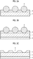
- the metal foil is dissolved together with the metal particles in a thickness direction at positions corresponding to the portions where the metal particles are embedded, and through-holes are formed as shown in Figs. 1A and 1B to be described later, whereby it is possible to easily produce a metal foil having a plurality of fine through-holes.
- a resin layer forming step using a composition containing a plurality of metal particles and a polymer component a resin layer 3 in which a plurality of metal particles 2 are partially embedded is formed on one principal surface of a metal foil 1 as shown in Fig. 1A .
- a protective layer 4 is preferably formed on a principal surface of the metal foil 1 opposite to the surface on which the resin layer 3 is formed as shown in Fig. 1B by an optional protective layer forming step using a composition containing a polymer component.
- through-holes 6 are formed in the resin layer 3 and the metal foil 1 as shown in Fig. 1C by a through-hole forming step of dissolving the metal particles and a part of the metal foil by bringing the metal foil having the resin layer into contact with an etchant.
- a perforated metal foil 10 having a plurality of through-holes 7 is formed as shown in Fig. 1D by a resin layer removing step of removing the resin layer.
- the resin layer and the protective layer are removed by the resin layer removing step as shown in Fig. ID, and thus the perforated metal foil 10 having a plurality of through-holes 7 is formed.
- a manufacturing method has a resin layer forming step of forming, using a composition containing a plurality of particles and a polymer component, a resin layer in which particles are at least partially embedded on one principal surface of a metal foil.
- the manufacturing method according to the second embodiment of the invention further has a particle removing step of removing the particles from the resin layer after the resin layer forming step.
- the manufacturing method according to the second embodiment of the invention further has a through-hole forming step of forming through-holes in the metal foil by bringing the metal foil having the resin layer into contact with an etchant after the particle removing step.
- the manufacturing method according to the second embodiment of the invention further has a resin layer removing step of removing the resin layer to produce a perforated metal foil having through-holes after the through-hole forming step.
- the manufacturing method according to the second embodiment of the invention preferably further has a protective layer forming step of forming, using a composition containing a polymer component, a protective layer on a principal surface of the metal foil opposite to the surface on which the resin layer is formed before the through-hole forming step.
- the through-holes are formed after the resin layer forming step and the particle removing step, and the resin layer is removed. Accordingly, it is possible to easily produce a metal foil having a plurality of fine through-holes.
- the inventors have thought that the reason why through-holes are formed starting from the recesses of the resin layer is that in the deepest portion of the recess, a very thin resin layer remains or there is a portion where the metal foil is exposed, and thus the etchant more preferentially enters from the recesses than other portions, and the through-holes are formed in the metal foil.
- a resin layer forming step using a composition containing a plurality of particles and a polymer component a resin layer 3 in which a plurality of particles 2 are at least partially embedded is formed on one principal surface of a metal foil 1 as shown in Fig. 2A .
- a protective layer 4 is preferably formed on a principal surface of the metal foil 1 opposite to the surface on which the resin layer 3 is formed as shown in Fig. 2B by an optional protective layer forming step using a composition containing a polymer component.
- the particles 2 are removed from the resin layer 3 as shown in Fig. 2C by a particle removing step of removing the particles from the resin layer, and thus a resin layer 3 in which recesses 5 corresponding to the portions where the particles 2 were embedded are formed is formed.
- through-holes 6 are formed in the resin layer 3 and the metal foil 1 as shown in Fig. 2D by a through-hole forming step of bringing the metal foil having the resin layer into contact with an etchant.
- a perforated metal foil 10 having a plurality of through-holes 7 is formed by a resin layer removing step of removing the resin layer.
- the resin layer and the protective layer are removed by the resin layer removing step as shown in Fig. 2E , and thus the perforated metal foil 10 having a plurality of through-holes 7 is formed.
- a resin layer in which the metal particles are partially embedded is formed on one principal surface of a metal foil.
- a resin layer in which at least the particles are partially embedded is formed on one principal surface of a metal foil.
- the resin layer forming step of the manufacturing method according to the second embodiment of the invention is the same as the resin layer forming step in the first embodiment, except that the particles contained in the composition may be particles other than metal particles. Therefore, the description will be collectively given as follows, except for the differences between the resin layer forming step of the first embodiment and the resin layer forming step of the second embodiment.
- the metal foil which is used in the resin layer forming step is not particularly limited as long as it is a metal foil containing a metal atom which dissolves in an etchant which is used in the through-hole forming step to be described later. It is preferably a foil made of a metal and/or a metal compound, and more preferably a foil made of a metal.
- the metal foil include aluminum foil, copper foil, silver foil, gold foil, platinum foil, stainless steel foil, titanium foil, tantalum foil, molybdenum foil, niobium foil, zirconium foil, tungsten foil, beryllium copper foil, phosphor bronze foil, brass foil, nickel silver foil, tin foil, lead foil, zinc foil, solder foil, iron foil, nickel foil, Permalloy foil, nichrome foil, 42 alloy foil, Kovar foil, Monel foil, Inconel foil, and Hastelloy foil.
- the metal foil may be a laminate of two or more different metals including the above types of metals.
- the metal foil lamination method is not particularly limited, and plating or a clad material is preferably used.
- the metal which is used for plating is not particularly limited as long as it is a metal containing a metal atom which dissolves in an etchant, and it is preferably a metal.
- the plating species include nickel, chromium, cobalt, iron, zinc, tin, copper, silver, gold, platinum, palladium, and aluminum.
- the plating method is not particularly limited, and any of electroless plating, electrolytic plating, hot dip plating, a chemical conversion treatment, and the like is used.
- the metal which is used to form a clad material for the metal foil is not particularly limited as long as it is a metal containing a metal atom which dissolves in an etchant, and it is preferably a metal.
- the metal species include the metals which are used for the metal foil.
- the thickness of the metal foil is preferably 10 ⁇ m to 100 ⁇ m, and more preferably 10 ⁇ m to 40 ⁇ m.
- the average thickness of the metal foil refers to the average of the thicknesses measured at any five points using a contact film thickness meter (digital electronic micrometer).
- composition which is used in the resin layer forming step contains at least a plurality of metal particles and a polymer component.
- the metal particles contained in the composition are not particularly limited as long as these are particles containing a metal atom which dissolves in an etchant which is used in the through-hole forming step to be described later.
- the metal particles are preferably particles made of a metal and/or a metal compound, and more preferably particles made of a metal.
- metal constituting the metal particles include aluminum, nickel, iron, copper, stainless steel, titanium, tantalum, molybdenum, niobium, zirconium, tungsten, beryllium, and alloys thereof. These may be used alone or in combination of two or more thereof.
- aluminum, nickel, and copper are preferable, and aluminum and copper are more preferable.
- Examples of the metal compound constituting the metal particles include oxides, complex oxides, hydroxides, carbonates, sulfates, silicates, phosphates, nitrides, carbides, sulfides, and composite materials of at least two or more types thereof. Specific examples thereof include copper oxide, aluminum oxide, aluminum nitride, and aluminum borate.
- the metal particles and the above-described metal foil contain the same metal atom from the viewpoint of recovering the etchant which is used in the through-hole removing step to be described later and recycling the dissolved metal.
- the shape of the metal particles is not particularly limited.
- the shape is preferably a spherical shape, and more preferably closer to a true spherical shape.
- the average particle diameter of the metal particles is preferably 1 to 10 ⁇ m, and more preferably greater than 2 ⁇ m and not greater than 6 ⁇ m from the viewpoint of dispersibility in the composition.
- the average particle diameter of the metal particles refers to the cumulative 50% diameter of the particle size distribution measured by a laser diffraction/scattering type particle diameter measuring device (MICROTRAC MT3000 manufactured by Nikkiso Co., Ltd.).
- the content of the metal particles is preferably 0.05 to 95 mass%, more preferably 1 to 50 mass%, and even more preferably 3 to 25 mass% with respect to the total solid content contained in the composition.
- the particles contained in the composition are not particularly limited.
- the material of the particles is preferably an inorganic filler or an inorganic-organic composite filler.
- Examples of the inorganic filler include metals and metal compounds, and examples of the metal compounds include oxides, complex oxides, hydroxides, carbonates, sulfates, silicates, phosphates, nitrides, carbides, sulfides, and composite materials of at least two or more types thereof.
- Specific examples thereof include glass, zinc oxide, silica, alumina, zirconium oxide, tin oxide, potassium titanate, strontium titanate, aluminum borate, magnesium oxide, magnesium borate, aluminum hydroxide, magnesium hydroxide, calcium hydroxide, titanium hydroxide, basic magnesium sulfate, calcium carbonate, magnesium carbonate, calcium sulfate, magnesium sulfate, calcium silicate, magnesium silicate, calcium phosphate, silicon nitride, titanium nitride, aluminum nitride, silicon carbide, titanium carbide, zinc sulfide, and composite materials of at least two or more types thereof.
- glass silica, alumina, potassium titanate, strontium titanate, aluminum borate, magnesium oxide, calcium carbonate, magnesium carbonate, calcium silicate, magnesium silicate, calcium phosphate, and calcium sulfate are preferable.
- Examples of the inorganic-organic composite filler include a composite material obtained by coating the surfaces of particles such as synthetic resin particles or natural polymer particles with the above-described inorganic filler.
- synthetic resin particles include particles of resins such as acrylic resins, polyethylene, polypropylene, polyethylene oxide, polypropylene oxide, polyethylene imine, polystyrene, polyurethane, polyurea, polyester, polyamide, polyimide, carboxymethyl cellulose, gelatin, starch, chitin, and chitosan.
- resins such as acrylic resins, polyethylene, polypropylene, polyethylene oxide, polypropylene oxide, polyethylene imine, polystyrene, polyurethane, polyurea, polyester, polyamide, polyimide, carboxymethyl cellulose, gelatin, starch, chitin, and chitosan.
- particles of resins such as acrylic resins, polyethylene, polypropylene, and polystyrene are preferable.
- the shape of the particles is not particularly limited.
- the shape is preferably a spherical shape, and more preferably closer to a true spherical shape.
- the average particle diameter of the particles is preferably 1 to 10 ⁇ m, and more preferably greater than 2 ⁇ m and not greater than 6 ⁇ m from the viewpoint of dispersibility in the composition and removal in the particle removing step to be described later.
- the average particle diameter of the particles refers to the cumulative 50% diameter of the particle size distribution measured by a laser diffraction/scattering type particle diameter measuring device (MICROTRAC MT3000 manufactured by Nikkiso Co., Ltd.).
- the content of the particles is preferably 0.05 to 95 mass%, more preferably 1 to 50 mass%, and even more preferably 3 to 25 mass% with respect to the total solid content contained in the composition.
- the polymer component contained in the composition is not particularly limited, and a conventionally known polymer component can be used.
- the polymer component include epoxy-based resins, silicone-based resins, acrylic resins, urethane-based resins, ester-based resins, urethane acrylate-based resins, silicone acrylate-based resins, epoxy acrylate-based resins, ester acrylate-based resins, polyamide-based resins, polyimide-based resins, polycarbonate-based resins, and phenolic resins. These may be used alone or in combination of two or more types thereof.
- the polymer component is preferably a resin material selected from the group consisting of phenolic resins, acrylic resins, and polyimide-based resins since the above resins have excellent acid resistance, and thus desired through-holes are easily obtained even in a case where an acidic solution is used as an etchant which is used in the through-hole forming step to be described later.
- the polymer component contained in the composition is preferably a water insoluble and alkaline water soluble polymer (hereinafter, also abbreviated as "alkaline water soluble polymer”), that is, a homopolymer containing an acidic group in a main chain or a side chain of the polymer, a copolymer thereof, or a mixture thereof.
- alkaline water soluble polymer a water insoluble and alkaline water soluble polymer
- alkaline water soluble polymer those having an acidic group in a main chain and/or a side chain of the polymer are preferable from the viewpoint of further facilitating removal in the resin layer removing step to be described later.
- the acidic group examples include a phenolic group (-Ar-OH), a sulfonamide group (-SO 2 NH-R), a substituted sulfonamide-based acid group (hereinafter, referred to as "active imide group”) [-SO 2 NHCOR, -SO 2 NHSO 2 R, -CONHSO 2 R], a carboxyl group (-CO 2 H), a sulfo group (-SO 3 H), and a phosphonic group (-OPO 3 H 2 ).
- Ar represents a divalent aryl linking group which may have a substituent
- R represents a hydrocarbon group which may have a substituent
- alkaline water soluble polymers having an acidic group alkaline water soluble polymers having a phenolic group, a carboxyl group, a sulfonamide group, or an active imide group are preferable. Particularly, alkaline water soluble polymers having a phenolic group or a carboxyl group are most preferable from the viewpoint of the balance between the hardness of the resin layer to be formed and the removability in the resin layer removing step to be described later.
- alkaline water soluble polymer having an acidic group examples include as follows.
- alkaline water soluble polymer having a phenolic group examples include novolak resins manufactured from one or more types of phenols such as phenol, o-cresol, m-cresol, p-cresol, and xylenol and aldehydes such as formaldehyde and paraformaldehyde, and polycondensates of pyrogallol and acetone. Copolymers obtained by copolymerization of a compound having a phenolic group can also be included. Examples of the compound having a phenolic group include acrylamide, methacrylamide, acrylic acid ester, methacrylic acid ester, and hydroxystyrene having a phenolic group.
- novolak resins or copolymers of hydroxystyrene are preferable.
- examples of commercially available products of the copolymers of hydroxystyrene include MARUKALINKER M H-2, MARUKALINKER M S-4, MARUKALINKER M S-2, MARKA LINKER M S-1, all manufactured by MARUZEN PETROCHEMICAL CO., LTD., and VP-8000 and VP-15000, all manufactured by NIPPON SODA CO., LTD.
- alkaline water soluble polymer having a sulfonamide group examples include polymers including, as a main constitutional component, a minimum constitutional unit derived from a compound having a sulfonamide group.
- the compound examples include compounds having at least one sulfonamide group in which at least one hydrogen atom is bonded to a nitrogen atom and at least one polymerizable unsaturated group in the molecule.
- low-molecular-weight compounds having an acryloyl group, allyl group, or vinyloxy group and a substituted or mono-substituted aminosulfonyl group or substituted sulfonylimino group in the molecule are preferable.
- m-aminosulfonyl phenyl methacrylate, N-(p-aminosulfonylphenyl)methacrylamide, N-(p-aminosulfonylphenyl)acrylamide, or the like can be preferably used.
- alkaline water soluble polymer having an active imide group examples include polymers including, as a main constitutional component, a minimum constitutional unit derived from a compound having an active imide group.
- the compound examples include compounds having at least one active imide group represented by the following structural formula and at least one polymerizable unsaturated group in the molecule.
- N-(p-toluenesulfonyl)methacrylamide, N-(p-toluenesulfonyl)acrylamide, or the like can be preferably used.
- alkaline water soluble polymer having a carboxyl group examples include polymers including, as a main constitutional component, a minimum constitutional unit derived from a compound having at least one carboxyl group and at least one polymerizable unsaturated group in the molecule. Specific examples thereof include polymers using an unsaturated carboxylic acid compound such as acrylic acid, methacrylic acid, maleic acid anhydride, or itaconic acid.
- alkali soluble polymer having a sulfo group examples include polymers including, as a main constitutional component, a minimum constitutional unit derived from a compound having at least one sulfo group and at least one polymerizable unsaturated group in the molecule.
- alkaline water soluble polymer having a phosphonic group examples include polymers including, as a main constitutional component, a minimum constitutional unit derived from a compound having at least one phosphonic group and at least one polymerizable unsaturated group in the molecule.
- the alkaline water soluble polymer it is not necessary for the alkaline water soluble polymer to have only one type of minimum constitutional unit having an acidic group. Two or more types of minimum constitutional units having the same acidic group, or those obtained by copolymerizing two or more types of minimum constitutional units having different acidic groups can be used.
- a copolymerization method As a copolymerization method, a graft copolymerization method, a block copolymerization method, or a random copolymerization method, which have been known, can be used.
- a compound having an acidic group to be copolymerized is preferably contained in an amount of 10 mol% or greater, and more preferably 20 mol% or greater.
- the polymer component preferably has a weight-average molecular weight of 1.0 ⁇ 10 3 to 2.0 ⁇ 10 5 and a number-average molecular weight of 5.0 ⁇ 10 2 to 1.0 ⁇ 10 5 , regardless of the fact that the polymer component is either a homopolymer or a copolymer.
- the polymer component preferably has a polydispersity (weight-average molecular weight/number-average molecular weight) of 1.1 to 10.
- the mixing ratio by weight of a minimum constitutional unit constituting a main chain and/or a side chain of the copolymer and derived from a compound having an acidic group to another minimum constitutional unit constituting a part of the main chain and/or a side chain and containing no acidic group is preferably within a range of 50:50 to 5:95, and more preferably 40:60 to 10:90.
- the polymer component is preferably used within a range of 30 to 99 mass%, more preferably 40 to 95 mass%, and particularly preferably 50 to 90 mass% with respect to the total solid content contained in the composition.
- the specific gravity of the metal particles is preferably greater than the specific gravity of the polymer component since forming through-holes becomes easier in the through-hole forming step to be described later. Specifically, it is more preferable that the specific gravity of the metal particles is 1.5 or greater, and the specific gravity of the polymer component is 0.9 or greater and less than 1.5.
- the specific gravity of the particles is preferably greater than the specific gravity of the polymer component since forming through-holes becomes easier in the through-hole forming step to be described later, in other words, the surface of the metal foil is likely to be exposed to the deepest portion of the recess as the starting point of the through-hole in the resin layer.
- the specific gravity of the particles is 1.5 or greater
- the specific gravity of the polymer component is 0.9 or greater and less than 1.5.
- a nonionic surfactant described in JP1987-251740A JP-S62-251740A
- JP1991-208514A JP-H3-208514A
- an amphoteric surfactant described in JP1984-121044A JP-S59-121044A
- JP1992-013149A JP-H4-013149A
- nonionic surfactant examples include sorbitan tristearate, sorbitan monopalmitate, sorbitan trioleate, stearic acid monoglyceride, and polyoxyethylene nonyl phenyl ether.
- amphoteric surfactant examples include alkyl di(aminoethyl)glycine, alkylpolyaminoethylglycine hydrochloride, 2-alkyl-N-carboxyethyl-N-hydroxyethyl imidazolinium betaine, and an N-tetradecyl-N,N-betaine type (for example, trade name: AMORGEN K, manufactured by DAIICHI KOGYO Co., Ltd.).
- the content thereof is preferably 0.01 to 10 mass%, and more preferably 0.05 to 5 mass% with respect to the total solid content contained in the composition.
- a solvent can be added to the composition from the viewpoint of workability in forming the resin layer.
- the solvent include ethylene dichloride, cyclohexanone, methyl ethyl ketone, methanol, ethanol, propanol, ethylene glycol monomethyl ether, 1-methoxy-2-propanol, 2-methoxyethyl acetate, 1-methoxy-2-propyl acetate, dimethoxyethane, methyl lactate, ethyl lactate, N,N-dimethylacetamide, N,N-dimethylformamide, tetramethylurea, N-methylpyrrolidone, dimethylsulfoxide, sulfolane, ⁇ -butyrolactone, toluene, and water. These may be used alone or in combination of two or more thereof.
- the method of forming a resin layer using the above-described composition is not particularly limited, and a method of forming a resin layer by applying the composition to a metal foil is preferable.
- the method for application to a metal foil is not particularly limited, and for example, a bar coating method, a slit coating method, an ink jet method, a spray method, a roll coating method, a spin coating method, a cast coating method, a slit and spin method, a transfer method, or the like can be used.
- the resin layer is preferably formed so as to satisfy Formula (1) since forming through-holes becomes easier in the through-hole forming step to be described later.
- n 1 ⁇ r 1
- n 1 represents the thickness of the resin layer to be formed
- r 1 represents the average particle diameter of the metal particles which are contained in the composition
- each of the units of n 1 and r 1 is ⁇ m.
- the resin layer is preferably formed so as to satisfy Formula (2) since forming through-holes becomes easier in the through-hole forming step to be described later.
- n 2 represents the thickness of the resin layer to be formed
- r 2 represents the average particle diameter of the particles which are contained in the composition
- each of the units of n 2 and r 2 is ⁇ m.
- the thickness of the resin layer to be formed through the resin layer forming step is preferably 0.5 to 4 ⁇ m, and more preferably 1 ⁇ m or greater and 2 ⁇ m or less.
- the average thickness of the resin layer refers to the average of the thicknesses measured at any five points in a case where the resin layer is cut using a microtome and a cross section thereof is observed by an electron microscope.
- a protective layer forming step of forming a protective layer, using a composition containing a polymer component, on a principal surface of the metal foil opposite to the surface on which the resin layer is formed is preferably provided before the through-hole forming step from the viewpoint of workability in the through-hole forming step to be described later.
- examples of the polymer component are the same as the examples of the polymer component contained in the composition which is used in the above-described resin layer forming step. That is, the protective layer which is formed in an optional protective layer forming step is the same as the above-described resin layer, except that the above-described metal particles or particles are not embedded. In addition, regarding a method of forming the protective layer, the protective layer can be formed in the same manner as in the case of the above-described resin layer, except that the above-described metal particles or particles are not used.
- the order is not particularly limited as long as the protective layer forming step is provided before the through-hole forming step, and the protective layer forming step may be performed before or after or simultaneously with the above-described resin layer forming step.
- the particles are removed from the resin layer after the above-described resin layer forming step.
- the method of removing the particles is not particularly limited.
- the particles can be removed by applying an external force to portions of the particles not embedded in the resin layer using a sponge, a brush, or the like.
- the method of removing the particles is preferably a method of removing the particles by rubbing the surface of the resin layer in which the particles are at least partially embedded while the surface of the resin layer is immersed in a solvent.
- the surface of the resin layer in which the particles are at least partially embedded refers to the particles and the surface of the resin layer in a case where the particles are partially embedded in the resin layer as shown in Fig. 2A .
- the surface of the resin layer in which the particles are at least partially embedded refers to the surface of the resin layer.
- the solvent is not particularly limited as long as it is a solvent capable of dissolving the resin layer.
- a solvent similar to the solvent described as an optional component of the composition which is used in the above-described resin layer forming step can be used.
- the method of rubbing the surface of the resin layer is not particularly limited, and examples thereof include a rubbing method using a sponge, a brush (for example, a wire brush or a nylon brush roll), or the like.
- the metal foil having the resin layer is brought into contact with an etchant to dissolve the metal particles and a part of the metal foil, and through-holes are formed in the metal foil.
- This step is a step of forming through-holes in the metal foil by a so-called chemical etching treatment.
- the metal foil having the resin layer is brought into contact with an etchant to form through-holes in the metal foil.
- This step is a step of forming through-holes in the metal foil by a so-called chemical etching treatment.
- the through-hole forming step in the first embodiment is the same as the through-hole forming step in the second embodiment, except that the metal particles are also dissolved together with the metal foil. Therefore, the description will be collectively given as follows, except for the differences between the through-hole forming step of the first embodiment and the through-hole forming step of the second embodiment.
- an acidic or alkaline chemical solution or the like can be appropriately used as long as it is an etchant suitable for the metal species of the metal foil and the metal particles.
- Examples of the acid include hydrochloric acid, sulfuric acid, nitric acid, hydrofluoric acid, hydrogen peroxide, and acetic acid.
- alkali examples include caustic soda and caustic potash.
- alkali metal salt examples include alkali metal silicates such as sodium metasilicate, sodium silicate, potassium metasilicate, and potassium silicate; alkali metal carbonates such as sodium carbonate and potassium carbonate; alkali metal aluminates such as sodium aluminate and potassium aluminate; alkali metal aldonates such as sodium gluconate and potassium gluconate; and alkali metal hydrogenphosphates such as sodium secondary phosphate, potassium secondary phosphate, sodium tertiary phosphate, and potassium tertiary phosphate.
- alkali metal silicates such as sodium metasilicate, sodium silicate, potassium metasilicate, and potassium silicate
- alkali metal carbonates such as sodium carbonate and potassium carbonate
- alkali metal aluminates such as sodium aluminate and potassium aluminate
- alkali metal aldonates such as sodium gluconate and potassium gluconate
- alkali metal hydrogenphosphates such as sodium secondary phosphate
- Inorganic salts such as iron chloride (III) and copper chloride (II) can also be used. These may be used alone or as a mixture of two or more types thereof.
- the treatment for forming the through-holes is performed by bringing the metal foil having the resin layer containing the metal particles or the metal foil having the resin layer after the particle removing step into contact with the above-described etchant.
- the contacting method is not particularly limited, and examples thereof include an immersion method and a spray method. Among these, an immersion method is preferable.
- the immersion treatment time is preferably 15 seconds to 10 minutes, and more preferably 1 minute to 6 minutes.
- the liquid temperature of the etchant during immersion is preferably 25°C to 70°C, and more preferably 30°C to 60°C.
- the resin layer removing step of the manufacturing method according to the embodiment of the invention the resin layer is removed after the above-described through-hole forming step to produce a perforated metal foil having through-holes.
- the method of removing the resin layer is not particularly limited, and in a case where the above-described alkaline water soluble polymer is used as the polymer component, a method of dissolving and removing the resin layer using an alkaline aqueous solution is preferable.
- alkaline aqueous solution examples include inorganic alkalis such as sodium hydroxide, potassium hydroxide, sodium carbonate, sodium silicate, sodium metasilicate, and aqueous ammonia; primary amines such as ethylamine and n-propylamine; secondary amines such as diethylamine and di-n-butylamine; tertiary amines such as triethylamine and methyldiethylamine; alcohol amines such as dimethylethanolamine and triethanolamine; quaternary ammonium salts such as tetramethylammonium hydroxide and tetraethylammonium hydroxide; and cyclic amines such as pyrrole and piperidine. These may be used alone or in combination of two or more types thereof.
- inorganic alkalis such as sodium hydroxide, potassium hydroxide, sodium carbonate, sodium silicate, sodium metasilicate, and aqueous ammonia
- primary amines such as
- An appropriate amount of alcohols or a surfactant can be added to the alkaline aqueous solution and used.
- the treatment for removing the resin layer is performed by, for example, bringing the metal foil having the resin layer after the through-hole forming step into contact with the above-described alkaline aqueous solution.
- the contacting method is not particularly limited, and examples thereof include an immersion method and a spray method. Among these, an immersion method is preferable.
- the immersion treatment time is preferably 5 seconds to 5 minutes, and more preferably 10 seconds to 2 minutes.
- the temperature of the alkaline aqueous solution during immersion is preferably 25°C to 60°C, and more preferably 30°C to 50°C.
- the average opening diameter of the through-holes of the perforated metal foil, which are formed by the through-hole forming step and the resin layer removing step described above is preferably 0.1 to 300 ⁇ m, and more preferably 1 to 100 ⁇ m.
- the surface of the perforated metal foil is imaged from directly above using a high resolution scanning electron microscope (scanning electron microscope (SEM)) at a magnification of 100 to 10,000 times.
- SEM scanning electron microscope
- the obtained SEM photograph at least 20 through-holes having an annular periphery are extracted, and their diameters are read to obtain the opening diameters.
- the average of the opening diameters is calculated as the average opening diameter.
- a magnification within the above-described range can be appropriately selected so as to obtain a SEM photograph in which at least 20 through-holes can be extracted.
- the maximum distance between the end portions of the through-hole is measured as the opening diameter. That is, since the shape of the opening of the through-hole is not limited to a substantially circular shape, the maximum distance between the end portions of the through-hole is defined as the opening diameter in a case where the shape of the opening is non-circular. Therefore, for example, even in a case of a through-hole having such a shape that two or more through-holes are integrated, the through-hole is regarded as one through-hole, and the maximum distance between the end portions of the through-hole is defined as the opening diameter.
- the average opening diameter of the through-holes of the perforated metal foil can be adjusted by, for example, an immersion time in the etchant in the above-described through-hole forming step.
- the average opening ratio by the through-holes in the perforated metal foil, which are formed by the through-hole forming step and the resin layer removing step described above is preferably 1% to 50%, and more preferably 5% to 30%.
- a parallel light optical unit is installed on one surface side of the perforated metal foil, parallel light is transmitted, and the surface of the perforated metal foil is imaged using an optical microscope at a magnification of 100 times from the other surface of the perforated metal foil to acquire a photograph.
- a proportion opening area/geometric area
- the average of the proportions in the visual fields is calculated as the average opening ratio.
- the average opening ratio by the through-holes in the perforated metal foil can be adjusted by, for example, the content of the metal particles or the particles in the composition which is used in the above-described resin layer forming step.
- the manufacturing method according to the embodiment of the invention preferably has an anticorrosion treatment step.
- the timing of the anticorrosion treatment is not particularly limited.
- the anticorrosion treatment may be a treatment to be performed on the metal foil which is used in the resin layer forming step, a treatment for adding triazoles or the like to be described later to the alkaline aqueous solution in the resin layer removing step, or a treatment to be performed after the resin layer removing step.
- Examples of the anticorrosion treatment include a treatment for immersing the metal foil in a solution having a pH of 5 to 8.5 in which at least triazoles are dissolved in a solvent to form an organic dielectric film.
- triazoles include benzotriazole (BTA) and tolyltriazole (TTA).
- Water or organic solvents can be appropriately used as a solvent to be used in the anticorrosion treatment, and the solvent is preferably water mainly composed of deionized water in consideration of the uniformity of an organic dielectric film to be formed, easiness of thickness control at mass production, simplicity, influence on the environment, and the like.
- the concentration of the triazoles to be dissolved can be appropriately determined based on the relationship with the thickness of an organic dielectric film to be formed or the treatment time, and may be about 0.005 to 1 wt% in general.
- the temperature of the solution may be room temperature.
- the solution may be warmed and used as necessary.
- the immersion time of the metal foil in the solution can be appropriately determined based on the relationship with the concentration of the triazoles to be dissolved or the thickness of an organic dielectric film to be formed, and may be about 0.5 to 30 seconds in general.
- anticorrosion treatment examples include a method of forming an inorganic dielectric film mainly composed of a hydrated oxide of chromium by immersing the metal foil in an aqueous solution prepared by dissolving at least one selected from the group of chromium trioxide, chromate, and bichromate in water.
- potassium chromate or sodium chromate is preferable as the chromate
- potassium bichromate or sodium bichromate is preferable as the bichromate.
- the concentration thereof is set to 0.1 to 10 mass%, and the liquid temperature may be about room temperature to 60°C.
- the pH value of the aqueous solution is not particularly limited from the acidic region to the alkaline region, and is set to 1 to 12 in general.
- the immersion time of the metal foil is appropriately selected depending on the thickness of an inorganic dielectric film to be formed and the like.
- water washing is preferably performed after completion of each of the treatment steps described above.
- pure water, well water, tap water, or the like can be used.
- a nipping device may be used.
- the treatments in the steps may be performed using a cut sheet-like metal foil on a so-called sheet-by-sheet basis, or performed in a so-called roll-to-roll (hereinafter, also referred to as "R to R") manner while a long metal foil is transported in a longitudinal direction according to a predetermined transportation path.
- R to R roll-to-roll
- R to R refers to a manufacturing method in which while a metal foil is fed from a roll formed by winding a long metal foil and is transported in a longitudinal direction, treatments such as the resin layer forming step and the through-hole forming step described above are continuously performed in order by treatment devices disposed on the transportation path, and the treated metal foil (that is, perforated metal foil) is wound into a roll shape again.
- Productivity can be improved by performing the manufacturing method according to the embodiment of the invention in a R to R manner.
- the perforated metal foil produced by the manufacturing method according to the embodiment of the invention can be used as a collector for an electric storage device (hereinafter, also referred to as "collector").
- the perforated metal foil has a plurality of through-holes in a thickness direction. Accordingly, for example, in a case where the collector is used in a lithium ion capacitor, pre-doping of lithium within a short period of time becomes possible, and it becomes possible to more uniformly disperse lithium. In addition, adhesiveness to active material layers or activated carbon is improved, and it is possible to produce electric storage devices which are excellent in terms of productivity such as cycle characteristics, output characteristics, and coating suitability.
- the collector using the perforated metal foil produced by the manufacturing method according to the embodiment of the invention is further improved in terms of adhesiveness to active material layers, and thus it is possible to produce electric storage devices having improved cycle characteristics.
- the active material layer is not particularly limited, and a known active material layer which is used in a conventional electric storage device can be used.
- An electrode in which the perforated metal foil produced by the manufacturing method according to the embodiment of the invention is used as a collector can be used as a positive electrode or a negative electrode of an electric storage device.
- a positive electrode in which the perforated metal foil produced by the manufacturing method according to the embodiment of the invention is used as a collector has a positive electrode collector in which the perforated metal foil is used for the positive electrode and a layer containing a positive electrode active material which is formed on a surface of the positive electrode collector (positive electrode active material layer).
- a negative electrode in which the perforated metal foil produced by the manufacturing method according to the embodiment of the invention is used as a collector has a negative electrode collector in which the perforated metal foil is used for the negative electrode and a layer containing a negative electrode active material which is formed on a surface of the negative electrode collector.
- the perforated metal foil produced by the manufacturing method according to the embodiment of the invention can be used not only as a current collector for an electric storage device, but also as a heat resistant filter, a heat resistant fine particle filter, a sound insulating material, an oil recovery filter, an electrostatic filter, an antibacterial filter, a liquid modification filter, a water electrolysis filter, an exhaust gas purification filter, a food filtration filter, a marine biological filtration filter, a dust filter, a deoxyribonucleic acid (DNA) filter, a fine powder classification filter, a solid-liquid separation filter, a deodorization filter, a photocatalyst carrier, a hydrogen generating catalyst carrier, an enzymatic electrode, a carrier of a noble metal absorber, an antibacterial carrier, an adsorbent, an absorbent, an optical filter, a far infrared cut filter, a sound insulating/absorbing material, an electromagnetic wave shield, a gas diffusion layer/separator of a direct type fuel cell, a net for
- the manufacturing method according to the first embodiment of the invention was performed as an example.
- a copper foil (JIS C 1100-H, electrolytic copper foil) having an average thickness of 15 ⁇ m and a size of 200 mm ⁇ 200 mm was used as a metal foil.
- a resin layer forming composition 1 prepared to have the following composition was applied to one surface of a copper foil and dried to form a resin layer A1 having a thickness of about 1 ⁇ m.
- the copper foil having the resin layer A1 and the protective layer B1 was immersed for 5 minutes in an etchant [concentration of iron (III) chloride: 30 mass%, concentration of hydrochloric acid: 3.65 mass%] kept at 50°C, and then washed with water by spraying and dried to form through-holes.
- an etchant concentration of iron (III) chloride: 30 mass%, concentration of hydrochloric acid: 3.65 mass%
- the copper foil after the formation of the through-holes was immersed for 120 seconds in an alkaline aqueous solution (concentration of sodium hydroxide: 0.4 mass%) having a liquid temperature of 50°C to dissolve and remove the resin layer A1 and the protective layer B 1.
- the copper foil was washed with water by spraying and dried to produce a perforated metal foil having through-holes.
- a perforated metal foil having through-holes was produced in the same manner as in Example 1-1, except that the following (a-2) resin layer forming step was performed instead of (a-1) resin layer forming step.
- a resin layer forming composition 2 prepared to have the following composition was applied to one surface of a copper foil and dried to form a resin layer A2 having a thickness of about 0.5 ⁇ m.
- a perforated metal foil having through-holes was produced in the same manner as in Example 1-1, except that an aluminum foil (JIS H 4160, alloy number: 1085-H) having an average thickness of 20 ⁇ m was used instead of the copper foil, aluminum particles (#700, average particle diameter: 5 to 6 ⁇ m, manufactured by Minaruko Ltd.) were used instead of the copper particles, and the following (b-2) through-hole forming step was performed instead of (b-1) through-hole forming step.
- JIS H 4160 alloy number: 1085-H
- aluminum particles #700, average particle diameter: 5 to 6 ⁇ m, manufactured by Minaruko Ltd.
- the aluminum foil having the resin layer A1 and the protective layer B1 was immersed for 1 minute in an etchant [concentration of copper (II) chloride: 0.65 mass%, concentration of hydrochloric acid: 9 mass%] cooled to 10°C, and then washed with water by spraying and dried to form through-holes.
- an etchant concentration of copper (II) chloride: 0.65 mass%, concentration of hydrochloric acid: 9 mass%
- a perforated metal foil having through-holes was produced in the same manner as in Example 1-1, except that a stainless steel foil (SUS304) having an average thickness of 15 ⁇ m was used instead of the copper foil.
- SUS304 stainless steel foil
- a perforated metal foil having through-holes was produced in the same manner as in Example 1-1, except that a nickel foil having an average thickness of 15 ⁇ m was used instead of the copper foil, and the following (b-3) through-hole forming step was performed instead of (b-1) through-hole forming step.
- the nickel foil having the resin layer A1 and the protective layer B1 was immersed for 3 minutes in a nickel etching liquid-H (manufactured by NIHON-SANGYO Co., Ltd.) kept at 40°C, and then washed with water by spraying and dried to form through-holes.
- a nickel etching liquid-H manufactured by NIHON-SANGYO Co., Ltd.
- a perforated metal foil having through-holes was produced in the same manner as in Example 1, except that the following (a-3) resin layer forming step was performed instead of (a-1) resin layer forming step.
- a resin layer forming composition 3 prepared to have the following composition was applied to one surface of a copper foil and dried to form a resin layer A3 having a thickness of about 1 ⁇ m.
- Resin Layer Forming Composition 3 • Copolymer of methacrylic acid, ethyl methacrylate, and butyl methacrylate (26mol %/37 mol%/37 mol%, weight-average molecular weight: 50,000) 1.2 g • HXR-Cu (copper particles, average particle diameter: 5.0 ⁇ m, manufactured by Nippon Atomized Metal Powders Corporation) 0.3 g • MEGAFACE F-780-F (surfactant, manufactured by DIC Corporation) 0.1 g • Methyl ethyl ketone 1.0 g • 1-Methoxy-2-propanol 5.0 g
- a perforated metal foil having through-holes was produced in the same manner as in Example 1-1, except that the following (a-4) resin layer forming step was performed instead of (a-1) resin layer forming step.
- a resin layer forming composition 4 prepared to have the following composition was applied to one surface of a copper foil and dried to form a resin layer A4 having a thickness of about 0.5 ⁇ m.
- Resin Layer Forming Composition 4 • Copolymer of methacrylic acid, ethyl methacrylate, and butyl methacrylate (26 mol%/37 mol%/37 mol%, weight-average molecular weight: 50,000) 0.6 g • ATP-Cu (copper particles, average particle diameter: 1.5 ⁇ m, manufactured by Nippon Atomized Metal Powders Corporation) 0.1 g • MEGAFACE F-780-F (surfactant, manufactured by DIC Corporation) 0.1 g • Methyl ethyl ketone 1.0 g • 1-Methoxy-2-propanol 5.0 g
- a perforated metal foil having through-holes was produced in the same manner as in Example 1-6, except that an aluminum foil (JIS H 4160, alloy number: 1085-H) having an average thickness of 20 ⁇ m was used instead of the copper foil, aluminum particles (#700, average particle diameter: 5 to 6 ⁇ m, manufactured by Minaruko Ltd.) were used instead of the copper particles, and the following (b-4) through-hole forming step was performed instead of (b-1) through-hole forming step.
- JIS H 4160 alloy number: 1085-H
- aluminum particles #700, average particle diameter: 5 to 6 ⁇ m, manufactured by Minaruko Ltd.
- the aluminum foil having the resin layer A3 and the protective layer B3 was immersed for 1 minute in an etchant [concentration of copper (II) chloride: 0.65 mass%, concentration of hydrochloric acid: 9 mass%] cooled to 10°C, and then washed with water by spraying and dried to form through-holes.
- an etchant concentration of copper (II) chloride: 0.65 mass%, concentration of hydrochloric acid: 9 mass%
- a perforated metal foil having through-holes was produced in the same manner as in Example 1-6, except that a stainless steel foil (SUS304) having an average thickness of 15 ⁇ m was used instead of the copper foil.
- SUS304 stainless steel foil
- a perforated metal foil having through-holes was produced in the same manner as in Example 1-6, except that a nickel foil having an average thickness of 15 ⁇ m was used instead of the copper foil, and the following (b-5) through-hole forming step was performed instead of (b-1) through-hole forming step.
- the nickel foil having the resin layer A3 and the protective layer B3 was immersed for 3 minutes in a nickel etching liquid-H (manufactured by NIHON-SANGYO Co., Ltd.) kept at 40°C, and then washed with water by spraying and dried to form through-holes.
- a nickel etching liquid-H manufactured by NIHON-SANGYO Co., Ltd.
- a perforated metal foil having through-holes was produced in the same manner as in Example 1-1, except that the following (a-5) resin layer forming step was performed instead of (a-1) resin layer forming step.
- a resin layer forming composition 5 prepared to have the following composition was applied to one surface of a copper foil and dried to form a resin layer A5 having a thickness of about 1 ⁇ m.
- Resin Layer Forming Composition 5 • Copolymer of p-hydroxystyrene (weight-average molecular weight: 30,000) 1.2 g • HXR-Cu (copper particles, average particle diameter: 5.0 ⁇ m, manufactured by Nippon Atomized Metal Powders Corporation) 0.3 g • MEGAFACE F-780-F (surfactant, manufactured by DIC Corporation) 0.1 g • Methyl ethyl ketone 1.0 g • 1-Methoxy-2-propanol 5.0 g
- a perforated metal foil having through-holes was produced in the same manner as in Example 1-1, except that the following (a-6) resin layer forming step was performed instead of (a-1) resin layer forming step.
- a resin layer forming composition 6 prepared to have the following composition was applied to one surface of a copper foil and dried to form a resin layer A6 having a thickness of about 0.5 ⁇ m.
- Resin Layer Forming Composition 6 • Copolymer of p-hydroxystyrene (weight-average molecular weight: 30,000) 1.2 g • ATP-Cu (copper particles, average particle diameter: 1.5 ⁇ m, manufactured by Nippon Atomized Metal Powders Corporation) 0.1 g • MEGAFACE F-780-F (surfactant, manufactured by DIC Corporation) 0.1 g • Methyl ethyl ketone 1.0 g • 1-Methoxy-2-propanol 5.0 g
- a perforated metal foil having through-holes was produced in the same manner as in Example 1-11, except that an aluminum foil (JIS H 4160, alloy number: 1085-H) having an average thickness of 20 ⁇ m was used instead of the copper foil, aluminum particles (#700, average particle diameter: 5 to 6 ⁇ m, manufactured by Minaruko Ltd.) were used instead of the copper particles, and the following (b-6) through-hole forming step was performed instead of (b-1) through-hole forming step.
- JIS H 4160 alloy number: 1085-H
- aluminum particles #700, average particle diameter: 5 to 6 ⁇ m, manufactured by Minaruko Ltd.
- the aluminum foil having the resin layer A5 and the protective layer B5 was immersed for 1 minute in an etchant [concentration of copper (II) chloride: 0.65 mass%, concentration of hydrochloric acid: 9 mass%] cooled to 10°C, and then washed with water by spraying and dried to form through-holes.
- an etchant concentration of copper (II) chloride: 0.65 mass%, concentration of hydrochloric acid: 9 mass%
- a perforated metal foil having through-holes was produced in the same manner as in Example 1-11, except that a stainless steel foil (SUS304) having an average thickness of 15 ⁇ m was used instead of the copper foil.
- SUS304 stainless steel foil
- a perforated metal foil having through-holes was produced in the same manner as in Example 1-11, except that a nickel foil having an average thickness of 15 ⁇ m was used instead of the copper foil, and the following (b-7) through-hole forming step was performed instead of (b-1) through-hole forming step.
- the nickel foil having the resin layer A5 and the protective layer B5 was immersed for 3 minutes in a nickel etching liquid-H (manufactured by NIHON-SANGYO Co., Ltd.) kept at 40°C, and then washed with water by spraying and dried to form through-holes.
- a nickel etching liquid-H manufactured by NIHON-SANGYO Co., Ltd.
- a copper foil (JIS C 1100-H, electrolytic copper foil) having an average thickness of 15 ⁇ m and a size of 200 mm ⁇ 200 mm was used as a metal foil.
- a resin layer forming composition 7 prepared to have the following composition was applied to one surface of a copper foil and dried to form a resin layer C1 having a thickness of about 1 ⁇ m.
- the copper foil having the resin layer C1 and the protective layer D1 was immersed in methyl ethyl ketone at room temperature (23°C), and the surface of the resin layer C1 in which the silica particles were embedded and the surfaces of the silica particles were rubbed in a reciprocating manner 10 times with a sponge to remove the silica particles from the resin layer C1.
- the copper foil having the resin layer C1 and the protective layer D1 after the removal of the silica particles was immersed for 5 minutes in an etchant [concentration of iron (III) chloride: 30 mass%, concentration of hydrochloric acid: 3.65 mass%] kept at 50°C, and then washed with water by spraying and dried to form through-holes.
- an etchant concentration of iron (III) chloride: 30 mass%, concentration of hydrochloric acid: 3.65 mass%
- the copper foil after the formation of the through-holes was immersed for 120 seconds in an alkaline aqueous solution (concentration of sodium hydroxide: 0.4 mass%) having a liquid temperature of 50°C to dissolve and remove the resin layer C1 and the protective layer D1.
- the copper foil was washed with water by spraying and dried to produce a perforated metal foil having through-holes.
- a perforated metal foil having through-holes was produced in the same manner as in Example 2-1, except that the following (d-2) resin layer forming step was performed instead of (d-1) resin layer forming step.
- a resin layer forming composition 8 prepared to have the following composition was applied to one surface of a copper foil and dried to form a resin layer C2 having a thickness of about 0.5 ⁇ m.
- a perforated metal foil having through-holes was produced in the same manner as in Example 2-1, except that an aluminum foil (JIS H 4160, alloy number: 1085-H) having an average thickness of 20 ⁇ m was used instead of the copper foil, and the following (f-2) through-hole forming step was performed instead of (f-1) through-hole forming step.
- an aluminum foil JIS H 4160, alloy number: 1085-H
- f-2 through-hole forming step was performed instead of (f-1) through-hole forming step.
- the aluminum foil having the resin layer C1 and the protective layer D1 after the removal of the silica particles was immersed for 1 minute in an etchant [concentration of copper (II) chloride: 0.65 mass%, concentration of hydrochloric acid: 9 mass%] cooled to 10°C, and then washed with water by spraying and dried to form through-holes.
- an etchant Concentration of copper (II) chloride: 0.65 mass%, concentration of hydrochloric acid: 9 mass%
- a perforated metal foil having through-holes was produced in the same manner as in Example 2-1, except that a stainless steel foil (SUS304) having an average thickness of 15 ⁇ m was used instead of the copper foil.
- SUS304 stainless steel foil
- a perforated metal foil having through-holes was produced in the same manner as in Example 2-1, except that a nickel foil having an average thickness of 15 ⁇ m was used instead of the copper foil, and the following (f-3) through-hole forming step was performed instead of (f-1) through-hole forming step.
- the nickel foil having the resin layer C1 and the protective layer D1 after the removal of the silica particles was immersed for 3 minutes in a nickel etching liquid-H (manufactured by NIHON-SANGYO Co., Ltd.) kept at 40°C, and then washed with water by spraying and dried to form through-holes.
- a nickel etching liquid-H manufactured by NIHON-SANGYO Co., Ltd.
- a perforated metal foil having through-holes was produced in the same manner as in Example 2-1, except that the following (d-3) resin layer forming step was performed instead of (d-1) resin layer forming step.
- a resin layer forming composition 9 prepared to have the following composition was applied to one surface of a copper foil and dried to form a resin layer C3 having a thickness of about 1 ⁇ m.
- Resin Layer Forming Composition 9 • Copolymer of methacrylic acid, ethyl methacrylate, and butyl methacrylate (26 mol%/37 mol%/37 mol%, weight-average molecular weight: 50,000) 1.2 g • TOSPEARL 2000B (silica particles of 6.0 ⁇ m, manufactured by Momentive Performance Materials Inc.) 0.3 g • MEGAFACE F-780-F (surfactant, manufactured by DIC Corporation) 0.1 g • Methyl ethyl ketone 1.0 g • 1-Methoxy-2-propanol 5.0 g
- a perforated metal foil having through-holes was produced in the same manner as in Example 2-1, except that the following (d-4) resin layer forming step was performed instead of (d-1) resin layer forming step.
- a resin layer forming composition 10 prepared to have the following composition was applied to one surface of a copper foil and dried to form a resin layer C4 having a thickness of about 0.5 ⁇ m.
- Resin Layer Forming Composition 10 • Copolymer of methacrylic acid, ethyl methacrylate, and butyl methacrylate (26 mol%/37 mol%/37 mol%, weight-average molecular weight: 50,000) 0.6 g • TOSPEARL 120 (silica particles of 2.0 ⁇ m, manufactured by Momentive Performance Materials Inc.) 0.1 g • MEGAFACE F-780-F (surfactant, manufactured by DIC Corporation) 0.1 g • Methyl ethyl ketone 1.0 g • 1-Methoxy-2-propanol 5.0 g
- a perforated metal foil having through-holes was produced in the same manner as in Example 2-6, except that an aluminum foil (JIS H 4160, alloy number: 1085-H) having an average thickness of 20 ⁇ m was used instead of the copper foil, and the following (f-4) through-hole forming step was performed instead of (f-1) through-hole forming step.
- an aluminum foil JIS H 4160, alloy number: 1085-H
- f-4 through-hole forming step was performed instead of (f-1) through-hole forming step.
- the aluminum foil having the resin layer C3 and the protective layer D3 after the removal of the silica particles was immersed for 1 minute in an etchant [concentration of copper (II) chloride: 0.65 mass%, concentration of hydrochloric acid: 9 mass%] cooled to 10°C, and then washed with water by spraying and dried to form through-holes.
- an etchant concentration of copper (II) chloride: 0.65 mass%, concentration of hydrochloric acid: 9 mass%
- a perforated metal foil having through-holes was produced in the same manner as in Example 2-6, except that a stainless steel foil (SUS304) having an average thickness of 15 ⁇ m was used instead of the copper foil.
- SUS304 stainless steel foil
- a perforated metal foil having through-holes was produced in the same manner as in Example 2-6, except that a nickel foil having an average thickness of 15 ⁇ m was used instead of the copper foil, and the following (f-5) through-hole forming step was performed instead of (f-1) through-hole forming step.
- the nickel foil having the resin layer C3 and the protective layer D3 after the removal of the silica particles was immersed for 3 minutes in a nickel etching liquid-H (manufactured by NIHON-SANGYO Co., Ltd.) kept at 40°C, and then washed with water by spraying and dried to form through-holes.
- a nickel etching liquid-H manufactured by NIHON-SANGYO Co., Ltd.
- a perforated metal foil having through-holes was produced in the same manner as in Example 2-1, except that the following (d-5) resin layer forming step was performed instead of (d-1) resin layer forming step.
- a resin layer forming composition 11 prepared to have the following composition was applied to one surface of a copper foil and dried to form a resin layer C5 having a thickness of about 1 ⁇ m.
- Resin Layer Forming Composition 11 • Copolymer of p-hydroxystyrene (weight-average molecular weight: 30,000) 1.2 g • TOSPEARL 2000B (silica particles of 6.0 ⁇ m, manufactured by Momentive Performance Materials Inc.) 0.3 g • MEGAFACE F-780-F (surfactant, manufactured by DIC Corporation) 0.1 g • Methyl ethyl ketone 1.0 g • 1-Methoxy-2-propanol 5.0 g
- a perforated metal foil having through-holes was produced in the same manner as in Example 2-1, except that the following (d-6) resin layer forming step was performed instead of (d-1) resin layer forming step.
- a resin layer forming composition 12 prepared to have the following composition was applied to one surface of a copper foil and dried to form a resin layer C6 having a thickness of about 0.5 ⁇ m.
- Resin Layer Forming Composition 12 • Copolymer of p-hydroxystyrene (weight-average molecular weight: 30,000) 1.2 g • TOSPEARL 120 (silica particles of 2.0 ⁇ m, manufactured by Momentive Performance Materials Inc.) 0.1 g • MEGAFACE F-780-F (surfactant, manufactured by DIC Corporation) 0.1 g • Methyl ethyl ketone 1.0 g • 1-Methoxy-2-propanol 5.0 g
- a perforated metal foil having through-holes was produced in the same manner as in Example 2-11, except that an aluminum foil (JIS H 4160, alloy number: 1085-H) having an average thickness of 20 ⁇ m was used instead of the copper foil, and the following (f-6) through-hole forming step was performed instead of (f-1) through-hole forming step.
- an aluminum foil JIS H 4160, alloy number: 1085-H
- f-6 through-hole forming step was performed instead of (f-1) through-hole forming step.
- the aluminum foil having the resin layer C5 and the protective layer D5 after the removal of the silica particles was immersed for 1 minute in an etchant [concentration of copper (II) chloride: 0.65 mass%, concentration of hydrochloric acid: 9 mass%] cooled to 10°C, and then washed with water by spraying and dried to form through-holes.
- an etchant concentration of copper (II) chloride: 0.65 mass%, concentration of hydrochloric acid: 9 mass%
- a perforated metal foil having through-holes was produced in the same manner as in Example 2-11, except that a stainless steel foil (SUS304) having an average thickness of 15 ⁇ m was used instead of the copper foil.
- SUS304 stainless steel foil
- a perforated metal foil having through-holes was produced in the same manner as in Example 2-11, except that a nickel foil having an average thickness of 15 ⁇ m was used instead of the copper foil, and the following (f-7) through-hole forming step was performed instead of (f-1) through-hole forming step.
- the nickel foil having the resin layer C5 and the protective layer D5 after the removal of the silica particles was immersed for 3 minutes in a nickel etching liquid-H (manufactured by NIHON-SANGYO Co., Ltd.) kept at 40°C, and then washed with water by spraying and dried to form through-holes.
- a nickel etching liquid-H manufactured by NIHON-SANGYO Co., Ltd.
Landscapes
- Engineering & Computer Science (AREA)
- Power Engineering (AREA)
- Chemical & Material Sciences (AREA)
- Microelectronics & Electronic Packaging (AREA)
- Chemical Kinetics & Catalysis (AREA)
- General Chemical & Material Sciences (AREA)
- Materials Engineering (AREA)
- Electrochemistry (AREA)
- Manufacturing & Machinery (AREA)
- Mechanical Engineering (AREA)
- Organic Chemistry (AREA)
- Metallurgy (AREA)
- ing And Chemical Polishing (AREA)
- Laminated Bodies (AREA)
- Electric Double-Layer Capacitors Or The Like (AREA)
- Cell Electrode Carriers And Collectors (AREA)
Applications Claiming Priority (5)
| Application Number | Priority Date | Filing Date | Title |
|---|---|---|---|
| JP2016187002 | 2016-09-26 | ||
| JP2016186689 | 2016-09-26 | ||
| JP2017005159 | 2017-01-16 | ||
| JP2017005038 | 2017-01-16 | ||
| PCT/JP2017/030136 WO2018055970A1 (fr) | 2016-09-26 | 2017-08-23 | Procédé de production de feuille métallique perforée |
Publications (2)
| Publication Number | Publication Date |
|---|---|
| EP3517652A1 true EP3517652A1 (fr) | 2019-07-31 |
| EP3517652A4 EP3517652A4 (fr) | 2019-10-23 |
Family
ID=61689933
Family Applications (1)
| Application Number | Title | Priority Date | Filing Date |
|---|---|---|---|
| EP17852750.3A Withdrawn EP3517652A4 (fr) | 2016-09-26 | 2017-08-23 | Procédé de production de feuille métallique perforée |
Country Status (6)
| Country | Link |
|---|---|
| US (1) | US20190214648A1 (fr) |
| EP (1) | EP3517652A4 (fr) |
| JP (1) | JP6778268B2 (fr) |
| KR (1) | KR102212884B1 (fr) |
| CN (1) | CN109715855A (fr) |
| WO (1) | WO2018055970A1 (fr) |
Cited By (1)
| Publication number | Priority date | Publication date | Assignee | Title |
|---|---|---|---|---|
| EP3627599A4 (fr) * | 2017-05-18 | 2020-05-27 | FUJIFILM Corporation | Feuille métallique perforée, procédé de fabrication de feuille métallique perforée, électrode négative de batterie secondaire et électrode positive de batterie secondaire |
Families Citing this family (5)
| Publication number | Priority date | Publication date | Assignee | Title |
|---|---|---|---|---|
| CN111640915A (zh) | 2019-03-01 | 2020-09-08 | 麻省固能控股有限公司 | 负极、包括其的二次电池以及制造负极的方法 |
| US11444277B2 (en) | 2019-03-01 | 2022-09-13 | Ses Holdings Pte. Ltd. | Anodes, secondary batteries including the same, and methods of making anodes |
| CN110344059A (zh) * | 2019-06-19 | 2019-10-18 | 深圳市纳明特科技发展有限公司 | 金属点蚀成孔处理方法 |
| CN111430726B (zh) * | 2020-06-10 | 2020-09-11 | 河南绿动能源科技有限公司 | 一种锂离子电池用铝集流体的制备方法及铝集流体 |
| CN117265629B (zh) * | 2023-09-22 | 2024-04-16 | 惠州市冠业新材料科技有限公司 | 一种超级电容器集流体铝箔的电化学腐蚀工艺 |
Family Cites Families (8)
| Publication number | Priority date | Publication date | Assignee | Title |
|---|---|---|---|---|
| JPH0499288A (ja) * | 1990-08-10 | 1992-03-31 | Hitachi Cable Ltd | 金属表面を粗化する方法 |
| DE69637928D1 (de) * | 1995-11-10 | 2009-06-25 | Ibiden Co Ltd | Mehrschichtige leiterplatte und ihre herstellung |
| JP4462509B2 (ja) | 1997-08-14 | 2010-05-12 | 日本製箔株式会社 | 二次電池用孔開き集電体及びその製造方法 |
| JP2002341559A (ja) * | 2001-05-16 | 2002-11-27 | Toshiba Corp | レジスト剥離剤、及び、それを用いた薄板のエッチング方法 |
| JP2008041511A (ja) * | 2006-08-09 | 2008-02-21 | Toyo Aluminium Kk | 集電体用金属箔の製造方法 |
| JP2010015974A (ja) * | 2008-03-28 | 2010-01-21 | Fuji Heavy Ind Ltd | 電極の製造方法、蓄電デバイス、および中間積層材 |
| JP2011216364A (ja) * | 2010-03-31 | 2011-10-27 | Toyo Aluminium Kk | 負極集電体用金属箔 |
| JP6232992B2 (ja) * | 2013-12-11 | 2017-11-22 | 大日本印刷株式会社 | フィルターおよびその製造方法 |
-
2017
- 2017-08-23 CN CN201780057590.3A patent/CN109715855A/zh active Pending
- 2017-08-23 WO PCT/JP2017/030136 patent/WO2018055970A1/fr active Application Filing
- 2017-08-23 KR KR1020197006511A patent/KR102212884B1/ko active IP Right Grant
- 2017-08-23 JP JP2018540923A patent/JP6778268B2/ja active Active
- 2017-08-23 EP EP17852750.3A patent/EP3517652A4/fr not_active Withdrawn
-
2019
- 2019-03-15 US US16/354,543 patent/US20190214648A1/en not_active Abandoned
Cited By (1)
| Publication number | Priority date | Publication date | Assignee | Title |
|---|---|---|---|---|
| EP3627599A4 (fr) * | 2017-05-18 | 2020-05-27 | FUJIFILM Corporation | Feuille métallique perforée, procédé de fabrication de feuille métallique perforée, électrode négative de batterie secondaire et électrode positive de batterie secondaire |
Also Published As
| Publication number | Publication date |
|---|---|
| EP3517652A4 (fr) | 2019-10-23 |
| JPWO2018055970A1 (ja) | 2019-06-24 |
| CN109715855A (zh) | 2019-05-03 |
| KR102212884B1 (ko) | 2021-02-08 |
| KR20190038877A (ko) | 2019-04-09 |
| WO2018055970A1 (fr) | 2018-03-29 |
| JP6778268B2 (ja) | 2020-10-28 |
| US20190214648A1 (en) | 2019-07-11 |
Similar Documents
| Publication | Publication Date | Title |
|---|---|---|
| EP3517652A1 (fr) | Procédé de production de feuille métallique perforée | |
| US20200194779A1 (en) | Metal foil, method for manufacturing metal foil, negative electrode for secondary battery, and positive electrode for secondary battery | |
| WO2018168786A1 (fr) | Élément de blindage contre les ondes électromagnétiques | |
| US20200082998A1 (en) | Perforated metal foil, method for manufacturing perforated metal foil, negative electrode for secondary battery, and positive electrode for secondary battery | |
| JP6936864B2 (ja) | アルミニウム箔および電極用アルミニウム部材 | |
| JP2018053276A (ja) | 孔あき金属基板の製造方法 | |
| JP6866480B2 (ja) | 加飾フィルム | |
| JP6943981B2 (ja) | 積層体、複合体および複合体の製造方法 | |
| WO2019107065A1 (fr) | Élément de sécurité et dispositif de sécurité | |
| US8835050B2 (en) | Anode substrate | |
| US20210197516A1 (en) | Laminate |
Legal Events
| Date | Code | Title | Description |
|---|---|---|---|
| STAA | Information on the status of an ep patent application or granted ep patent |
Free format text: STATUS: THE INTERNATIONAL PUBLICATION HAS BEEN MADE |
|
| PUAI | Public reference made under article 153(3) epc to a published international application that has entered the european phase |
Free format text: ORIGINAL CODE: 0009012 |
|
| STAA | Information on the status of an ep patent application or granted ep patent |
Free format text: STATUS: REQUEST FOR EXAMINATION WAS MADE |
|
| 17P | Request for examination filed |
Effective date: 20190312 |
|
| AK | Designated contracting states |
Kind code of ref document: A1 Designated state(s): AL AT BE BG CH CY CZ DE DK EE ES FI FR GB GR HR HU IE IS IT LI LT LU LV MC MK MT NL NO PL PT RO RS SE SI SK SM TR |
|
| AX | Request for extension of the european patent |
Extension state: BA ME |
|
| A4 | Supplementary search report drawn up and despatched |
Effective date: 20190920 |
|
| RIC1 | Information provided on ipc code assigned before grant |
Ipc: H01M 4/66 20060101ALI20190916BHEP Ipc: C23F 1/02 20060101AFI20190916BHEP Ipc: H01G 11/84 20130101ALI20190916BHEP Ipc: C23F 1/00 20060101ALI20190916BHEP Ipc: H01G 11/70 20130101ALI20190916BHEP |
|
| DAV | Request for validation of the european patent (deleted) | ||
| DAX | Request for extension of the european patent (deleted) | ||
| RAP3 | Party data changed (applicant data changed or rights of an application transferred) |
Owner name: FUJIFILM CORPORATION |
|
| STAA | Information on the status of an ep patent application or granted ep patent |
Free format text: STATUS: THE APPLICATION HAS BEEN WITHDRAWN |
|
| 18W | Application withdrawn |
Effective date: 20210517 |