EP3517090A1 - Sportgerät mit einer vibrationsplatte - Google Patents
Sportgerät mit einer vibrationsplatte Download PDFInfo
- Publication number
- EP3517090A1 EP3517090A1 EP19153991.5A EP19153991A EP3517090A1 EP 3517090 A1 EP3517090 A1 EP 3517090A1 EP 19153991 A EP19153991 A EP 19153991A EP 3517090 A1 EP3517090 A1 EP 3517090A1
- Authority
- EP
- European Patent Office
- Prior art keywords
- eccentric weight
- sports equipment
- weight part
- rotary motor
- axle
- Prior art date
- Legal status (The legal status is an assumption and is not a legal conclusion. Google has not performed a legal analysis and makes no representation as to the accuracy of the status listed.)
- Granted
Links
Images



Classifications
-
- A—HUMAN NECESSITIES
- A61—MEDICAL OR VETERINARY SCIENCE; HYGIENE
- A61H—PHYSICAL THERAPY APPARATUS, e.g. DEVICES FOR LOCATING OR STIMULATING REFLEX POINTS IN THE BODY; ARTIFICIAL RESPIRATION; MASSAGE; BATHING DEVICES FOR SPECIAL THERAPEUTIC OR HYGIENIC PURPOSES OR SPECIFIC PARTS OF THE BODY
- A61H1/00—Apparatus for passive exercising; Vibrating apparatus; Chiropractic devices, e.g. body impacting devices, external devices for briefly extending or aligning unbroken bones
- A61H1/005—Moveable platforms, e.g. vibrating or oscillating platforms for standing, sitting, laying or leaning
-
- A—HUMAN NECESSITIES
- A61—MEDICAL OR VETERINARY SCIENCE; HYGIENE
- A61H—PHYSICAL THERAPY APPARATUS, e.g. DEVICES FOR LOCATING OR STIMULATING REFLEX POINTS IN THE BODY; ARTIFICIAL RESPIRATION; MASSAGE; BATHING DEVICES FOR SPECIAL THERAPEUTIC OR HYGIENIC PURPOSES OR SPECIFIC PARTS OF THE BODY
- A61H23/00—Percussion or vibration massage, e.g. using supersonic vibration; Suction-vibration massage; Massage with moving diaphragms
- A61H23/02—Percussion or vibration massage, e.g. using supersonic vibration; Suction-vibration massage; Massage with moving diaphragms with electric or magnetic drive
- A61H23/0254—Percussion or vibration massage, e.g. using supersonic vibration; Suction-vibration massage; Massage with moving diaphragms with electric or magnetic drive with rotary motor
- A61H23/0263—Percussion or vibration massage, e.g. using supersonic vibration; Suction-vibration massage; Massage with moving diaphragms with electric or magnetic drive with rotary motor using rotating unbalanced masses
-
- A—HUMAN NECESSITIES
- A61—MEDICAL OR VETERINARY SCIENCE; HYGIENE
- A61H—PHYSICAL THERAPY APPARATUS, e.g. DEVICES FOR LOCATING OR STIMULATING REFLEX POINTS IN THE BODY; ARTIFICIAL RESPIRATION; MASSAGE; BATHING DEVICES FOR SPECIAL THERAPEUTIC OR HYGIENIC PURPOSES OR SPECIFIC PARTS OF THE BODY
- A61H2201/00—Characteristics of apparatus not provided for in the preceding codes
- A61H2201/10—Characteristics of apparatus not provided for in the preceding codes with further special therapeutic means, e.g. electrotherapy, magneto therapy or radiation therapy, chromo therapy, infrared or ultraviolet therapy
- A61H2201/102—Characteristics of apparatus not provided for in the preceding codes with further special therapeutic means, e.g. electrotherapy, magneto therapy or radiation therapy, chromo therapy, infrared or ultraviolet therapy with aromatherapy
Definitions
- the invention relates to a sports device with a vibration plate according to the preamble of patent claim 1.
- Sports equipment with vibration plates for the muscle stimulation of a person have long been known and are operated with different drive systems.
- the plate is driven by an electric motor with alternating current (AC) or direct current (DC) by means of a Stubstange similar to a steam locomotive, or by means of a Exzenterrads or a lever with eccentric cam, which pushes the plate unilaterally upwards and then pulls down again.
- the vibrations range from 4 to 20 Hz for a DC motor and up to 30 Hz for an AC motor.
- the rocker or tilting part must have a low weight, since otherwise the rocking device itself would falter.
- rotary devices which is operated with a DC motor with one direction of rotation or with an AC motor in two directions.
- the AC motor is relatively large and heavy (about 15 x 30 x 15 cm 3 and more than 50 kg).
- By an eccentric weight unbalance is generated, so that by the rotation of the motor, a vibration is transmitted to the plate.
- the motor is attached to the plate and not on the underlying support frame. Rubber bumpers ensure that the plate can vibrate properly.
- the sports equipment according to the invention is equipped with a vibration plate for the muscle stimulation of a person with a support frame, a rocker formed by the vibration plate and an electric motor which is attached to the vibration plate and the rocker moves up and down via a V-belt.
- a rotary motor is provided with a drive axle and an eccentric weight mounted on the axle, wherein the rotary motor is formed left- and right-handed rotation and the eccentric weight of a mounted on the axle first eccentric weight part and a rotatable on the axis second eccentric weight part is formed, wherein a stop the first eccentric weight part is provided, against which the second eccentric weight part strikes during the left or right turn.
- the invention has the advantage that with the sports equipment according to the invention various combinations of vibrations with a rocker or by imbalance can be generated. It can be generated vibrations in the range of 4 to 50 Hz, the amplitude of the rocker can be changed by the standing position of the user and the rotation in a left and a right turn.
- the rotary motor is a DC motor and an electronic control is provided which controls the left and right rotation of the rotary motor by pole reversal.
- At least one fan is provided in the lower region of the support frame, which is enclosed by a funnel-shaped cover with an air duct, wherein the air duct is connected to a flexible tube, preferably a rubber tube, which is an air-permeable aroma container in leading the upper part of the sports equipment.
- the aroma container on a metal housing with two sieves and a flavor medium containing between the two screens.
- metal housing in the flow direction in front of the screens on a check valve in a further embodiment according to claim 6, metal housing in the flow direction in front of the screens on a check valve.
- the flavoring agent according to claim 7 consists of natural essences.
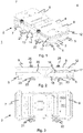
- FIGS. 1 to 6 the mechanical Unterbuchrutation 2 of a sports equipment 1, which has a support frame 3 and a vibrating plate 4 designed as a rocker.
- the carrier position 3 is parked at the bottom on rubber buffer 5, which are held by a left transverse strut 6 and a right cross strut 7.
- the rocker 4 consists of two individual plate parts 8 and 9, which are fastened on both sides to metal tubes 11 and 12. Centered on the metal tubes 11 and 12 triangular connecting pieces 13 are provided, which are mounted on a rotation axis 14.
- an electric motor 15 with a V-belt 16 is provided to reciprocate the rocker 4.
- the electric motor 15 is fixed to the support frame 4.
- a drive pulley 17 is rotated on a drive shaft 18 in rotation.
- a cam wheel 19 is provided, which brings the rocker 4 in an up and down movement (see FIG. 7 ).
- a rotary motor 20 is attached to the support frame 3, which is designed as a DC motor and an electronic control 60 (see FIG. 13 ), which can perform by a Polumledgeung both a left and a right turn.
- two fans 21 and 22 are provided, which is enclosed with a funnel-shaped cover 23 with an exhaust duct 24.
- the exhaust air duct 24 is connected to a flexible tube 25, preferably a rubber tube, which has an air-permeable aroma container 26 at its free end.
- FIGS. 7 to 9 is the substructure 2 without rocker 4 shown in a perspective view.
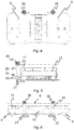
- FIG. 10 shows the sports equipment 1 with a lower cover 27 from the bottom. Rubber feet 28 are provided at the four corners of the cover. Further, air inlets 29 are provided for the fans 21 and 22 in the lower cover 27.
- FIG. 11 shows the sports equipment 1 with an upper cover 30 from the top.
- the two aroma containers 26 are guided through a circular opening 31 in the upper cover 30 to the outside.
- an operating unit 32 with a display 33 is provided between the two aroma containers 26 between the two aroma containers 26, an operating unit 32 with a display 33 is provided.
- FIG. 12 shows the sports equipment 1 in side view with the upper cover 30, the lower cover 27, the rubber feet 28 and an electrical connection 35th
- FIG. 13 shows an exploded view of the sports device 1.
- the electronic control for the rotary motor or DC motor 20 can be seen.
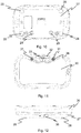
- a first eccentric weight part 40 is shown, which has a circular sector 41 with a cylindrical attachment 42 for the rotation axis 43 (see FIGS. 16 and 17 ) of the rotary motor 15 has.
- On the circular sector 41 designed as a pin stop 44 is provided.
- a second eccentric weight part 45 with a circular sector 46 and a cylindrical attachment 47 is shown. As can be seen, the second eccentric weight part 45 has a smaller dimension and thus has a lower weight than the first eccentric weight part 40.
- FIG. 16 the two eccentric weight parts 40 and 45 are mounted one above the other on the rotation axis 43 of the rotary motor 15, the first eccentric weight part 40 being fixedly arranged on the rotation axis 43 and the second eccentric weight part 45 rotatably mounted on the rotation axis 43.
- FIG. 16 illustrates the situation when the rotary motor 15 rotates to the left and the second eccentric weight part 45 is taken from the right by the stop 44.
- FIG. 17 illustrates the situation when the rotary motor 15 rotates to the right and the second eccentric weight part 45 by the imbalance 180 ° relative to the first eccentric weight part 40 is located. This can cause a change in the moment of inertia of the eccentric weight, so that when turning to the left a vibration with a higher frequency and a clockwise rotation can produce a vibration with a lower frequency.
- the aroma container 26 is shown in a perspective view, which has a metal housing 50, preferably made of stainless steel. But it can also be made of a suitable plastic such as PPE.
- the aroma container 26 has a first screen 51, which is fixed in the metal housing 40, and a second screen 52, which is designed as a hinged lid. Between the two screens 51 and 52, a gap is formed in the folded state in which a flavorant-containing medium is inserted. As a medium is a non-woven mat or the like.
- a return flap (not shown) is provided below the first screen 51.
- the second designed as a hinged lid screen 52 is closed by a permanent magnet.
Landscapes
- Health & Medical Sciences (AREA)
- Epidemiology (AREA)
- Pain & Pain Management (AREA)
- Physical Education & Sports Medicine (AREA)
- Rehabilitation Therapy (AREA)
- Life Sciences & Earth Sciences (AREA)
- Animal Behavior & Ethology (AREA)
- General Health & Medical Sciences (AREA)
- Public Health (AREA)
- Veterinary Medicine (AREA)
- Percussion Or Vibration Massage (AREA)
- Apparatuses For Generation Of Mechanical Vibrations (AREA)
Abstract
Description
- Die Erfindung betrifft ein Sportgerät mit einer Vibrationsplatte nach dem Oberbegriff des Patentanspruchs 1.
- Sportgeräte mit Vibrationsplatten für die Muskelstimulierung einer Person sind seit längerem bekannt und werden mit unterschiedlichen Antriebssystemen betrieben.
- Es gibt die sogenannten Wippgeräte mit einer um eine Mittelachse pendelnden Platte, wobei die maximale Neigung 6 bis 8 Grad beträgt. Die Platte wird angetrieben von einem Elektromotor mit Wechselstrom (AC) oder Gleichstrom (DC) mittels eine Stubstange ähnlich wie bei einer Dampflokomotive, oder mittels eines Exzenterrads oder eines Hebels mit Exzenternocke, welche die Platte einseitig nach oben drückt und dann wieder nach unten zieht. Die Vibrationen liegen bei 4 bis 20 Hz für einen DC-Motor und bis 30 Hz für einen AC-Motor. Die Wippe oder kippender Teil muss dabei ein geringes Gewicht aufweisen, da das Wippgerät ansonsten selbst ins Wanken geraten würde.
- Andererseits gibt es die sogenannten Rotationsgeräte, welche mit einem DC-Motor mit einer Drehrichtung oder mit einem AC-Motor in zwei Drehrichtungen betrieben wird. Der AC-Motor ist relativ gross und schwer (etwa 15 x 30 x 15 cm3 und mehr als 50 kg). Durch ein Exzentergewicht wird eine Unwucht erzeugt, so dass durch die Drehung des Motors eine Schwingung auf die Platte übertragen wird. Der Motor ist dabei an der Platte und nicht am untenliegenden Trägergestell befestigt. Gummipuffer sorgen dafür, dass die Platte richtig vibrieren kann.
- Aufgrund der unterschiedlichen Antriebssystemen für ein Wippgerät und für ein Rotationsgerät ist die Kombination der beiden für Sportgeräte mit einer leichteren Bauart, d.h. mit einem Gewicht von etwa 15 bis maximal 50 kg, bisher nicht bekannt.
- Es nun Aufgabe der vorliegenden Erfindung, ein Sportgerät mit einer von einer Vibrationsplatte gebildeten Wippe derart weiterzuentwickeln, dass eine grössere Kombination von Vibrationen ermöglicht wird.
- Diese Aufgabe wird durch ein Sportgerät mit einer Vibrationsplatte mit den Merkmalen des Patentanspruchs 1 gelöst.
- Das erfindungsgemässe Sportgerät ist mit einer Vibrationsplatte für die Muskelstimulierung einer Person mit einem Trägergestell, einer von der Vibrationsplatte gebildeten Wippe und einem elektrischen Motor ausgestattet, welcher an der Vibrationsplatte befestigt ist und über einen Keilriemen die Wippe auf- und abbewegt. Zusätzlich ist ein Rotationsmotor mit einer Antriebsachse und einem auf der Achse befestigten Exzentergewicht vorgesehen, wobei der Rotationsmotor links- und rechtsdrehend ausgebildet ist und das Exzentergewicht von einem auf der Achse befestigten ersten Exzentergewichtsteil und einem auf der Achse drehbaren zweiten Exzentergewichtsteilgebildet ist, wobei ein Anschlag auf dem ersten Exzentergewichtsteil vorgesehen ist, gegen welchen das zweite Exzentergewichtsteil bei der Links- oder Rechtsdrehung anschlägt.
- Die Erfindung hat den Vorteil, dass mit dem erfindungsgemässen Sportgerät verschiedene Kombinationen von Vibrationen mit einer Wippe oder durch Unwucht erzeugt werden können. Es können dabei Vibrationen im Bereich von 4 bis 50 Hz erzeugt werden, wobei die Amplitude der Wippe durch die Stehposition des Benutzers und die Rotation in einer Links- und einer Rechtsdrehung verändert werden kann.
- In einer weiteren Ausgestaltung der Erfindung gemäss Anspruch 2 ist der Rotationsmotor ein DC-Motor und ist eine elektronische Steuerung vorgesehen, welche die Links- und Rechtsdrehung des Rotationsmotors durch Polumkehrung steuert.
- In einer vorteilhaften Ausführung gemäss Anspruch 3 ist der Rotationsmotor am Trägergestell befestigt.
- In einer weiteren Ausführung gemäss Anspruch 4 ist im unteren Bereich des Trägergestells mindestens ein Ventilator vorgesehen, welcher von einer trichterförmigen Abdeckung mit einem Luftkanal umschlossen ist, wobei der Luftkanal an einem flexiblen Rohr, vorzugsweise einem Gummirohr, angeschlossen ist, welches zu einem luftdurchlässigen Aromabehälter im oberen Bereich des Sportgeräts führt.
- In einer vorteilhaften Ausgestaltung gemäss Anspruch 5 weist der Aromabehälter ein Metallgehäuse mit zwei Sieben und ein Aromastoff enthaltenden Medium zwischen den beiden Sieben auf.
- In einer weiteren Ausführung gemäss Anspruch 6 weist Metallgehäuse in Strömungsrichtung vor den Sieben ein Rückschlagventil auf.
- Vorteilhafterweise besteht der Aromastoff gemäss Anspruch 7 aus natürlichen Essenzen.
- Weitere Vorteile der Erfindung folgen aus den abhängigen Patentansprüchen und aus der nachfolgenden Beschreibung, in welcher die Erfindung anhand eines in den schematischen Zeichnungen dargestellten Ausführungsbeispieles näher erläutert wird. Es zeigt:
- Fig. 1
- die mechanische Unterkonstruktion eines Sportgerätes mit einer Vibrationsplatte,
- Fig. 2
- dasselbe Sportgerät der
Figur 1 in einer linken Seitenansicht, - Fig. 3
- dasselbe Sportgeräte der
Figur 1 in Untenansicht, - Fig. 4
- dasselbe Sportgerät der
Figur 1 in Obenansicht, - Fig. 5
- dasselbe Sportgerät der
Figur 1 in einer Frontansicht, - Fig. 6
- dasselbe Sportgerät der
Figur 1 in einer rechten Seitenansicht, - Fig. 7
- das Trägergestell des Sportgeräts der
Figur 1 ohne Vibrationsplatte, - Fig. 8
- das Trägergestell der
Figur 7 in einer linken Seitenansicht, - Fig. 9
- das Trägergestell der
Figur 7 in Obenansicht, - Fig. 10
- das Sportgerät der
Figur 1 mit einer Verschalung in Untenansicht, - Fig. 11
- das Sportgerät der
Figur 1 mit der Verschalung in Obenansicht, - Fig. 12
- das Sportgerät der
Figur 1 mit der Verschalung in Seitenansicht, - Fig. 13
- eine Explosionsdarstellung des Sportgeräts,
- Fig. 14
- ein erstes Exzentergewichsteil,
- Fig. 15
- ein zweites Exzentergewichtsteil,
- Fig. 16
- die zwei Exzentergewichtsteile bei einer Linksdrehung,
- Fig. 17
- die zwei Exzentergewichtsteile bei einer Rechtsdrehung, und
- Fig. 18
- einen als Metallgehäuse ausgebildeten Aromabehälter.
- In den Figuren sind für dieselben Elemente jeweils dieselben Bezugszeichen verwendet worden und erstmalige Erklärungen betreffen alle Figuren, wenn nicht ausdrücklich anders erwähnt.
- In den
Figuren 1 bis 6 ist die mechanische Unterkunstruktion 2 eines Sportgerätes 1, welche ein Trägergestell 3 und eine als Wippe ausgebildete Vibrationsplatte 4 aufweist. Das Trägergestellt 3 ist unten auf Gummipuffer 5 abgestellt, welche von einer linken Querstrebe 6 und einer rechten Querstrebe 7 gehalten werden. Die Wippe 4 besteht aus zwei einzelnen Plattenteile 8 und 9, die beidseitig auf Metallrohren 11 und 12 befestigt sind. Mittig sind an den Metallrohren 11 und 12 dreieckige Verbindungsstücke 13 vorgesehen, welche auf einer Drehachse 14 befestigt sind. - Um die Wippe 4 hin- und herzubewegen ist ein elektrischer Motor 15 mit einem Keilriemen 16 vorgesehen. Der elektrische Motor 15 ist am Trägergestell 4 befestigt. Mit dem Keilriemen 16 wird eine Antreibsscheibe 17 auf einer Antriebswelle 18 in Drehung versetzt. Auf der Antriebswelle 17 ist ein Nockenrad 19 vorgesehen, welche die Wippe 4 in einer Auf- und Abbewegung bringt (siehe
Figur 7 ). Ferner ist ein Rotationsmotor 20 am Trägergestell 3 befestigt, welcher als DC-Motor ausgebildet ist und eine elektronische Steuerung 60 (sieheFigur 13 ) aufweist, welche durch eine Polumkehrung sowohl ein Links- als eine Rechtsdrehung ausführen kann. - Im unteren Bereich des Trägergestells 3 sind zwei Ventilatoren 21 und 22 vorgesehen, die mit einer trichterförmigen Abdeckung 23 mit einem Abluftkanal 24 umschlossen ist. Der Abluftkanal 24 ist an einem flexiblen Rohr 25, vorzugsweise einem Gummirohr, angeschlossen, welches an ihrem freien Ende ein luftdurchlässigen Aromabehälter 26 aufweist.
- In den
Figuren 7 bis 9 ist die Unterkonstruktion 2 ohne Wippe 4 in einer perspektiven Darstellung gezeigt. -
Figur 10 zeigt das Sportgerät 1 mit einer unteren Abdeckung 27 von der Unterseite. An den vier Ecken der Abdeckung sind Gummifüsse 28 vorgesehen. Ferner sind Lufteinlässe 29 für die Ventilatoren 21 und 22 in der unteren Abdeckung 27 vorgesehen. -
Figur 11 zeigt das Sportgerät 1 mit einer oberen Abdeckung 30 von der Oberseite. Wie ersichtlich sind die beiden Aromabehälter 26 durch eine kreisrunde Öffnung 31 in der oberen Abdeckung 30 nach aussen geführt. Zwischen den beiden Aromabehälter 26 ist eine Bedienungseinheit 32 mit einer Anzeige 33 vorgesehen. -
Figur 12 zeigt das Sportgerät 1 in Seitenansicht mit der oberen Abdeckung 30, der unteren Abdeckung 27, den Gummifüssen 28 und einem elektrischen Anschluss 35. -
Figur 13 zeigt eine Explosionszeichnung des Sportgeräts 1. Neben den Elementen der vorangehenden Figuren ist hier die elektronische Steuerung für den Rotationsmotor oder DC-Motor 20 ersichtlich. - In
Figur 14 ist ein erstes Exzentergewichtsteil 40 gezeigt, das einen Kreissektor 41 mit einer zylindrischen Befestigung 42 für die Drehachse 43 (sieheFiguren 16 und 17 ) des Rotationsmotors 15 aufweist. Auf dem Kreissektor 41 ist ein als Stift ausgebildeter Anschlag 44 vorgesehen. InFigur 15 ist ein zweites Exzentergewichtsteil 45 mit einem Kreissektor 46 und einer zylindrischen Befestigung 47 gezeigt. Wie ersichtlich weist das zweite Exzentergewichtsteil 45 eine geringere Dimension auf und hat somit ein geringeres Gewicht als das erste Exzentergewichtsteil 40. - In
Figur 16 sind die beiden Exzentergewichtsteile 40 und 45 übereinander auf der Drehachse 43 des Rotationsmotors 15 befestigt, wobei das erste Exzentergewichtsteil 40 fest auf der Drehachse 43 und das zweite Exzentergewichtsteil 45 drehbar auf der Drehachse 43 angeordnet ist.Figur 16 stellt die Situation dar, wenn der Rotationsmotor 15 nach links dreht und das zweite Exzentergewichtsteil 45 von rechts durch den Anschlag 44 mitgenommen wird.Figur 17 stellt die Situation dar, wenn der Rotationsmotor 15 nach rechts dreht und das zweite Exzentergewichtsteil 45 durch die Unwucht um 180° gegenüber dem ersten Exzentergewichtsteil 40 liegt. Damit kann man eine Änderung des Trägheitsmoment des Exzentergewichts bewirken, so dass bei einer Linksdrehung eine Vibration mit einer höheren Frequenz und bei einer Rechtsdrehung eine Vibration mit einer tieferen Frequenz erzeugen kann. - Da der elektrische Motor 15 und der Rotationsmotor 20 auf dem Trägergestell 3 befestigt sind, ist das für die Unwucht des Rotationsmotors 20 notwendige grössere Gewicht wieder gewährleistet, damit der Körper der übenden Person nachhaltig vibrieren zu können.
- Mit dem oben geschriebenen Sportgerät 1 können nun verschiedene Kombinationen von Vibrationen mit einer Wippe oder durch Unwucht erzeugt werden. Es können dabei Vibrationen im Bereich von 4 bis 50 Hz erzeugt werden, wobei die Amplitude der Wippe durch die Stehposition des Benutzers und die Rotation in einer Links- und einer Rechtsdrehung verändert werden kann.
- In
Figur 17 ist der Aromabehälter 26 in einer perspektivischen Darstellung gezeigt, der ein Metallgehäuse 50 aufweist, vorzugsweise aus Edelstahl. Es kann aber auch aus einem geeigneten Kunststoff wie PPE hergestellt sein. Der Aromabehälter 26 weist ein erstes Sieb 51 auf, das im Metallgehäuse 40 befestigt ist, und ein zweites Sieb 52, das als Klappdeckel ausgebildet ist. Zwischen den beiden Sieben 51 und 52 wird in zugeklappten Zustand ein Zwischenraum gebildet, in welchem ein Aromastoff enthaltendes Medium eingelegt ist. Als Medium eignet sich eine Vliesmatte oder dergleichen. Um zu verhindern, dass bei abgestellten Ventilator 21, 22 die Aromastoffe in den Innenraum des Sportgeräts eindringen können, ist eine - nicht dargestellte - Rückflussklappe unterhalb des ersten Siebes 51 vorgesehen. Das zweite als Klappdeckel ausgebildete Sieb 52 wird mit einem Permanentmagnet geschlossen.
Claims (7)
- Sportgerät (1) mit einer Vibrationsplatte (4) für die Muskelstimulierung einer Person mit einem Trägergestell (3), einer von der Vibrationsplatte gebildeten Wippe und einem elektrischen Motor (15), welcher an der Vibrationsplatte befestigt ist und über einen Keilriemen (16) die Wippe auf- und abbewegt, dadurch gekennzeichnet, dass zusätzlich ein Rotationsmotor (20) mit einer Antriebsachse (33) und einem auf der Achse befestigten Exzentergewicht vorgesehen ist, wobei der Rotationsmotor (20) links- und rechtsdrehend ausgebildet ist und das Exzentergewicht von einem auf der Achse befestigten ersten Exzentergewichtsteil (40) und einem auf der Achse drehbaren zweiten Exzentergewichtsteil (35) gebildet ist, wobei ein Anschlag (44) auf dem ersten Exzentergewichtsteil (40) vorgesehen ist, gegen welchen das zweite Exzentergewichtsteil (45) bei der Links- oder Rechtsdrehung anschlägt.
- Sportgerät (1) nach Anspruch 1, dadurch gekennzeichnet, dass der Rotationsmotor (20) ein DC-Motor ist und eine elektronische Steuerung vorgesehen ist, welche die Links- und Rechtsdrehung des Rotationsmotors durch Polumkehrung steuert.
- Sportgerät (1) nach Anspruch 1 oder 2, dadurch gekennzeichnet, dass der Rotationsmotor (20) am Trägergestell (3) befestigt ist.
- Sportgerät (1) nach einem der Ansprüche 1 bis 3, dadurch gekennzeichnet, dass im unteren Bereich des Trägergestells (3) mindestens ein Ventilator (21, 22) vorgesehen ist, welcher von einer trichterförmigen Abdeckung (23) mit einem Luftkanal (24) umschlossen ist, wobei der Luftkanal (24) an einem flexiblen Rohr (25), vorzugsweise einem Gummirohr, angeschlossen ist, welches zu einem luftdurchlässigen Aromabehälter (26) im oberen Bereich des Sportgeräts führt.
- Sportgerät (1) nach Anspruch 4, dadurch gekennzeichnet, dass der Aromabehälter (26) ein Metallgehäuse (50) mit zwei Sieben (51, 54) und ein Aromastoff enthaltenden Medium zwischen den beiden Sieben aufweist.
- Sportgerät nach Anspruch 5, dadurch gekennzeichnet, dass das Metallgehäuse (50) in Strömungsrichtung vor den Sieben ein Rückschlagventil aufweist.
- Sportgerät nach Anspruch 6, dadurch gekennzeichnet, dass der Aromastoff aus natürlichen Essenzen besteht.
Applications Claiming Priority (1)
| Application Number | Priority Date | Filing Date | Title |
|---|---|---|---|
| CH942018 | 2018-01-28 |
Publications (2)
| Publication Number | Publication Date |
|---|---|
| EP3517090A1 true EP3517090A1 (de) | 2019-07-31 |
| EP3517090B1 EP3517090B1 (de) | 2021-08-18 |
Family
ID=65443626
Family Applications (1)
| Application Number | Title | Priority Date | Filing Date |
|---|---|---|---|
| EP19153991.5A Active EP3517090B1 (de) | 2018-01-28 | 2019-01-28 | Sportgerät mit einer vibrationsplatte |
Country Status (1)
| Country | Link |
|---|---|
| EP (1) | EP3517090B1 (de) |
Citations (5)
| Publication number | Priority date | Publication date | Assignee | Title |
|---|---|---|---|---|
| US20050131319A1 (en) * | 2003-09-19 | 2005-06-16 | Der Meer Guus V. | Body vibration apparatus |
| EP1649845A1 (de) * | 2004-10-25 | 2006-04-26 | Heat-Wave AG | Gerät zur Stimulation des menschlichen Körpers mittels Vibrationen |
| US20090086569A1 (en) * | 2007-09-28 | 2009-04-02 | Tonic Fitness Technology, Inc. | Amplitude change-over device for a body vibration machine |
| US20100105524A1 (en) * | 2007-02-28 | 2010-04-29 | Philippe Laurent | Vibrating plate apparatus for muscular toning |
| US20120061049A1 (en) * | 2010-09-09 | 2012-03-15 | Micucci Michael S | System and Method for Delivering Temperature-Controlled Airflow Through Vending Module |
-
2019
- 2019-01-28 EP EP19153991.5A patent/EP3517090B1/de active Active
Patent Citations (5)
| Publication number | Priority date | Publication date | Assignee | Title |
|---|---|---|---|---|
| US20050131319A1 (en) * | 2003-09-19 | 2005-06-16 | Der Meer Guus V. | Body vibration apparatus |
| EP1649845A1 (de) * | 2004-10-25 | 2006-04-26 | Heat-Wave AG | Gerät zur Stimulation des menschlichen Körpers mittels Vibrationen |
| US20100105524A1 (en) * | 2007-02-28 | 2010-04-29 | Philippe Laurent | Vibrating plate apparatus for muscular toning |
| US20090086569A1 (en) * | 2007-09-28 | 2009-04-02 | Tonic Fitness Technology, Inc. | Amplitude change-over device for a body vibration machine |
| US20120061049A1 (en) * | 2010-09-09 | 2012-03-15 | Micucci Michael S | System and Method for Delivering Temperature-Controlled Airflow Through Vending Module |
Also Published As
| Publication number | Publication date |
|---|---|
| EP3517090B1 (de) | 2021-08-18 |
Similar Documents
| Publication | Publication Date | Title |
|---|---|---|
| EP1827350A1 (de) | Gerät zur stimulation des menschlichen körpers mittels vibrationen | |
| CH346643A (de) | Elektrischer Ventilator | |
| EP2010121B1 (de) | Trainingsgerät | |
| EP2910312A1 (de) | Schwinganordnung für einen Rütteltisch oder eine Siebvorrichtung | |
| DE202009006985U1 (de) | Trainingsvorrichtung | |
| DE202014102450U1 (de) | Tretgerät zum Abnehmen des Körpergewichts | |
| EP1292366B1 (de) | Vorrichtung zur therapie und zum trainieren der gelenke des menschlichen körpers | |
| EP3517090B1 (de) | Sportgerät mit einer vibrationsplatte | |
| DE3638359A1 (de) | Vorrichtung zur vibrationstherapie | |
| DE102009006330A1 (de) | Antrieb für Vibrationsplatten | |
| DE69714515T2 (de) | Übungsgerät für Trainung der Bauchmuskulator | |
| US2579002A (en) | Mechanical vibrating screen | |
| DE3723662A1 (de) | Vorrichtung zur vibrationstherapie | |
| DE102007030582A1 (de) | Vibratorvorrichtung | |
| EP1813245A1 (de) | Gerät zur Stimulation des menschlichen Körpers mittels Vibrationen | |
| DE615459C (de) | Durch unausgeglichene umlaufende Massen angetriebenes Schwingsieb | |
| DE3326801A1 (de) | Extensionsgeraet | |
| DE155306C (de) | ||
| DE435143C (de) | Klassiervorrichtung, deren Sieb mit einer darunter befindlichen Stuetze und einer Ein-richtung zum Erschuettern des Siebes zusammenwirkt und an der Stuetze unbefestigt ist | |
| DE29818001U1 (de) | Trainingsgerät | |
| DE2250262C3 (de) | Elektrisches Massagegerät | |
| DE2407730C3 (de) | Plattenrüttler für die Verdichtung des Baugrundes o.dgl | |
| DE102017114425A1 (de) | Elliptischer Stepper | |
| DE1248445B (de) | Siebvorrichtung, insbesondere fuer feuchtes oder klebriges Siebgut | |
| DE202007004456U1 (de) | Variable Drehscheibe |
Legal Events
| Date | Code | Title | Description |
|---|---|---|---|
| PUAI | Public reference made under article 153(3) epc to a published international application that has entered the european phase |
Free format text: ORIGINAL CODE: 0009012 |
|
| STAA | Information on the status of an ep patent application or granted ep patent |
Free format text: STATUS: THE APPLICATION HAS BEEN PUBLISHED |
|
| AK | Designated contracting states |
Kind code of ref document: A1 Designated state(s): AL AT BE BG CH CY CZ DE DK EE ES FI FR GB GR HR HU IE IS IT LI LT LU LV MC MK MT NL NO PL PT RO RS SE SI SK SM TR |
|
| AX | Request for extension of the european patent |
Extension state: BA ME |
|
| STAA | Information on the status of an ep patent application or granted ep patent |
Free format text: STATUS: REQUEST FOR EXAMINATION WAS MADE |
|
| 17P | Request for examination filed |
Effective date: 20200128 |
|
| RBV | Designated contracting states (corrected) |
Designated state(s): AL AT BE BG CH CY CZ DE DK EE ES FI FR GB GR HR HU IE IS IT LI LT LU LV MC MK MT NL NO PL PT RO RS SE SI SK SM TR |
|
| GRAP | Despatch of communication of intention to grant a patent |
Free format text: ORIGINAL CODE: EPIDOSNIGR1 |
|
| STAA | Information on the status of an ep patent application or granted ep patent |
Free format text: STATUS: GRANT OF PATENT IS INTENDED |
|
| GRAJ | Information related to disapproval of communication of intention to grant by the applicant or resumption of examination proceedings by the epo deleted |
Free format text: ORIGINAL CODE: EPIDOSDIGR1 |
|
| STAA | Information on the status of an ep patent application or granted ep patent |
Free format text: STATUS: REQUEST FOR EXAMINATION WAS MADE |
|
| INTG | Intention to grant announced |
Effective date: 20210112 |
|
| INTC | Intention to grant announced (deleted) | ||
| GRAP | Despatch of communication of intention to grant a patent |
Free format text: ORIGINAL CODE: EPIDOSNIGR1 |
|
| STAA | Information on the status of an ep patent application or granted ep patent |
Free format text: STATUS: GRANT OF PATENT IS INTENDED |
|
| INTG | Intention to grant announced |
Effective date: 20210316 |
|
| GRAS | Grant fee paid |
Free format text: ORIGINAL CODE: EPIDOSNIGR3 |
|
| GRAA | (expected) grant |
Free format text: ORIGINAL CODE: 0009210 |
|
| STAA | Information on the status of an ep patent application or granted ep patent |
Free format text: STATUS: THE PATENT HAS BEEN GRANTED |
|
| AK | Designated contracting states |
Kind code of ref document: B1 Designated state(s): AL AT BE BG CH CY CZ DE DK EE ES FI FR GB GR HR HU IE IS IT LI LT LU LV MC MK MT NL NO PL PT RO RS SE SI SK SM TR |
|
| REG | Reference to a national code |
Ref country code: GB Ref legal event code: FG4D Free format text: NOT ENGLISH |
|
| REG | Reference to a national code |
Ref country code: CH Ref legal event code: EP |
|
| REG | Reference to a national code |
Ref country code: DE Ref legal event code: R096 Ref document number: 502019002055 Country of ref document: DE |
|
| REG | Reference to a national code |
Ref country code: IE Ref legal event code: FG4D Free format text: LANGUAGE OF EP DOCUMENT: GERMAN Ref country code: AT Ref legal event code: REF Ref document number: 1420962 Country of ref document: AT Kind code of ref document: T Effective date: 20210915 |
|
| REG | Reference to a national code |
Ref country code: LT Ref legal event code: MG9D |
|
| REG | Reference to a national code |
Ref country code: NL Ref legal event code: MP Effective date: 20210818 |
|
| PG25 | Lapsed in a contracting state [announced via postgrant information from national office to epo] |
Ref country code: RS Free format text: LAPSE BECAUSE OF FAILURE TO SUBMIT A TRANSLATION OF THE DESCRIPTION OR TO PAY THE FEE WITHIN THE PRESCRIBED TIME-LIMIT Effective date: 20210818 Ref country code: SE Free format text: LAPSE BECAUSE OF FAILURE TO SUBMIT A TRANSLATION OF THE DESCRIPTION OR TO PAY THE FEE WITHIN THE PRESCRIBED TIME-LIMIT Effective date: 20210818 Ref country code: FI Free format text: LAPSE BECAUSE OF FAILURE TO SUBMIT A TRANSLATION OF THE DESCRIPTION OR TO PAY THE FEE WITHIN THE PRESCRIBED TIME-LIMIT Effective date: 20210818 Ref country code: ES Free format text: LAPSE BECAUSE OF FAILURE TO SUBMIT A TRANSLATION OF THE DESCRIPTION OR TO PAY THE FEE WITHIN THE PRESCRIBED TIME-LIMIT Effective date: 20210818 Ref country code: HR Free format text: LAPSE BECAUSE OF FAILURE TO SUBMIT A TRANSLATION OF THE DESCRIPTION OR TO PAY THE FEE WITHIN THE PRESCRIBED TIME-LIMIT Effective date: 20210818 Ref country code: NO Free format text: LAPSE BECAUSE OF FAILURE TO SUBMIT A TRANSLATION OF THE DESCRIPTION OR TO PAY THE FEE WITHIN THE PRESCRIBED TIME-LIMIT Effective date: 20211118 Ref country code: PT Free format text: LAPSE BECAUSE OF FAILURE TO SUBMIT A TRANSLATION OF THE DESCRIPTION OR TO PAY THE FEE WITHIN THE PRESCRIBED TIME-LIMIT Effective date: 20211220 Ref country code: BG Free format text: LAPSE BECAUSE OF FAILURE TO SUBMIT A TRANSLATION OF THE DESCRIPTION OR TO PAY THE FEE WITHIN THE PRESCRIBED TIME-LIMIT Effective date: 20211118 Ref country code: LT Free format text: LAPSE BECAUSE OF FAILURE TO SUBMIT A TRANSLATION OF THE DESCRIPTION OR TO PAY THE FEE WITHIN THE PRESCRIBED TIME-LIMIT Effective date: 20210818 |
|
| PG25 | Lapsed in a contracting state [announced via postgrant information from national office to epo] |
Ref country code: PL Free format text: LAPSE BECAUSE OF FAILURE TO SUBMIT A TRANSLATION OF THE DESCRIPTION OR TO PAY THE FEE WITHIN THE PRESCRIBED TIME-LIMIT Effective date: 20210818 Ref country code: LV Free format text: LAPSE BECAUSE OF FAILURE TO SUBMIT A TRANSLATION OF THE DESCRIPTION OR TO PAY THE FEE WITHIN THE PRESCRIBED TIME-LIMIT Effective date: 20210818 Ref country code: GR Free format text: LAPSE BECAUSE OF FAILURE TO SUBMIT A TRANSLATION OF THE DESCRIPTION OR TO PAY THE FEE WITHIN THE PRESCRIBED TIME-LIMIT Effective date: 20211119 |
|
| PG25 | Lapsed in a contracting state [announced via postgrant information from national office to epo] |
Ref country code: NL Free format text: LAPSE BECAUSE OF FAILURE TO SUBMIT A TRANSLATION OF THE DESCRIPTION OR TO PAY THE FEE WITHIN THE PRESCRIBED TIME-LIMIT Effective date: 20210818 |
|
| PG25 | Lapsed in a contracting state [announced via postgrant information from national office to epo] |
Ref country code: DK Free format text: LAPSE BECAUSE OF FAILURE TO SUBMIT A TRANSLATION OF THE DESCRIPTION OR TO PAY THE FEE WITHIN THE PRESCRIBED TIME-LIMIT Effective date: 20210818 |
|
| REG | Reference to a national code |
Ref country code: DE Ref legal event code: R097 Ref document number: 502019002055 Country of ref document: DE |
|
| PG25 | Lapsed in a contracting state [announced via postgrant information from national office to epo] |
Ref country code: SM Free format text: LAPSE BECAUSE OF FAILURE TO SUBMIT A TRANSLATION OF THE DESCRIPTION OR TO PAY THE FEE WITHIN THE PRESCRIBED TIME-LIMIT Effective date: 20210818 Ref country code: SK Free format text: LAPSE BECAUSE OF FAILURE TO SUBMIT A TRANSLATION OF THE DESCRIPTION OR TO PAY THE FEE WITHIN THE PRESCRIBED TIME-LIMIT Effective date: 20210818 Ref country code: RO Free format text: LAPSE BECAUSE OF FAILURE TO SUBMIT A TRANSLATION OF THE DESCRIPTION OR TO PAY THE FEE WITHIN THE PRESCRIBED TIME-LIMIT Effective date: 20210818 Ref country code: EE Free format text: LAPSE BECAUSE OF FAILURE TO SUBMIT A TRANSLATION OF THE DESCRIPTION OR TO PAY THE FEE WITHIN THE PRESCRIBED TIME-LIMIT Effective date: 20210818 Ref country code: CZ Free format text: LAPSE BECAUSE OF FAILURE TO SUBMIT A TRANSLATION OF THE DESCRIPTION OR TO PAY THE FEE WITHIN THE PRESCRIBED TIME-LIMIT Effective date: 20210818 Ref country code: AL Free format text: LAPSE BECAUSE OF FAILURE TO SUBMIT A TRANSLATION OF THE DESCRIPTION OR TO PAY THE FEE WITHIN THE PRESCRIBED TIME-LIMIT Effective date: 20210818 |
|
| PLBE | No opposition filed within time limit |
Free format text: ORIGINAL CODE: 0009261 |
|
| STAA | Information on the status of an ep patent application or granted ep patent |
Free format text: STATUS: NO OPPOSITION FILED WITHIN TIME LIMIT |
|
| 26N | No opposition filed |
Effective date: 20220519 |
|
| PG25 | Lapsed in a contracting state [announced via postgrant information from national office to epo] |
Ref country code: IT Free format text: LAPSE BECAUSE OF FAILURE TO SUBMIT A TRANSLATION OF THE DESCRIPTION OR TO PAY THE FEE WITHIN THE PRESCRIBED TIME-LIMIT Effective date: 20210818 |
|
| PG25 | Lapsed in a contracting state [announced via postgrant information from national office to epo] |
Ref country code: SI Free format text: LAPSE BECAUSE OF FAILURE TO SUBMIT A TRANSLATION OF THE DESCRIPTION OR TO PAY THE FEE WITHIN THE PRESCRIBED TIME-LIMIT Effective date: 20210818 Ref country code: MC Free format text: LAPSE BECAUSE OF FAILURE TO SUBMIT A TRANSLATION OF THE DESCRIPTION OR TO PAY THE FEE WITHIN THE PRESCRIBED TIME-LIMIT Effective date: 20210818 |
|
| REG | Reference to a national code |
Ref country code: BE Ref legal event code: MM Effective date: 20220131 |
|
| PG25 | Lapsed in a contracting state [announced via postgrant information from national office to epo] |
Ref country code: LU Free format text: LAPSE BECAUSE OF NON-PAYMENT OF DUE FEES Effective date: 20220128 |
|
| PG25 | Lapsed in a contracting state [announced via postgrant information from national office to epo] |
Ref country code: FR Free format text: LAPSE BECAUSE OF NON-PAYMENT OF DUE FEES Effective date: 20220131 Ref country code: BE Free format text: LAPSE BECAUSE OF NON-PAYMENT OF DUE FEES Effective date: 20220131 |
|
| PG25 | Lapsed in a contracting state [announced via postgrant information from national office to epo] |
Ref country code: IE Free format text: LAPSE BECAUSE OF NON-PAYMENT OF DUE FEES Effective date: 20220128 |
|
| GBPC | Gb: european patent ceased through non-payment of renewal fee |
Effective date: 20230128 |
|
| PG25 | Lapsed in a contracting state [announced via postgrant information from national office to epo] |
Ref country code: GB Free format text: LAPSE BECAUSE OF NON-PAYMENT OF DUE FEES Effective date: 20230128 |
|
| REG | Reference to a national code |
Ref country code: DE Ref legal event code: R081 Ref document number: 502019002055 Country of ref document: DE Owner name: BODYSWISS AG, CH Free format text: FORMER OWNER: SWISSPLATE GMBH, BREMGARTEN, CH |
|
| REG | Reference to a national code |
Ref country code: AT Ref legal event code: PC Ref document number: 1420962 Country of ref document: AT Kind code of ref document: T Owner name: BODYSWISS AG, CH Effective date: 20240105 |
|
| PG25 | Lapsed in a contracting state [announced via postgrant information from national office to epo] |
Ref country code: MK Free format text: LAPSE BECAUSE OF FAILURE TO SUBMIT A TRANSLATION OF THE DESCRIPTION OR TO PAY THE FEE WITHIN THE PRESCRIBED TIME-LIMIT Effective date: 20210818 Ref country code: CY Free format text: LAPSE BECAUSE OF FAILURE TO SUBMIT A TRANSLATION OF THE DESCRIPTION OR TO PAY THE FEE WITHIN THE PRESCRIBED TIME-LIMIT Effective date: 20210818 |
|
| PG25 | Lapsed in a contracting state [announced via postgrant information from national office to epo] |
Ref country code: HU Free format text: LAPSE BECAUSE OF FAILURE TO SUBMIT A TRANSLATION OF THE DESCRIPTION OR TO PAY THE FEE WITHIN THE PRESCRIBED TIME-LIMIT; INVALID AB INITIO Effective date: 20190128 |
|
| PG25 | Lapsed in a contracting state [announced via postgrant information from national office to epo] |
Ref country code: MT Free format text: LAPSE BECAUSE OF FAILURE TO SUBMIT A TRANSLATION OF THE DESCRIPTION OR TO PAY THE FEE WITHIN THE PRESCRIBED TIME-LIMIT Effective date: 20210818 |
|
| PG25 | Lapsed in a contracting state [announced via postgrant information from national office to epo] |
Ref country code: TR Free format text: LAPSE BECAUSE OF FAILURE TO SUBMIT A TRANSLATION OF THE DESCRIPTION OR TO PAY THE FEE WITHIN THE PRESCRIBED TIME-LIMIT Effective date: 20210818 |
|
| REG | Reference to a national code |
Ref country code: CH Ref legal event code: U11 Free format text: ST27 STATUS EVENT CODE: U-0-0-U10-U11 (AS PROVIDED BY THE NATIONAL OFFICE) Effective date: 20260201 |
|
| PGFP | Annual fee paid to national office [announced via postgrant information from national office to epo] |
Ref country code: DE Payment date: 20260120 Year of fee payment: 8 |
|
| PGFP | Annual fee paid to national office [announced via postgrant information from national office to epo] |
Ref country code: AT Payment date: 20260119 Year of fee payment: 8 |
|
| PGFP | Annual fee paid to national office [announced via postgrant information from national office to epo] |
Ref country code: CH Payment date: 20260201 Year of fee payment: 8 |