EP3517007A1 - Wc-garnitur mit klappbarem teil - Google Patents
Wc-garnitur mit klappbarem teil Download PDFInfo
- Publication number
- EP3517007A1 EP3517007A1 EP18153799.4A EP18153799A EP3517007A1 EP 3517007 A1 EP3517007 A1 EP 3517007A1 EP 18153799 A EP18153799 A EP 18153799A EP 3517007 A1 EP3517007 A1 EP 3517007A1
- Authority
- EP
- European Patent Office
- Prior art keywords
- toilet
- rotation
- stop
- rotation stop
- mounting
- Prior art date
- Legal status (The legal status is an assumption and is not a legal conclusion. Google has not performed a legal analysis and makes no representation as to the accuracy of the status listed.)
- Granted
Links
Images
Classifications
-
- A—HUMAN NECESSITIES
- A47—FURNITURE; DOMESTIC ARTICLES OR APPLIANCES; COFFEE MILLS; SPICE MILLS; SUCTION CLEANERS IN GENERAL
- A47K—SANITARY EQUIPMENT; ACCESSORIES THEREFOR, e.g. TOILET ACCESSORIES
- A47K13/00—Seats or covers for all kinds of closets
- A47K13/12—Hinges
-
- A—HUMAN NECESSITIES
- A47—FURNITURE; DOMESTIC ARTICLES OR APPLIANCES; COFFEE MILLS; SPICE MILLS; SUCTION CLEANERS IN GENERAL
- A47K—SANITARY EQUIPMENT; ACCESSORIES THEREFOR, e.g. TOILET ACCESSORIES
- A47K13/00—Seats or covers for all kinds of closets
- A47K13/10—Devices for raising and lowering ; Collapsible or rotating seats or covers
Definitions
- the present invention relates to a toilet set for a toilet (water closet).
- Toilets regularly have a toilet body with a toilet bowl, which is made of ceramic in many cases.
- hinged parts are mounted on it in most cases, namely toilet seats or toilet lid or both.
- a toilet seat is used by the user for sitting and a toilet lid for closing the toilet bowl, which usually also a toilet seat is mitabpen.
- the hinged part is rotatably held on at least one mounting part on the toilet body.
- a folding toilet seat or a folding toilet lid referred to as a toilet set, which, as just mentioned, not necessarily a toilet lid must be provided and therefore not a so-called flat fitting is mentioned.
- the folding part of this gets into a usually slightly beyond a vertical position lying position in which the hinged part rests against a wall on or before the toilet is mounted, or against another toilet part.
- a toilet seat and a toilet lid are provided, the toilet seat when folding on or in the already raised toilet lid come to rest.
- it may come to rest on a provided for a shower facility construction in the rear (ie near the wall) part of the toilet, if it is a shower toilet.
- the invention has for its object to provide a toilet set and a toilet with such a toilet seat, which have improved performance characteristics.
- a toilet set for mounting on a toilet body with a toilet bowl
- which toilet set has: a mountable on the toilet body and on it up and down foldable part and a mounting part, for mounting the hinged part is designed on the toilet body and rotatably holds the hinged part, wherein the hinged part and the mounting part are connected via a hinge, characterized in that in a rotational axis of the rotary joint surrounding part of the toilet set a rotation stop to limit the Folding movement of the hinged part is provided, as well as by a toilet equipped therewith.
- a rotation stop for the folding movement is provided according to the invention, this rotation stop being provided in a part surrounding the axis of rotation of the folding movement.
- the rotation stop can ensure the position limit for the folding movement and thus avoid an undesired collision.
- the rotation stop is provided in a part of the toilet set, which surrounds the axis of rotation.
- a part can, for. B. concentric to the axis of rotation and be designed substantially cylindrical, of which in the case of the mounting part foot down or in the case of a toilet seat or toilet cover then the (with respect to the axis of rotation) distal areas more or less radially.
- This arrangement of the rotation stopper allows a depending on the desire and need visually concealed, protected against contamination, easy to clean, with respect to injury (pinching) uncritical and / or in a practical way with other parts, such as the swivel joint, integrated design.
- the rotation stop is thus preferably concealed in terms of visibility, cleaning and / or accessibility.
- the toilet lid can be stopped by the rotation stop before hitting the wall, thus avoiding the previously described impairments.
- a preferred variant of the invention is directed to a toilet lid as a hinged part, that is, on a toilet lid set with at least one lid (and preferably also a seat).
- a rotation stop is useful and advantageous for a folding seat, the collision described in the case of a toilet cover is usually more disadvantageous. It is then a good visible surface (even with the toilet closed) of the cover affected and also another toilet part, such as a shower enclosure, or just the mentioned wall behind the toilet.
- Suitable dampers may have an approximately cylindrical and symmetrical shape to the axis of rotation and be installed in a similar manner in a part surrounding the axis of rotation of the hinged part or the mounting part as the rotation stop. Via a rotary damper, the folding movement can be additionally damped, so that the collision with the rotation stop takes place somewhat braked.
- rotary dampers have already been provided in the prior art, in order to prevent too hard striking z. As a toilet lid to avoid a wall, but could not really prevent, especially if z. B. children a bit violent with a toilet handled.
- a rotary damper only for damping the lowering movement of the hinged part, at least in the vicinity of the rotation stopper according to the invention (and possibly another rotary damper at another point).
- a particularly advantageous embodiment provides in combination with a rotary damper a sleeve-like configuration of one of the two pivot bearing parts, which belong to the rotation stop.
- a rotary damper a sleeve-like configuration of one of the two pivot bearing parts, which belong to the rotation stop.
- a further preferred embodiment provides that a part of the rotation stopper, in particular the sleeve is formed from a hinge part, that is, from one of the parts, which cause the hinged mounting of the or another folding Garnit concernss and rotate against each other.
- Such hinge parts can then z. B. by introducing suitable projections simultaneously (ie in one piece) are designed as a rotation stop. This ensures a particularly simple and economical realization of the invention. In the exemplary embodiment, this applies concretely to a part of the rotary joint of a further hinged part, namely a seat with a rotation stop acting on a cover.
- the rotation stopper is multiple, in particular double, present.
- this can have the advantage of a distribution of the occurring forces.
- the accommodation of the rotary damper according to the invention relatively close to the axis of rotation inevitably results in relatively short lever arms, which is why this aspect can be relevant in particular in the case of a low-cost design in plastic (eg injection molding).
- the advantage may be in the foreground to achieve a rotationally symmetrical design, the z. For example, in the case of a two-fold symmetry, a permutation of "top” and "bottom” or of "left” and "right” is permitted.
- the repetition of the rotation stop can be done along a revolution about the axis of rotation of the folding movement, so that z. B. in a twofold symmetry, a rotation stop in opposite position to the other (with respect to this circulation) is.
- a further preferred embodiment of the invention which is also shown as a precaution regardless of the specific arrangement in the rotational axis surrounding part of the folding part or the mounting part according to claim 1, but optionally in conjunction with all other features of the disclosure, relates to a snap mechanism.
- the rotation stop is an advantage, because with a little impetuous handling of toilet covers (or seats) is to be expected by children, this can also mean that these out of cockiness or ignorance z. B. press the toilet lid over the end stop defined by the rotation stop addition. In this case, so the snap mechanism to prevent damage to the rotation stop and possibly pivot bearing. Since in many cases there will be only a short distance to another limitation, such as to the wall, at the same time major damage to the toilet lid or toilet seat is not necessarily expected.
- one of the stop elements may be elastically held and due to this elastic support dodge, such as by an elastic arm which extends in a mosachsensenkrechten section approximately in the circumferential direction and thereby covers a partial circumference (see embodiment).
- an elastic arm which extends in a mosachsensenkrechten section approximately in the circumferential direction and thereby covers a partial circumference (see embodiment).
- z. B. a substantially radially outwardly or inwardly projecting projection can be provided.
- Such an arm can z. B. can be realized low in the aforementioned sleeve.
- the Matterschnappfunktion can promote this by one of the directly abutting stop surfaces of the rotation stop has a corresponding oblique orientation to the direction of this contact and thus can apply a corresponding elastic force according to the principle of the inclined plane.
- a snap-back option is preferably provided. This can be made after snapping over the original functional state again, so z. B. stop elements are again moved along each other to get into the actual rotation stop causing relative position to each other.
- an inclined surface may also be provided on suitable abutment surfaces, wherein this abutment surface may have a significantly different inclination than the aforementioned, so that smaller forces are sufficient for the snapback.
- the invention further relates to a complete toilet with a hinged part and a part corresponding to rotatably holding holding device. If the toilet has a toilet set according to the previous explanation of the invention, the holding device corresponds to the mounting part. But there are also cases conceivable in which the holding device in one piece in the toilet body is realized and thus does not exist separately from the toilet body and should also be included. The same applies to WCs in which such a holding device is part of another structure, such as a Dusch Rheinsquents, and accordingly is an integral part of an element, which in turn serves other purposes than the support of the folding toilet lid or seat.
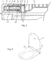
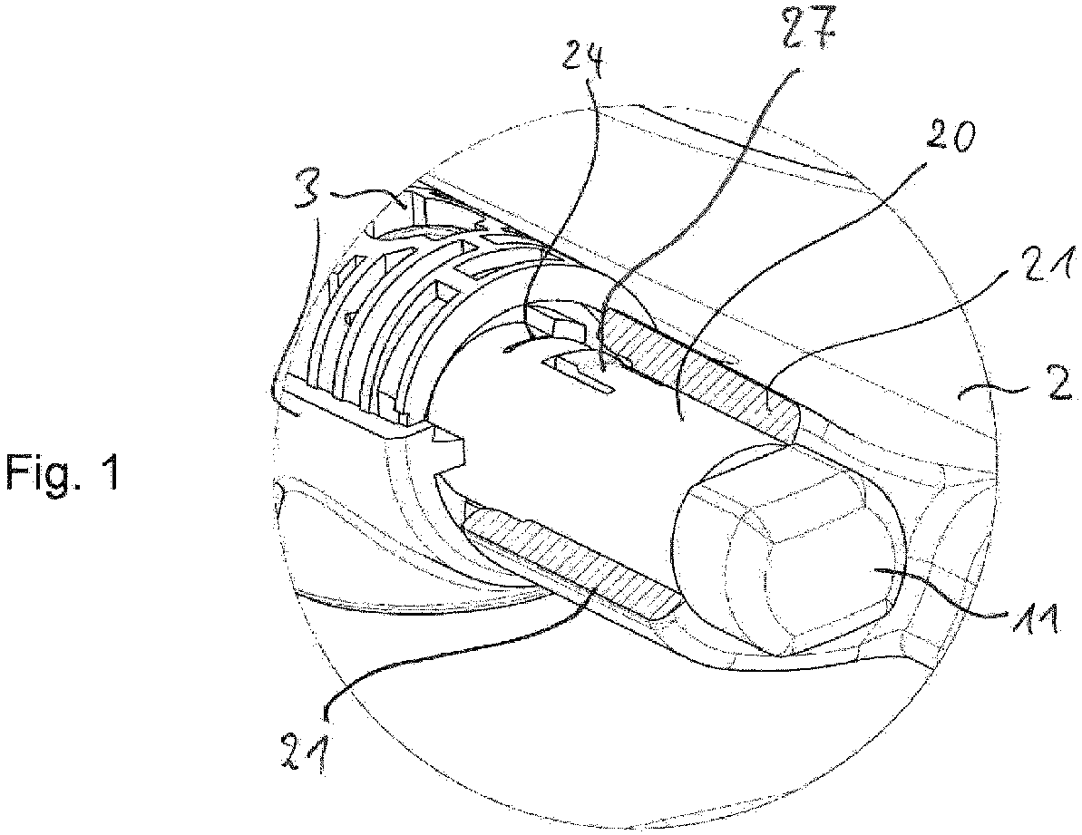
- Fig. 4 represents a toilet (lid) set according to the invention in perspective, with a lid 1 folded up and a seat 2 is folded down. Both are held on a mounting part 3 on a toilet body, not shown, and relatively folds.
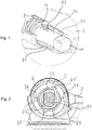
- Fig. 1 shows a fragmentary perspective view from the left rear (with respect to the perspective of Fig. 1 and regarding a perspective with a view of at the front of the WC from diagonally left behind).
- this concerns the left part of the illustration in relation to Fig. 3 from the back left, because there in Fig. 3 the perspective is directed horizontally from the front to the wall.
- the reference numeral 20 denotes an initially substantially cylindrical sleeve of injection-molded plastic, whose in Fig. 1 forward right and in Fig. 3 left-facing part has the shape of a pin 11.
- This sleeve 20 is according to Fig. 1 from a part 21 of the toilet seat 2, which part 21 in Fig. 1 is shown partially cut open, but actually runs closed around the sleeve 20 around.
- This part 21 of the toilet seat 2 is located in Fig. 1 going right to the back in the toilet seat 2, resulting in Fig. 3 corresponds to a continuation up out of the drawing level and in Fig. 2 to the right.
- the part 21 is freely rotatable relative to the sleeve 20 and together with this forms a pivot bearing for a folding movement of the toilet seat 2.
- the journal extension 11 in turn is how Fig. 3 shows, form-fitting in a Fig. 1 not visible toilet cover 1 is held and accordingly rotates with a folding movement of the toilet cover 1 with this.
- This is due to the one-piece design for the entire sleeve 20, the opposite to the pin 11 part (in Fig. 1 left behind) is rotatably received in the mounting part 3.
- This mounting part 3 can be seen in Fig. 3 in longitudinal section, including its attachment via screw 4 in an underlying toilet body (the nuts are not drawn on the external threads of the screw 4).
- the upper cover of the mounting part 3 which explains the illustrated rib structure, in the mounted and complete state according to Fig. 4 is not visible but has reinforcing character.
- Fig. 1 This in Fig. 1 axially rearmost part of the sleeve 20 is located in Fig. 3 (in its left part) on the right and is together with the mounting part 3 and a part of the seat 2 in its environment in Fig. 2 shown cut perpendicular to the axis of rotation. It can be seen that the sleeve in this axially innermost section two arms 23 with each approximately circular arc-shaped contour, through a respective slot 24, one of which in Fig. 1 can be seen, are disconnected from the rest of the sleeve. Since the sleeve is an injection molded part made of a polymer material which has a certain inherent elasticity, an elastic arm 23 is formed in each case through the slot 24.
- each of the arms 23 there is a radially outwardly projecting projection 25, the radially outwardly facing outer surface extends approximately in the circumferential direction and its angled boundary surfaces have different angles of incidence with respect to the respective radial direction with respect to the axis of rotation.
- the pointing in the direction of the respective (remaining) arm surface is chamfered by a few degrees and the opposite and away from the lever surface by a significantly larger angle of about 30 °.
- Each arm 23 covers, including its respective projection 25 an angular portion of about 45 ° from the total circumference.
- the mounting part 3 has a substantially cylindrical inner circumferential surface with two projections 26 which at their radially inwardly facing boundary surface in the circumferential direction and at the two angled side surfaces (as in Fig. 2 Recognizable) again inclined by only a few degrees with respect to the radial direction inclined.
- Fig. 2 illustrates that upon rotation of the sleeve 23, so the coupled via the pin 11 lid 1, from the horizontal and closed position shown in the figures in the vertical, the projections 25 and 26 each approach each other by the projections 25 in Fig. 2 to be turned counterclockwise. In a suitable to be selected and usually lying slightly beyond the vertical position stop position, a contact is formed, so that the rotation stop formed by the projections 25 and 26 comes into effect.
- Fig. 2 also shows within the sleeve 20 an axially inwardly facing and in Fig. 3 also visible pin 27 of the Fig. 3 recognizable rotary damper 10.
- This is a form-fitting in an in Fig. 2 in section U-shaped and axially even further inside then held closed in the upper area receiving the mounting part 3.
- the rotary damper 10 is mounted positively in the mounting part 3 and in particular rotationally fixed, whereby the loads resting on it are transferred to the mounting part 3 and ultimately its ringbefest Trentsmaschine 4. Since the rotary damper 10 functionally has a damped pivot bearing, it accordingly serves as a pivot bearing for the cover 1 (relative to the mounting part 3). Accordingly, the parts 23 to 26 described in connection with the rotation stop are not concerned with a bearing function in the sense of a load bearing.
- Fig. 1 also shows axially slightly outside of the rotation stop described a resilient tongue 27 extending in the axial direction in contrast to the arms 23.
- As in Fig. 1 it is visibly thickened at its distal end and thus prevents withdrawal of the sleeve 20 to the front right from the part 21 of the seat 2, as long as they pass through the inserted from inside the rotary damper 10 (FIG. Fig. 3 ) is prevented from elastically dodging inward. So this is a backup.
- Fig. 3 shows, as already mentioned, the elements of the Fig. 1 and 2 in front view and in a horizontal axis containing the rotation axis (ie with respect to Fig. 4 in a perspective from bottom left diagonally upwards to the right).
- Fig. 3 clarifies that and why the rotary damper 10 in Fig. 1 is not visible and how this blocks the just mentioned tongue 27 from the inside. He is doing rotatably pressed into the sleeve 20, that is non-positively connected thereto. It can also be seen how the already mentioned pin 11 is held in a receptacle 12 of the lid 1 and how on the axially opposite side on the one hand, the sleeve 20 with her (in Fig. 3 on the right) Drehaniliade with the arms 23 and on the other hand, the rotary damper 10 with his in Fig. 2 recognizable pin 27 engages in the mounting part 3.
- opposite side could basically be designed mirror-symmetrical, ie a further rotary damper for the cover 1 and a further rotation stop therefor included.
- a rotary damper for the seat 2 could be provided on the opposite side.
- a rotatable connection between a sleeve (analog 20) and the cover 1 instead of the positive connection with the pin 11 ie a rotationally symmetrical pin in a rotationally symmetrical recording
- a rotationally fixed connection between the seat 2 ie the analog part to 21
- a rotation stop could also be present for the seat, insofar as in Fig. 3 shown for the left side.
Landscapes
- Health & Medical Sciences (AREA)
- Public Health (AREA)
- Toilet Supplies (AREA)
Abstract
einen auf dem WC-Körper montierbaren und darauf hoch- und
herunterklappbaren Teil (1) und
einen Montageteil (3), der zur Montage des klappbaren Teils (1) auf dem WC-Körper ausgelegt ist und den klappbaren Teil (1) drehbeweglich hält,
wobei der klappbare Teil (1) und der Montageteil (3) über ein Drehgelenk (10) verbunden sind,
dadurch gekennzeichnet, dassin einem eine Drehachse des Drehgelenks (10) umgebenden Teil (20) der WC-Garnitur (1-3) ein Drehanschlag (20,23,25,26) zur Begrenzung der Hochklappbewegung des klappbaren Teils (1) vorgesehen ist.
Description
- Die vorliegende Erfindung bezieht sich auf eine WC-Garnitur für ein WC (Wasserklosett).
- WCs weisen regelmäßig einen WC-Körper mit einer WC-Schüssel auf, welcher in vielen Fällen aus Keramik besteht. Bei zum Sitzen vorgesehenen WCs sind darauf in den meisten Fällen klappbare Teile montiert, nämlich WC-Sitze oder WC-Deckel oder beides. Ein WC-Sitz dient dem Benutzer zum Sitzen und ein WC-Deckel zum Verschließen der WC-Schüssel, wobei in der Regel auch ein WC-Sitz mitabgedeckt wird. Der klappbare Teil ist dabei über zumindest ein Montageteil an dem WC-Körper drehbeweglich gehalten.
- Im Folgenden wird die Baueinheit aus einem solchen Montageteil und dem klappbaren Teil, also einem klappbaren WC-Sitz oder einem klappbaren WC-Deckel, als WC-Garnitur bezeichnet, wobei, wie gerade erwähnt, nicht zwingend ein WC-Deckel vorgesehen sein muss und deswegen nicht von einer sogenannten Deckelgarnitur die Rede ist.
- Beim Hochklappen des klappbaren Teils gerät dieses in eine in der Regel etwas jenseits einer vertikalen Position liegende Lage, in der der klappbare Teil gegen eine Wand anliegt, an der oder vor der das WC montiert ist, oder auch gegen ein anderes WC-Teil. So kann, wenn üblicherweise ein WC-Sitz und ein WC-Deckel vorgesehen sind, der WC-Sitz beim Hochklappen an oder in dem bereits hochgeklappten WC-Deckel zur Anlage kommen. Außerdem kann es zu einer Anlage an einem für eine Duscheinrichtung vorgesehenen Aufbau im hinteren (also wandnahen) Teil des WCs kommen, wenn es sich um ein Dusch-WC handelt.
- Der Erfindung liegt die Aufgabe zugrunde, eine WC-Garnitur und ein WC mit einer solchen WC-Garnitur anzugeben, die verbesserte Gebrauchseigenschaften haben.
- Die Aufgabe wird gelöst durch eine WC-Garnitur zur Montage auf einem WC-Körper mit einer WC-Schüssel, welche WC-Garnitur aufweist: einen auf dem WC-Körper montierbaren und darauf hoch- und herunterklappbaren Teil und einen Montageteil, der zur Montage des klappbaren Teils auf dem WC-Körper ausgelegt ist und den klappbaren Teil drehbeweglich hält, wobei der klappbare Teil und der Montageteil über ein Drehgelenk verbunden sind, dadurch gekennzeichnet, dass in einem eine Drehachse des Drehgelenks umgebenden Teil der WC-Garnitur ein Drehanschlag zur Begrenzung der Hochklappbewegung des klappbaren Teils vorgesehen ist, sowie durch ein damit ausgestattetes WC.
- Eine Grundüberlegung des Erfinders war, dass ein Anliegen des klappbaren Teils an einem anderen WC-Teil und insbesondere an einer Wand hinter dem WC zwar üblich ist und bei Bedarf auch eine geeignete Wegbegrenzung zur Verfügung stellt. Allerdings ist nicht auszuschließen, dass eine Kollision bei der Herstellung dieser Anlage zu Spuren an dem klappbaren Teil oder der Wand führt. Besonders gilt dies für einen WC-Deckel, bei dem solche Spuren an seiner im geschlossenen Zustand des WCs sichtbaren Oberseite vorhanden wären, und natürlich für eine (vielleicht mit empfindlicher Oberfläche ausgestattete) Badezimmerwand hinter dem WC.
- Aber auch bei einer Kollision zwischen einem hochklappbaren Garniturteil und einem Duscheinrichtungsgehäuse im hinteren Bereich eines Dusch-WCs oder im Prinzip auch bei einer Kollision zwischen einem gerade hochgeklappten WC-Sitz und einem davor schon hochgeklappten WC-Deckel kann es zu optischen Mängeln oder gar kleinen Beschädigungen kommen. Darüber hinaus kann das Kollisionsgeräusch als unangenehm empfunden werden und vermittelt jedenfalls nicht unbedingt einen Qualitätseindruck.
- Daher ist erfindungsgemäß ein Drehanschlag für die Klappbewegung vorgesehen, wobei dieser Drehanschlag in einem die Drehachse der Klappbewegung umgebenden Teil vorgesehen ist. Der Drehanschlag kann die Positionsbegrenzung für die Hochklappbewegung sicherstellen und damit eine unerwünschte Kollision vermeiden.
- Der Drehanschlag ist dazu in einem Teil der WC-Garnitur vorgesehen, der die Drehachse umgibt. Ein solcher Teil kann z. B. konzentrisch zur Drehachse und im Wesentlichen zylindrisch ausgeführt sein, wobei davon im Fall des Montageteils ein Fuß nach unten oder im Fall eines WC-Sitzes oder WC-Deckels dann die (hinsichtlich der Drehachse) distalen Bereiche sich mehr oder weniger radial erstrecken. Diese Anordnung des Drehanschlags erlaubt eine je nach Wunsch und Bedarf sichtverdeckte, gegen Verschmutzungen geschützte, reinigungsfreundliche, hinsichtlich Verletzungen (Einklemmen) unkritische und/oder in praktischer Weise mit anderen Teilen, etwa des Drehgelenks, integrierte Ausführung. Der Drehanschlag ist also vorzugsweise hinsichtlich Sichtbarkeit, Reinigung und/oder Zugriffsmöglichkeiten verdeckt ausgebildet.
- Er ist dabei so ausgelegt, dass er zur Wirkung kommt, bevor die eigentlich zu verhindernde Anlage hergestellt wird. Bspw. kann der WC-Deckel vor Anschlagen an der Wand durch den Drehanschlag gestoppt werden, womit die zuvor geschilderten Beeinträchtigungen vermieden werden.
- Eine bevorzugte Variante der Erfindung richtet sich auf einen WC-Deckel als klappbaren Teil, also auf eine WC-Deckelgarnitur mit mindestens einem Deckel (und vorzugsweise außerdem einem Sitz). Obwohl grundsätzlich ein Drehanschlag auch für einen klappbaren Sitz sinnvoll und vorteilhaft ist, ist die beschriebene Kollision im Fall eines WC-Deckels in der Regel nachteiliger. Es ist dann eine gut sichtbare Oberfläche (auch bei geschlossenem WC) des Deckels betroffen und ferner ein anderer WC-Teil, etwa ein Duscheinrichtungsgehäuse, oder eben die erwähnte Wand hinter dem WC.
- Es ist grundsätzlich bekannt, die hier in Bezug genommene Klappbewegung eines WC-Sitzes oder WC-Deckels zu dämpfen. Geeignete Dämpfer können eine annähernd zylindrische und zur Drehachse symmetrische Form haben und in ähnlicher Weise in einem die Drehachse umgebenden Teil des klappbaren Teils oder des Montageteils verbaut sein wie der Drehanschlag. Über einen Drehdämpfer kann die Klappbewegung zusätzlich gedämpft werden, so dass die Kollision mit dem Drehanschlag etwas gebremst erfolgt. Im gleichen Sinn wurden im Stand der Technik Drehdämpfer bereits vorgesehen, um ein zu hartes Anschlagen z. B. eines WC-Deckels an einer Wand zu vermeiden, konnten dies aber nicht wirklich verhindern, vor allem wenn z. B. Kinder etwas ungestüm mit einem WC umgingen.
- Es kann aber auch ein Drehdämpfer nur zum Dämpfen der Absenkbewegung des klappbaren Teils vorgesehen sein, jedenfalls in der Nähe des erfindungsgemäßen Drehanschlags (und möglicherweise ein weiterer Drehdämpfer an einer anderen Stelle).
- Eine besonders günstige Ausgestaltung sieht in Kombination mit einem Drehdämpfer eine hülsenartige Ausgestaltung eines der beiden Drehlagerteile vor, die zum Drehanschlag gehören. Zur Veranschaulichung wird auf das Ausführungsbeispiel verwiesen.
- Eine weitere bevorzugte Ausgestaltung sieht dabei vor, dass ein Teil des Drehanschlags, insbesondere die Hülse aus einem Drehgelenkteil gebildet ist, also aus einem der Teile, die die klappbare Halterung des oder eines weiteren klappbaren Garniturteils bewirken und gegeneinander drehend laufen. Solche Drehgelenkteile können dann z. B. durch Einführung geeigneter Vorsprünge gleichzeitig (also einstückig) als Drehanschlag ausgebildet werden. Dies gewährleistet eine besonders einfache und ökonomische Realisierung der Erfindung. Im Ausführungsbeispiel gilt das konkret für einen Teil des Drehgelenks eines weiteren klappbaren Teils, nämlich eines Sitzes bei auf einen Deckel einwirkendem Drehanschlag.
- Vorzugsweise ist der Drehanschlag mehrfach, insbesondere doppelt, vorhanden. Zum einen kann dies den Vorteil einer Verteilung der auftretenden Kräfte haben. Die erfindungsgemäße Unterbringung des Drehdämpfers relativ nah bei der Drehachse hat ja unvermeidlicherweise relativ kurze Hebelarme zur Folge, weswegen dieser Aspekt vor allem bei einer preisgünstigen Ausgestaltung in Kunststoff (z. B. Spritzguss) relevant sein kann. Außerdem oder alternativ kann der Vorteil im Vordergrund stehen, eine rotationssymmetrische Gestaltung zu erzielen, die beim Einbau z. B. bei einer zweizähligen Symmetrie ein Vertauschen von "oben" und "unten" oder von "links" und "rechts" zulässt.
- Die Wiederholung des Drehanschlags kann entlang einem Umlauf um die Drehachse der Klappbewegung geschehen, so dass z. B. bei einer zweizähligen Symmetrie ein Drehanschlag an entgegengesetzter Position zum anderen (bezüglich dieses Umlaufs) liegt.
- Eine weitere bevorzugte Ausgestaltung der Erfindung, die hier vorsorglich auch unabhängig von der konkreten Anordnung im die Drehachse umgebenden Teil des klappbaren Teils oder des Montageteils entsprechend Anspruch 1, aber optional in Verbindung mit allen anderen Merkmalen der Offenbarung, dargestellt wird, betrifft einen Überschnappmechanismus. Das bedeutet, dass ein Teil des Drehanschlags, also eines der aneinander anschlagenden Elemente, bei einer kräftemäßigen Überlastung elastisch ausweichen und damit eine Zerstörung des Drehanschlags verhindern kann. Wenn z. B. in einem Familienhaushalt der Drehanschlag von Vorteil ist, weil mit einer etwas ungestümen Handhabung von WC-Deckeln (oder Sitzen) durch Kinder zu rechnen ist, kann das auch bedeuten, dass diese aus Übermut oder Unwissen z. B. den WC-Deckel über die durch den Drehanschlag definierte Endposition hinaus drücken. In diesem Fall soll also der Überschnappmechanismus einen Schaden am Drehanschlag und möglicherweise Drehlager verhindern. Da es in vielen Fällen dann nur noch eine kurze Bewegungsstrecke bis zu einer anderweitigen Begrenzung geben wird, etwa bis zur Anlage an der Wand, sind gleichzeitig größere Schäden am WC-Deckel oder WC-Sitz nicht zwingend zu erwarten.
- In diesem Sinn kann eines der Anschlagelemente elastisch gehalten sein und infolge dieser elastischen Halterung ausweichen, etwa durch einen elastischen Arm, der in einem drehachsensenkrechten Schnitt ungefähr in Umfangsrichtung verläuft und dabei einen Teilumfang abdeckt (vgl. Ausführungsbeispiel). An einem distalen Ende eines solchen elastischen Arms (distal bezüglich des Übergangs des Arms zu dem Teil, zu dem er gehört) kann dann z. B. ein im Wesentlichen radial nach außen oder innen ragender Vorsprung vorgesehen sein. Ein solcher Arm kann z. B. günstig in der bereits erwähnten Hülse realisiert sein.
- Die Überschnappfunktion lässt sich dabei fördern, indem eine der unmittelbar in Anlage miteinander kommenden Anschlagflächen des Drehanschlags eine entsprechende schräge Orientierung zu der Richtung dieses Kontakts aufweist und damit nach dem Prinzip der schiefen Ebene eine entsprechende elastische Kraft aufbringen kann.
- Da der beschriebene Überschnappmechanismus zerstörungsfrei funktionieren soll, ist vorzugsweise eine Rückschnappmöglichkeit vorgesehen. Mit dieser kann nach einem Überschnappen wieder der ursprüngliche Funktionszustand hergestellt werden, können also z. B. Anschlagelemente wieder aneinander entlang bewegt werden, um in die den eigentlichen Drehanschlag bewirkende Relativposition zueinander zu gelangen. Dazu kann ebenfalls eine schräge Fläche an geeigneten Anschlagflächen vorgesehen sein, wobei diese Anschlagfläche eine deutlich andere Neigung als die zuvor erwähnte aufweisen kann, sodass für das Rückschnappen kleinere Kräfte genügen. Zur Erläuterung wird auf das Ausführungsbeispiel verwiesen.
- Die Erfindung betrifft ferner auch ein komplettes WC mit einem klappbaren Teil und einer diesen Teil entsprechend drehbeweglich haltenden Halteeinrichtung. Wenn das WC über eine WC-Garnitur gemäß der bisherigen Erläuterung der Erfindung verfügt, entspricht die Halteeinrichtung dem Montageteil. Es sind aber auch Fälle denkbar, bei denen die Halteeinrichtung einstückig in dem WC-Körper realisiert ist und damit nicht getrennt vom WC-Körper existiert und die ebenfalls mit erfasst sein sollen. Analog gilt das für WCs, bei denen eine solche Halteeinrichtung Teil eines anderweitigen Aufbaus, etwa eines Duscheinrichtungsaufbaus, ist und dementsprechend einstückiger Bestandteil eines Elements ist, das seinerseits vorrangig anderen Aufgaben als der Halterung des klappbaren WC-Deckels oder -Sitzes dient.
- Die Erfindung wird im Folgenden anhand eines konkreten Ausführungsbeispiels näher erläutert, das in den Figuren näher dargestellt ist. Dabei zeigt:
- Fig.1
- eine perspektivische und teils aufgeschnittene Ausschnittdarstellung einer erfindungsgemäßen WC-Garnitur mit einem Drehanschlag;
- Fig. 2
- eine zur Drehachse senkrechte Schnittdarstellung im linken Bereich der perspektivischen Darstellung aus
Fig. 1 und, bezogen aufFig. 1 , in der Blickrichtung nach schräg links hinten; - Fig. 3
- eine längs der in der Figur quer liegenden Drehachse laufende Schnittdarstellung, die etwa die Hälfte der erfindungsgemäßen WC-Garnitur auf einem WC-Körper zeigt;
- Fig. 4
- zeigt in perspektivischer Darstellung und als Übersicht die WC-Garnitur aus den
Figuren 1 bis 3 . - Zunächst wird zur Veranschaulichung der Grundstruktur auf
Fig. 4 verwiesen, die eine erfindungsgemäße WC-(Deckel-)Garnitur perspektivisch darstellt, wobei ein Deckel 1 hochgeklappt und ein Sitz 2 heruntergeklappt ist. Beide sind über ein Montageteil 3 auf einem nicht näher dargestellten WC-Körper gehalten und relativ dazu klappbar. -
Fig. 1 zeigt eine ausschnittsweise perspektivische Darstellung von links hinten (in Bezug auf die Perspektive derFig. 1 und bezüglich einer Perspektive mit Blick von vorn auf das WC von schräg links hinten). In Bezug aufFig. 3 betrifft das dort den linken Teil der Darstellung, und zwar in Bezug aufFig. 3 von hinten links, weil dort inFig. 3 die Perspektive horizontal von vorn auf die Wand gerichtet ist. - Das Bezugszeichen 20 bezeichnet dabei eine zunächst im Wesentlichen zylindrische Hülse aus spritzgegossenem Kunststoff, deren in
Fig. 1 nach vorn rechts und inFig. 3 nach links weisender Teil die Form eines Zapfens 11 hat. Diese Hülse 20 ist gemäßFig. 1 von einem Teil 21 des WC-Sitzes 2 umfasst, welcher Teil 21 inFig. 1 zum Teil aufgeschnitten dargestellt ist, tatsächlich aber geschlossen um die Hülse 20 herum läuft. Dieser Teil 21 des WC-Sitzes 2 setzt sich inFig. 1 nach rechts hinten in den WC-Sitz 2 fort, was inFig. 3 einer Fortsetzung nach oben aus der Zeichenebene heraus entspricht und inFig. 2 nach rechts. Der Teil 21 ist gegenüber der Hülse 20 frei drehbar und bildet mit dieser zusammen ein Drehlager für eine Klappbewegung des WC-Sitzes 2. - Der Zapfenfortsatz 11 wiederum ist, wie
Fig. 3 zeigt, formschlüssig in einem inFig. 1 nicht sichtbaren WC-Deckel 1 gehalten und dreht sich dementsprechend bei einer Klappbewegung des WC-Deckels 1 mit diesem mit. Das gilt infolge der einstückigen Ausbildung für die gesamte Hülse 20, deren zu dem Zapfen 11 entgegengesetzter Teil (inFig. 1 links hinten) in dem Montageteil 3 drehbar aufgenommen ist. Diesen Montageteil 3 erkennt man inFig. 3 im Längsschnitt einschließlich seiner Befestigung über Schraubelemente 4 in einem darunterliegenden WC-Körper (wobei die Muttern auf den Außengewinden der Schraubelemente 4 nicht gezeichnet sind). In denFiguren 1 - 3 ist dabei eine für die Funktion dieser Erfindung nicht wesentliche obere Abdeckung des Montageteils 3 weggelassen, was die dargestellte Rippenstruktur erklärt, die im montierten und vollständigen Zustand gemäßFig. 4 nicht sichtbar ist, sondern Verstärkungscharakter hat. - Dieser in
Fig. 1 axial hinterste Teil der Hülse 20 liegt inFig. 3 (in deren linkem Teil) rechts und ist zusammen mit dem Montageteil 3 und einem Teil des Sitzes 2 in seiner Umgebung inFig. 2 senkrecht zur Drehachse geschnitten dargestellt. Dabei erkennt man, dass die Hülse in diesem axial innersten Abschnitt zwei Arme 23 mit jeweils ungefähr kreisbogenförmiger Kontur aufweist, die durch einen jeweiligen Schlitz 24, von denen einer inFig. 1 zu sehen ist, von der übrigen Hülse abgekoppelt sind. Da die Hülse ein Spritzgussteil aus einem Polymermaterial ist, das eine gewisse Eigenelastizität aufweist, ist durch den Schlitz 24 jeweils ein elastischer Arm 23 gebildet. - An dem jeweils distalen Ende jedes der Arme 23 befindet sich ein radial nach außen vorstehender Vorsprung 25, dessen radial nach außen weisende Außenfläche ungefähr in Umfangsrichtung verläuft und dessen dazu gewinkelte Begrenzungsflächen unterschiedliche Anstellungswinkel bezüglich der jeweiligen radialen Richtung bezogen auf die Drehachse haben. Die in Richtung des jeweiligen (restlichen) Armes zeigende Fläche ist um wenige Grad angeschrägt und die entgegengesetzte und von dem Hebel weg weisende Fläche um einen deutlich größeren Winkel von etwa 30°. Jeder Arm 23 deckt einschließlich seines jeweiligen Vorsprungs 25 einen Winkelteil von etwa 45° am Gesamtumfang ab.
- Andererseits weist der Montageteil 3 eine im Wesentlichen zylindrische Innenmantelfläche mit zwei Vorsprüngen 26 auf, die an ihrer radial nach innen weisenden Begrenzungsfläche in Umfangsrichtung und an den beiden dazu gewinkelten Seitenflächen (wie in
Fig. 2 erkennbar) erneut um nur wenige Grad gegenüber der radialen Richtung geneigt verlaufen.Fig. 2 veranschaulicht, dass bei einer Drehung der Hülse 23, also des über den Zapfen 11 gekoppelten Deckels 1, aus der in den Figuren dargestellten horizontalen und geschlossenen Position in die Vertikale sich die Vorsprünge 25 und 26 jeweils einander annähern, indem die Vorsprünge 25 inFig. 2 gegen die Uhrzeigerrichtung verdreht werden. Bei einer geeignet zu wählenden und im Regelfall etwas jenseits der vertikalen Position liegenden Anschlagsposition entsteht ein Kontakt, sodass der aus den Vorsprüngen 25 und 26 gebildete Drehanschlag zur Wirkung kommt. - Wenn nun der Deckel 1 aus irgendwelchen Gründen über diese Position mit einer relativ großen Kraft hinaus bewegt wird, sorgen die erwähnten kleinen Anstellwinkel in den seitlichen Begrenzungsflächen der Vorsprünge 25 und 26, die miteinander in Anlage (und dabei parallel zueinander) stehen, nach dem Prinzip einer schiefen Ebene dafür, dass der jeweilige Vorsprung 25 und mit ihm der jeweilige Hebel 23 elastisch nach innen gedrückt wird, sodass der Drehanschlag schließlich durch eine elastische Verformung des axial innersten Teils der Hülse 20 überwunden werden kann.
- Umgekehrt können infolge der deutlich schrägeren Ausbildung der entgegengesetzten Seitenfläche des jeweiligen Vorsprungs 25 die Vorsprünge 25 einer Rückführung mit geringerem Kraftaufwand unter den Vorsprüngen 26 "hindurchtauchen", um wieder in den regulären Bereich zurückzukehren.
-
Fig. 2 zeigt darüber hinaus innerhalb der Hülse 20 einen axial nach innen weisenden und inFig. 3 ebenfalls sichtbaren Zapfen 27 des inFig. 3 erkennbaren Drehdämpfers 10. Dieser ist formschlüssig in einer inFig. 2 im Schnitt U-förmigen und axial noch weiter innen liegend dann auch im oberen Bereich geschlossenen Aufnahme des Montageteils 3 gehalten. Damit ist der Drehdämpfer 10 im Montageteil 3 formschlüssig und insbesondere drehfest gelagert, womit die auf ihm ruhenden Lasten auf das Montageteil 3 und letztlich dessen Schraubbefestigungsteile 4 übertragen werden. Da der Drehdämpfer 10 in sich funktionsgemäß ein gedämpftes Drehlager aufweist, dient er dementsprechend als Drehlager für den Deckel 1 (gegenüber dem Montageteil 3). Dementsprechend geht es bei den in Zusammenhang mit dem Drehanschlag beschriebenen Teilen 23 bis 26 nicht um eine Lagerfunktion im Sinn einer Lastaufnahme. -
Fig. 1 zeigt ferner axial etwas außerhalb des beschriebenen Drehanschlags eine im Unterschied zu den Armen 23 in axialer Richtung verlaufende federnde Zunge 27. Diese hat für die Erfindung keine wesentliche Bedeutung und wird deswegen nur kurz erläutert. Wie inFig. 1 sichtbar ist sie an ihrem distalen Ende etwas verdickt und verhindert damit ein Herausziehen der Hülse 20 nach vorn rechts aus dem Teil 21 des Sitzes 2, solange sie durch den von innen eingesteckten Drehdämpfer 10 (Fig. 3 ) daran gehindert ist, elastisch nach innen auszuweichen. Es handelt sich also um eine Sicherung. -
Fig. 3 zeigt, wie bereits erwähnt, die Elemente derFig. 1 und 2 in Frontansicht und in einem die Drehachse horizontal enthaltenden Schnitt (also bezüglichFig. 4 in einer Perspektive von unten links schräg nach oben rechts).Fig. 3 verdeutlicht, dass und warum der Drehdämpfer 10 inFig. 1 nicht sichtbar ist und wie dieser die gerade erwähnte Zunge 27 von innen blockiert. Er ist dabei drehfest in die Hülse 20 eingepresst, also kraftschlüssig mit dieser verbunden. Man erkennt auch, wie der bereits erwähnte Zapfen 11 in einer Aufnahme 12 des Deckels 1 gehalten ist und wie auf der axial entgegengesetzten Seite einerseits die Hülse 20 mit ihrem (inFig. 3 rechts liegenden) Drehanschlagende mit den Armen 23 und andererseits der Drehdämpfer 10 mit seinem inFig. 2 erkennbaren Zapfen 27 in den Montageteil 3 hineingreift. - Die in
Fig. 3 nicht dargestellte entgegengesetzte Seite könnte grundsätzlich spiegelsymmetrisch gestaltet sein, also einen weiteren Drehdämpfer für den Deckel 1 und einen weiteren Drehanschlag dafür enthalten. Alternativ könnte auf der entgegengesetzten Seite ein Drehdämpfer für den Sitz 2 vorgesehen sein. Dazu könnte eine drehbare Verbindung zwischen einer Hülse (analog 20) und dem Deckel 1 anstelle der formschlüssigen Verbindung mit dem Zapfen 11 (also ein rotationssymmetrischer Zapfen in einer rotationssymmetrischen Aufnahme) vorgesehen sein und ferner eine drehfeste Verbindung zwischen dem Sitz 2 (also dem analogen Teil zu 21) und einer Hülse (analog 20). Dann könnte insbesondere ein Drehanschlag auch für den Sitz vorhanden sein, insoweit wie inFig. 3 für die linke Seite gezeigt. - In einer parallelen Anmeldung derselben Anmelderin ist eine Variante dargestellt, in der auf der entgegengesetzten Seite zwar ein weiterer Drehdämpfer für den Sitz 2, aber ohne Drehanschlag vorgesehen ist, und ferner ein Mechanismus für eine Trennbarkeit von Sitz 2 und Deckel 1 und schließlich Montageteil 3 voneinander. Dies wird hier nicht näher erläutert.
Claims (15)
- WC-Garnitur (1-3) zur Montage auf einem WC-Körper mit einer WC-Schüssel, welche WC-Garnitur (1-3) aufweist:einen auf dem WC-Körper montierbaren und darauf hoch- und herunterklappbaren Teil (1) undeinen Montageteil (3), der zur Montage des klappbaren Teils (1) auf dem WC-Körper ausgelegt ist und den klappbaren Teil (1) drehbeweglich hält,wobei der klappbare Teil (1) und der Montageteil (3) über ein Drehgelenk (10) verbunden sind,dadurch gekennzeichnet, dass in einem eine Drehachse des Drehgelenks (10) umgebenden Teil (20) der WC-Garnitur (1-3) ein Drehanschlag (20,23,25,26) zur Begrenzung der Hochklappbewegung des klappbaren Teils (1) vorgesehen ist.
- WC-Garnitur (1-3) nach Anspruch 1, bei der der klappbare Teil (1) ein Deckel zum Abdecken der WC-Schüssel und die WC-Garnitur (1-3) eine WC-Deckelgarnitur ist, optional mit einem zusätzlichen Sitz (2) für einen Benutzer, welcher Sitz (2) ebenfalls im montierten Zustand auf dem WC-Körper hoch- und herunterklappbar gehalten ist.
- WC-Garnitur (1-3) nach Anspruch 1 oder 2, bei der der Drehanschlag (20,23,25,26) gebildet ist zwischen einem sich mit dem klappbaren Teil (1) drehenden Teil (20) und einem bzgl. der Klappbewegung zu dem Montageteil (3) festen Teil.
- WC-Garnitur (1-3) nach Anspruch 3, bei der einer der beiden Teile (20,26) den Drehdämpfer (10) als Hülse (20) umfasst.
- WC-Garnitur (1-3) nach einem der vorstehenden Ansprüche, bei der ein Teil (20) des Drehanschlags (20,23,25,26), vorzugsweise die Hülse (20) nach Anspruch 4, ein Teil eines Drehgelenks (20,21) des klappbaren Teils oder eines weiteren klappbaren Teils (2) der WC-Garnitur (1-3) ist.
- WC-Garnitur (1-3) nach einem der vorstehenden Ansprüche, bei dem der Drehanschlag (20,23,25,26) mehrfach, insbesondere doppelt, vorgesehen ist, und zwar entlang einem Umlauf um die Drehachse der Klappbewegung mehrfach, wobei jeweils ein Anschlagelement (25) jedes Drehanschlags an einem sich mit dem klappbaren Teil (1) drehenden Teil (20) vorgesehen ist und jeweils ein Anschlagelement (26) jedes Drehanschlags an einem bzgl. der Klappbewegung zu dem Montageteil (3) festen Teil.
- WC-Garnitur (1-3) nach Anspruch 6, bei der die Mehrzahl Drehanschläge (20,23,25,26) bzgl. der Drehachse der Klappbewegung rotationssymmetrisch ist.
- WC-Garnitur (1-3) nach einem der vorstehenden Ansprüche, bei der der zumindest eine Drehanschlag (20,23,25,26) überschnappend ausgestaltet ist, also zumindest eines der anschlagenden Elemente (25,26) des Drehanschlags (20,23,25,26) bei Überlastung elastisch ausweicht und damit eine Zerstörung verhindert.
- WC-Garnitur (1-3) nach Anspruch 8, bei der ein Anschlagelement (25) des Drehanschlags (20,23,25,26) elastisch gehalten ist und infolge der elastischen Halterung überschnappend ausweichen kann.
- WC-Garnitur (1-3) nach Anspruch 9, bei der das Anschlagelement (25) an einem elastischen Arm (23) gehalten ist, welcher Arm (23) in einem Schnitt senkrecht zur Drehachse der Klappbewegung in Umfangsrichtung verläuft und einen Teilumfang abdeckt.
- WC-Garnitur (1-3) nach einem der Ansprüche 9 oder 10, bei dem eines der Anschlagelemente (25,26) eine relativ zu einer lokalen Richtung des Anschlags an diesem Anschlagelement (25) schräge Anschlagfläche zur Erleichterung des elastischen Ausweichens aufweist.
- WC-Garnitur (1-3) nach Anspruch 4 in Verbindung mit Anspruch 10 und optional auch 11, bei der der Federarm (23) Teil der den Drehdämpfer (10) umgreifenden Hülse (20) ist.
- WC-Garnitur (1-3) nach einem der Ansprüche 8 bis 12, bei der der Drehanschlag (20,23,25,26) so ausgestaltet ist, dass er aus einer übergeschnappten Situation durch Rückführung wieder in seinen ursprünglichen Funktionszustand gebracht werden kann, insbesondere indem an einem Anschlagelement (25) eine relativ zu einer lokalen Richtung eines Anschlags bei der Rückführung schräge Anschlagfläche zur Erleichterung eines elastischen Ausweichens bei der Rückführung vorgesehen ist.
- WC mit einem WC-Körper, der eine WC-Schüssel aufweist, und
einem auf dem WC-Körper montierten und hoch- und herunterklappbaren Teil (1) sowie einer Halteeinrichtung (3), die den klappbaren Teil (1) drehbeweglich hält,
wobei der klappbare Teil (1) und die Halteeinrichtung (3) über ein Drehgelenk (10) verbunden sind,
dadurch gekennzeichnet, dass in einem eine Drehachse des Drehgelenks (10) umgebenden Teil (20) der WC-Garnitur ein Drehanschlag (20,23,25,26) zur Begrenzung der Hochklappbewegung des klappbaren Teils vorgesehen ist. - WC nach Anspruch 14, das aus dem WC-Körper und einer WC-Garnitur (1-3) nach einem der Ansprüche 1 bis 13 besteht, wobei die Halteeinrichtung (3) der Montageteil (3) ist.
Priority Applications (2)
| Application Number | Priority Date | Filing Date | Title |
|---|---|---|---|
| PL18153799T PL3517007T3 (pl) | 2018-01-29 | 2018-01-29 | Zestaw WC z częścią składaną |
| EP18153799.4A EP3517007B1 (de) | 2018-01-29 | 2018-01-29 | Wc-garnitur mit klappbarem teil |
Applications Claiming Priority (1)
| Application Number | Priority Date | Filing Date | Title |
|---|---|---|---|
| EP18153799.4A EP3517007B1 (de) | 2018-01-29 | 2018-01-29 | Wc-garnitur mit klappbarem teil |
Publications (2)
| Publication Number | Publication Date |
|---|---|
| EP3517007A1 true EP3517007A1 (de) | 2019-07-31 |
| EP3517007B1 EP3517007B1 (de) | 2020-01-22 |
Family
ID=61074360
Family Applications (1)
| Application Number | Title | Priority Date | Filing Date |
|---|---|---|---|
| EP18153799.4A Active EP3517007B1 (de) | 2018-01-29 | 2018-01-29 | Wc-garnitur mit klappbarem teil |
Country Status (2)
| Country | Link |
|---|---|
| EP (1) | EP3517007B1 (de) |
| PL (1) | PL3517007T3 (de) |
Citations (2)
| Publication number | Priority date | Publication date | Assignee | Title |
|---|---|---|---|---|
| JP2014066261A (ja) * | 2012-09-24 | 2014-04-17 | Nidec Sankyo Corp | ダンパー装置 |
| JP2015194230A (ja) * | 2014-03-31 | 2015-11-05 | 日本電産サンキョー株式会社 | 流体ダンパ装置およびダンパ付き機器 |
-
2018
- 2018-01-29 EP EP18153799.4A patent/EP3517007B1/de active Active
- 2018-01-29 PL PL18153799T patent/PL3517007T3/pl unknown
Patent Citations (2)
| Publication number | Priority date | Publication date | Assignee | Title |
|---|---|---|---|---|
| JP2014066261A (ja) * | 2012-09-24 | 2014-04-17 | Nidec Sankyo Corp | ダンパー装置 |
| JP2015194230A (ja) * | 2014-03-31 | 2015-11-05 | 日本電産サンキョー株式会社 | 流体ダンパ装置およびダンパ付き機器 |
Also Published As
| Publication number | Publication date |
|---|---|
| EP3517007B1 (de) | 2020-01-22 |
| PL3517007T3 (pl) | 2020-06-29 |
Similar Documents
| Publication | Publication Date | Title |
|---|---|---|
| DE102018221112B4 (de) | Lastkraftwagen | |
| DE10329959A1 (de) | Halter für einen Getränkebehälter | |
| EP2679127B1 (de) | WC-Bauteile und WC mit lösbarem Scharnier | |
| DE29912821U1 (de) | Vorrichtung zur Versorgung von Tieren mit Futter | |
| DE2263706C2 (de) | Klappstuhl | |
| DE4201069A1 (de) | Tuer mit einem fallen- und/oder riegelschloss und handhabenbeschlag dafuer | |
| DE102013221616B4 (de) | Betätigungseinheit zum Auslösen eines Spülvorgangs in einem Spülkasten eines WCs | |
| DE102013112570A1 (de) | Vorrichtung zum Betätigen eines in einem Schaltschrank befindlichen Schaltgeräts | |
| WO2016001371A1 (de) | Montagevorrichtung | |
| EP3851004B1 (de) | Montageeinrichtung zur lösbaren montage eines garniturteils auf einem wc-körper | |
| EP3517007B1 (de) | Wc-garnitur mit klappbarem teil | |
| EP1279363B1 (de) | Vorrichtung zur Befestigung eines Bürstenkörpers am Gehäuse einer Bodenreinigungsmaschine | |
| DE202018000438U1 (de) | WC-Garnitur mit klappbarem Teil | |
| EP2149644B1 (de) | Ablaufventil für einen Spülkasten | |
| DE202014105332U1 (de) | Haltevorrichtung für ein Kauspielzeug | |
| DE102007010930B4 (de) | Dämpfungseinrichtung | |
| EP3018280B1 (de) | Türantrieb | |
| DE102011012171B4 (de) | Schlitten für ein zentral in einem Kanal zu führendes Kanalreinigungsgerät | |
| DE202008013833U1 (de) | Toilettensitz | |
| EP1552778B1 (de) | Uriniervorrichtung zur Anbringung an einer eine Toilettenbrille und/oder einen Toilettendeckel aufweisenden Toilettenschlüssel | |
| EP4588414A1 (de) | Montageeinrichtung für wc-garniturteil | |
| DE202024100216U1 (de) | Montageeinrichtung für WC-Garniturteil | |
| DE4428144C2 (de) | Stuhl | |
| DE202020100273U1 (de) | Montageeinrichtung zur lösbaren Montage eines Garniturteils auf einem WC-Körper | |
| AT165238B (de) |
Legal Events
| Date | Code | Title | Description |
|---|---|---|---|
| PUAI | Public reference made under article 153(3) epc to a published international application that has entered the european phase |
Free format text: ORIGINAL CODE: 0009012 |
|
| STAA | Information on the status of an ep patent application or granted ep patent |
Free format text: STATUS: REQUEST FOR EXAMINATION WAS MADE |
|
| 17P | Request for examination filed |
Effective date: 20180816 |
|
| AK | Designated contracting states |
Kind code of ref document: A1 Designated state(s): AL AT BE BG CH CY CZ DE DK EE ES FI FR GB GR HR HU IE IS IT LI LT LU LV MC MK MT NL NO PL PT RO RS SE SI SK SM TR |
|
| AX | Request for extension of the european patent |
Extension state: BA ME |
|
| GRAP | Despatch of communication of intention to grant a patent |
Free format text: ORIGINAL CODE: EPIDOSNIGR1 |
|
| STAA | Information on the status of an ep patent application or granted ep patent |
Free format text: STATUS: GRANT OF PATENT IS INTENDED |
|
| INTG | Intention to grant announced |
Effective date: 20190918 |
|
| GRAS | Grant fee paid |
Free format text: ORIGINAL CODE: EPIDOSNIGR3 |
|
| GRAA | (expected) grant |
Free format text: ORIGINAL CODE: 0009210 |
|
| STAA | Information on the status of an ep patent application or granted ep patent |
Free format text: STATUS: THE PATENT HAS BEEN GRANTED |
|
| RBV | Designated contracting states (corrected) |
Designated state(s): AL AT BE BG CH CY CZ DE DK EE ES FI FR GB GR HR HU IE IS IT LI LT LU LV MC MK MT NL NO PL PT RO RS SE SI SK SM TR |
|
| AK | Designated contracting states |
Kind code of ref document: B1 Designated state(s): AL AT BE BG CH CY CZ DE DK EE ES FI FR GB GR HR HU IE IS IT LI LT LU LV MC MK MT NL NO PL PT RO RS SE SI SK SM TR |
|
| REG | Reference to a national code |
Ref country code: GB Ref legal event code: FG4D Free format text: NOT ENGLISH |
|
| REG | Reference to a national code |
Ref country code: CH Ref legal event code: EP |
|
| REG | Reference to a national code |
Ref country code: CH Ref legal event code: NV Representative=s name: TR-IP CONSULTING LLC, CH |
|
| REG | Reference to a national code |
Ref country code: AT Ref legal event code: REF Ref document number: 1226382 Country of ref document: AT Kind code of ref document: T Effective date: 20200215 |
|
| REG | Reference to a national code |
Ref country code: IE Ref legal event code: FG4D Free format text: LANGUAGE OF EP DOCUMENT: GERMAN |
|
| REG | Reference to a national code |
Ref country code: DE Ref legal event code: R096 Ref document number: 502018000636 Country of ref document: DE |
|
| REG | Reference to a national code |
Ref country code: NL Ref legal event code: MP Effective date: 20200122 |
|
| REG | Reference to a national code |
Ref country code: LT Ref legal event code: MG4D |
|
| PG25 | Lapsed in a contracting state [announced via postgrant information from national office to epo] |
Ref country code: FI Free format text: LAPSE BECAUSE OF FAILURE TO SUBMIT A TRANSLATION OF THE DESCRIPTION OR TO PAY THE FEE WITHIN THE PRESCRIBED TIME-LIMIT Effective date: 20200122 Ref country code: RS Free format text: LAPSE BECAUSE OF FAILURE TO SUBMIT A TRANSLATION OF THE DESCRIPTION OR TO PAY THE FEE WITHIN THE PRESCRIBED TIME-LIMIT Effective date: 20200122 Ref country code: NO Free format text: LAPSE BECAUSE OF FAILURE TO SUBMIT A TRANSLATION OF THE DESCRIPTION OR TO PAY THE FEE WITHIN THE PRESCRIBED TIME-LIMIT Effective date: 20200422 Ref country code: PT Free format text: LAPSE BECAUSE OF FAILURE TO SUBMIT A TRANSLATION OF THE DESCRIPTION OR TO PAY THE FEE WITHIN THE PRESCRIBED TIME-LIMIT Effective date: 20200614 Ref country code: NL Free format text: LAPSE BECAUSE OF FAILURE TO SUBMIT A TRANSLATION OF THE DESCRIPTION OR TO PAY THE FEE WITHIN THE PRESCRIBED TIME-LIMIT Effective date: 20200122 |
|
| PG25 | Lapsed in a contracting state [announced via postgrant information from national office to epo] |
Ref country code: GR Free format text: LAPSE BECAUSE OF FAILURE TO SUBMIT A TRANSLATION OF THE DESCRIPTION OR TO PAY THE FEE WITHIN THE PRESCRIBED TIME-LIMIT Effective date: 20200423 Ref country code: BG Free format text: LAPSE BECAUSE OF FAILURE TO SUBMIT A TRANSLATION OF THE DESCRIPTION OR TO PAY THE FEE WITHIN THE PRESCRIBED TIME-LIMIT Effective date: 20200422 Ref country code: HR Free format text: LAPSE BECAUSE OF FAILURE TO SUBMIT A TRANSLATION OF THE DESCRIPTION OR TO PAY THE FEE WITHIN THE PRESCRIBED TIME-LIMIT Effective date: 20200122 Ref country code: SE Free format text: LAPSE BECAUSE OF FAILURE TO SUBMIT A TRANSLATION OF THE DESCRIPTION OR TO PAY THE FEE WITHIN THE PRESCRIBED TIME-LIMIT Effective date: 20200122 Ref country code: LV Free format text: LAPSE BECAUSE OF FAILURE TO SUBMIT A TRANSLATION OF THE DESCRIPTION OR TO PAY THE FEE WITHIN THE PRESCRIBED TIME-LIMIT Effective date: 20200122 Ref country code: IS Free format text: LAPSE BECAUSE OF FAILURE TO SUBMIT A TRANSLATION OF THE DESCRIPTION OR TO PAY THE FEE WITHIN THE PRESCRIBED TIME-LIMIT Effective date: 20200522 |
|
| REG | Reference to a national code |
Ref country code: BE Ref legal event code: MM Effective date: 20200131 |
|
| REG | Reference to a national code |
Ref country code: DE Ref legal event code: R097 Ref document number: 502018000636 Country of ref document: DE |
|
| PG25 | Lapsed in a contracting state [announced via postgrant information from national office to epo] |
Ref country code: LU Free format text: LAPSE BECAUSE OF NON-PAYMENT OF DUE FEES Effective date: 20200129 Ref country code: ES Free format text: LAPSE BECAUSE OF FAILURE TO SUBMIT A TRANSLATION OF THE DESCRIPTION OR TO PAY THE FEE WITHIN THE PRESCRIBED TIME-LIMIT Effective date: 20200122 Ref country code: MC Free format text: LAPSE BECAUSE OF FAILURE TO SUBMIT A TRANSLATION OF THE DESCRIPTION OR TO PAY THE FEE WITHIN THE PRESCRIBED TIME-LIMIT Effective date: 20200122 Ref country code: CZ Free format text: LAPSE BECAUSE OF FAILURE TO SUBMIT A TRANSLATION OF THE DESCRIPTION OR TO PAY THE FEE WITHIN THE PRESCRIBED TIME-LIMIT Effective date: 20200122 Ref country code: SM Free format text: LAPSE BECAUSE OF FAILURE TO SUBMIT A TRANSLATION OF THE DESCRIPTION OR TO PAY THE FEE WITHIN THE PRESCRIBED TIME-LIMIT Effective date: 20200122 Ref country code: LT Free format text: LAPSE BECAUSE OF FAILURE TO SUBMIT A TRANSLATION OF THE DESCRIPTION OR TO PAY THE FEE WITHIN THE PRESCRIBED TIME-LIMIT Effective date: 20200122 Ref country code: SK Free format text: LAPSE BECAUSE OF FAILURE TO SUBMIT A TRANSLATION OF THE DESCRIPTION OR TO PAY THE FEE WITHIN THE PRESCRIBED TIME-LIMIT Effective date: 20200122 Ref country code: RO Free format text: LAPSE BECAUSE OF FAILURE TO SUBMIT A TRANSLATION OF THE DESCRIPTION OR TO PAY THE FEE WITHIN THE PRESCRIBED TIME-LIMIT Effective date: 20200122 Ref country code: DK Free format text: LAPSE BECAUSE OF FAILURE TO SUBMIT A TRANSLATION OF THE DESCRIPTION OR TO PAY THE FEE WITHIN THE PRESCRIBED TIME-LIMIT Effective date: 20200122 Ref country code: EE Free format text: LAPSE BECAUSE OF FAILURE TO SUBMIT A TRANSLATION OF THE DESCRIPTION OR TO PAY THE FEE WITHIN THE PRESCRIBED TIME-LIMIT Effective date: 20200122 |
|
| PLBE | No opposition filed within time limit |
Free format text: ORIGINAL CODE: 0009261 |
|
| STAA | Information on the status of an ep patent application or granted ep patent |
Free format text: STATUS: NO OPPOSITION FILED WITHIN TIME LIMIT |
|
| PG25 | Lapsed in a contracting state [announced via postgrant information from national office to epo] |
Ref country code: BE Free format text: LAPSE BECAUSE OF NON-PAYMENT OF DUE FEES Effective date: 20200131 |
|
| 26N | No opposition filed |
Effective date: 20201023 |
|
| PG25 | Lapsed in a contracting state [announced via postgrant information from national office to epo] |
Ref country code: IE Free format text: LAPSE BECAUSE OF NON-PAYMENT OF DUE FEES Effective date: 20200129 |
|
| PG25 | Lapsed in a contracting state [announced via postgrant information from national office to epo] |
Ref country code: TR Free format text: LAPSE BECAUSE OF FAILURE TO SUBMIT A TRANSLATION OF THE DESCRIPTION OR TO PAY THE FEE WITHIN THE PRESCRIBED TIME-LIMIT Effective date: 20200122 Ref country code: MT Free format text: LAPSE BECAUSE OF FAILURE TO SUBMIT A TRANSLATION OF THE DESCRIPTION OR TO PAY THE FEE WITHIN THE PRESCRIBED TIME-LIMIT Effective date: 20200122 Ref country code: CY Free format text: LAPSE BECAUSE OF FAILURE TO SUBMIT A TRANSLATION OF THE DESCRIPTION OR TO PAY THE FEE WITHIN THE PRESCRIBED TIME-LIMIT Effective date: 20200122 |
|
| PG25 | Lapsed in a contracting state [announced via postgrant information from national office to epo] |
Ref country code: MK Free format text: LAPSE BECAUSE OF FAILURE TO SUBMIT A TRANSLATION OF THE DESCRIPTION OR TO PAY THE FEE WITHIN THE PRESCRIBED TIME-LIMIT Effective date: 20200122 Ref country code: AL Free format text: LAPSE BECAUSE OF FAILURE TO SUBMIT A TRANSLATION OF THE DESCRIPTION OR TO PAY THE FEE WITHIN THE PRESCRIBED TIME-LIMIT Effective date: 20200122 |
|
| GBPC | Gb: european patent ceased through non-payment of renewal fee |
Effective date: 20220129 |
|
| PG25 | Lapsed in a contracting state [announced via postgrant information from national office to epo] |
Ref country code: GB Free format text: LAPSE BECAUSE OF NON-PAYMENT OF DUE FEES Effective date: 20220129 |
|
| P01 | Opt-out of the competence of the unified patent court (upc) registered |
Effective date: 20230507 |
|
| PG25 | Lapsed in a contracting state [announced via postgrant information from national office to epo] |
Ref country code: SI Free format text: LAPSE BECAUSE OF FAILURE TO SUBMIT A TRANSLATION OF THE DESCRIPTION OR TO PAY THE FEE WITHIN THE PRESCRIBED TIME-LIMIT Effective date: 20200122 |
|
| PGFP | Annual fee paid to national office [announced via postgrant information from national office to epo] |
Ref country code: PL Payment date: 20240116 Year of fee payment: 7 Ref country code: IT Payment date: 20240131 Year of fee payment: 7 Ref country code: FR Payment date: 20240124 Year of fee payment: 7 |
|
| REG | Reference to a national code |
Ref country code: DE Ref legal event code: R082 Ref document number: 502018000636 Country of ref document: DE Representative=s name: SZYNKA SMORODIN PATENTANWAELTE PARTNERSCHAFT M, DE |
|
| PG25 | Lapsed in a contracting state [announced via postgrant information from national office to epo] |
Ref country code: FR Free format text: LAPSE BECAUSE OF NON-PAYMENT OF DUE FEES Effective date: 20250131 |
|
| REG | Reference to a national code |
Ref country code: CH Ref legal event code: R17 Free format text: ST27 STATUS EVENT CODE: U-0-0-R10-R17 (AS PROVIDED BY THE NATIONAL OFFICE) Effective date: 20251024 |
|
| PG25 | Lapsed in a contracting state [announced via postgrant information from national office to epo] |
Ref country code: IT Free format text: LAPSE BECAUSE OF NON-PAYMENT OF DUE FEES Effective date: 20250129 |
|
| REG | Reference to a national code |
Ref country code: CH Ref legal event code: U11 Free format text: ST27 STATUS EVENT CODE: U-0-0-U10-U11 (AS PROVIDED BY THE NATIONAL OFFICE) Effective date: 20260201 |
|
| PGFP | Annual fee paid to national office [announced via postgrant information from national office to epo] |
Ref country code: DE Payment date: 20260120 Year of fee payment: 9 |
|
| PGFP | Annual fee paid to national office [announced via postgrant information from national office to epo] |
Ref country code: AT Payment date: 20260119 Year of fee payment: 9 |
|
| PGFP | Annual fee paid to national office [announced via postgrant information from national office to epo] |
Ref country code: CH Payment date: 20260201 Year of fee payment: 9 |