EP3516218B1 - Kompressorsystem für ein nutzfahrzeug - Google Patents
Kompressorsystem für ein nutzfahrzeug Download PDFInfo
- Publication number
- EP3516218B1 EP3516218B1 EP17771417.7A EP17771417A EP3516218B1 EP 3516218 B1 EP3516218 B1 EP 3516218B1 EP 17771417 A EP17771417 A EP 17771417A EP 3516218 B1 EP3516218 B1 EP 3516218B1
- Authority
- EP
- European Patent Office
- Prior art keywords
- electric motor
- air
- control unit
- compressor
- motor control
- Prior art date
- Legal status (The legal status is an assumption and is not a legal conclusion. Google has not performed a legal analysis and makes no representation as to the accuracy of the status listed.)
- Revoked
Links
Images

Classifications
-
- F—MECHANICAL ENGINEERING; LIGHTING; HEATING; WEAPONS; BLASTING
- F04—POSITIVE - DISPLACEMENT MACHINES FOR LIQUIDS; PUMPS FOR LIQUIDS OR ELASTIC FLUIDS
- F04C—ROTARY-PISTON, OR OSCILLATING-PISTON, POSITIVE-DISPLACEMENT MACHINES FOR LIQUIDS; ROTARY-PISTON, OR OSCILLATING-PISTON, POSITIVE-DISPLACEMENT PUMPS
- F04C28/00—Control of, monitoring of, or safety arrangements for, pumps or pumping installations specially adapted for elastic fluids
-
- F—MECHANICAL ENGINEERING; LIGHTING; HEATING; WEAPONS; BLASTING
- F04—POSITIVE - DISPLACEMENT MACHINES FOR LIQUIDS; PUMPS FOR LIQUIDS OR ELASTIC FLUIDS
- F04B—POSITIVE-DISPLACEMENT MACHINES FOR LIQUIDS; PUMPS
- F04B49/00—Control, e.g. of pump delivery, or pump pressure of, or safety measures for, machines, pumps, or pumping installations, not otherwise provided for, or of interest apart from, groups F04B1/00 - F04B47/00
- F04B49/06—Control using electricity
- F04B49/065—Control using electricity and making use of computers
-
- B—PERFORMING OPERATIONS; TRANSPORTING
- B01—PHYSICAL OR CHEMICAL PROCESSES OR APPARATUS IN GENERAL
- B01D—SEPARATION
- B01D53/00—Separation of gases or vapours; Recovering vapours of volatile solvents from gases; Chemical or biological purification of waste gases, e.g. engine exhaust gases, smoke, fumes, flue gases, aerosols
- B01D53/02—Separation of gases or vapours; Recovering vapours of volatile solvents from gases; Chemical or biological purification of waste gases, e.g. engine exhaust gases, smoke, fumes, flue gases, aerosols by adsorption, e.g. preparative gas chromatography
- B01D53/04—Separation of gases or vapours; Recovering vapours of volatile solvents from gases; Chemical or biological purification of waste gases, e.g. engine exhaust gases, smoke, fumes, flue gases, aerosols by adsorption, e.g. preparative gas chromatography with stationary adsorbents
- B01D53/0454—Controlling adsorption
-
- B—PERFORMING OPERATIONS; TRANSPORTING
- B01—PHYSICAL OR CHEMICAL PROCESSES OR APPARATUS IN GENERAL
- B01D—SEPARATION
- B01D53/00—Separation of gases or vapours; Recovering vapours of volatile solvents from gases; Chemical or biological purification of waste gases, e.g. engine exhaust gases, smoke, fumes, flue gases, aerosols
- B01D53/26—Drying gases or vapours
-
- B—PERFORMING OPERATIONS; TRANSPORTING
- B60—VEHICLES IN GENERAL
- B60T—VEHICLE BRAKE CONTROL SYSTEMS OR PARTS THEREOF; BRAKE CONTROL SYSTEMS OR PARTS THEREOF, IN GENERAL; ARRANGEMENT OF BRAKING ELEMENTS ON VEHICLES IN GENERAL; PORTABLE DEVICES FOR PREVENTING UNWANTED MOVEMENT OF VEHICLES; VEHICLE MODIFICATIONS TO FACILITATE COOLING OF BRAKES
- B60T13/00—Transmitting braking action from initiating means to ultimate brake actuator with power assistance or drive; Brake systems incorporating such transmitting means, e.g. air-pressure brake systems
- B60T13/10—Transmitting braking action from initiating means to ultimate brake actuator with power assistance or drive; Brake systems incorporating such transmitting means, e.g. air-pressure brake systems with fluid assistance, drive, or release
- B60T13/66—Electrical control in fluid-pressure brake systems
- B60T13/665—Electrical control in fluid-pressure brake systems the systems being specially adapted for transferring two or more command signals, e.g. railway systems
-
- B—PERFORMING OPERATIONS; TRANSPORTING
- B60—VEHICLES IN GENERAL
- B60T—VEHICLE BRAKE CONTROL SYSTEMS OR PARTS THEREOF; BRAKE CONTROL SYSTEMS OR PARTS THEREOF, IN GENERAL; ARRANGEMENT OF BRAKING ELEMENTS ON VEHICLES IN GENERAL; PORTABLE DEVICES FOR PREVENTING UNWANTED MOVEMENT OF VEHICLES; VEHICLE MODIFICATIONS TO FACILITATE COOLING OF BRAKES
- B60T17/00—Component parts, details, or accessories of power brake systems not covered by groups B60T8/00, B60T13/00 or B60T15/00, or presenting other characteristic features
- B60T17/002—Air treatment devices
- B60T17/004—Draining and drying devices
-
- B—PERFORMING OPERATIONS; TRANSPORTING
- B60—VEHICLES IN GENERAL
- B60T—VEHICLE BRAKE CONTROL SYSTEMS OR PARTS THEREOF; BRAKE CONTROL SYSTEMS OR PARTS THEREOF, IN GENERAL; ARRANGEMENT OF BRAKING ELEMENTS ON VEHICLES IN GENERAL; PORTABLE DEVICES FOR PREVENTING UNWANTED MOVEMENT OF VEHICLES; VEHICLE MODIFICATIONS TO FACILITATE COOLING OF BRAKES
- B60T17/00—Component parts, details, or accessories of power brake systems not covered by groups B60T8/00, B60T13/00 or B60T15/00, or presenting other characteristic features
- B60T17/02—Arrangements of pumps or compressors, or control devices therefor
-
- B—PERFORMING OPERATIONS; TRANSPORTING
- B60—VEHICLES IN GENERAL
- B60T—VEHICLE BRAKE CONTROL SYSTEMS OR PARTS THEREOF; BRAKE CONTROL SYSTEMS OR PARTS THEREOF, IN GENERAL; ARRANGEMENT OF BRAKING ELEMENTS ON VEHICLES IN GENERAL; PORTABLE DEVICES FOR PREVENTING UNWANTED MOVEMENT OF VEHICLES; VEHICLE MODIFICATIONS TO FACILITATE COOLING OF BRAKES
- B60T17/00—Component parts, details, or accessories of power brake systems not covered by groups B60T8/00, B60T13/00 or B60T15/00, or presenting other characteristic features
- B60T17/18—Safety devices; Monitoring
- B60T17/22—Devices for monitoring or checking brake systems; Signal devices
- B60T17/228—Devices for monitoring or checking brake systems; Signal devices for railway vehicles
-
- F—MECHANICAL ENGINEERING; LIGHTING; HEATING; WEAPONS; BLASTING
- F04—POSITIVE - DISPLACEMENT MACHINES FOR LIQUIDS; PUMPS FOR LIQUIDS OR ELASTIC FLUIDS
- F04B—POSITIVE-DISPLACEMENT MACHINES FOR LIQUIDS; PUMPS
- F04B35/00—Piston pumps specially adapted for elastic fluids and characterised by the driving means to their working members, or by combination with, or adaptation to, specific driving engines or motors, not otherwise provided for
- F04B35/04—Piston pumps specially adapted for elastic fluids and characterised by the driving means to their working members, or by combination with, or adaptation to, specific driving engines or motors, not otherwise provided for the means being electric
-
- F—MECHANICAL ENGINEERING; LIGHTING; HEATING; WEAPONS; BLASTING
- F04—POSITIVE - DISPLACEMENT MACHINES FOR LIQUIDS; PUMPS FOR LIQUIDS OR ELASTIC FLUIDS
- F04B—POSITIVE-DISPLACEMENT MACHINES FOR LIQUIDS; PUMPS
- F04B41/00—Pumping installations or systems specially adapted for elastic fluids
-
- F—MECHANICAL ENGINEERING; LIGHTING; HEATING; WEAPONS; BLASTING
- F04—POSITIVE - DISPLACEMENT MACHINES FOR LIQUIDS; PUMPS FOR LIQUIDS OR ELASTIC FLUIDS
- F04B—POSITIVE-DISPLACEMENT MACHINES FOR LIQUIDS; PUMPS
- F04B41/00—Pumping installations or systems specially adapted for elastic fluids
- F04B41/02—Pumping installations or systems specially adapted for elastic fluids having reservoirs
-
- F—MECHANICAL ENGINEERING; LIGHTING; HEATING; WEAPONS; BLASTING
- F04—POSITIVE - DISPLACEMENT MACHINES FOR LIQUIDS; PUMPS FOR LIQUIDS OR ELASTIC FLUIDS
- F04C—ROTARY-PISTON, OR OSCILLATING-PISTON, POSITIVE-DISPLACEMENT MACHINES FOR LIQUIDS; ROTARY-PISTON, OR OSCILLATING-PISTON, POSITIVE-DISPLACEMENT PUMPS
- F04C18/00—Rotary-piston pumps specially adapted for elastic fluids
- F04C18/08—Rotary-piston pumps specially adapted for elastic fluids of intermeshing-engagement type, i.e. with engagement of co-operating members similar to that of toothed gearing
- F04C18/12—Rotary-piston pumps specially adapted for elastic fluids of intermeshing-engagement type, i.e. with engagement of co-operating members similar to that of toothed gearing of other than internal-axis type
- F04C18/14—Rotary-piston pumps specially adapted for elastic fluids of intermeshing-engagement type, i.e. with engagement of co-operating members similar to that of toothed gearing of other than internal-axis type with toothed rotary pistons
- F04C18/16—Rotary-piston pumps specially adapted for elastic fluids of intermeshing-engagement type, i.e. with engagement of co-operating members similar to that of toothed gearing of other than internal-axis type with toothed rotary pistons with helical teeth, e.g. chevron-shaped, screw type
-
- F—MECHANICAL ENGINEERING; LIGHTING; HEATING; WEAPONS; BLASTING
- F04—POSITIVE - DISPLACEMENT MACHINES FOR LIQUIDS; PUMPS FOR LIQUIDS OR ELASTIC FLUIDS
- F04C—ROTARY-PISTON, OR OSCILLATING-PISTON, POSITIVE-DISPLACEMENT MACHINES FOR LIQUIDS; ROTARY-PISTON, OR OSCILLATING-PISTON, POSITIVE-DISPLACEMENT PUMPS
- F04C23/00—Combinations of two or more pumps, each being of rotary-piston or oscillating-piston type, specially adapted for elastic fluids; Pumping installations specially adapted for elastic fluids; Multi-stage pumps specially adapted for elastic fluids
- F04C23/02—Pumps characterised by combination with, or adaptation to, specific driving engines or motors
-
- F—MECHANICAL ENGINEERING; LIGHTING; HEATING; WEAPONS; BLASTING
- F04—POSITIVE - DISPLACEMENT MACHINES FOR LIQUIDS; PUMPS FOR LIQUIDS OR ELASTIC FLUIDS
- F04C—ROTARY-PISTON, OR OSCILLATING-PISTON, POSITIVE-DISPLACEMENT MACHINES FOR LIQUIDS; ROTARY-PISTON, OR OSCILLATING-PISTON, POSITIVE-DISPLACEMENT PUMPS
- F04C28/00—Control of, monitoring of, or safety arrangements for, pumps or pumping installations specially adapted for elastic fluids
- F04C28/28—Safety arrangements; Monitoring
-
- B—PERFORMING OPERATIONS; TRANSPORTING
- B60—VEHICLES IN GENERAL
- B60T—VEHICLE BRAKE CONTROL SYSTEMS OR PARTS THEREOF; BRAKE CONTROL SYSTEMS OR PARTS THEREOF, IN GENERAL; ARRANGEMENT OF BRAKING ELEMENTS ON VEHICLES IN GENERAL; PORTABLE DEVICES FOR PREVENTING UNWANTED MOVEMENT OF VEHICLES; VEHICLE MODIFICATIONS TO FACILITATE COOLING OF BRAKES
- B60T17/00—Component parts, details, or accessories of power brake systems not covered by groups B60T8/00, B60T13/00 or B60T15/00, or presenting other characteristic features
- B60T17/002—Air treatment devices
-
- F—MECHANICAL ENGINEERING; LIGHTING; HEATING; WEAPONS; BLASTING
- F04—POSITIVE - DISPLACEMENT MACHINES FOR LIQUIDS; PUMPS FOR LIQUIDS OR ELASTIC FLUIDS
- F04B—POSITIVE-DISPLACEMENT MACHINES FOR LIQUIDS; PUMPS
- F04B2203/00—Motor parameters
- F04B2203/02—Motor parameters of rotating electric motors
- F04B2203/0209—Rotational speed
-
- F—MECHANICAL ENGINEERING; LIGHTING; HEATING; WEAPONS; BLASTING
- F04—POSITIVE - DISPLACEMENT MACHINES FOR LIQUIDS; PUMPS FOR LIQUIDS OR ELASTIC FLUIDS
- F04C—ROTARY-PISTON, OR OSCILLATING-PISTON, POSITIVE-DISPLACEMENT MACHINES FOR LIQUIDS; ROTARY-PISTON, OR OSCILLATING-PISTON, POSITIVE-DISPLACEMENT PUMPS
- F04C2210/00—Fluid
- F04C2210/10—Fluid working
- F04C2210/1005—Air
-
- F—MECHANICAL ENGINEERING; LIGHTING; HEATING; WEAPONS; BLASTING
- F04—POSITIVE - DISPLACEMENT MACHINES FOR LIQUIDS; PUMPS FOR LIQUIDS OR ELASTIC FLUIDS
- F04C—ROTARY-PISTON, OR OSCILLATING-PISTON, POSITIVE-DISPLACEMENT MACHINES FOR LIQUIDS; ROTARY-PISTON, OR OSCILLATING-PISTON, POSITIVE-DISPLACEMENT PUMPS
- F04C2210/00—Fluid
- F04C2210/22—Fluid gaseous, i.e. compressible
- F04C2210/221—Air
-
- F—MECHANICAL ENGINEERING; LIGHTING; HEATING; WEAPONS; BLASTING
- F04—POSITIVE - DISPLACEMENT MACHINES FOR LIQUIDS; PUMPS FOR LIQUIDS OR ELASTIC FLUIDS
- F04C—ROTARY-PISTON, OR OSCILLATING-PISTON, POSITIVE-DISPLACEMENT MACHINES FOR LIQUIDS; ROTARY-PISTON, OR OSCILLATING-PISTON, POSITIVE-DISPLACEMENT PUMPS
- F04C2240/00—Components
- F04C2240/40—Electric motor
-
- F—MECHANICAL ENGINEERING; LIGHTING; HEATING; WEAPONS; BLASTING
- F04—POSITIVE - DISPLACEMENT MACHINES FOR LIQUIDS; PUMPS FOR LIQUIDS OR ELASTIC FLUIDS
- F04C—ROTARY-PISTON, OR OSCILLATING-PISTON, POSITIVE-DISPLACEMENT MACHINES FOR LIQUIDS; ROTARY-PISTON, OR OSCILLATING-PISTON, POSITIVE-DISPLACEMENT PUMPS
- F04C2270/00—Control; Monitoring or safety arrangements
- F04C2270/18—Pressure
-
- F—MECHANICAL ENGINEERING; LIGHTING; HEATING; WEAPONS; BLASTING
- F05—INDEXING SCHEMES RELATING TO ENGINES OR PUMPS IN VARIOUS SUBCLASSES OF CLASSES F01-F04
- F05B—INDEXING SCHEME RELATING TO WIND, SPRING, WEIGHT, INERTIA OR LIKE MOTORS, TO MACHINES OR ENGINES FOR LIQUIDS COVERED BY SUBCLASSES F03B, F03D AND F03G
- F05B2210/00—Working fluid
- F05B2210/10—Kind or type
- F05B2210/12—Kind or type gaseous, i.e. compressible
-
- F—MECHANICAL ENGINEERING; LIGHTING; HEATING; WEAPONS; BLASTING
- F05—INDEXING SCHEMES RELATING TO ENGINES OR PUMPS IN VARIOUS SUBCLASSES OF CLASSES F01-F04
- F05B—INDEXING SCHEME RELATING TO WIND, SPRING, WEIGHT, INERTIA OR LIKE MOTORS, TO MACHINES OR ENGINES FOR LIQUIDS COVERED BY SUBCLASSES F03B, F03D AND F03G
- F05B2210/00—Working fluid
- F05B2210/16—Air or water being indistinctly used as working fluid, i.e. the machine can work equally with air or water without any modification
-
- F—MECHANICAL ENGINEERING; LIGHTING; HEATING; WEAPONS; BLASTING
- F05—INDEXING SCHEMES RELATING TO ENGINES OR PUMPS IN VARIOUS SUBCLASSES OF CLASSES F01-F04
- F05B—INDEXING SCHEME RELATING TO WIND, SPRING, WEIGHT, INERTIA OR LIKE MOTORS, TO MACHINES OR ENGINES FOR LIQUIDS COVERED BY SUBCLASSES F03B, F03D AND F03G
- F05B2270/00—Control
- F05B2270/30—Control parameters, e.g. input parameters
- F05B2270/301—Pressure
Definitions
- the present invention relates to a compressor system for a commercial vehicle comprising at least one compressor, at least one electric motor and at least one air treatment device.
- Air preparation systems for commercial vehicles are already known from the prior art.
- Air preparation systems for commercial vehicles are usually composed of several main components such as an air compressor, air preparation unit and several compressed air reservoirs.
- E-APU Electronic Control for Air Processing Units
- control for the air treatment unit which exists in addition to the functions mentioned, can be integrated into the so-called air treatment units.
- control for the air treatment unit is not integrated, but in which it is an external solution is designed so that only the actuators and pressure sensors are housed in the air treatment unit.
- Such a control device is for example in the DE 10 2011 107 155 A1 known.
- a compressor system for a commercial vehicle has at least one compressor, at least one electric motor that drives the compressor, at least one electric motor control unit and at least one air treatment device, the electric motor control unit is designed and set up in such a way that it controls the electric motor and at least partially the air treatment device.
- the invention is based on the basic idea of integrating both the control functionality for the compressor and for the air treatment device in the electric motor control unit by integrating functions in the electric motor control unit. This makes it possible to equip the already existing powerful electric motor control unit with further functionalities, so that a further control unit for the air treatment device can be omitted.
- the compressor is a screw compressor. This has the advantage that an efficient and powerful compressed air supply is possible by means of a screw compressor. Screw compressors have great advantages, especially in new fields of application, such as hybrid commercial vehicles, since they can be operated more efficiently than current compressors, which assume that the drive unit of the Commercial vehicle is continuously operated. However, this is no longer the case with hybrid commercial vehicles.
- the air treatment device has a multi-circuit protection valve and several compressed air reservoirs. These functionalities can also be monitored and controlled by the electric motor control unit.
- the electric motor control unit has signal inputs which are designed and set up in such a way that they are used to process the sensor signals of the air treatment device.
- signal inputs By means of these signal inputs, it can easily be achieved that the electric motor control unit and the air preparation device can communicate with one another.
- the electric motor control unit is provided with the corresponding, standardized connections or signal connections that are specified in accordance with the industry standard.
- the electric motor control unit can have signal outputs which are designed and set up in such a way that they are used to control actuators of the air treatment unit. It is thus possible that the air preparation device can be controlled accordingly, with the actuators in particular the solenoid valves or other valves of the air preparation device having to be controlled. This enables efficient operation of the air treatment device.
- the electric motor control unit has a pressure monitoring control module which is designed and set up in such a way that the pressure in the air preparation device can be monitored and / or regulated by means of the pressure monitoring control module.
- This makes it possible to monitor and regulate the essential functionality of the air preparation device, namely with regard to the pressure prevailing in the air preparation device and in particular the working pressure prevailing there. With this monitoring it becomes possible to make the air treatment device efficient and to be able to operate it effectively and to monitor and regulate it accordingly via the electric motor control unit with its pressure monitoring control module.
- the pressure monitoring control module is further designed and set up such that the pressure in at least one further compressed air consumer of the commercial vehicle can be monitored and / or regulated by means of the pressure monitoring control module. This makes it possible to provide corresponding monitoring and regulation by the pressure monitoring control module of the electric motor control unit in other parts of the compressed air system of the commercial vehicle and not only in the air treatment device.
- the electric motor control unit has an air drying control module which is designed and set up in such a way that the air drying function in the air treatment device can be monitored and / or controlled by means of the air drying control module. This makes it possible to monitor and regulate another important functionality of the air treatment device.
- the electric motor control unit has a speed control module which is designed and set up in such a way that the speed of the electric motor can be controlled and / or regulated by means of the speed control module.
- the power consumption of the electric motor and also the operation of the electric motor can be controlled and regulated accordingly via the speed control. This can be done immediately and appropriately.
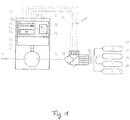
- FIG. 4 shows a schematic drawing of a commercial vehicle air treatment system with a compressor 5 which is driven by an electric motor 3.
- the compressor 5 is driven by the electric motor 3 via a common drive shaft 4 and an electric motor control unit 2. All of these components are arranged in a common housing 1.
- the compressor 5 is a screw compressor 5.
- the air treatment unit 40 which has a multi-circuit protection valve and several compressed air reservoirs 51-54 with stored compressed air 21-24.
- the compressor 5 receives ambient air through the suction line 30 and the outlet is connected to the air treatment unit 40 via an air outlet line 31.
- the following components are integrated in the electric motor control unit 2:
- the frequency converter 6 has a power connection 11 and its output is connected to the electric motor 3 via a corresponding electrical line 12.
- the electric motor control unit 2 is equipped with corresponding signal inputs 7 (analog signal inputs 7) for recording pressure sensor signals and the connections to the solenoid valves 9 in order to be able to perform all functions the air treatment unit 40 to monitor and also the activity of the various pneumatic consumers 50 of the commercial vehicle.
- the analog signal inputs 7 of the electric motor control unit 2 are connected to the air processing device 40 via electrical connections 60.
- the integrated control unit 2 is able to control and activate the frequency converter 6 of the electric motor 3 and also all functions of the air treatment device 40, for which the signal inputs 7 and signal outputs 9 are used.
- Fig. 2 shows in perspective view the in Fig. 1 Commercial vehicle air treatment system shown with the compressor 5, which is driven by the electric motor 3.
- FIG. 2 the air treatment unit 40 and the associated (compressed air) air supply line 64 are shown.
- the electric motor control unit 2 is arranged directly on the electric motor 3.
- the electric motor control unit 2 has two data cable connections 2a and 2b.
- a power connection 2c is also provided.
- the electric motor control unit 2 has a connection 2d for connection to, for example, the CAN bus of a commercial vehicle.
- a first data cable 62 is connected to the data cable connection 2a.
- the electric motor control unit 2 is in signal connection with the electric motor 3 by means of the data transmission cable 62.
- the data transmission cable 62 is connected to an oil level sensor of the screw compressor 3 and is used to transmit oil level sensor data to the electric motor control unit 2.
- a second data cable 63 is connected to the data cable connection 2a.
- the electric motor control unit 2 is also in signal connection with the electric motor 3 by means of the data transmission cable 63.
- the data transmission cable 63 is connected to a temperature sensor of the screw compressor 3 and is used to transmit temperature sensor data to the electric motor control unit 2.
- further sensors can also be connected to the electric motor control unit 2 via the data transmission cables and corresponding operating data of the screw compressor 3 can be transmitted.
- the electric motor control unit 2 which is an integral part of the electric motor 3, is connected to the data bus 66 of the commercial vehicle via the connection.
- the data bus 66 is a CAN bus, which is the CAN bus of the utility vehicle.
- the communication between the electric motor control unit 2, which is part of the electric motor 3, and the air treatment unit 40 thus takes place via the CAN bus 66.
- the air treatment unit 40 has a connection 40a for connection to the CAN bus 66.
- the signal transmission is less susceptible to interference and less interference signals can occur.
- the electric motor 3, the screw compressor 5 and also the air treatment unit 40 are independent units.
- both the electric motor 3 and the air treatment unit 40 are controlled by the electric motor control unit 2 of the electric motor 3.
- Expensive electronic components can thus be saved, namely here in particular in the area of the screw compressor 5, but also in the area of the air treatment unit 40.
- the signal transmission bus here the CAN bus 66
- a particularly advantageous signal transmission for the control of the air treatment unit 40 by the electric motor control unit 2 is made possible.
Landscapes
- Engineering & Computer Science (AREA)
- Mechanical Engineering (AREA)
- General Engineering & Computer Science (AREA)
- Transportation (AREA)
- Chemical & Material Sciences (AREA)
- Oil, Petroleum & Natural Gas (AREA)
- General Chemical & Material Sciences (AREA)
- Chemical Kinetics & Catalysis (AREA)
- Analytical Chemistry (AREA)
- Computer Hardware Design (AREA)
- Control Of Positive-Displacement Pumps (AREA)
- Air-Conditioning For Vehicles (AREA)
- Valves And Accessory Devices For Braking Systems (AREA)
- Compressor (AREA)
Description
- Die vorliegende Erfindung betrifft ein Kompressorsystem für ein Nutzfahrzeug umfassend wenigstens einen Kompressor, wenigstens einen Elektromotor und wenigstens eine Luftaufbereitungseinrichtung.
- Aus dem Stand der Technik sind bereits Luftaufbereitungssysteme für Nutzfahrzeuge bekannt.
- Luftaufbereitungssysteme für Nutzfahrzeuge sind üblicherweise zusammengesetzt aus mehreren Hauptkomponenten wie Luftkompressor, Luftaufbereitungseinheit sowie mehreren Druckluftspeichern.
- Die Anwendung von elektronischen Steuerungseinrichtungen für Luftaufbereitungseinrichtungen (auf englisch: Electronic Control for Air Processing Units (E-APU)) in Nutzfahrzeugen existiert bereits für längere Zeit. Solche Systeme stellen eine Druckkontrolle, eine Lufttrocknungskontrolle und Kreislaufschutzfunktionen bereit.
- Für die Druckkontrolle und die Kreisschutzfunktionalitäten benutzen diese Systeme unterschiedliche Drucksensoren um die Drucklevel zu kontrollieren und zu überwachen und dies in verschiedenen Kreisläufen des Druckluftsystems eines Nutzfahrzeuges. Mehrere Magnetventile werden verwendet um Regeneration und Kompressorkontrollfunktionalitäten zu schaffen.
- Die Steuerung für die Luftaufbereitungseinheit, die neben den genannten Funktionalitäten besteht, kann in die sog. Luftaufbereitungseinheiten mit integriert werden.
- Auch sind mehrere Systeme bekannt, bei denen die Steuerung für die Luftaufbereitungseinheit nicht integriert ist, sondern bei denen diese als externe Lösung ausgebildet ist, so dass nur die Aktuatoren und Drucksensoren in der Luftaufbereitungseinheit untergebracht sind.
- Eine derartige Steuerungseinrichtung ist beispielsweise in der
DE 10 2011 107 155 A1 bekannt. - Es ist die Aufgabe der vorliegenden Erfindung, ein Kompressorsystem für ein Nutzfahrzeug der eingangs genannten Art in vorteilhafter Weise weiterzubilden, insbesondere dahingehend, dass das Kompressorsystem für ein Nutzfahrzeug einfacher aufgebaut sein kann und effizienter ausgestaltet sein kann.
- Diese Aufgabe wird erfindungsgemäß gelöst durch ein Kompressorsystem mit den Merkmalen des Anspruchs 1. Danach ist vorgesehen, dass ein Kompressorsystem für ein Nutzfahrzeug wenigstens einen Kompressor, wenigstens einen Elektromotor, der den Kompressor antreibt, wenigstens eine Elektromotorsteuerungseinheit und wenigstens eine Luftaufbereitungseinrichtung aufweist, wobei die Elektromotorsteuerungseinheit derart beschaffen und eingerichtet ist, dass sie den Elektromotor und zumindest teilweise die Luftaufbereitungseinrichtung steuert.
- Die Erfindung basiert auf dem Grundgedanken, durch eine Funktionsintegration in der Eletromotorsteuerungseinheit sowohl die Steuerungsfunktionalität für den Kompressor als auch für die Luftaufbereitungseinrichtung in der Elektromotorsteuerungseinheit zu integrieren. Hierdurch wird es möglich, die bereits vorhandene leistungsfähige Elektromotorsteuerungseinheit mit weiteren Funktionalitäten zu belegen, so dass eine weitere Steuerungseinheit für die Luftaufbereitungseinrichtung wegfallen kann.
- Des Weiteren kann vorgesehen sein, dass der Kompressor ein Schraubenkompressor ist. Hierdurch ergibt sich der Vorteil, dass eine effiziente und leistungsfähige Druckluftbereitstellung mittels eines Schraubenkompressors möglich ist. Schraubenkompressoren weisen insbesondere in neuen Anwendungsfeldern, wie Hybrid-Nutzfahrzeugen, große Vorteile auf, da sie effizienter betrieben werden können als derzeitige Kompressoren, die davon ausgehen, dass das Antriebsaggregat des Nutzfahrzeugs ständig betrieben wird. Dies ist jedoch bei Hybrid-Nutzfahrzeugen nicht mehr der Fall.
- Darüber hinaus kann vorgesehen sein, dass die Luftaufbereitungseinrichtung ein Mehrkreisschutzventil und mehrere Druckluftspeicher aufweist. Diese Funktionalitäten können ebenfalls durch die Elektromotorsteuerungseinheit mit überwacht und angesteuert werden.
- Außerdem kann vorgesehen sein, dass die Elektromotorsteuerungseinheit Signaleingänge aufweist, die derart beschaffen und eingerichtet sind, dass sie zur Verarbeitung der Sensorsignale der Luftaufbereitungseinrichtung dienen. Mittels dieser Signaleingänge kann einfach erreicht werden, dass die Elektromotorsteuerungseinheit und die Luftaufbereitungseinrichtung miteinander kommunizieren können. Hierzu wird insbesondere vorgesehen, dass die Elektromotorsteuerungseinheit mit den entsprechenden, normierten bzw. gemäß Industriestandard spezifizierten Anschlüssen bzw. Signalanschlüssen versehen wird.
- Die Elektromotorsteuerungseinheit kann Signalausgänge aufweisen, die derart beschaffen und eingerichtet sind, dass sie zur Ansteuerung von Aktuatoren der Luftaufbereitungseinheit dienen. Somit wird es möglich, dass die Luftaufbereitungseinrichtung entsprechend angesteuert werden kann, wobei bei den Aktuatoren insbesondere die Magnetventile oder sonstigen Ventile der Luftaufbereitungseinrichtung anzusteuern sind. Ein effizienter Betrieb der Luftaufbereitungseinrichtung wird hierdurch möglich.
- Darüber hinaus kann vorgesehen sein, dass die Elektromotorsteuerungseinheit ein Drucküberwachungsregelmodul aufweist, das derart beschaffen und eingerichtet ist, dass mittels des Drucküberwachungsregelmoduls der Druck in der Luftaufbereitungseinrichtung überwachbar und/oder regelbar ist. Hierdurch wird es möglich, die Luftaufbereitungseinrichtung in wesentlicher Funktionalität zu überwachen und zu regeln, nämlich im Hinblick auf den in der Luftaufbereitungseinrichtung vorherrschenden Druck und insbesondere den dort vorherrschenden Arbeitsdruck. Anhand dieser Überwachung wird es möglich, die Luftaufbereitungseinrichtung effizient und effektiv betreiben zu können und diese über die Elektromotorsteuerungseinheit mit ihrem Drucküberwachungsregelmodul entsprechend zu überwachen und zu regeln.
- Des Weiteren kann vorgesehen sein, dass das Drucküberwachungsregelmodul weiter derart beschaffen und eingerichtet ist, dass mittels des Drucküberwachungsregelmoduls der Druck in wenigstens einem weiteren Druckluftverbraucher des Nutzfahrzeugs überwachbar und/oder regelbar ist. Dadurch wird es möglich, auch in weiteren Teilen des Druckluftsystems des Nutzfahrzeugs und nicht nur in der Luftaufbereitungseinrichtung eine entsprechende Überwachung und Regelung durch das Drucküberwachungsregelmodul der Elektromotorsteuerungseinheit bereitstellen zu können.
- Des Weiteren kann vorgesehen sein, dass die Elektromotorsteuerungseinheit ein Lufttrocknungsregelmodul aufweist, das derart beschaffen und eingerichtet ist, dass mittels des Lufttrocknungsregelmoduls die Lufttrocknungsfunktion in der Luftaufbereitungseinrichtung überwachbar und/oder regelbar ist. Hierdurch wird es möglich, eine weitere wichtige Funktionalität der Luftaufbereitungseinrichtung überwachen und regel zu können.
- Außerdem ist denkbar, dass die Elektromotorsteuerungseinheit ein Drehzahlregelmodul aufweist, das derart beschaffen und eingerichtet ist, dass mittels des Drehzahlregelmoduls die Drehzahl des Elektromotors steuerbar und/oder regelbar ist. Über die Drehzahlregelung kann die Leistungsaufnahme des Elektromotors und auch der Betrieb des Elektromotors entsprechend gesteuert und auch eingeregelt werden. Dies kann belastungsgerecht und unmittelbar erfolgen.
- Weitere Einzelheiten und Vorteile der Erfindung sollen nun anhand eines in den Zeichnungen dargestellten Ausführungsbeispiels näher erläutert werden.
- Es zeigen:
- Fig. 1
- eine schematische Ansicht einer Luftaufbereitungseinrichtung für ein Nutzfahrzeug; und
- Fig. 2
- eine perspektivische Anordnung auf das Ausführungsbeispiel gemäß
Fig. 1 . -
Fig. 1 zeigt eine schematische Zeichnung eines Nutzfahrzeugluftaufbereitungssystems mit einem Kompressor 5, der durch einen Elektromotor 3 angetrieben wird. - Der Antrieb des Kompressors 5 über den Elektromotor 3 erfolgt über eine gemeinsame Antriebswelle 4 und eine Elektromotorsteuerungseinheit 2. Alle diese Komponenten sind in einem gemeinsamen Gehäuse 1 angeordnet.
- Bei dem Kompressor 5 handelt es sich um einen Schraubenkompressor 5.
- Darüber hinaus ist die Luftaufbereitungseinheit 40 vorhanden, die ein Mehrkreisschutzventil und mehrere Druckluftspeicher 51-54 mit eingespeicherter Druckluft 21-24 aufweist.
- Der Kompressor 5 erhält Umgebungsluft durch die Ansaugleitung 30 und der Auslass ist verbunden mit der Luftaufbereitungseinheit 40 über eine Luftauslassleitung 31.
- In der Elektromotorsteuerungseinheit 2 sind die folgenden Bestandteile integriert:
Die Kontrolleinheit 10 für die Luftaufbereitungseinrichtung 40 (A. 10) und die Kontrolleinheit 10 für den Frequenzeinheitumrechner 6 für den Elektromotor 3, die mit einander verbunden sind über eine elektrische Kontrollleitung 30. - Der Frequenzumrechner 6 hat einen Energieanschluss 11 und sein Ausgang ist verbunden mit dem Elektromotor 3 über eine entsprechende elektrische Leitung 12.
- Die Elektromotorsteuerungseinehit 2 ist ausgestattet mit entsprechenden Signaleingängen 7 (analoge Signaleingänge 7) für die Drucksensorensignalaufnahme und die Anschlüsse zu den Magnetventilen 9, um in der Lage zu sein, alle Funktionen der Luftaufbereitungseinheit 40 zu überwachen und auch die Tätigkeit der verschiedenen pneumatischen Verbraucher 50 des Nutzfahrzeugs.
- Die analogen Signaleingänge 7 der Elektromotorsteuerungseinheit 2 sind mit der Luftaufbearbeitungseinrichtung 40 über elektrische Anschlüsse 60 verbunden.
- Gleiches gilt für die Ventilantriebe 9, die ebenfalls entsprechend verbunden sind über Anschlussleitungen 61.
- Die integrierte Steuerungseinheit 2 ist in der Lage, den Frequenzumrechner 6 des Elektromotors 3 zu kontrollieren und anzusteuern und auch sämtliche Funktionen der Luftaufbereitungseinrichtung 40, wozu die Signaleingänge 7 und Signalausgänge 9 verwendet werden.
- Mithilfe dieser Anschlüsse 7 und 9 wird es möglich, die Drucksituation in der Luftaufbereitungseinrichtung 40 und die Lufttrocknungsfunktion entsprechend kontrollieren zu können.
- Darüber hinaus ist es möglich, den Fahrzeugstatus, den Elektromotorstatus und auch den Luftaufbereitungsstatus entsprechend zu überwachen und eine entsprechende Drehzahl an den Elektromotor 3 abzugeben, um eine optimale und bestmögliche Betriebscharakteristik für den Kompressor 5 bereitstellen zu können.
-
Fig. 2 zeigt in perspektivischer Ansicht das inFig. 1 gezeigte Nutzfahrzeugluftaufbereitungssystem mit dem Kompressor 5, der durch den Elektromotor 3 angetrieben wird. - Weiter ist in
Fig. 2 die Luftaufbereitungseinheit 40 sowie die zugehörige (Druckluft- )Luftversorgungsleitung 64 gezeigt. - Die Elektromotorsteuerungseinheit 2 ist dabei direkt auf dem Elektromotor 3 angeordnet.
- Die Elektromotorsteuerungseinheit 2 weist dabei zwei Datenkabelanschlüsse 2a und 2b auf.
- Weiter ist ein Stromanschluss 2c vorgesehen.
- Außerdem weist die Elektromotorsteuerungseinheit 2 einen Anschluss 2d zur Verbindung mit z.B. dem CAN-Bus eines Nutzfahrzeugs auf.
- Am Datenkabelanschluss 2a ist ein erstes Datenkabel 62 angeschlossen.
- Mittels des Datenübertragungskabels 62 ist die Elektromotorsteuerungseinheit 2 mit dem Elektromotor 3 in Signalverbindung.
- Im gezeigten Ausführungsbeispiel ist das Datenübertragungskabel 62 mit einem Öllevelsensor des Schraubenkompressors 3 verbunden und dient zur Übertragung von Öllevelsensordaten an die Elektromotorsteuerungseinheit 2.
- Am Datenkabelanschluss 2a ist ein zweites Datenkabel 63 angeschlossen.
- Auch mittels des Datenübertragungskabels 63 ist die Elektromotorsteuerungseinheit 2 mit dem Elektromotor 3 in Signalverbindung.
- Im gezeigten Ausführungsbeispiel ist das Datenübertragungskabel 63 mit einem Temperatursensor des Schraubenkompressors 3 verbunden und dient zur Übertragung von Temperatursensordaten an die Elektromotorsteuerungseinheit 2.
- Grundsätzlich können über die Datenübertragungskabel auch weitere Sensoren mit der Elektromotorsteuerungseinheit 2 verbunden und entsprechende Betriebsdaten des Schraubenkompressors 3 übertragen werden.
- Des Weiteren ist die Elektromotorsteuerungseinheit 2, die integraler Bestandteil des Elektromotors 3 ist, über den Anschluss mit dem Datenbus 66 des Nutzfahrzeugs verbunden.
- Bei dem Datenbus 66 handelt es sich hier im gezeigten Ausführungsbeispiel um einen CAN-Bus, der der CAN-Bus des Nutzfahrzeugs ist.
- Die Kommunikation zwischen der Elektromotorsteuerungseinheit 2, die Bestandteil des Elektromotors 3 ist, und der Luftaufbereitungseinheit 40 erfolgt somit über den CAN-Bus 66.
- Die Luftaufbereitungseinheit 40 weist einen Anschluss 40a zum Anschluss an den CAN-Bus 66 auf.
- Durch die Nutzung des CAN-Bus 66 wird erreicht, dass die Signalübertragung weniger störanfällig ist und auch weniger Störsignale auftreten können.
- Insbesondere kann mit deutlich kürzeren Leitungen zur Signalübertragung von der Elektromotorsteuerungseinheit 2 zum CAN-Bus 66 und vom CAN-Bus 66 hin zur Luftaufbereitungseinheit 40 gearbeitet werden, wodurch eine Funktionsintegration und auch eine Nutzung der bestehenden ohnehin vorhandenen Signalübertragungsinfrastruktur des Nutzfahrzeugs möglich wird.
- Wie dies aus
Fig. 1 undFig. 2 ersichtlich ist, sind der Elektromotor 3, der Schraubenkompressor 5 und auch die Luftaufbereitungseinheit 40 eigenständige Einheiten. - Allerdings werden durch die Elektromotorsteuerungseinheit 2 des Elektromotors 3 sowohl der Elektromotor 3 als auch die Luftaufbereitungseinheit 40 angesteuert.
- Es erfolgt somit eine Funktionsintegration der Steuerung und Regelung für den Schraubenkompressor 5 und die Luftaufbereitung 40 in der Steuerungseinheit 2 des Elektromotors 3, die ohnehin mit einer leistungsstarken Steuerungs- und Regelungseinheit versehen sein muss.
- Somit können teure Elektronikkomponenten eingespart werden, nämlich hier insbesondere im Bereich des Schraubenkompressors 5, aber auch im Bereich der Luftaufbereitungseinheit 40.
- Durch die Nutzung des Signalübertragungsbusses, hier des CAN-Bus 66, wird weiter eine besonders vorteilhafte Signalübertragung für die Ansteuerung der Luftaufbereitungseinheit 40 durch die Elektromotorsteuerungseinheit 2 ermöglicht.
-
- 1
- Gehäuse
- 2
- Elektromotorsteuerungseinheit
- 2a
- Datenkabelanschluss
- 2b
- Datenkabelanschluss
- 2c
- Stromanschluss
- 2d
- Anschluss
- 3
- Elektromotor
- 4
- Antriebswelle
- 5
- Kompressor
- 6
- Frequenzeinheitumrechner
- 7
- Signaleingänge
- 9
- Magnetventil
- 10
- Kontrolleinheit
- 11
- Energieanschluss
- 12
- elektrische Leitung
- 21
- Druckluft
- 22
- Druckluft
- 23
- Druckluft
- 24
- Druckluft
- 30
- Ansaugleitung / Kontrollleitung
- 31
- Luftauslassleitung
- 40
- Luftaufbereitungseinheit
- 40a
- Anschluss
- 50
- pneumatischer Verbraucher
- 51
- Druckluftspeicher
- 52
- Druckluftspeicher
- 53
- Druckluftspeicher
- 54
- Druckluftspeicher
- 60
- elektrische Anschlüsse
- 61
- Anschlussleitungen
- 62
- Datenübertragungskabel
- 63
- Datenübertragungskabel
- 64
- (Druckluft-)Luftversorgungsleitung
- 66
- Datenbus, CAN-Bus
Claims (9)
- Kompressorsystem für ein Nutzfahrzeug aufweisend wenigstens einen Kompressor (5), wenigstens einen Elektromotor (3), der den Kompressor (5) antreibt, wenigstens eine Elektromotorsteuerungseinheit (2) und wenigstens eine Luftaufbereitungseinrichtung (40),
dadurch gekennzeichnet, dass
die Elektromotorsteuerungseinheit (2) derart beschaffen und eingerichtet ist, dass sie den Elektromotor (3) und zumindest teilweise die Luftaufbereitungseinrichtung (40) steuert. - Kompressorsystem nach Anspruch 1,
dadurch gekennzeichnet, dass
der Kompressor (5) ein Schraubenkompressor (5) ist. - Kompressorsystem nach Anspruch 1 und Anspruch 2,
dadurch gekennzeichnet, dass
die Luftaufbereitungseinrichtung (40) ein Mehrkreisschutzventil und mehrere Druckluftspeicher (51-54) aufweist. - Kompressorsystem nach einem der vorhergehenden Ansprüche,
dadurch gekennzeichnet, dass
die Elektromotorsteuerungseinheit (2) Signaleingänge (7) aufweist, die derart beschaffen und eingerichtet sind, dass sie zur Verarbeitung der Sensorsignale der Luftaufbereitungseinrichtung (40) dienen. - Kompressorsystem nach einem der vorhergehenden Ansprüche,
dadurch gekennzeichnet, dass
die Elektromotorsteuerungseinheit (2) Signalausgänge (9) aufweist, die derart beschaffen und eingerichtet sind, dass sie zur Ansteuerung von Aktuatoren der Luftaufbereitungseinrichtung (40) dienen. - Kompressorsystem nach einem der vorhergehenden Ansprüche,
dadurch gekennzeichnet, dass
die Elektromotorsteuerungseinheit (2) ein Drucküberwachungsregelmodul aufweist, das derart beschaffen und eingerichtet ist, dass mittels des Drucküberwachungsregelmoduls der Druck in der Luftaufbereitungseinrichtung (40) überwachbar und/oder regelbar ist. - Kompressorsystem nach Anspruch 6,
dadurch gekennzeichnet, dass
das Drucküberwachungsregelmodul weiter derart beschaffen und eingerichtet ist, dass mittels des Drucküberwachungsregelmoduls der Druck in wenigstens einem weiteren Druckluftverbraucher des Nutzfahrzeugs überwachbar und/oder regelbar ist. - Kompressorsystem nach einem der vorhergehenden Ansprüche,
dadurch gekennzeichnet, dass
die Elektromotorsteuerungseinheit (2) ein Lufttrocknungsregelmodul aufweist, das derart beschaffen und eingerichtet ist, dass mittels des Lufttrocknungsregelmoduls die Lufttrocknungsfunktion in der Luftaufbereitungseinrichtung (40) überwachbar und/oder regelbar ist. - Kompressorsystem nach einem der vorhergehenden Ansprüche,
dadurch gekennzeichnet, dass
die Elektromotorsteuerungseinheit (2) ein Drehzahlregelmodul aufweist, das derart beschaffen und eingerichtet ist, dass mittels des Drehzahlregelmoduls die Drehzahl des Elektromotors (3) steuerbar und/oder regelbar ist.
Applications Claiming Priority (2)
| Application Number | Priority Date | Filing Date | Title |
|---|---|---|---|
| DE102016011502.5A DE102016011502A1 (de) | 2016-09-21 | 2016-09-21 | Kompressorsystem für ein Nutzfahrzeug |
| PCT/EP2017/073554 WO2018054869A1 (de) | 2016-09-21 | 2017-09-19 | Kompressorsystem für ein nutzfahrzeug |
Publications (2)
| Publication Number | Publication Date |
|---|---|
| EP3516218A1 EP3516218A1 (de) | 2019-07-31 |
| EP3516218B1 true EP3516218B1 (de) | 2021-03-17 |
Family
ID=59923434
Family Applications (1)
| Application Number | Title | Priority Date | Filing Date |
|---|---|---|---|
| EP17771417.7A Revoked EP3516218B1 (de) | 2016-09-21 | 2017-09-19 | Kompressorsystem für ein nutzfahrzeug |
Country Status (8)
| Country | Link |
|---|---|
| US (1) | US20190309745A1 (de) |
| EP (1) | EP3516218B1 (de) |
| JP (1) | JP2019529249A (de) |
| KR (1) | KR102222347B1 (de) |
| CN (1) | CN109923311B (de) |
| BR (1) | BR112019005105A2 (de) |
| DE (1) | DE102016011502A1 (de) |
| WO (1) | WO2018054869A1 (de) |
Cited By (3)
| Publication number | Priority date | Publication date | Assignee | Title |
|---|---|---|---|---|
| DE102022112936A1 (de) | 2022-05-23 | 2023-11-23 | Zf Cv Systems Global Gmbh | Drucklufterzeugungsvorrichtung und Verfahren zum Betreiben derselben |
| DE102022112935A1 (de) | 2022-05-23 | 2023-11-23 | Zf Cv Systems Global Gmbh | Drucklufterzeugungsvorrichtung und Verfahren zum Betreiben derselben |
| DE102022112934A1 (de) | 2022-05-23 | 2023-11-23 | Zf Cv Systems Global Gmbh | Drucklufterzeugungsvorrichtung und Verfahren zum Betreiben derselben |
Families Citing this family (3)
| Publication number | Priority date | Publication date | Assignee | Title |
|---|---|---|---|---|
| KR102681632B1 (ko) * | 2019-02-15 | 2024-07-08 | 현대자동차주식회사 | 수밀 챔버형 전동 진공펌프 및 진공 배력 브레이크 시스템 |
| EP4223599B1 (de) | 2022-02-07 | 2025-07-02 | ZF CV Systems Europe BV | Luftzufuhrsystem und verfahren zur steuerung seines betriebs, pneumatisches system, fahrzeug und computerprogramm |
| KR102604958B1 (ko) * | 2022-12-23 | 2023-11-22 | 지에프 씨브이 시스템즈 유럽 비브이 | 차량 제동용 공기 압축기 |
Citations (36)
| Publication number | Priority date | Publication date | Assignee | Title |
|---|---|---|---|---|
| WO1996034785A1 (de) | 1995-04-29 | 1996-11-07 | Robert Bosch Gmbh | Druckluft-versorgungseinrichtung für fahrzeug-druckluftanlagen sowie verfahren zum steuern der druckluft-versorgungseinrichtung |
| US6461112B1 (en) | 2000-06-02 | 2002-10-08 | Hitachi, Ltd. | Screw compression apparatus and operation control method thereof |
| JP2004112921A (ja) | 2002-09-19 | 2004-04-08 | Hitachi Industrial Equipment Systems Co Ltd | 燃料電池駆動式鉄道車両及び燃料電池駆動式鉄道車両ユニット |
| DE10252975A1 (de) | 2002-11-14 | 2004-06-03 | Knorr-Bremse Systeme für Nutzfahrzeuge GmbH | Kompressoranordnung mit einer Zusatzverdichtereinheit, insbesondere für Nutzfahrzeuge |
| DE102004032458A1 (de) | 2004-06-30 | 2006-01-26 | Volkswagen Ag | Vorrichtung und Verfahren zur Ansteuerung von Systemkomponenten |
| DE102005010960A1 (de) | 2005-03-10 | 2006-09-28 | Audi Ag | Niveauregulierungssystem für ein Kraftfahrzeug |
| EP1961960A2 (de) | 2007-02-22 | 2008-08-27 | WABCO GmbH | Verfahren zur Steuerung eines Kompressors und Vorrichtung zur Durchführung des Verfahrens |
| DE102008009473A1 (de) | 2008-02-15 | 2009-08-20 | Robert Bosch Gmbh | Vorrichtung und Verfahren zum Befüllen von aufblasbaren Fahrzeugsitz-Polsterelementen |
| US20090254246A1 (en) | 2008-04-02 | 2009-10-08 | International Truck Intellectual Property Company, Llc | Method and apparatus to optimize energy efficiency of air compressor in vehicle air brake application |
| US7632076B2 (en) | 2005-03-02 | 2009-12-15 | Bendix Commercial Vehicle Systems Llc | Air supply system control |
| JP2010105584A (ja) | 2008-10-31 | 2010-05-13 | Hitachi Automotive Systems Ltd | 車高制御装置 |
| CN201834002U (zh) | 2010-04-23 | 2011-05-18 | 北汽福田汽车股份有限公司 | 一种汽车制动系统及带有此种制动系统的汽车 |
| WO2011093135A1 (ja) | 2010-01-26 | 2011-08-04 | ナブテスコ株式会社 | 鉄道車両用空気圧縮装置 |
| DE102010024476A1 (de) | 2010-06-21 | 2011-12-22 | Wabco Gmbh | Druckluftsteuerungseinrichtung, Druckluftsteuerungsverfahren, elektronische Steuereinrichtung, Druckluftversorgungssystem, Druckluftversorgungsverfahren und Fahrzeug |
| DE102010036742A1 (de) | 2010-07-29 | 2012-02-02 | Continental Teves Ag & Co. Ohg | Lufttrockner einer Luftversorgungsanlage |
| CN202186346U (zh) * | 2011-08-30 | 2012-04-11 | 瑞立集团瑞安汽车零部件有限公司 | 一种车辆电控空气处理系统、气动系统和车辆 |
| WO2012128770A1 (en) * | 2011-03-24 | 2012-09-27 | International Truck Intellectual Property Company, Llc | Control system for vehicle equipped for regenerative braking |
| DE102011107155A1 (de) | 2011-07-14 | 2013-01-17 | Knorr-Bremse Systeme für Nutzfahrzeuge GmbH | Druckluftaufbereitungsanlage und Verfahren zum Betreiben einer Druckluftaufbereitungsanlage |
| DE102012200412A1 (de) | 2012-01-12 | 2013-07-18 | Continental Teves Ag & Co. Ohg | Verfahren zur Optimierung einer Befüllung eines geschlossenen Luftversorgungssystems einer geschlossenen Niveauregelanlage |
| DE102006023632B4 (de) | 2006-05-19 | 2013-08-01 | Knorr-Bremse Systeme für Nutzfahrzeuge GmbH | Druckluftversorgungseinrichtung für ein Nutzfahrzeug |
| CN103241235A (zh) | 2013-05-28 | 2013-08-14 | 湖南南车时代电动汽车股份有限公司 | 电动汽车空压机及制动开关气路控制方法及气路控制系统 |
| WO2013167217A2 (de) | 2012-05-10 | 2013-11-14 | Wabco Gmbh | Verfahren zum betrieb einer druckluftbremsanlage |
| CN103437986A (zh) | 2013-08-30 | 2013-12-11 | 中通客车控股股份有限公司 | 一种气路及电动空气压缩机综合控制系统及控制方法 |
| DE102012021597A1 (de) * | 2012-11-02 | 2014-05-08 | Wabco Gmbh | Verfahren zur Druckluftaufbereitung in Kraftfahrzeugen und Einrichtung zur Durchführung dieses Verfahrens |
| DE102013101502A1 (de) | 2013-02-14 | 2014-08-14 | Knorr-Bremse Systeme für Schienenfahrzeuge GmbH | Luftversorgungsanlage mit elektronischem Umrichter |
| DE102013113555A1 (de) | 2013-12-05 | 2015-06-11 | Knorr-Bremse Systeme für Schienenfahrzeuge GmbH | Kompressorsystem und Verfahren zum Betrieb des Kompressorsystems in Abhängigkeit vom Betriebszustand des Schienenfahrzeugs |
| DE102013114304A1 (de) | 2013-12-18 | 2015-06-18 | Knorr-Bremse Systeme für Nutzfahrzeuge GmbH | Kompressorsystem mit einer Kolbenhubeinstellvorrichtung |
| DE102014207509A1 (de) | 2014-04-17 | 2015-10-22 | Continental Teves Ag & Co. Ohg | Integrierte Luftversorgungseinheit |
| WO2015176871A1 (en) | 2014-05-20 | 2015-11-26 | Jaguar Land Rover Limited | Central tyre inflation system and method |
| US20150345490A1 (en) | 2012-12-13 | 2015-12-03 | Wabco Gmbh | Compressor for Producing Compressed Air, Compressed Air Supply System, Pneumatic System and Method for Operating a Compressor |
| WO2015197161A1 (de) | 2014-06-23 | 2015-12-30 | Wilo Se | Nassläufermotorpumpe |
| DE102014009420A1 (de) | 2014-06-25 | 2015-12-31 | Wabco Gmbh | Druckluftversorgungsanlage, pneumatisches System und Verfahren zum Steuern einer Druckluftversorgungsanlage |
| CN105365578A (zh) | 2015-11-23 | 2016-03-02 | 潍柴动力股份有限公司 | 纯电动汽车电动空气压缩机系统及其控制方法、电动汽车 |
| CN105822531A (zh) * | 2016-05-06 | 2016-08-03 | 清华大学 | 采用改进组合干燥器的电动制动空压机系统启停控制方法 |
| WO2016198590A1 (en) | 2015-06-12 | 2016-12-15 | Jaguar Land Rover Limited | Control system, vehicle and method |
| WO2017042140A1 (de) | 2015-09-11 | 2017-03-16 | Knorr-Bremse Systeme für Schienenfahrzeuge GmbH | Verfahren und einrichtung zur steuerung einer lufttrocknereinheit einer luftversorgungsanlage für die haupt- und hilfsluftversorgung, insbesondere für ein schienenfahrzeug |
Family Cites Families (11)
| Publication number | Priority date | Publication date | Assignee | Title |
|---|---|---|---|---|
| SE9400575L (sv) * | 1994-02-18 | 1995-08-19 | Volvo Ab | Anordning för uppladdning av luftsystem på lastfordon |
| JP2008184131A (ja) * | 2007-01-31 | 2008-08-14 | Hitachi Ltd | 車載圧縮装置及びその制御方法 |
| DE102009002315A1 (de) * | 2009-04-09 | 2010-10-14 | Robert Bosch Gmbh | Steuervorrichtungen für ein bremskraftverstärktes Bremssystem eines Fahrzeugs und Verfahren zum Betreiben eines bremskraftverstärkten Bremssystems eines Fahrzeugs |
| JP5489825B2 (ja) * | 2010-02-10 | 2014-05-14 | ナブテスコ株式会社 | 鉄道車両用空気圧縮装置 |
| DE102010054063A1 (de) * | 2010-12-10 | 2012-06-14 | Wabco Gmbh | Luftaufbereitungseinheit für ein Druckluftsystem eines Fahrzeuges |
| DE102011076785A1 (de) * | 2011-05-31 | 2012-12-06 | Robert Bosch Gmbh | Steuervorrichtung für eine elektrische Vakuumpumpe und Verfahren zum Ansteuern einer elektrischen Vakuumpumpe |
| CN202294764U (zh) * | 2011-09-26 | 2012-07-04 | 金龙联合汽车工业(苏州)有限公司 | 用于客车的气压制动系统 |
| CN202703565U (zh) * | 2012-07-10 | 2013-01-30 | 江苏大学 | 用于纯电动汽车回收利用电动真空泵排气的气体管理系统 |
| WO2015170737A1 (ja) * | 2014-05-09 | 2015-11-12 | ナブテスコオートモーティブ 株式会社 | 圧縮空気乾燥装置、圧縮空気乾燥装置の制御方法及び車両 |
| DE102015219613A1 (de) | 2015-10-09 | 2017-04-13 | Continental Teves Ag & Co. Ohg | Integrierte Luftversorgungseinheit mit Lufttrockner und Luftfedersystem, sowie Steuerung einer Luftversorgungseinheit |
| DE102015220743A1 (de) * | 2015-10-23 | 2017-04-27 | Deere & Company | System zur Beeinflussung einer Fahrzeuglage |
-
2016
- 2016-09-21 DE DE102016011502.5A patent/DE102016011502A1/de not_active Ceased
-
2017
- 2017-09-19 WO PCT/EP2017/073554 patent/WO2018054869A1/de not_active Ceased
- 2017-09-19 JP JP2019536676A patent/JP2019529249A/ja active Pending
- 2017-09-19 CN CN201780068680.2A patent/CN109923311B/zh active Active
- 2017-09-19 BR BR112019005105A patent/BR112019005105A2/pt not_active Application Discontinuation
- 2017-09-19 EP EP17771417.7A patent/EP3516218B1/de not_active Revoked
- 2017-09-19 KR KR1020197010754A patent/KR102222347B1/ko active Active
- 2017-09-19 US US16/333,154 patent/US20190309745A1/en active Pending
Patent Citations (37)
| Publication number | Priority date | Publication date | Assignee | Title |
|---|---|---|---|---|
| WO1996034785A1 (de) | 1995-04-29 | 1996-11-07 | Robert Bosch Gmbh | Druckluft-versorgungseinrichtung für fahrzeug-druckluftanlagen sowie verfahren zum steuern der druckluft-versorgungseinrichtung |
| US6461112B1 (en) | 2000-06-02 | 2002-10-08 | Hitachi, Ltd. | Screw compression apparatus and operation control method thereof |
| JP2004112921A (ja) | 2002-09-19 | 2004-04-08 | Hitachi Industrial Equipment Systems Co Ltd | 燃料電池駆動式鉄道車両及び燃料電池駆動式鉄道車両ユニット |
| DE10252975A1 (de) | 2002-11-14 | 2004-06-03 | Knorr-Bremse Systeme für Nutzfahrzeuge GmbH | Kompressoranordnung mit einer Zusatzverdichtereinheit, insbesondere für Nutzfahrzeuge |
| DE102004032458A1 (de) | 2004-06-30 | 2006-01-26 | Volkswagen Ag | Vorrichtung und Verfahren zur Ansteuerung von Systemkomponenten |
| US7632076B2 (en) | 2005-03-02 | 2009-12-15 | Bendix Commercial Vehicle Systems Llc | Air supply system control |
| DE102005010960A1 (de) | 2005-03-10 | 2006-09-28 | Audi Ag | Niveauregulierungssystem für ein Kraftfahrzeug |
| DE102006023632B4 (de) | 2006-05-19 | 2013-08-01 | Knorr-Bremse Systeme für Nutzfahrzeuge GmbH | Druckluftversorgungseinrichtung für ein Nutzfahrzeug |
| EP1961960A2 (de) | 2007-02-22 | 2008-08-27 | WABCO GmbH | Verfahren zur Steuerung eines Kompressors und Vorrichtung zur Durchführung des Verfahrens |
| DE102008009473A1 (de) | 2008-02-15 | 2009-08-20 | Robert Bosch Gmbh | Vorrichtung und Verfahren zum Befüllen von aufblasbaren Fahrzeugsitz-Polsterelementen |
| US20090254246A1 (en) | 2008-04-02 | 2009-10-08 | International Truck Intellectual Property Company, Llc | Method and apparatus to optimize energy efficiency of air compressor in vehicle air brake application |
| US8260494B2 (en) | 2008-04-02 | 2012-09-04 | International Truck Intellectual Property Company, Llc | Method and apparatus to optimize energy efficiency of air compressor in vehicle air brake application |
| JP2010105584A (ja) | 2008-10-31 | 2010-05-13 | Hitachi Automotive Systems Ltd | 車高制御装置 |
| WO2011093135A1 (ja) | 2010-01-26 | 2011-08-04 | ナブテスコ株式会社 | 鉄道車両用空気圧縮装置 |
| CN201834002U (zh) | 2010-04-23 | 2011-05-18 | 北汽福田汽车股份有限公司 | 一种汽车制动系统及带有此种制动系统的汽车 |
| DE102010024476A1 (de) | 2010-06-21 | 2011-12-22 | Wabco Gmbh | Druckluftsteuerungseinrichtung, Druckluftsteuerungsverfahren, elektronische Steuereinrichtung, Druckluftversorgungssystem, Druckluftversorgungsverfahren und Fahrzeug |
| DE102010036742A1 (de) | 2010-07-29 | 2012-02-02 | Continental Teves Ag & Co. Ohg | Lufttrockner einer Luftversorgungsanlage |
| WO2012128770A1 (en) * | 2011-03-24 | 2012-09-27 | International Truck Intellectual Property Company, Llc | Control system for vehicle equipped for regenerative braking |
| DE102011107155A1 (de) | 2011-07-14 | 2013-01-17 | Knorr-Bremse Systeme für Nutzfahrzeuge GmbH | Druckluftaufbereitungsanlage und Verfahren zum Betreiben einer Druckluftaufbereitungsanlage |
| CN202186346U (zh) * | 2011-08-30 | 2012-04-11 | 瑞立集团瑞安汽车零部件有限公司 | 一种车辆电控空气处理系统、气动系统和车辆 |
| DE102012200412A1 (de) | 2012-01-12 | 2013-07-18 | Continental Teves Ag & Co. Ohg | Verfahren zur Optimierung einer Befüllung eines geschlossenen Luftversorgungssystems einer geschlossenen Niveauregelanlage |
| WO2013167217A2 (de) | 2012-05-10 | 2013-11-14 | Wabco Gmbh | Verfahren zum betrieb einer druckluftbremsanlage |
| DE102012021597A1 (de) * | 2012-11-02 | 2014-05-08 | Wabco Gmbh | Verfahren zur Druckluftaufbereitung in Kraftfahrzeugen und Einrichtung zur Durchführung dieses Verfahrens |
| US20150345490A1 (en) | 2012-12-13 | 2015-12-03 | Wabco Gmbh | Compressor for Producing Compressed Air, Compressed Air Supply System, Pneumatic System and Method for Operating a Compressor |
| DE102013101502A1 (de) | 2013-02-14 | 2014-08-14 | Knorr-Bremse Systeme für Schienenfahrzeuge GmbH | Luftversorgungsanlage mit elektronischem Umrichter |
| CN103241235A (zh) | 2013-05-28 | 2013-08-14 | 湖南南车时代电动汽车股份有限公司 | 电动汽车空压机及制动开关气路控制方法及气路控制系统 |
| CN103437986A (zh) | 2013-08-30 | 2013-12-11 | 中通客车控股股份有限公司 | 一种气路及电动空气压缩机综合控制系统及控制方法 |
| DE102013113555A1 (de) | 2013-12-05 | 2015-06-11 | Knorr-Bremse Systeme für Schienenfahrzeuge GmbH | Kompressorsystem und Verfahren zum Betrieb des Kompressorsystems in Abhängigkeit vom Betriebszustand des Schienenfahrzeugs |
| DE102013114304A1 (de) | 2013-12-18 | 2015-06-18 | Knorr-Bremse Systeme für Nutzfahrzeuge GmbH | Kompressorsystem mit einer Kolbenhubeinstellvorrichtung |
| DE102014207509A1 (de) | 2014-04-17 | 2015-10-22 | Continental Teves Ag & Co. Ohg | Integrierte Luftversorgungseinheit |
| WO2015176871A1 (en) | 2014-05-20 | 2015-11-26 | Jaguar Land Rover Limited | Central tyre inflation system and method |
| WO2015197161A1 (de) | 2014-06-23 | 2015-12-30 | Wilo Se | Nassläufermotorpumpe |
| DE102014009420A1 (de) | 2014-06-25 | 2015-12-31 | Wabco Gmbh | Druckluftversorgungsanlage, pneumatisches System und Verfahren zum Steuern einer Druckluftversorgungsanlage |
| WO2016198590A1 (en) | 2015-06-12 | 2016-12-15 | Jaguar Land Rover Limited | Control system, vehicle and method |
| WO2017042140A1 (de) | 2015-09-11 | 2017-03-16 | Knorr-Bremse Systeme für Schienenfahrzeuge GmbH | Verfahren und einrichtung zur steuerung einer lufttrocknereinheit einer luftversorgungsanlage für die haupt- und hilfsluftversorgung, insbesondere für ein schienenfahrzeug |
| CN105365578A (zh) | 2015-11-23 | 2016-03-02 | 潍柴动力股份有限公司 | 纯电动汽车电动空气压缩机系统及其控制方法、电动汽车 |
| CN105822531A (zh) * | 2016-05-06 | 2016-08-03 | 清华大学 | 采用改进组合干燥器的电动制动空压机系统启停控制方法 |
Cited By (6)
| Publication number | Priority date | Publication date | Assignee | Title |
|---|---|---|---|---|
| DE102022112936A1 (de) | 2022-05-23 | 2023-11-23 | Zf Cv Systems Global Gmbh | Drucklufterzeugungsvorrichtung und Verfahren zum Betreiben derselben |
| DE102022112935A1 (de) | 2022-05-23 | 2023-11-23 | Zf Cv Systems Global Gmbh | Drucklufterzeugungsvorrichtung und Verfahren zum Betreiben derselben |
| DE102022112934A1 (de) | 2022-05-23 | 2023-11-23 | Zf Cv Systems Global Gmbh | Drucklufterzeugungsvorrichtung und Verfahren zum Betreiben derselben |
| WO2023227269A1 (de) | 2022-05-23 | 2023-11-30 | Zf Cv Systems Global Gmbh | Drucklufterzeugungsvorrichtung und verfahren zum betreiben derselben |
| WO2023227268A1 (de) | 2022-05-23 | 2023-11-30 | Zf Cv Systems Global Gmbh | Drucklufterzeugungsvorrichtung und verfahren zum betreiben derselben |
| WO2023227267A1 (de) | 2022-05-23 | 2023-11-30 | Zf Cv Systems Global Gmbh | Drucklufterzeugungsvorrichtung und verfahren zum betreiben derselben |
Also Published As
| Publication number | Publication date |
|---|---|
| EP3516218A1 (de) | 2019-07-31 |
| KR20190045365A (ko) | 2019-05-02 |
| WO2018054869A1 (de) | 2018-03-29 |
| DE102016011502A1 (de) | 2018-03-22 |
| JP2019529249A (ja) | 2019-10-17 |
| US20190309745A1 (en) | 2019-10-10 |
| KR102222347B1 (ko) | 2021-03-02 |
| BR112019005105A2 (pt) | 2019-06-04 |
| CN109923311B (zh) | 2021-04-30 |
| CN109923311A (zh) | 2019-06-21 |
Similar Documents
| Publication | Publication Date | Title |
|---|---|---|
| EP3516218B1 (de) | Kompressorsystem für ein nutzfahrzeug | |
| EP2956341B1 (de) | Luftversorgungsanlage mit elektronischem umrichter | |
| EP3127192B1 (de) | Modularer steckverbinder | |
| EP3013624B1 (de) | Druckluftsystem | |
| EP0803653B1 (de) | Pneumatische Betätigungsanordnung | |
| EP0275992A2 (de) | Maschinenanlage mit mehreren Aktoren | |
| DE102012109206B4 (de) | Ventil-Sensor-Anordnung | |
| DE20009207U1 (de) | Einrichtung zur Signalübertragung | |
| EP2865899B1 (de) | Druckluft-Wartungsgerät, damit ausgestattete Verbrauchersteuervorrichtung und zugehöriges Betriebsverfahren | |
| DE10012405A1 (de) | Einrichtung zur Steuerung eines hydraulischen Aktuators | |
| EP3192618A1 (de) | Verfahren zum betreiben einer pneumatisch angetriebenen anlage zur handhabung von werkstücken sowie anlage zur handhabung von werkstücken | |
| EP4039550B1 (de) | Schnittstellenelement für ein fahrzeug | |
| EP2079086B1 (de) | Elektrische Transformator-Einheit | |
| DE102005048646B3 (de) | Steuereinrichtung für wenigstens einen fluidischen Aktor | |
| EP3350455A1 (de) | Ventilsteuerung und verfahren zum betreiben einer ventilsteuerung | |
| DE102016106595A1 (de) | Großmanipulator mit dezentraler Hydraulik | |
| EP2728205A2 (de) | Druckluft-Wartungsgerät und damit ausgestattete Verbrauchersteuervorrichtung | |
| EP3099548B1 (de) | Druckluftversorgungssystem für nutzfahrzeuge | |
| DE4327651A1 (de) | Steuermodul für eine verstellbare Hydromaschine | |
| DE102015223614B4 (de) | Geschlossene niveauregelnde Anlage für Fahrzeuge mit druckgeregeltem Zusatzverbraucher | |
| EP1264109A1 (de) | Einrichtung zur steuerung eines hydraulischen aktuators | |
| DE102004005743A1 (de) | Druckluftwartungsvorrichtung | |
| WO2018077330A1 (de) | Hydrauliksystem mit drucksensor und ventil | |
| AT405464B (de) | Pneumatische betätigungsanordnung | |
| EP4234950A1 (de) | Hydraulisches system mit mechanisch ansteuerbarem funktionselement; verfahren zum betrieb eines hydraulischen systems und verwendung eines mechanischen sensiermittels |
Legal Events
| Date | Code | Title | Description |
|---|---|---|---|
| STAA | Information on the status of an ep patent application or granted ep patent |
Free format text: STATUS: UNKNOWN |
|
| STAA | Information on the status of an ep patent application or granted ep patent |
Free format text: STATUS: THE INTERNATIONAL PUBLICATION HAS BEEN MADE |
|
| PUAI | Public reference made under article 153(3) epc to a published international application that has entered the european phase |
Free format text: ORIGINAL CODE: 0009012 |
|
| STAA | Information on the status of an ep patent application or granted ep patent |
Free format text: STATUS: REQUEST FOR EXAMINATION WAS MADE |
|
| 17P | Request for examination filed |
Effective date: 20190423 |
|
| AK | Designated contracting states |
Kind code of ref document: A1 Designated state(s): AL AT BE BG CH CY CZ DE DK EE ES FI FR GB GR HR HU IE IS IT LI LT LU LV MC MK MT NL NO PL PT RO RS SE SI SK SM TR |
|
| AX | Request for extension of the european patent |
Extension state: BA ME |
|
| DAV | Request for validation of the european patent (deleted) | ||
| DAX | Request for extension of the european patent (deleted) | ||
| STAA | Information on the status of an ep patent application or granted ep patent |
Free format text: STATUS: EXAMINATION IS IN PROGRESS |
|
| 17Q | First examination report despatched |
Effective date: 20200323 |
|
| GRAP | Despatch of communication of intention to grant a patent |
Free format text: ORIGINAL CODE: EPIDOSNIGR1 |
|
| STAA | Information on the status of an ep patent application or granted ep patent |
Free format text: STATUS: GRANT OF PATENT IS INTENDED |
|
| INTG | Intention to grant announced |
Effective date: 20201009 |
|
| RIC1 | Information provided on ipc code assigned before grant |
Ipc: F04C 18/16 20060101ALI20200925BHEP Ipc: F04B 35/04 20060101ALI20200925BHEP Ipc: F04C 28/28 20060101ALI20200925BHEP Ipc: F04B 41/00 20060101ALI20200925BHEP Ipc: B01D 53/26 20060101ALI20200925BHEP Ipc: B60T 17/22 20060101ALI20200925BHEP Ipc: B60T 17/00 20060101ALI20200925BHEP Ipc: F04B 49/06 20060101AFI20200925BHEP Ipc: B60T 17/02 20060101ALI20200925BHEP Ipc: B01D 53/04 20060101ALI20200925BHEP Ipc: B60T 13/66 20060101ALI20200925BHEP Ipc: F04B 41/02 20060101ALI20200925BHEP |
|
| GRAS | Grant fee paid |
Free format text: ORIGINAL CODE: EPIDOSNIGR3 |
|
| GRAA | (expected) grant |
Free format text: ORIGINAL CODE: 0009210 |
|
| STAA | Information on the status of an ep patent application or granted ep patent |
Free format text: STATUS: THE PATENT HAS BEEN GRANTED |
|
| AK | Designated contracting states |
Kind code of ref document: B1 Designated state(s): AL AT BE BG CH CY CZ DE DK EE ES FI FR GB GR HR HU IE IS IT LI LT LU LV MC MK MT NL NO PL PT RO RS SE SI SK SM TR |
|
| REG | Reference to a national code |
Ref country code: GB Ref legal event code: FG4D Free format text: NOT ENGLISH |
|
| REG | Reference to a national code |
Ref country code: CH Ref legal event code: EP |
|
| REG | Reference to a national code |
Ref country code: DE Ref legal event code: R096 Ref document number: 502017009750 Country of ref document: DE |
|
| REG | Reference to a national code |
Ref country code: IE Ref legal event code: FG4D Free format text: LANGUAGE OF EP DOCUMENT: GERMAN |
|
| REG | Reference to a national code |
Ref country code: AT Ref legal event code: REF Ref document number: 1372484 Country of ref document: AT Kind code of ref document: T Effective date: 20210415 |
|
| REG | Reference to a national code |
Ref country code: SE Ref legal event code: TRGR |
|
| REG | Reference to a national code |
Ref country code: LT Ref legal event code: MG9D |
|
| PG25 | Lapsed in a contracting state [announced via postgrant information from national office to epo] |
Ref country code: BG Free format text: LAPSE BECAUSE OF FAILURE TO SUBMIT A TRANSLATION OF THE DESCRIPTION OR TO PAY THE FEE WITHIN THE PRESCRIBED TIME-LIMIT Effective date: 20210617 Ref country code: NO Free format text: LAPSE BECAUSE OF FAILURE TO SUBMIT A TRANSLATION OF THE DESCRIPTION OR TO PAY THE FEE WITHIN THE PRESCRIBED TIME-LIMIT Effective date: 20210617 Ref country code: FI Free format text: LAPSE BECAUSE OF FAILURE TO SUBMIT A TRANSLATION OF THE DESCRIPTION OR TO PAY THE FEE WITHIN THE PRESCRIBED TIME-LIMIT Effective date: 20210317 Ref country code: GR Free format text: LAPSE BECAUSE OF FAILURE TO SUBMIT A TRANSLATION OF THE DESCRIPTION OR TO PAY THE FEE WITHIN THE PRESCRIBED TIME-LIMIT Effective date: 20210618 Ref country code: HR Free format text: LAPSE BECAUSE OF FAILURE TO SUBMIT A TRANSLATION OF THE DESCRIPTION OR TO PAY THE FEE WITHIN THE PRESCRIBED TIME-LIMIT Effective date: 20210317 |
|
| REG | Reference to a national code |
Ref country code: NL Ref legal event code: MP Effective date: 20210317 |
|
| PG25 | Lapsed in a contracting state [announced via postgrant information from national office to epo] |
Ref country code: LV Free format text: LAPSE BECAUSE OF FAILURE TO SUBMIT A TRANSLATION OF THE DESCRIPTION OR TO PAY THE FEE WITHIN THE PRESCRIBED TIME-LIMIT Effective date: 20210317 Ref country code: RS Free format text: LAPSE BECAUSE OF FAILURE TO SUBMIT A TRANSLATION OF THE DESCRIPTION OR TO PAY THE FEE WITHIN THE PRESCRIBED TIME-LIMIT Effective date: 20210317 |
|
| PG25 | Lapsed in a contracting state [announced via postgrant information from national office to epo] |
Ref country code: NL Free format text: LAPSE BECAUSE OF FAILURE TO SUBMIT A TRANSLATION OF THE DESCRIPTION OR TO PAY THE FEE WITHIN THE PRESCRIBED TIME-LIMIT Effective date: 20210317 |
|
| PG25 | Lapsed in a contracting state [announced via postgrant information from national office to epo] |
Ref country code: SM Free format text: LAPSE BECAUSE OF FAILURE TO SUBMIT A TRANSLATION OF THE DESCRIPTION OR TO PAY THE FEE WITHIN THE PRESCRIBED TIME-LIMIT Effective date: 20210317 Ref country code: CZ Free format text: LAPSE BECAUSE OF FAILURE TO SUBMIT A TRANSLATION OF THE DESCRIPTION OR TO PAY THE FEE WITHIN THE PRESCRIBED TIME-LIMIT Effective date: 20210317 Ref country code: EE Free format text: LAPSE BECAUSE OF FAILURE TO SUBMIT A TRANSLATION OF THE DESCRIPTION OR TO PAY THE FEE WITHIN THE PRESCRIBED TIME-LIMIT Effective date: 20210317 Ref country code: LT Free format text: LAPSE BECAUSE OF FAILURE TO SUBMIT A TRANSLATION OF THE DESCRIPTION OR TO PAY THE FEE WITHIN THE PRESCRIBED TIME-LIMIT Effective date: 20210317 |
|
| PG25 | Lapsed in a contracting state [announced via postgrant information from national office to epo] |
Ref country code: SK Free format text: LAPSE BECAUSE OF FAILURE TO SUBMIT A TRANSLATION OF THE DESCRIPTION OR TO PAY THE FEE WITHIN THE PRESCRIBED TIME-LIMIT Effective date: 20210317 Ref country code: RO Free format text: LAPSE BECAUSE OF FAILURE TO SUBMIT A TRANSLATION OF THE DESCRIPTION OR TO PAY THE FEE WITHIN THE PRESCRIBED TIME-LIMIT Effective date: 20210317 Ref country code: PL Free format text: LAPSE BECAUSE OF FAILURE TO SUBMIT A TRANSLATION OF THE DESCRIPTION OR TO PAY THE FEE WITHIN THE PRESCRIBED TIME-LIMIT Effective date: 20210317 Ref country code: PT Free format text: LAPSE BECAUSE OF FAILURE TO SUBMIT A TRANSLATION OF THE DESCRIPTION OR TO PAY THE FEE WITHIN THE PRESCRIBED TIME-LIMIT Effective date: 20210719 Ref country code: IS Free format text: LAPSE BECAUSE OF FAILURE TO SUBMIT A TRANSLATION OF THE DESCRIPTION OR TO PAY THE FEE WITHIN THE PRESCRIBED TIME-LIMIT Effective date: 20210717 |
|
| REG | Reference to a national code |
Ref country code: DE Ref legal event code: R026 Ref document number: 502017009750 Country of ref document: DE |
|
| PLBI | Opposition filed |
Free format text: ORIGINAL CODE: 0009260 |
|
| PLBI | Opposition filed |
Free format text: ORIGINAL CODE: 0009260 |
|
| PLAX | Notice of opposition and request to file observation + time limit sent |
Free format text: ORIGINAL CODE: EPIDOSNOBS2 |
|
| 26 | Opposition filed |
Opponent name: ATLAS COPCO AIRPOWER N.V. Effective date: 20211216 |
|
| 26 | Opposition filed |
Opponent name: ZF CV SYSTEMS EUROPE BV Effective date: 20211216 |
|
| PG25 | Lapsed in a contracting state [announced via postgrant information from national office to epo] |
Ref country code: DK Free format text: LAPSE BECAUSE OF FAILURE TO SUBMIT A TRANSLATION OF THE DESCRIPTION OR TO PAY THE FEE WITHIN THE PRESCRIBED TIME-LIMIT Effective date: 20210317 Ref country code: AL Free format text: LAPSE BECAUSE OF FAILURE TO SUBMIT A TRANSLATION OF THE DESCRIPTION OR TO PAY THE FEE WITHIN THE PRESCRIBED TIME-LIMIT Effective date: 20210317 Ref country code: ES Free format text: LAPSE BECAUSE OF FAILURE TO SUBMIT A TRANSLATION OF THE DESCRIPTION OR TO PAY THE FEE WITHIN THE PRESCRIBED TIME-LIMIT Effective date: 20210317 |
|
| PG25 | Lapsed in a contracting state [announced via postgrant information from national office to epo] |
Ref country code: SI Free format text: LAPSE BECAUSE OF FAILURE TO SUBMIT A TRANSLATION OF THE DESCRIPTION OR TO PAY THE FEE WITHIN THE PRESCRIBED TIME-LIMIT Effective date: 20210317 |
|
| PG25 | Lapsed in a contracting state [announced via postgrant information from national office to epo] |
Ref country code: IT Free format text: LAPSE BECAUSE OF FAILURE TO SUBMIT A TRANSLATION OF THE DESCRIPTION OR TO PAY THE FEE WITHIN THE PRESCRIBED TIME-LIMIT Effective date: 20210317 |
|
| REG | Reference to a national code |
Ref country code: CH Ref legal event code: PL |
|
| PLBB | Reply of patent proprietor to notice(s) of opposition received |
Free format text: ORIGINAL CODE: EPIDOSNOBS3 |
|
| REG | Reference to a national code |
Ref country code: BE Ref legal event code: MM Effective date: 20210930 |
|
| PG25 | Lapsed in a contracting state [announced via postgrant information from national office to epo] |
Ref country code: IS Free format text: LAPSE BECAUSE OF FAILURE TO SUBMIT A TRANSLATION OF THE DESCRIPTION OR TO PAY THE FEE WITHIN THE PRESCRIBED TIME-LIMIT Effective date: 20210717 Ref country code: MC Free format text: LAPSE BECAUSE OF FAILURE TO SUBMIT A TRANSLATION OF THE DESCRIPTION OR TO PAY THE FEE WITHIN THE PRESCRIBED TIME-LIMIT Effective date: 20210317 |
|
| PG25 | Lapsed in a contracting state [announced via postgrant information from national office to epo] |
Ref country code: LU Free format text: LAPSE BECAUSE OF NON-PAYMENT OF DUE FEES Effective date: 20210919 Ref country code: IE Free format text: LAPSE BECAUSE OF NON-PAYMENT OF DUE FEES Effective date: 20210919 Ref country code: BE Free format text: LAPSE BECAUSE OF NON-PAYMENT OF DUE FEES Effective date: 20210930 |
|
| PG25 | Lapsed in a contracting state [announced via postgrant information from national office to epo] |
Ref country code: LI Free format text: LAPSE BECAUSE OF NON-PAYMENT OF DUE FEES Effective date: 20210930 Ref country code: CH Free format text: LAPSE BECAUSE OF NON-PAYMENT OF DUE FEES Effective date: 20210930 |
|
| PGFP | Annual fee paid to national office [announced via postgrant information from national office to epo] |
Ref country code: SE Payment date: 20220922 Year of fee payment: 6 Ref country code: GB Payment date: 20220927 Year of fee payment: 6 Ref country code: DE Payment date: 20220920 Year of fee payment: 6 |
|
| PGFP | Annual fee paid to national office [announced via postgrant information from national office to epo] |
Ref country code: FR Payment date: 20220921 Year of fee payment: 6 |
|
| P01 | Opt-out of the competence of the unified patent court (upc) registered |
Effective date: 20230508 |
|
| PG25 | Lapsed in a contracting state [announced via postgrant information from national office to epo] |
Ref country code: CY Free format text: LAPSE BECAUSE OF FAILURE TO SUBMIT A TRANSLATION OF THE DESCRIPTION OR TO PAY THE FEE WITHIN THE PRESCRIBED TIME-LIMIT Effective date: 20210317 |
|
| RDAF | Communication despatched that patent is revoked |
Free format text: ORIGINAL CODE: EPIDOSNREV1 |
|
| PG25 | Lapsed in a contracting state [announced via postgrant information from national office to epo] |
Ref country code: HU Free format text: LAPSE BECAUSE OF FAILURE TO SUBMIT A TRANSLATION OF THE DESCRIPTION OR TO PAY THE FEE WITHIN THE PRESCRIBED TIME-LIMIT; INVALID AB INITIO Effective date: 20170919 |
|
| APAH | Appeal reference modified |
Free format text: ORIGINAL CODE: EPIDOSCREFNO |
|
| APBM | Appeal reference recorded |
Free format text: ORIGINAL CODE: EPIDOSNREFNO |
|
| APBP | Date of receipt of notice of appeal recorded |
Free format text: ORIGINAL CODE: EPIDOSNNOA2O |
|
| APBU | Appeal procedure closed |
Free format text: ORIGINAL CODE: EPIDOSNNOA9O |
|
| REG | Reference to a national code |
Ref country code: DE Ref legal event code: R103 Ref document number: 502017009750 Country of ref document: DE Ref country code: DE Ref legal event code: R064 Ref document number: 502017009750 Country of ref document: DE |
|
| REG | Reference to a national code |
Ref country code: AT Ref legal event code: MM01 Ref document number: 1372484 Country of ref document: AT Kind code of ref document: T Effective date: 20220919 |
|
| RDAG | Patent revoked |
Free format text: ORIGINAL CODE: 0009271 |
|
| STAA | Information on the status of an ep patent application or granted ep patent |
Free format text: STATUS: PATENT REVOKED |
|
| REG | Reference to a national code |
Ref country code: CH Ref legal event code: PL |
|
| 27W | Patent revoked |
Effective date: 20231106 |
|
| GBPR | Gb: patent revoked under art. 102 of the ep convention designating the uk as contracting state |
Effective date: 20231106 |
|
| REG | Reference to a national code |
Ref country code: AT Ref legal event code: MA03 Ref document number: 1372484 Country of ref document: AT Kind code of ref document: T Effective date: 20231106 |
|
| REG | Reference to a national code |
Ref country code: SE Ref legal event code: ECNC |
|
| PG25 | Lapsed in a contracting state [announced via postgrant information from national office to epo] |
Ref country code: MK Free format text: LAPSE BECAUSE OF FAILURE TO SUBMIT A TRANSLATION OF THE DESCRIPTION OR TO PAY THE FEE WITHIN THE PRESCRIBED TIME-LIMIT Effective date: 20210317 |
|
| PG25 | Lapsed in a contracting state [announced via postgrant information from national office to epo] |
Ref country code: AT Free format text: LAPSE BECAUSE OF THE APPLICANT RENOUNCES Effective date: 20231106 |
|
| PG25 | Lapsed in a contracting state [announced via postgrant information from national office to epo] |
Ref country code: MT Free format text: LAPSE BECAUSE OF FAILURE TO SUBMIT A TRANSLATION OF THE DESCRIPTION OR TO PAY THE FEE WITHIN THE PRESCRIBED TIME-LIMIT Effective date: 20210317 Ref country code: AT Free format text: LAPSE BECAUSE OF THE APPLICANT RENOUNCES Effective date: 20231106 |
|
| PG25 | Lapsed in a contracting state [announced via postgrant information from national office to epo] |
Ref country code: FR Free format text: LAPSE BECAUSE OF NON-PAYMENT OF DUE FEES Effective date: 20230910 |
|
| PG25 | Lapsed in a contracting state [announced via postgrant information from national office to epo] |
Ref country code: GB Free format text: LAPSE BECAUSE OF NON-PAYMENT OF DUE FEES Effective date: 20230919 |
|
| PG25 | Lapsed in a contracting state [announced via postgrant information from national office to epo] |
Ref country code: TR Free format text: LAPSE BECAUSE OF FAILURE TO SUBMIT A TRANSLATION OF THE DESCRIPTION OR TO PAY THE FEE WITHIN THE PRESCRIBED TIME-LIMIT Effective date: 20210317 |
|
| PG25 | Lapsed in a contracting state [announced via postgrant information from national office to epo] |
Ref country code: SE Free format text: LAPSE BECAUSE OF NON-PAYMENT OF DUE FEES Effective date: 20230920 |