EP1961960A2 - Verfahren zur Steuerung eines Kompressors und Vorrichtung zur Durchführung des Verfahrens - Google Patents
Verfahren zur Steuerung eines Kompressors und Vorrichtung zur Durchführung des Verfahrens Download PDFInfo
- Publication number
- EP1961960A2 EP1961960A2 EP08002142A EP08002142A EP1961960A2 EP 1961960 A2 EP1961960 A2 EP 1961960A2 EP 08002142 A EP08002142 A EP 08002142A EP 08002142 A EP08002142 A EP 08002142A EP 1961960 A2 EP1961960 A2 EP 1961960A2
- Authority
- EP
- European Patent Office
- Prior art keywords
- compressor
- efficiency
- temperature
- determined
- class
- Prior art date
- Legal status (The legal status is an assumption and is not a legal conclusion. Google has not performed a legal analysis and makes no representation as to the accuracy of the status listed.)
- Granted
Links
- 238000000034 method Methods 0.000 title claims abstract description 32
- 238000004088 simulation Methods 0.000 claims abstract description 14
- 230000001419 dependent effect Effects 0.000 claims description 6
- 230000009467 reduction Effects 0.000 claims description 4
- 230000008859 change Effects 0.000 claims description 2
- 238000007689 inspection Methods 0.000 claims description 2
- 239000003570 air Substances 0.000 description 46
- 230000006870 function Effects 0.000 description 20
- 239000000725 suspension Substances 0.000 description 13
- 230000006378 damage Effects 0.000 description 11
- 230000008929 regeneration Effects 0.000 description 5
- 238000011069 regeneration method Methods 0.000 description 5
- 238000010586 diagram Methods 0.000 description 4
- 238000006073 displacement reaction Methods 0.000 description 4
- 238000013461 design Methods 0.000 description 3
- 238000004519 manufacturing process Methods 0.000 description 3
- 238000013021 overheating Methods 0.000 description 3
- 230000006978 adaptation Effects 0.000 description 2
- 230000033228 biological regulation Effects 0.000 description 2
- 230000000903 blocking effect Effects 0.000 description 2
- 238000010438 heat treatment Methods 0.000 description 2
- 238000012544 monitoring process Methods 0.000 description 2
- 241001328961 Aleiodes compressor Species 0.000 description 1
- 230000003213 activating effect Effects 0.000 description 1
- 230000004913 activation Effects 0.000 description 1
- 230000032683 aging Effects 0.000 description 1
- 239000012080 ambient air Substances 0.000 description 1
- 238000004364 calculation method Methods 0.000 description 1
- 238000012937 correction Methods 0.000 description 1
- 230000007423 decrease Effects 0.000 description 1
- 239000012530 fluid Substances 0.000 description 1
- 239000000463 material Substances 0.000 description 1
- 230000008569 process Effects 0.000 description 1
- 238000012546 transfer Methods 0.000 description 1
Images

Classifications
-
- F—MECHANICAL ENGINEERING; LIGHTING; HEATING; WEAPONS; BLASTING
- F04—POSITIVE - DISPLACEMENT MACHINES FOR LIQUIDS; PUMPS FOR LIQUIDS OR ELASTIC FLUIDS
- F04B—POSITIVE-DISPLACEMENT MACHINES FOR LIQUIDS; PUMPS
- F04B49/00—Control, e.g. of pump delivery, or pump pressure of, or safety measures for, machines, pumps, or pumping installations, not otherwise provided for, or of interest apart from, groups F04B1/00 - F04B47/00
- F04B49/02—Stopping, starting, unloading or idling control
-
- B—PERFORMING OPERATIONS; TRANSPORTING
- B60—VEHICLES IN GENERAL
- B60G—VEHICLE SUSPENSION ARRANGEMENTS
- B60G11/00—Resilient suspensions characterised by arrangement, location or kind of springs
- B60G11/26—Resilient suspensions characterised by arrangement, location or kind of springs having fluid springs only, e.g. hydropneumatic springs
- B60G11/27—Resilient suspensions characterised by arrangement, location or kind of springs having fluid springs only, e.g. hydropneumatic springs wherein the fluid is a gas
-
- B—PERFORMING OPERATIONS; TRANSPORTING
- B60—VEHICLES IN GENERAL
- B60G—VEHICLE SUSPENSION ARRANGEMENTS
- B60G17/00—Resilient suspensions having means for adjusting the spring or vibration-damper characteristics, for regulating the distance between a supporting surface and a sprung part of vehicle or for locking suspension during use to meet varying vehicular or surface conditions, e.g. due to speed or load
- B60G17/02—Spring characteristics, e.g. mechanical springs and mechanical adjusting means
- B60G17/04—Spring characteristics, e.g. mechanical springs and mechanical adjusting means fluid spring characteristics
- B60G17/0408—Spring characteristics, e.g. mechanical springs and mechanical adjusting means fluid spring characteristics details, e.g. antifreeze for suspension fluid, pumps, retarding means per se
-
- F—MECHANICAL ENGINEERING; LIGHTING; HEATING; WEAPONS; BLASTING
- F04—POSITIVE - DISPLACEMENT MACHINES FOR LIQUIDS; PUMPS FOR LIQUIDS OR ELASTIC FLUIDS
- F04B—POSITIVE-DISPLACEMENT MACHINES FOR LIQUIDS; PUMPS
- F04B41/00—Pumping installations or systems specially adapted for elastic fluids
-
- F—MECHANICAL ENGINEERING; LIGHTING; HEATING; WEAPONS; BLASTING
- F04—POSITIVE - DISPLACEMENT MACHINES FOR LIQUIDS; PUMPS FOR LIQUIDS OR ELASTIC FLUIDS
- F04B—POSITIVE-DISPLACEMENT MACHINES FOR LIQUIDS; PUMPS
- F04B49/00—Control, e.g. of pump delivery, or pump pressure of, or safety measures for, machines, pumps, or pumping installations, not otherwise provided for, or of interest apart from, groups F04B1/00 - F04B47/00
- F04B49/06—Control using electricity
- F04B49/065—Control using electricity and making use of computers
-
- F—MECHANICAL ENGINEERING; LIGHTING; HEATING; WEAPONS; BLASTING
- F04—POSITIVE - DISPLACEMENT MACHINES FOR LIQUIDS; PUMPS FOR LIQUIDS OR ELASTIC FLUIDS
- F04B—POSITIVE-DISPLACEMENT MACHINES FOR LIQUIDS; PUMPS
- F04B49/00—Control, e.g. of pump delivery, or pump pressure of, or safety measures for, machines, pumps, or pumping installations, not otherwise provided for, or of interest apart from, groups F04B1/00 - F04B47/00
- F04B49/10—Other safety measures
-
- B—PERFORMING OPERATIONS; TRANSPORTING
- B60—VEHICLES IN GENERAL
- B60G—VEHICLE SUSPENSION ARRANGEMENTS
- B60G2202/00—Indexing codes relating to the type of spring, damper or actuator
- B60G2202/10—Type of spring
- B60G2202/15—Fluid spring
- B60G2202/152—Pneumatic spring
-
- B—PERFORMING OPERATIONS; TRANSPORTING
- B60—VEHICLES IN GENERAL
- B60G—VEHICLE SUSPENSION ARRANGEMENTS
- B60G2204/00—Indexing codes related to suspensions per se or to auxiliary parts
- B60G2204/10—Mounting of suspension elements
- B60G2204/20—Mounting of accessories, e.g. pump, compressor
-
- B—PERFORMING OPERATIONS; TRANSPORTING
- B60—VEHICLES IN GENERAL
- B60G—VEHICLE SUSPENSION ARRANGEMENTS
- B60G2500/00—Indexing codes relating to the regulated action or device
- B60G2500/02—Supply or exhaust flow rates; Pump operation
-
- F—MECHANICAL ENGINEERING; LIGHTING; HEATING; WEAPONS; BLASTING
- F04—POSITIVE - DISPLACEMENT MACHINES FOR LIQUIDS; PUMPS FOR LIQUIDS OR ELASTIC FLUIDS
- F04B—POSITIVE-DISPLACEMENT MACHINES FOR LIQUIDS; PUMPS
- F04B2201/00—Pump parameters
- F04B2201/06—Valve parameters
-
- F—MECHANICAL ENGINEERING; LIGHTING; HEATING; WEAPONS; BLASTING
- F04—POSITIVE - DISPLACEMENT MACHINES FOR LIQUIDS; PUMPS FOR LIQUIDS OR ELASTIC FLUIDS
- F04B—POSITIVE-DISPLACEMENT MACHINES FOR LIQUIDS; PUMPS
- F04B2201/00—Pump parameters
- F04B2201/08—Cylinder or housing parameters
- F04B2201/0801—Temperature
Definitions
- the invention relates to a method for controlling a compressor according to the preamble of claim 1. Furthermore, the invention relates to a device for carrying out the method.
- Another possibility is a calculation of critical temperatures by means of a simulation or a model.
- the temperatures of components of the compressor are calculated.
- a control arrangement for a compressor is known in which based on empirical values, an estimated value for the operating temperature of the compressor is determined. If a predetermined temperature threshold value is exceeded, the compressor can then be switched off automatically.
- the DE 198 12 234 C2 known to estimate the heat transfer conditions in the vicinity of the compressor, for. B. on the basis of an appropriate model consideration, and then depending on these estimates the compressor to control.
- Such methods can be realized cost-effectively, since no temperature sensors are needed.
- the real temperature conditions at the compressor can only be approximated in these methods, d. H. by estimates.
- the deviations between the real and calculated temperatures result in a relatively inefficient use of the compressor since the compressor is shut down to avoid damage even though the upper temperature limit has not yet been reached.
- the invention is therefore based on the object to provide a method for controlling a compressor and an apparatus for performing the method, which allow efficient use of a compressor.
- This object is achieved by a method for controlling a compressor, wherein the compressor can be switched off depending on an efficiency of the compressor.
- an efficiency of the compressor is z. B. to understand the volume flow generated by the compressor.
- a high efficiency compressor produces a high volume flow and a low efficiency compressor a low volume flow.
- an efficiency of the compressor in the context of the invention may also include other compressor efficiencies known to those skilled in the art. Due to unavoidable production tolerances, compressors of the same type have different efficiencies.
- the invention exploits the knowledge that the heating of the compressor is dependent on an efficiency of the compressor.
- z. B. a pressure valve of a compressor with a high efficiency, d. H. z. B. from a compressor that generates a high volume flow, faster, compared to a compressor with a lower efficiency.
- compressors with a low efficiency, d. H. z. B. be operated with a small volume flow generated without overheating longer than compressors with a high efficiency. Due to the longer operation, a low-efficiency compressor produces the same volume of compressed air as a high-efficiency compressor for a certain observation period. The different operating times thus minimize the differences in performance between systems which include compressors of different efficiency.
- the above-mentioned object is achieved by a method for controlling a compressor, wherein a variable is determined by means of a simulation or a model and the compressor can be switched off as a function of the determined variable, wherein the variable is determined as a function of the efficiency of the compressor becomes.
- a method for controlling a compressor wherein a variable is determined by means of a simulation or a model and the compressor can be switched off as a function of the determined variable, wherein the variable is determined as a function of the efficiency of the compressor becomes.
- an efficiency of the compressor is z. B. to understand the volume flow generated by the compressor.
- a high-efficiency compressor produces a high volume flow and a low-pressure compressor Efficiency a low volume flow.
- an efficiency of the compressor in the context of the invention may also include other compressor efficiencies known to those skilled in the art.
- z. B. Under the determined size is z. B. to understand the temperature of the compressor or a component of the compressor.
- the invention exploits the knowledge that the heating of the compressor is dependent on its efficiency.
- z. B. a pressure valve of a compressor with a high efficiency, d. H. z. B. from a compressor that generates a high volume flow, faster, compared to a compressor with a lower efficiency.
- the efficiency of the compressor in determining the temperature the correspondence between the determined temperature and the real temperature is improved compared to the methods known from the prior art. This results in a better utilization of the compressor, since in the known from the prior art method for safe compliance with the temperature limits in the determination of the temperature is always assumed by a compressor with a high efficiency.
- the determination of the temperature with the aid of a simulation or a model in the sense of this application means that the temperature is not determined exclusively by means of a temperature sensor.
- the determination of the temperature by means of a simulation or a model also includes the determination of the temperature on the basis of characteristic curves or characteristics or mathematical formulas. It may further comprise the determination of a temperature including the signals of a temperature sensor. So it is conceivable that z. B. the temperature of the air surrounding the compressor is detected with a temperature sensor and the temperature of a pressure valve of the compressor is determined based on the signals of the temperature sensor using the method according to the invention.
- the compressor is allocated depending on its efficiency of a class and determines the temperature as a function of the allocated class. This embodiment enables a particularly efficient determination of the temperature.
- the shutdown in dependence on the determined temperature of a present in the compressor pressure valve and / or depending on a detected temperature of a present in the compressor piston ring and / or depending on a determined temperature of the compressor driving electric motor.
- the pressure valve or the piston ring or the compressor driving the electric motor represent the most highly stressed components of the compressor, the compressor is reliably protected by this design against the exceeding of a temperature limit.
- the efficiency of the compressor is determined by means of a period of time which the compressor requires for a rise of a pressure in a pressure accumulator supplied by the compressor with pressure medium by a predetermined value.
- the determination of the efficiency takes place automatically.
- the effort to determine the efficiency is thereby reduced.
- the determination can z. B. using a compressor controlling the controller.
- the time period can be corrected as a function of an operating voltage of the compressor and / or a pressure of the air surrounding the compressor.
- an independent of the operating voltage of the compressor and the pressure of the air surrounding the compressor air ensures determination of the efficiency.
- the system can z. B. be an air spring system for vehicles.
- a re-determination of the efficiency of the compressor and / or a re-classification of the compressor takes place within the scope of an inspection of the system, a re-determination of the efficiency of the compressor and / or a re-classification of the compressor.
- age-related changes in the compressor are taken into account in determining the efficiency of the compressor and / or the classification of the compressor.
- a regular determination of the efficiency of the compressor and / or a regular classification of the compressor is carried out. Under regularly z. B. to understand how to carry out a determination of the efficiency of the compressor and / or a classification of the compressor at each startup of the system or at certain time intervals. As a result, the result of the determination of the efficiency of the compressor and / or the classification of the compressor is improved.
- An embodiment is advantageous in which a change in the class takes place only if a certain number of successive classifications is achieved with the same result. This minimizes the impact of random errors on the result of the classification.
- the required number for an increase of the class is smaller than that for a reduction of the class. This improves the protection of the compressor against inadmissibly high temperatures.
- An increase in class means that the compressor is assigned to a higher efficiency class.
- a class reduction is understood to mean that the compressor is allocated to a lower efficiency class.
- the classification is carried out as a function of a volume of the pressure accumulator and the compressor type.
- the number of classes and / or the time span can be adapted to the volume of the pressure accumulator and the type class, or the nominal capacity of the compressor.
- Another embodiment is characterized by a use of the compressor in a vehicle.
- the compressor is used in an air spring system.
- T is the temperature of the pressure valve to be determined
- KA and KZ are class-dependent constants
- t is the time since a switch-on time of the compressor
- T0 is the temperature prevailing at the switch-on time of the compressor.
- the invention includes a device for controlling a compressor, wherein means switch off the compressor in dependence of an efficiency of the compressor.
- the invention includes a device for controlling a compressor, wherein a size can be determined with the aid of a simulation or a model and the compressor can be switched off as a function of the ascertained variable, wherein means determine the size as a function of the efficiency of the compressor.
- a system in which a compressor 13 is installed. It is an air suspension system for a vehicle comprising four bellows 1, 2, 3, 4, each cushioning a wheel of a four-wheeled vehicle.
- the bellows 1, 2, 3, 4 are connected via pneumatic lines with 2/2-way valves 6, 7, 9, 10.
- a pressure accumulator 5 is provided, which is connected via a pneumatic line with a further 2/2-way valve 8.
- a pressure sensor 11 is connected to the pressure accumulator 5.
- the valves 6, 7, 8, 9, 10 are connected on the pressure medium side via further pneumatic lines together to an air dryer 14 with regeneration function.
- the air dryer 14 has a regeneration function of a known type in which compressed air flows back from the air spring bellows 1, 2, 3, 4 or the pressure accumulator 5 via the valves 6, 7, 8, 9, 10 in the air dryer 14 and a regeneration path in the Atmosphere can be drained, with moisture is dissipated.
- the air dryer 14 is the pressure medium side with the compressor 13, z. B. a reciprocating compressor of conventional design, connected.
- the over a wave Compressor 13 which can be driven by an electric motor 15 sucks in air from the atmosphere via a suction port 17. By switching on the electric motor 15, compressed air can be generated and delivered to the pressure medium system 1, 2, 3, 4, 5, 6, 7, 8, 9, 10, 14 performing air suspension system.
- valves 6, 7, 8, 9 10 are designed as electromagnetically operable valves and connected with their electrical connections on the one hand to the electrical ground, on the other hand with an electronic control unit 12, which serves to control the functions described in more detail below.
- the air dryer 14 is connected to the control unit 12 via an electrical line in order to activate the regeneration function.
- the electric motor 15 is connected to the control unit 12 for activation via an electrical line.
- the pressure sensor 11 is connected to the control unit 12 via further electrical lines. Furthermore, with the control unit 12 a z. B. by the driver of the vehicle equipped with the air suspension system to be operated control element 18, with the setting of different vehicle levels, such as an upper, middle and lower levels, is possible. The respective vehicle level or the respective level position on the individual suspension struts of the vehicle is measured by means of suitable displacement sensors which are located in the Fig. 1 for the sake of simplicity are not shown. These displacement sensors of known type are also connected to the control unit 12.
- the control unit 12 processes these input signals of the pressure sensor 11, the control element 18 and the displacement sensors and generates therefrom control signals for the electric motor 15, the air dryer 14 and the valves 6, 7, 8, 9, 10th
- control unit 12 When the control unit 12 detects a deviation between the level position measured by the respective displacement sensor and a desired level position determined on the basis of the operating element 18 at one or more spring struts, it controls the magnetic valve 6, 7, 9, 10 assigned to the suspension strut on, whereby the valve is switched from its blocking position in a passage position. If the level position is to be increased and thus the air mass in the air spring bellows 1, 2, 3, 4 must be increased, controls the electronic control unit 12 in addition to the solenoid valve 8, whereby pressure fluid from the pressure accumulator 5 in the respective air spring bellows 1, 2, 3rd , 4 can flow.
- control unit 12 optionally additionally switches the electric motor 15, whereby the compressor 13 is put into operation and a higher pressure level can be generated than in the Pressure accumulator 5 is still present.
- the compressed air reservoir is depleted in the pressure accumulator 5 and thus compressed air must be nachge felicitt by the compressor 13.
- the pressure accumulator 5 is dimensioned for once or twice complete lowering and lifting of the vehicle.
- valve 8 remains closed and the compressor 13 is turned off. Furthermore, the air dryer 14 is switched to the regeneration position, whereby compressed air from the to be vented Air bellows 1, 2, 3, 4 can flow into the atmosphere. In addition, unwanted moisture is deposited.
- the pressure accumulator 5 serves, as already indicated, to allow a rapid increase in the air mass in the air spring bellows 1, 2, 3, 4 and thus a rapid lifting of the level position. Because of the comparatively low flow rate of the compressor 13, this can cause an air mass increase in the air spring bellows 1, 2, 3, 4 only more slowly. Therefore, it is expedient that the pressure accumulator 5 is constantly maintained at a sufficient pressure level or at a pressure drop, the desired sufficient pressure level is restored as quickly as possible. In addition, however, the compressor 13 should not be overloaded and, if possible, be available for a requested level increase. In order to avoid an overload of the compressor 13, the temperature of an existing in the compressor 13 pressure valve 20 is determined by a simulation. The simulation is carried out in the control unit 12 on the basis of physical models of the compressor 13 and the ambient conditions stored there.
- the invention provides that advantageously the temperature of the pressure valve 20 in dependence of the efficiency of the compressor 13, d. H. depending on the volume flow generated by the compressor, is determined.
- other parameters such as ambient temperature, backpressure, against which the compressor 13 must work, and operating voltage of the compressor 13, can be taken into account in determining the temperature.
- valves 6, 7, 9, 10 are switched to the blocking position.
- the valve 8, however, is switched to passage position.
- the air spring bellows 1, 2, 3, 4 are thus decoupled from the compressor 13, whereas the compressor 13 is connected via the air dryer 14 to the pressure accumulator 5.
- the pressure prevailing in the pressure accumulator 5 pressure is detected by the pressure sensor 11.
- the compressor 13 is activated to increase the pressure in the pressure accumulator 5.
- the pressure in the pressure accumulator 5 is increased by a not interrupted by pauses operation of the compressor 13 until a predetermined value, for. B. 2 bar, is reached for the pressure increase.
- the period of time that the compressor 13 has needed for the pressure increase in the pressure accumulator 5 is determined.
- This period of time is a measure of the efficiency of the compressor 13 and the volume flow generated by the compressor 13.
- the control of the elements of the air suspension system and the determination of the efficiency is carried out with the aid of the control unit 12.
- Under a commissioning of the air suspension system is z. As the first start of the air suspension system or commissioning after activating an ignition of a vehicle in which the air suspension system is installed to understand.
- the invention provides for switching off the compressor 13 as a function of the efficiency.
- the shutdown of the compressor 13 is performed by the controller 12.
- the efficiency can be stored in a memory of the control unit 12.
- the invention provides to determine a temperature by means of a simulation or a model and to switch off the compressor 13 as a function of the temperature, the temperature being determined as a function of the efficiency of the compressor 13.
- the compressor 13 is assigned depending on its efficiency and thus in dependence of the volume flow generated by him a class.
- the time period can be corrected as a function of the operating voltage of the compressor 13 and / or the pressure of the air surrounding the compressor 13.
- the determined (measured) time period may be multiplied by a factor of the ratio between a reference operating voltage and the measured operating voltage to obtain the corrected time period.
- Analog can z. B. the correction of the period of time as a function of the pressure of the compressor 13 ambient air done.
- the classification can regularly, z. B. every commissioning of the air suspension system, carried out to allow a more accurate classification or to take into account influences of aging on the behavior of the compressor 13.
- Compressors 13 which require a period of time lower than tk1 for the rise of the pressure in the accumulator 5 by a predetermined value are assigned to class 1.
- the compressor A Compressors 13, whose time span is greater than or equal to tk1 and less than or equal to tk3, are assigned to class 2.
- the compressor B Compressors 13, which require a time span greater than tk3, are assigned to class 3.
- the compressor C tk1 is smaller than tk3. It follows that the efficiency of the compressors 13, that is, the volume flow generated by the respective compressor 13, decreases with increasing class. In this case, there are three classes 1, 2 and 3.
- the regulation for classification can be adapted to the volume of the pressure accumulator 5 and to the compressor type.
- the number of classes and / or the time period can be adapted to the volume of the pressure accumulator 5 and the type class or the nominal power of the compressor 13. So z. B. increase the number of classes with increasing volume of the pressure accumulator 5 and / or increasing the nominal power of the compressor 13.
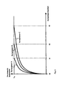
- Fig. 2 a diagram is shown which shows the basis of a simulation determined temperature of the pressure valve 20 of three compressors 13 different class according to the above table as a function of the running time of the respective compressor 13.
- the upper temperature limit of the pressure valve 20, at which the respective compressor 13 is turned off to avoid damage, is indicated in the diagram by To and represented by a horizontal line.
- the diagram shows that the temperature of the three compressors 13 increases from an instant t0 to an exponential function.
- the temperature of the pressure valve 20 of the assigned to Class 1 compressor A reaches because of its high efficiency, the upper temperature limit at time t1. After reaching the time t1, the compressor A must be turned off to avoid damage.
- the temperature of the pressure valve 20 of the class 2 allocated compressor B reaches the upper temperature limit at time t2. After reaching the time t2, the compressor B must be turned off to avoid damage.
- the temperature of the pressure valve 20 of the assigned to Class 3 compressor C reaches because of its low efficiency, the upper temperature limit until time t3. After reaching the time t3, the compressor C must be turned off to avoid damage.
- the invention enables the operation of the compressor A until the time t1, the operation of the compressor B until the time t2 and the operation of the compressor C until the time t3. Without the classification or the consideration of the efficiency of the respective compressor 13 in the determination of the temperature of the operation of the compressors A, B and C is possible only until the time t1, as to avoid damage always starting from a compressor 13 with a high efficiency is.
- the invention therefore allows a very good utilization of the compressors A, B and C, regardless of their efficiency.
- the determination of the temperature of the pressure valve 20 of the compressor 13 depending on the assigned class can be done in various ways. So z. B. be stored in the control unit 12 characteristic fields, based on which the temperature is determined depending on the class, the characteristic curves from individual characteristics according to Fig. 2 which are valid for a certain ambient temperature, back pressure and operating voltage of the compressor 13 are composed. The characteristics can z. B. be determined by a simulation or experimentally.
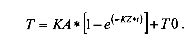
- this formula may also include other parameters such as ambient temperature, backpressure and operating voltage of the compressor 13.
- T designates the temperature of the pressure valve 20, KA and KZ to be determined by the class-dependent constants, t the time since a switch-on time of the compressor 13 and T0 the temperature prevailing at the switch-on time of the compressor 13 at the pressure valve 20.
- the constants KA and KZ can z. B. be determined experimentally.
- the temperature T0 can z. Example, be measured with a temperature sensor ambient temperature of the compressor 13, in the event that the compressor 13 was not operated for a long period of time and thus the compressor has the ambient temperature.
- T0 can also be z. B. on the basis of the temperature of the pressure valve 20 to the switching-off of the compressor 13 of a previous shutdown of the compressor 13 can be determined.
Landscapes
- Engineering & Computer Science (AREA)
- Mechanical Engineering (AREA)
- General Engineering & Computer Science (AREA)
- Computer Hardware Design (AREA)
- Control Of Positive-Displacement Pumps (AREA)
- Control Of Positive-Displacement Air Blowers (AREA)
Abstract
Description
- Die Erfindung betrifft ein Verfahren zur Steuerung eines Kompressors gemäß dem Oberbegriff des Patentanspruchs 1. Des Weiteren betrifft die Erfindung eine Vorrichtung zur Durchführung des Verfahrens.
- Beim Betrieb eines Kompressors ist darauf zu achten, dass bestimmte Temperaturgrenzen nicht überschritten werden, um Schäden zu vermeiden. Zur Vermeidung von Schäden wird der Kompressor bei dem Erreichen einer oberen Temperaturgrenze abgeschaltet. Beschädigungen des Kompressors infolge von Überhitzung können z.B. am Druckventil auftreten, etwa infolge einer Materialversprödung und einer sich hieraus ergebenden Oberflächenbeschädigung, die zu Undichtigkeiten am Ventil führt. Des Weiteren kann der Kolbenring Schaden nehmen, was zur Zerstörung des Kolbenrings und infolgedessen zu einem Ausfall des Kompressors führen kann.
- Eine Möglichkeit zur Einhaltung von Temperaturgrenzen stellt eine Überwachung von kritischen Bauteilen des Kompressors mittels Temperatursensoren dar. Aufgrund der benötigten Temperatursensoren ist diese Möglichkeit jedoch kostenaufwendig.
- Eine andere Möglichkeit stellt eine Berechnung von kritischen Temperaturen mittels einer Simulation oder eines Modells dar. So können z. B. in Abhängigkeit von Umgebungstemperatur, Gegendruck, gegen den der Kompressor arbeiten muss, und Betriebsspannung des Kompressors die Temperaturen von Bauteilen des Kompressors berechnet werden. Aus der
DE 196 21 946 C1 ist eine Steueranordnung für einen Kompressor bekannt, bei der aufgrund von Erfahrungswerten ein Schätzwert für die Betriebstemperatur des Kompressors ermittelt wird. Bei Überschreiten eines vorgegebenen Temperaturschwellenwertes kann der Kompressor dann automatisch abgeschaltet werden. Des Weiteren ist aus derDE 198 12 234 C2 bekannt, die Wärmeübertragungsbedingungen in der Umgebung des Kompressors abzuschätzen, z. B. anhand einer entsprechenden Modellbetrachtung, und in Abhängigkeit dieser Schätzdaten den Kompressor dann zu steuern. Derartige Verfahren können kostengünstig realisiert werden, da keine Temperatursensoren benötigt werden. - Dafür können bei diesen Verfahren die realen Temperaturbedingungen an dem Kompressor nur angenähert, d. h. durch Schätzwerte, berücksichtigt werden. Die Abweichungen zwischen den realen und berechneten Temperaturen haben jedoch eine relativ ineffiziente Ausnutzung des Kompressors zur Folge, da der Kompressor zur sicheren Vermeidung einer Beschädigung abgeschaltet wird, obwohl die obere Temperaturgrenze noch gar nicht erreicht ist.
- Der Erfindung liegt daher die Aufgabe zugrunde, ein Verfahren zur Steuerung eines Kompressors und eine Vorrichtung zur Durchführung des Verfahrens zur Verfügung zu stellen, welche eine effiziente Ausnutzung eines Kompressors ermöglichen.
- Diese Aufgabe wird gelöst durch ein Verfahren zur Steuerung eines Kompressors, wobei der Kompressor in Abhängigkeit eines Wirkungsgrades des Kompressors abgeschaltet werden kann. Unter einem Wirkungsgrad des Kompressors ist z. B. der von dem Kompressor erzeugte Volumenstrom zu verstehen. So erzeugt ein Kompressor mit einem hohen Wirkungsgrad einen hohen Volumenstrom und ein Kompressor mit einem niedrigen Wirkungsgrad einen niedrigen Volumenstrom. Ein Wirkungsgrad des Kompressors im Rahmen der Erfindung kann aber auch andere dem Fachmann geläufige Wirkungsgrade von Kompressoren umfassen. Bedingt durch unvermeidbare Produktionstoleranzen weisen Kompressoren gleichen Typs unterschiedliche Wirkungsgrade auf.
- Die Erfindung nutzt die Erkenntnis aus, dass die Erwärmung des Kompressors abhängig von einem Wirkungsgrad des Kompressors ist. So erwärmt sich z. B. ein Druckventil eines Kompressors mit einem hohen Wirkungsgrad, d. h. z. B. von einem Kompressor, der einen hohen Volumenstrom erzeugt, schneller, im Vergleich zu einem Kompressor mit einem geringeren Wirkungsgrad. Durch die mit der Erfindung durchgeführte Anpassung der Abschaltung des Kompressors an den jeweiligen Wirkungsgrad des Kompressors, können Kompressoren mit einem geringen Wirkungsgrad, d. h. z. B. mit einem geringen erzeugten Volumenstrom, ohne Überhitzung länger betrieben werden, als Kompressoren mit einem hohen Wirkungsgrad. Durch den längeren Betrieb erzeugt ein Kompressor mit einem geringen Wirkungsgrad für einen bestimmten Beobachtungszeitraum das gleiche Volumen an Druckluft wie ein Kompressor mit hohem Wirkungsgrad. Durch die unterschiedliche Betriebsdauer werden somit die Leistungsunterschiede zwischen Systemen, die Kompressoren unterschiedlichen Wirkungsgrades beinhalten, minimiert.
- Des Weiteren wird die o. g. Aufgabe gelöst durch ein Verfahren zur Steuerung eines Kompressors, wobei mit Hilfe einer Simulation oder eines Modells eine Größe ermittelt wird und der Kompressor in Abhängigkeit von der ermittelten Größe abgeschaltet werden kann, wobei die Größe in Abhängigkeit des Wirkungsgrades des Kompressors ermittelt wird. Unter einem Wirkungsgrad des Kompressors ist z. B. der von dem Kompressor erzeugte Volumenstrom zu verstehen. So erzeugt ein Kompressor mit einem hohen Wirkungsgrad einen hohen Volumenstrom und ein Kompressor mit einem niedrigen Wirkungsgrad einen niedrigen Volumenstrom. Ein Wirkungsgrad des Kompressors im Rahmen der Erfindung kann aber auch andere dem Fachmann geläufige Wirkungsgrade von Kompressoren umfassen.
- Unter der ermittelten Größe ist z. B. die Temperatur des Kompressors oder eines Bauteils des Kompressors zu verstehen. Die Erfindung nutzt die Erkenntnis aus, dass die Erwärmung des Kompressors abhängig von seinem Wirkungsgrad ist. So erwärmt sich z. B. ein Druckventil eines Kompressors mit einem hohen Wirkungsgrad, d. h. z. B. von einem Kompressor, der einen hohen Volumenstrom erzeugt, schneller, im Vergleich zu einem Kompressor mit einem geringeren Wirkungsgrad. Durch die Berücksichtigung des Wirkungsgrades des Kompressors bei der Ermittlung der Temperatur wird die Übereinstimmung zwischen der ermittelten Temperatur und der realen Temperatur im Vergleich zu den aus dem Stand der Technik bekannten Verfahren verbessert. Hierdurch resultiert eine bessere Ausnutzung des Kompressors, da bei den aus dem Stand der Technik bekannten Verfahren zur sicheren Einhaltung der Temperaturgrenzen bei der Ermittlung der Temperatur immer von einem Kompressor mit einem hohen Wirkungsgrad ausgegangen wird.
- Durch die mit der Erfindung durchgeführte Anpassung der Temperaturüberwachung an den jeweiligen Wirkungsgrad des Kompressors können Kompressoren mit einem geringen Wirkungsgrad, d. h. z. B. mit einem geringen erzeugten Volumenstrom, ohne Überhitzung länger betrieben werden, als Kompressoren mit einem hohen Wirkungsgrad. Durch den längeren Betrieb erzeugt ein Kompressor mit einem geringen Wirkungsgrad für einen bestimmten Beobachtungszeitraum das gleiche Volumen an Druckluft wie ein Kompressor mit hohem Wirkungsgrad. Durch die unterschiedliche Betriebsdauer werden somit die Leistungsunterschiede zwischen Systemen, die Kompressoren unterschiedlichen Wirkungsgrades beinhalten, minimiert. Es ist anzumerken, dass für die Ermittlung der Temperatur neben dem Wirkungsgrad des Kompressors weitere Parameter, wie z. B. Umgebungstemperatur, Gegendruck und Betriebsspannung des Kompressors, berücksichtigt werden können. Die Erfindung ermöglicht, trotz des Verzichts auf Temperatursensoren, eine sehr gute Übereinstimmung zwischen realer und durch Simulation oder Modell ermittelter Temperatur.
- Unter der Ermittlung der Temperatur mit Hilfe einer Simulation oder eines Modells im Sinne dieser Anmeldung ist zu verstehen, dass die Temperatur nicht ausschließlich anhand eines Temperatursensors ermittelt wird. Die Ermittlung der Temperatur mit Hilfe einer Simulation oder eines Modells umfasst auch die Ermittlung der Temperatur anhand von Kennlinien oder Kennlinienfeldern oder mathematischer Formeln. Sie kann weiterhin die Ermittlung einer Temperatur unter Einbeziehung der Signale eines Temperatursensors umfassen. So ist es denkbar, dass z. B. die Temperatur der den Kompressor umgebenden Luft mit einem Temperatursensor erfasst wird und anhand der Signale des Temperatursensors mit Hilfe des erfindungsgemäßen Verfahrens die Temperatur eines Druckventils des Kompressors ermittelt wird.
- In einer vorteilhaften Ausgestaltung der Erfindung wird der Kompressor in Abhängigkeit seines Wirkungsgrades einer Klasse zugeteilt und die Temperatur in Abhängigkeit der zugeteilten Klasse ermittelt. Diese Ausgestaltung ermöglicht eine besonders effiziente Ermittlung der Temperatur.
- In einer weiteren vorteilhaften Ausgestaltung der Erfindung kann die Abschaltung in Abhängigkeit der ermittelten Temperatur eines in dem Kompressor vorhandenen Druckventils und/oder in Abhängigkeit einer ermittelten Temperatur eines in dem Kompressor vorhandenen Kolbenrings und/oder in Abhängigkeit einer ermittelten Temperatur eines den Kompressor antreibenden Elektromotors erfolgen. Da oftmals das Druckventil oder der Kolbenring oder der den Kompressor antreibenden Elektromotor die am stärksten temperaturbeanspruchten Bauteile des Kompressors darstellen, wird der Kompressor durch diese Ausgestaltung zuverlässig gegen die Überschreitung einer Temperaturgrenze geschützt.
- Gemäß einer weiteren Ausführung wird der Wirkungsgrad des Kompressors mittels einer Zeitspanne bestimmt, die der Kompressor für einen Anstieg eines Druckes in einem Druckspeicher, der von dem Kompressor mit Druckmittel versorgt wird, um einen festgelegten Wert benötigt. Diese Ausführung ermöglicht eine einfache und genaue Bestimmung des Wirkungsgrades.
- Entsprechend einer weiteren Ausgestaltung erfolgt die Bestimmung des Wirkungsgrades automatisch. Der Aufwand zur Bestimmung des Wirkungsgrades wird hierdurch reduziert. Die Bestimmung kann z. B. mit Hilfe eines den Kompressor steuernden Steuergerätes erfolgen.
- Vorteilhafterweise kann die Zeitspanne in Abhängigkeit einer Betriebsspannung des Kompressors und/oder eines Druckes der den Kompressor umgebenden Luft korrigiert werden. Hierdurch wird eine von der Betriebsspannung des Kompressors und des Druckes der den Kompressor umgebenden Luft unabhängige Bestimmung des Wirkungsgrades gewährleistet.
- Vorteilhaft ist auch eine Ausgestaltung, bei der eine Bestimmung des Wirkungsgrades des Kompressors und/oder eine Klassifizierung des Kompressors (Zuteilung der Klasse) bei einer Inbetriebnahme eines Systems, in dem der Kompressor verbaut ist, durchgeführt wird. Diese Ausgestaltung vermeidet die Bestimmung des Wirkungsgrades und/oder die Klassifizierung im Rahmen der Produktion des Kompressors. Somit wird der Aufwand für die Produktion vermindert. Das System kann z. B. ein Luftfedersystem für Fahrzeuge sein.
- In einer weiteren vorteilhaften Ausgestaltung der Erfindung erfolgt im Rahmen einer Inspektion des Systems eine erneute Bestimmung des Wirkungsgrades des Kompressors und/oder eine erneute Klassifizierung des Kompressors. Hierdurch werden alterungsbedingte Veränderungen des Kompressors bei der Bestimmung des Wirkungsgrades des Kompressors und/oder der Klassifizierung des Kompressors berücksichtigt.
- In einer weiteren vorteilhaften Ausführung erfolgt eine regelmäßige Bestimmung des Wirkungsgrades des Kompressors und/oder eine regelmäßige Klassifizierung des Kompressors. Unter regelmäßig sind z. B. die Durchführung einer Bestimmung des Wirkungsgrades des Kompressors und/oder einer Klassifizierung des Kompressors bei jeder Inbetriebnahme des Systems oder in bestimmten Zeitintervallen zu verstehen. Hierdurch wird das Ergebnis der Bestimmung des Wirkungsgrades des Kompressors und/oder der Klassifizierung des Kompressors verbessert.
- Vorteilhaft ist eine Ausführung, bei der eine Änderung der Klasse nur erfolgt, falls eine bestimmte Anzahl von aufeinander folgenden Klassifizierungen mit dem gleichen Ergebnis erreicht wird. Hierdurch wird der Einfluss von zufälligen Fehlern auf das Ergebnis der Klassifizierung minimiert.
- Bei dieser Ausführung ist es vorteilhaft, wenn die benötigte Anzahl für eine Erhöhung der Klasse kleiner als die für eine Verringerung der Klasse ist. Hierdurch wird der Schutz des Kompressors gegen unzulässig hohe Temperaturen verbessert. Unter einer Erhöhung der Klasse ist zu verstehen, dass der Kompressor einer Klasse mit höherem Wirkungsgrad zugeteilt wird. Unter einer Verringerung der Klasse ist zu verstehen, dass der Kompressor einer Klasse mit geringerem Wirkungsgrad zugeteilt wird.
- In einer weiteren vorteilhaften Ausgestaltung erfolgt die Klassifizierung in Abhängigkeit eines Volumens des Druckspeichers und des Kompressortyps. So kann die Anzahl der Klassen und/oder die Zeitspanne an das Volumen des Druckspeichers und die Typenklasse, bzw. die Nennleistung des Kompressors angepasst werden.
- Eine weitere Ausführung zeichnet sich durch einen Einsatz des Kompressors in einem Fahrzeug aus.
- Bei einer weiteren Ausführung wird der Kompressor in einem Luftfedersystem eingesetzt.
- Bei einer weiteren Ausgestaltung wird die Temperatur anhand der Formel

- Ermittelt, wobei T die zu ermittelnde Temperatur des Druckventils, KA und KZ von der Klasse abhängige Konstanten, t die Zeit seit einem Einschaltzeitpunkt des Kompressors und T0 die am Einschaltzeitpunkt des Kompressors herrschende Temperatur bezeichnen.
- Weiterhin beinhaltet die Erfindung eine Vorrichtung zur Steuerung eines Kompressors, wobei Mittel den Kompressor in Abhängigkeit eines Wirkungsgrades des Kompressors abschalten.
- Des Weiteren beinhaltet die Erfindung eine Vorrichtung zur Steuerung eines Kompressors, wobei mit Hilfe einer Simulation oder eines Modells eine Grö-ße ermittelbar ist und der Kompressor in Abhängigkeit von der ermittelten Größe abschaltbar ist, wobei Mittel die Größe in Abhängigkeit des Wirkungsgrades des Kompressors ermitteln.
- Ausführungsbeispiele der Erfindung werden im Folgenden anhand der schematischen Zeichnung erläutert. Es zeigen:
- Fig. 1
- eine schematische Darstellung einer Druckmittelanlage für eine pneumatische Fahrzeugfederung und
- Fig. 2
- ein Diagramm, welches Laufzeiten von Kompressoren unterschiedlicher Klassen veranschaulicht.
- In
Fig. 1 ist ein System gezeigt, in dem ein Kompressor 13 verbaut ist. Es handelt sich dabei um eine Luftfederungsanlage für ein Fahrzeug, die vier Luftfederbälge 1, 2, 3, 4 umfasst, die jeweils ein Rad eines vierrädrigen Fahrzeugs abfedern. Die Luftfederbälge 1, 2, 3, 4 sind über pneumatische Leitungen mit 2/2-Wegeventilen 6, 7, 9, 10 verbunden. Des Weiteren ist ein Druckspeicher 5 vorgesehen, der über eine pneumatische Leitung mit einem weiteren 2/2-Wegeventil 8 verbunden ist. Zur Sensierung des Drucks in dem Druckspeicher 5 ist ein Drucksensor 11 mit dem Druckspeicher 5 verbunden. - Die Ventile 6, 7, 8, 9, 10 sind druckmittelseitig über weitere pneumatische Leitungen gemeinsam an einen Lufttrockner 14 mit Regenerationsfunktion angeschlossen. Der Lufttrockner 14 weist eine Regenerationsfunktion bekannter Art auf, bei der Druckluft aus den Luftfederbälgen 1, 2, 3, 4 oder dem Druckspeicher 5 über die Ventile 6, 7, 8, 9, 10 in den Lufttrockner 14 zurückströmt und über einen Regenerationspfad in die Atmosphäre abgelassen werden kann, wobei Feuchtigkeit abgeführt wird.
- Der Lufttrockner 14 ist druckmittelseitig mit dem Kompressor 13, z. B. einem Kolbenkompressor üblicher Bauart, verbunden. Der über eine Welle von einem Elektromotor 15 antreibbare Kompressor 13 saugt über einen Ansauganschluss 17 Luft aus der Atmosphäre an. Durch Einschalten des Elektromotors 15 kann komprimierte Luft erzeugt und an die die Druckmittelanlage 1, 2, 3, 4, 5, 6, 7, 8, 9, 10, 14 darstellende Luftfederungsanlage abgegeben werden.
- Die Ventile 6, 7, 8, 9 10 sind als elektromagnetisch betätigbare Ventile ausgebildet und mit ihren elektrischen Anschlüssen einerseits mit der elektrischen Masse verbunden, andererseits mit einem elektronischen Steuergerät 12, das zur Steuerung der nachfolgend noch näher beschriebenen Funktionen dient. Des Weiteren ist der Lufttrockner 14 zwecks Aktivierung der Regenerationsfunktion über eine elektrische Leitung mit dem Steuergerät 12 verbunden. Außerdem ist der Elektromotor 15 zur Aktivierung über eine elektrische Leitung mit dem Steuergerät 12 verbunden.
- Der Drucksensor 11 ist über weitere elektrische Leitungen mit dem Steuergerät 12 verbunden. Des Weiteren ist mit dem Steuergerät 12 ein z. B. von dem Fahrer des mit der Luftfederungsanlage ausgestatteten Fahrzeuges zu bedienendes Bedienelement 18 verbunden, mit dem die Einstellung verschiedener Fahrzeugniveaus, z.B. eines oberen, eines mittleren und eines unteren Niveaus, möglich ist. Das jeweilige Fahrzeugniveau bzw. die jeweilige Niveaulage an den einzelnen Federbeinen des Fahrzeugs wird über geeignete Wegsensoren gemessen, die in der
Fig. 1 der Einfachheit halber nicht dargestellt sind. Diese Wegsensoren bekannter Bauart sind ebenfalls mit dem Steuergerät 12 verbunden. - Das Steuergerät 12 verarbeitet diese Eingangssignale des Drucksensors 11, des Bedienelements 18 und der Wegsensoren und erzeugt hieraus Ansteuersignale für den Elektromotor 15, den Lufttrockner 14 sowie die Ventile 6, 7, 8, 9, 10.
- Die Luftfederungsanlage gemäß
Fig. 1 arbeitet wie folgt: - Wenn das Steuergerät 12 an einem oder mehreren Federbeinen eine Abweichung zwischen der durch den jeweiligen Wegsensor gemessenen Niveaulage und einer Soll-Niveaulage, die aufgrund des Bedienelements 18 bestimmt wird, feststellt, so steuert es das dem Federbein zugeordnete Magnetventil 6, 7, 9, 10 an, wodurch das Ventil von seiner Sperrstellung in einer Durchlassstellung geschaltet wird. Sofern die Niveaulage erhöht werden soll und somit die Luftmasse in dem Luftfederbalg 1, 2, 3, 4 erhöht werden muss, steuert das elektronische Steuergerät 12 zusätzlich das Magnetventil 8 an, wodurch Druckmittel von dem Druckspeicher 5 in den jeweiligen Luftfederbalg 1, 2, 3, 4 strömen kann. Je nach gewünschtem Druck in dem Luftfederbalg 1, 2, 3, 4 und vorhandenem Druck in dem Druckspeicher 5 schaltet das Steuergerät 12 gegebenenfalls zusätzlich den Elektromotor 15 ein, wodurch der Kompressor 13 in Betrieb gesetzt wird und ein höheres Druckniveau erzeugt werden kann als in dem Druckspeicher 5 noch vorliegt.
- Es ist erkennbar, dass bei häufigem Niveauwechsel, z. B. infolge häufiger Betätigung des Bedienelements 18, der Druckluftvorrat in dem Druckspeicher 5 aufgebraucht wird und somit Druckluft durch den Kompressor 13 nachgefördert werden muss. Üblicherweise ist der Druckspeicher 5 für ein- bis zweimaliges vollständiges Absenken und Anheben des Fahrzeugs dimensioniert.
- Falls eine Verminderung der Luftmasse in einem Luftfederbalg 1, 2, 3, 4 notwendig ist, so bleibt das Ventil 8 geschlossen und der Kompressor 13 ausgeschaltet. Des Weiteren wird der Lufttrockner 14 in die Regenerationsstellung umgeschaltet, wodurch Druckluft aus dem zu entlüftenden Luftfederbalg 1, 2, 3, 4 in die Atmosphäre strömen kann. Hierbei wird au-ßerdem unerwünschte Feuchtigkeit abgeschieden.
- Der Druckspeicher 5 dient dazu, wie zuvor schon angedeutet, eine schnelle Erhöhung der Luftmasse in den Luftfederbälgen 1, 2, 3, 4 und somit ein schnelles Anheben der Niveaulage zu ermöglichen. Wegen der vergleichsweise geringen Fördermenge des Kompressors 13 kann dieser nur langsamer eine Luftmassenerhöhung in den Luftfederbälgen 1, 2, 3, 4 bewirken. Daher ist es zweckmäßig, dass der Druckspeicher 5 ständig auf einem ausreichenden Druckniveau gehalten wird bzw. bei einem Druckabfall das gewünschte ausreichende Druckniveau möglichst schnell wieder hergestellt wird. Zusätzlich soll aber der Kompressor 13 hierbei nicht überlastet werden und nach Möglichkeit auch für eine angeforderte Niveauerhöhung zur Verfügung stehen. Um eine Überlastung des Kompressors 13 zu vermeiden, wird die Temperatur eines in dem Kompressor 13 vorhandenen Druckventils 20 anhand einer Simulation ermittelt. Die Simulation wird in dem Steuergerät 12 anhand dort hinterlegter physikalischer Modelle des Kompressors 13 und der Umgebungsbedingungen durchgeführt.
- Die Erfindung sieht vor, dass in vorteilhafter Weise die Temperatur des Druckventils 20 in Abhängigkeit des Wirkungsgrads des Kompressors 13, d. h. in Abhängigkeit des von dem Kompressor erzeugten Volumenstroms, ermittelt wird. Neben dem Wirkungsgrad können auch andere Parameter, wie Umgebungstemperatur, Gegendruck, gegen den der Kompressor 13 arbeiten muss, und Betriebsspannung des Kompressors 13, bei der Ermittlung der Temperatur berücksichtigt werden.
- Die Bestimmung des Wirkungsgrades geschieht folgendermaßen:
- Bei einer Inbetriebnahme der Luftfederungsanlage werden die Ventile 6, 7, 9, 10 in Sperrstellung geschaltet. Das Ventil 8 wird dagegen in Durchlassstellung geschaltet. Die Luftfederbälge 1, 2, 3, 4 sind somit vom Kompressor 13 entkoppelt, wogegen der Kompressor 13 über den Lufttrockner 14 mit dem Druckspeicher 5 verbunden ist. Nun wird der in dem Druckspeicher 5 herrschende Druck durch den Drucksensor 11 erfasst. Anschließend wird durch Einschalten des Elektromotors 15 der Kompressor 13 aktiviert, um den Druck in dem Druckspeicher 5 zu erhöhen. Der Druck in dem Druckspeicher 5 wird solange durch einen nicht durch Pausen unterbrochenen Betrieb des Kompressors 13 erhöht, bis ein vorgegebener Wert, z. B. 2 bar, für den Druckanstieg erreicht ist. Nun wird die Zeitspanne bestimmt, die der Kompressor 13 für den Druckanstieg in dem Druckspeicher 5 benötigt hat. Diese Zeitspanne ist ein Maß für den Wirkungsgrad des Kompressors 13 und des von dem Kompressor 13 erzeugten Volumenstromes. Die Steuerung der Elemente der Luftfederungsanlage und die Bestimmung des Wirkungsgrades erfolgt mit Hilfe des Steuergerätes 12. Unter einer Inbetriebnahme der Luftfederungsanlage ist z. B. die Erstinbetriebnahme der Luftfederungsanlage oder eine Inbetriebnahme nach dem Aktivieren einer Zündung eines Fahrzeugs, in welchem die Luftfederungsanlage verbaut ist, zu verstehen.
- Die Erfindung sieht vor, den Kompressor 13 in Abhängigkeit des Wirkungsgrades abzuschalten. Die Abschaltung des Kompressors 13 erfolgt durch das Steuergerät 12. Der Wirkungsgrad kann in einem Speicher des Steuergerätes 12 gespeichert werden.
- Des Weiteren sieht die Erfindung vor, mittels einer Simulation oder eines Modells eine Temperatur zu ermitteln und den Kompressor 13 in Abhängigkeit der Temperatur abzuschalten, wobei die Temperatur in Anhängigkeit des Wirkungsgrades des Kompressors 13 ermittelt wird. Die Ermittlung der Temperatur und die Abschaltung des Kompressors 13 erfolgt mittels des Steuergerätes 12.
- Gemäß einer vorteilhaften Ausgestaltung wird der Kompressor 13 in Abhängigkeit seines Wirkungsgrades und somit in Abhängigkeit des von ihm erzeugten Volumenstromes einer Klasse zugeteilt.
- Gemäß einer vorteilhaften Ausführung kann die Zeitspanne in Abhängigkeit der Betriebsspannung des Kompressors 13 und/oder des Druckes der den Kompressor 13 umgebenden Luft korrigiert werden. So kann beispielsweise die bestimmte (gemessene) Zeitspanne mit einem Faktor aus dem Verhältnis zwischen einer Referenz-Betriebsspannung und der gemessenen Betriebsspannung multipliziert werden, um die korrigierte Zeitspanne zu erhalten. Analog kann z. B. die Korrektur der Zeitspanne in Abhängigkeit des Druckes der den Kompressor 13 umgebenden Luft erfolgen. Des Weiteren kann die Klassifizierung regelmäßig, z. B. bei jeder Inbetriebnahme der Luftfederungsanlage, erfolgen, um eine genauere Klassifizierung zu ermöglichen oder Einflüsse von Alterung auf das Verhalten des Kompressors 13 zu berücksichtigen.
- In folgender Tabelle ist eine Vorschrift für die Klassifizierung von Kompressoren 13 dargestellt.
Zeitspanne < tk1 ≥ tk1 und ≤ tk3 > tk3 Klasse 1 2 3 Kompressor A B C - Kompressoren 13, die für den Anstieg des Drucks in dem Druckspeicher 5 um einen festgelegten Wert eine Zeitspanne benötigen, die unterhalb tk1 liegt, werden der Klasse 1 zugeteilt. In diesem Fall der Kompressor A. Kompressoren 13, deren Zeitspanne größer gleich tk1 und kleiner gleich tk3 beträgt, werden der Klasse 2 zugeteilt. In diesem Fall der Kompressor B. Kompressoren 13, die eine Zeitspanne größer tk3 benötigen, werden der Klasse 3 zugeteilt. In diesem Fall der Kompressor C. Es gilt tk1 kleiner tk3. Hieraus folgt, dass der Wirkungsgrad der Kompressoren 13, also der von dem jeweiligen Kompressor 13 erzeugte Volumenstrom, mit steigender Klasse abnimmt. In diesem Fall existieren drei Klassen 1, 2 und 3. Gemäß einer vorteilhaften Ausführung kann die Vorschrift zur Klassifizierung an das Volumen des Druckspeichers 5 und an den Kompressortyp angepasst werden. So können die Anzahl der Klassen und/oder die Zeitspanne an das Volumen des Druckspeichers 5 und der Typenklasse, bzw. der Nennleistung des Kompressors 13 angepasst werden. So kann z. B. die Anzahl der Klassen mit zunehmenden Volumen des Druckspeichers 5 und/oder zunehmender Nennleistung des Kompressors 13 ansteigen.
- In
Fig. 2 ist ein Diagramm dargestellt, welches die anhand einer Simulation ermittelte Temperatur des Druckventils 20 dreier Kompressoren 13 unterschiedlicher Klasse gemäß der oben stehenden Tabelle in Abhängigkeit der Laufzeit des jeweiligen Kompressors 13 zeigt. Die obere Temperaturgrenze des Druckventils 20, bei der der jeweilige Kompressor 13 abzuschalten ist, um Schäden zu vermeiden, ist in dem Diagramm mit To bezeichnet und durch eine horizontale Linie dargestellt. Dem Diagramm ist zu entnehmen, dass die Temperatur der drei Kompressoren 13 jeweils ausgehend vom Zeitpunkt t0 nach einer Exponentialfunktion ansteigt. - Die Temperatur des Druckventils 20 des der Klasse 1 zugeteilten Kompressors A erreicht wegen seines hohen Wirkungsgrades die obere Temperaturgrenze schon zum Zeitpunkt t1. Nach dem Erreichen des Zeitpunktes t1 muss der Kompressor A abgeschaltet werden, um Schäden zu vermeiden.
- Die Temperatur des Druckventils 20 des der Klasse 2 zugeteilten Kompressors B erreicht die obere Temperaturgrenze zum Zeitpunkt t2. Nach dem Erreichen des Zeitpunktes t2 muss der Kompressor B abgeschaltet werden, um Schäden zu vermeiden.
- Die Temperatur des Druckventils 20 des der Klasse 3 zugeteilten Kompressors C erreicht wegen seines geringen Wirkungsgrades die obere Temperaturgrenze erst zum Zeitpunkt t3. Nach dem Erreichen des Zeitpunktes t3 muss der Kompressor C abgeschaltet werden, um Schäden zu vermeiden.
- Durch die Klassifizierung der Kompressoren 13 und die Ermittlung der Temperatur in Abhängigkeit der zugeteilten Klasse ermöglicht die Erfindung den Betrieb des Kompressors A bis zum Zeitpunkt t1, den Betrieb des Kompressors B bis zum Zeitpunkt t2 und den Betrieb des Kompressors C bis zum Zeitpunkt t3. Ohne die Klassifizierung oder die Berücksichtigung des Wirkungsgrades des jeweiligen Kompressors 13 bei der Ermittlung der Temperatur ist der Betrieb der Kompressoren A, B und C nur bis zum Zeitpunkt t1 möglich, da zur sicheren Vermeidung einer Beschädigung immer von einem Kompressor 13 mit einem hohen Wirkungsgrad auszugehen ist. Die Erfindung ermöglicht daher eine sehr gute Ausnutzung der Kompressoren A, B und C, unabhängig von deren Wirkungsgrad.
- Die Ermittlung der Temperatur des Druckventils 20 des Kompressors 13 in Abhängigkeit der zugeteilten Klasse kann auf verschiedene Arten erfolgen. So können z. B. in dem Steuergerät 12 Kennlinienfelder hinterlegt sein, anhand derer die Temperatur in Abhängigkeit der Klasse ermittelt wird, wobei die Kennlinienfelder aus einzelnen Kennlinien gemäß
Fig. 2 , die für eine bestimmte Umgebungstemperatur, Gegendruck und Betriebsspannung des Kompressors 13 Gültigkeit haben, zusammengesetzt sind. Die Kennlinien können dabei z. B. durch eine Simulation oder auch experimentell ermittelt werden. - Es ist aber auch möglich die Temperatur in Abhängigkeit der Klasse durch eine mathematische Formel zu ermitteln. Neben der Klasse kann diese Formel auch andere Parameter, wie Umgebungstemperatur, Gegendruck und Betriebsspannung des Kompressors 13, umfassen.
- Ein Beispiel für die Ermittlung der Temperatur, z. B. des Druckventils 20, in Abhängigkeit der Klasse durch eine mathematische Formel stellt nachstehende Formel dar:
- In der Formel bezeichnen T die zu ermittelnde Temperatur des Druckventils 20, KA und KZ von der Klasse abhängige Konstanten, t die Zeit seit einem Einschaltzeitpunkt des Kompressors 13 und T0 die am Einschaltzeitpunkt des Kompressors 13 am Druckventil 20 herrschende Temperatur. Die Konstanten KA und KZ können z. B. experimentell ermittelt werden. Die Temperatur T0 kann z. B. die mit einem Temperatursensor gemessene Umgebungstemperatur des Kompressors 13 sein, für den Fall, dass der Kompressors 13 für einen längeren Zeitraum nicht betrieben wurde und somit der Kompressor die Umgebungstemperatur aufweist. T0 kann aber auch z. B. anhand der Temperatur des Druckventils 20 zum Abschaltzeitpunkt des Kompressors 13 eines vorherigen Abschaltvorgangs des Kompressors 13 ermittelt werden.
Claims (19)
- Verfahren zur Steuerung eines Kompressors (13), dadurch gekennzeichnet, dass der Kompressor (13) in Abhängigkeit eines Wirkungsgrades des Kompressors (13) abgeschaltet werden kann.
- Verfahren zur Steuerung eines Kompressors (13), wobei mit Hilfe einer Simulation oder eines Modells eine Größe ermittelt wird und der Kompressor (13) in Abhängigkeit von der ermittelten Größe abgeschaltet werden kann, dadurch gekennzeichnet, dass die Größe in Abhängigkeit eines Wirkungsgrades des Kompressors (13) ermittelt wird.
- Verfahren nach Anspruch 2, dadurch gekennzeichnet, dass die Größe eine Temperatur ist.
- Verfahren nach Anspruch 3, dadurch gekennzeichnet, dass der Kompressor (13) in Abhängigkeit seines Wirkungsgrades einer Klasse zugeteilt wird und die Temperatur in Abhängigkeit der zugeteilten Klasse ermittelt wird.
- Verfahren nach einem der vorherigen Ansprüche 3 oder 4, dadurch gekennzeichnet, dass die Abschaltung in Abhängigkeit einer ermittelten Temperatur eines in dem Kompressor (13) vorhandenen Druckventils (20) und/oder in Abhängigkeit einer ermittelten Temperatur eines in dem Kompressor (13) vorhandenen Kolbenrings und/oder in Abhängigkeit einer ermittelten Temperatur eines den Kompressor (13) antreibenden Elektromotors (15) erfolgen kann.
- Verfahren nach einem der vorherigen Ansprüche, dadurch gekennzeichnet, dass der Wirkungsgrad des Kompressors (13) mittels einer Zeitspanne bestimmt wird, die der Kompressor (13) für einen Anstieg eines Druckes in einem Druckspeicher (5), der von dem Kompressor (13) mit Druckmittel versorgt wird, um einen festgelegten Wert benötigt.
- Verfahren nach Anspruch 6, dadurch gekennzeichnet, dass die Bestimmung des Wirkungsgrades automatisch erfolgt.
- Verfahren nach Anspruch 6 oder 7, dadurch gekennzeichnet, dass die Zeitspanne in Abhängigkeit einer Betriebsspannung des Kompressors (13) und/oder eines Druckes der den Kompressor (13) umgebenden Luft korrigiert wird.
- Verfahren nach einem der vorherigen Ansprüche, dadurch gekennzeichnet, dass eine Bestimmung des Wirkungsgrades des Kompressors (13) und/oder eine Klassifizierung des Kompressors (13) bei einer Inbetriebnahme eines Systems, in dem der Kompressor (13) verbaut ist, durchgeführt wird.
- Verfahren nach einem der vorherigen Ansprüche, dadurch gekennzeichnet, dass im Rahmen einer Inspektion des Systems eine erneute Bestimmung des Wirkungsgrades des Kompressors (13) und/oder eine erneute Klassifizierung des Kompressors (13) erfolgt.
- Verfahren nach einem der vorherigen Ansprüche, dadurch gekennzeichnet, dass eine regelmäßige Bestimmung des Wirkungsgrades des Kompressors (13) und/oder eine regelmäßige Klassifizierung des Kompressors (13) erfolgt.
- Verfahren nach Anspruch 11, dadurch gekennzeichnet, dass eine Änderung der Klasse nur erfolgt, falls eine bestimmte Anzahl von aufeinander folgenden Klassifizierungen mit dem gleichen Ergebnis erreicht wird.
- Verfahren nach Anspruch 12, dadurch gekennzeichnet, dass die benötigte Anzahl für eine Erhöhung der Klasse kleiner als die für eine Verringerung der Klasse ist.
- Verfahren nach einem der vorherigen Ansprüche 4 bis 13, dadurch gekennzeichnet, dass die Klassifizierung in Abhängigkeit eines Volumen des Druckspeichers (5) und des Kompressortyps erfolgt.
- Verfahren nach einem der vorherigen Ansprüche, dadurch gekennzeichnet, dass der Kompressor (13) in einem Fahrzeug eingesetzt wird.
- Verfahren nach einem der vorherigen Ansprüche, dadurch gekennzeichnet, dass der Kompressor (13) in einem Luftfedersystem eingesetzt wird.
- Verfahren nach einem der vorherigen Ansprüche 3 bis 16, dadurch gekennzeichnet, dass die Temperatur anhand der Formel

- Vorrichtung zur Steuerung eines Kompressors (13), gekennzeichnet durch Mittel, die den Kompressor (13) in Abhängigkeit eines Wirkungsgrades des Kompressors (13) abschalten.
- Vorrichtung zur Steuerung eines Kompressors (13), wobei mit Hilfe einer Simulation oder eines Modells eine Größe ermittelbar ist und der Kompressor (13) in Abhängigkeit von der ermittelten Größe abschaltbar ist, gekennzeichnet durch Mittel, welche die Größe in Abhängigkeit des Wirkungsgrades des Kompressors (13) ermitteln.
Applications Claiming Priority (1)
| Application Number | Priority Date | Filing Date | Title |
|---|---|---|---|
| DE102007008736A DE102007008736A1 (de) | 2007-02-22 | 2007-02-22 | Verfahren zur Steuerung eines Kompressors und Vorrichtung zur Durchführung des Verfahrens |
Publications (3)
| Publication Number | Publication Date |
|---|---|
| EP1961960A2 true EP1961960A2 (de) | 2008-08-27 |
| EP1961960A3 EP1961960A3 (de) | 2010-01-20 |
| EP1961960B1 EP1961960B1 (de) | 2017-04-12 |
Family
ID=39431000
Family Applications (1)
| Application Number | Title | Priority Date | Filing Date |
|---|---|---|---|
| EP08002142.1A Active EP1961960B1 (de) | 2007-02-22 | 2008-02-06 | Verfahren zur Steuerung eines Kompressors und Vorrichtung zur Durchführung des Verfahrens |
Country Status (3)
| Country | Link |
|---|---|
| EP (1) | EP1961960B1 (de) |
| DE (1) | DE102007008736A1 (de) |
| PL (1) | PL1961960T3 (de) |
Cited By (7)
| Publication number | Priority date | Publication date | Assignee | Title |
|---|---|---|---|---|
| WO2011117341A1 (de) * | 2010-03-25 | 2011-09-29 | Continental Teves Ag & Co. Ohg | Verfahren zur regelung eines kompressors |
| WO2012000703A1 (de) * | 2010-06-30 | 2012-01-05 | Continental Teves Ag & Co. Ohg | Höhenabhängige kompressorsteuerung |
| FR2990158A1 (fr) * | 2012-05-03 | 2013-11-08 | Peugeot Citroen Automobiles Sa | Systeme de suspension hydropneumatique comportant une reserve additionnelle de pression et procede associe |
| EP2968709A4 (de) * | 2013-03-15 | 2017-08-09 | Levant Power Corporation | Verbesserungen an einer aktiven fahrzeugfederung |
| EP3516218B1 (de) | 2016-09-21 | 2021-03-17 | KNORR-BREMSE Systeme für Nutzfahrzeuge GmbH | Kompressorsystem für ein nutzfahrzeug |
| US11021033B2 (en) | 2013-03-15 | 2021-06-01 | ClearMotion, Inc. | Active vehicle suspension system |
| US11732706B2 (en) | 2019-09-27 | 2023-08-22 | Continental Teves Ag & Co. Ohg | Method for service life monitoring of a compressor for a compressed air system |
Families Citing this family (1)
| Publication number | Priority date | Publication date | Assignee | Title |
|---|---|---|---|---|
| DE102013111218A1 (de) * | 2013-10-10 | 2015-04-16 | Kaeser Kompressoren Se | Elektronische Steuerungseinrichtung für eine Komponente der Drucklufterzeugung, Druckluftaufbereitung, Druckluftspeicherung und/oder Druckluftverteilung |
Citations (2)
| Publication number | Priority date | Publication date | Assignee | Title |
|---|---|---|---|---|
| DE19621946C1 (de) | 1996-05-31 | 1997-09-18 | Daimler Benz Ag | Luftfederung |
| DE19812234C2 (de) | 1998-03-20 | 2002-07-18 | Daimler Chrysler Ag | Luftfederungsanlage für Fahrzeuge |
Family Cites Families (2)
| Publication number | Priority date | Publication date | Assignee | Title |
|---|---|---|---|---|
| DE2344850C3 (de) * | 1973-09-06 | 1978-04-27 | Klein, Schanzlin & Becker Ag, 6710 Frankenthal | Selbsttätige Steuerung fur ein Pumpwerk |
| US5546015A (en) * | 1994-10-20 | 1996-08-13 | Okabe; Toyohiko | Determining device and a method for determining a failure in a motor compressor system |
-
2007
- 2007-02-22 DE DE102007008736A patent/DE102007008736A1/de not_active Withdrawn
-
2008
- 2008-02-06 EP EP08002142.1A patent/EP1961960B1/de active Active
- 2008-02-06 PL PL08002142T patent/PL1961960T3/pl unknown
Patent Citations (2)
| Publication number | Priority date | Publication date | Assignee | Title |
|---|---|---|---|---|
| DE19621946C1 (de) | 1996-05-31 | 1997-09-18 | Daimler Benz Ag | Luftfederung |
| DE19812234C2 (de) | 1998-03-20 | 2002-07-18 | Daimler Chrysler Ag | Luftfederungsanlage für Fahrzeuge |
Cited By (14)
| Publication number | Priority date | Publication date | Assignee | Title |
|---|---|---|---|---|
| CN102822526B (zh) * | 2010-03-25 | 2014-12-24 | 大陆-特韦斯贸易合伙股份公司及两合公司 | 用于调节压缩机的方法 |
| US9243627B2 (en) | 2010-03-25 | 2016-01-26 | Continetal Teves Ag & Co. Ohg | Compressor temperature control by indirect temperature measurement |
| CN102822526A (zh) * | 2010-03-25 | 2012-12-12 | 大陆-特韦斯贸易合伙股份公司及两合公司 | 用于调节压缩机的方法 |
| WO2011117341A1 (de) * | 2010-03-25 | 2011-09-29 | Continental Teves Ag & Co. Ohg | Verfahren zur regelung eines kompressors |
| CN102958716A (zh) * | 2010-06-30 | 2013-03-06 | 大陆-特韦斯贸易合伙股份公司及两合公司 | 基于海拔高度的压缩机控制 |
| WO2012000703A1 (de) * | 2010-06-30 | 2012-01-05 | Continental Teves Ag & Co. Ohg | Höhenabhängige kompressorsteuerung |
| CN102958716B (zh) * | 2010-06-30 | 2016-09-28 | 大陆-特韦斯贸易合伙股份公司及两合公司 | 基于海拔高度的压缩机控制方法 |
| FR2990158A1 (fr) * | 2012-05-03 | 2013-11-08 | Peugeot Citroen Automobiles Sa | Systeme de suspension hydropneumatique comportant une reserve additionnelle de pression et procede associe |
| EP2968709A4 (de) * | 2013-03-15 | 2017-08-09 | Levant Power Corporation | Verbesserungen an einer aktiven fahrzeugfederung |
| US10828953B2 (en) | 2013-03-15 | 2020-11-10 | ClearMotion, Inc. | Self-driving vehicle with integrated active suspension |
| US11021033B2 (en) | 2013-03-15 | 2021-06-01 | ClearMotion, Inc. | Active vehicle suspension system |
| US11850905B2 (en) | 2013-03-15 | 2023-12-26 | ClearMotion, Inc. | Active vehicle suspension system |
| EP3516218B1 (de) | 2016-09-21 | 2021-03-17 | KNORR-BREMSE Systeme für Nutzfahrzeuge GmbH | Kompressorsystem für ein nutzfahrzeug |
| US11732706B2 (en) | 2019-09-27 | 2023-08-22 | Continental Teves Ag & Co. Ohg | Method for service life monitoring of a compressor for a compressed air system |
Also Published As
| Publication number | Publication date |
|---|---|
| EP1961960B1 (de) | 2017-04-12 |
| PL1961960T3 (pl) | 2017-09-29 |
| EP1961960A3 (de) | 2010-01-20 |
| DE102007008736A1 (de) | 2008-08-28 |
Similar Documents
| Publication | Publication Date | Title |
|---|---|---|
| EP1961960B1 (de) | Verfahren zur Steuerung eines Kompressors und Vorrichtung zur Durchführung des Verfahrens | |
| DE102012001734B4 (de) | Druckluftversorgungsanlage, pneumatisches System und Verfahren zum Betreiben einer Druckluftversorgungsanlage bzw. eines pneumatischen Systems | |
| EP1253321B1 (de) | Verfahren zur Steuerung eines Kompressors | |
| EP2809533B1 (de) | Druckluftversorgungsanlage, pneumatisches system und verfahren zum betreiben einer druckluftversorgungsanlage bzw. eines pneumatischen systems | |
| EP2651671B2 (de) | Druckluftversorgungsanlage und pneumatisches system | |
| EP1442903B1 (de) | Verfahren zum Betrieb einer Luftfederungsanlage für ein Fahrzeug | |
| DE112016002980B4 (de) | Federungssystem | |
| WO2014090355A2 (de) | Verdichter zur erzeugung von druckluft, druckluftversorgungsanlage, pneumatisches system und verfahren zum betrieb eines verdichters | |
| DE10331600B4 (de) | Verfahren zur Niveauregelung für pneumatische Niveauregelanlagen in Kraftfahrzeugen | |
| EP0901419B2 (de) | Luftfederung | |
| DE102011083614A1 (de) | Trocknerschaltung für eine pneumatische Regelvorrichtung eines Fahrzeugs | |
| EP2588332B1 (de) | Höhenabhängige kompressorsteuerung | |
| EP2714481B1 (de) | Steuervorrichtung für eine elektrische vakuumpumpe und verfahren zum ansteuern einer elektrischen vakuumpumpe | |
| WO2016192837A1 (de) | Verdichter zur erzeugung von druckluft, druckluftversorgungsanlage, pneumatisches system und verfahren zum betrieb eines verdichters | |
| DE102006057523B4 (de) | Regelverfahren für eine Volumenstromregelung | |
| EP2057024B1 (de) | Verfahren zur steuerung eines bedarfsabhängig ein- und ausschaltbaren kompressors einer luftfederungsanlage | |
| EP2053249B1 (de) | Anordnung mit Vakuumpumpe und Verfahren | |
| DE102014227017B4 (de) | Verfahren zum Betreiben einer Kraftstofftankeinrichtung für ein Kraftfahrzeug sowie entsprechende Kraftstofftankeinrichtung | |
| DE102016220645A1 (de) | Verfahren zur Regelung der Zufuhr von mittels eines Kompressors geförderter Luft in eine Luftfeder einer Radaufhängung | |
| DE102012223158A1 (de) | Verfahren zum Betreiben eines Kompressors eines Luftfedersystemseines Fahrzeuges | |
| EP3000676B1 (de) | Verfahren zum betrieb eines druckluftsystems eines fahrzeugs | |
| EP2304238B1 (de) | Verfahren zur steuerung des betriebs eines kompressors | |
| WO2013041434A1 (de) | Geschlossene niveauregelanlage | |
| DE102011087706A1 (de) | Verfahren zur Steuerung eines Sterilisationsprozesses sowie Sterilisationsgerät |
Legal Events
| Date | Code | Title | Description |
|---|---|---|---|
| PUAI | Public reference made under article 153(3) epc to a published international application that has entered the european phase |
Free format text: ORIGINAL CODE: 0009012 |
|
| AK | Designated contracting states |
Kind code of ref document: A2 Designated state(s): AT BE BG CH CY CZ DE DK EE ES FI FR GB GR HR HU IE IS IT LI LT LU LV MC MT NL NO PL PT RO SE SI SK TR |
|
| AX | Request for extension of the european patent |
Extension state: AL BA MK RS |
|
| PUAL | Search report despatched |
Free format text: ORIGINAL CODE: 0009013 |
|
| AK | Designated contracting states |
Kind code of ref document: A3 Designated state(s): AT BE BG CH CY CZ DE DK EE ES FI FR GB GR HR HU IE IS IT LI LT LU LV MC MT NL NO PL PT RO SE SI SK TR |
|
| AX | Request for extension of the european patent |
Extension state: AL BA MK RS |
|
| 17P | Request for examination filed |
Effective date: 20100720 |
|
| 17Q | First examination report despatched |
Effective date: 20100817 |
|
| AKX | Designation fees paid |
Designated state(s): DE FR GB PL |
|
| REG | Reference to a national code |
Ref country code: DE Ref legal event code: R079 Ref document number: 502008015203 Country of ref document: DE Free format text: PREVIOUS MAIN CLASS: F04B0049020000 Ipc: F04B0041000000 |
|
| GRAP | Despatch of communication of intention to grant a patent |
Free format text: ORIGINAL CODE: EPIDOSNIGR1 |
|
| GRAJ | Information related to disapproval of communication of intention to grant by the applicant or resumption of examination proceedings by the epo deleted |
Free format text: ORIGINAL CODE: EPIDOSDIGR1 |
|
| RIC1 | Information provided on ipc code assigned before grant |
Ipc: F04B 41/00 20060101AFI20160930BHEP Ipc: B60G 17/04 20060101ALI20160930BHEP Ipc: F04B 49/06 20060101ALI20160930BHEP Ipc: F04B 49/10 20060101ALI20160930BHEP Ipc: F04B 49/02 20060101ALI20160930BHEP Ipc: B60G 11/27 20060101ALI20160930BHEP |
|
| INTG | Intention to grant announced |
Effective date: 20161020 |
|
| GRAP | Despatch of communication of intention to grant a patent |
Free format text: ORIGINAL CODE: EPIDOSNIGR1 |
|
| INTC | Intention to grant announced (deleted) | ||
| INTG | Intention to grant announced |
Effective date: 20161202 |
|
| GRAS | Grant fee paid |
Free format text: ORIGINAL CODE: EPIDOSNIGR3 |
|
| GRAA | (expected) grant |
Free format text: ORIGINAL CODE: 0009210 |
|
| AK | Designated contracting states |
Kind code of ref document: B1 Designated state(s): DE FR GB PL |
|
| REG | Reference to a national code |
Ref country code: GB Ref legal event code: FG4D Free format text: NOT ENGLISH |
|
| REG | Reference to a national code |
Ref country code: DE Ref legal event code: R096 Ref document number: 502008015203 Country of ref document: DE |
|
| REG | Reference to a national code |
Ref country code: DE Ref legal event code: R097 Ref document number: 502008015203 Country of ref document: DE |
|
| PLBE | No opposition filed within time limit |
Free format text: ORIGINAL CODE: 0009261 |
|
| STAA | Information on the status of an ep patent application or granted ep patent |
Free format text: STATUS: NO OPPOSITION FILED WITHIN TIME LIMIT |
|
| REG | Reference to a national code |
Ref country code: FR Ref legal event code: PLFP Year of fee payment: 11 |
|
| 26N | No opposition filed |
Effective date: 20180115 |
|
| REG | Reference to a national code |
Ref country code: DE Ref legal event code: R081 Ref document number: 502008015203 Country of ref document: DE Owner name: ZF CV SYSTEMS EUROPE BV, BE Free format text: FORMER OWNER: WABCO GMBH, 30453 HANNOVER, DE Ref country code: DE Ref legal event code: R081 Ref document number: 502008015203 Country of ref document: DE Owner name: ZF CV SYSTEMS HANNOVER GMBH, DE Free format text: FORMER OWNER: WABCO GMBH, 30453 HANNOVER, DE |
|
| PGFP | Annual fee paid to national office [announced via postgrant information from national office to epo] |
Ref country code: FR Payment date: 20210217 Year of fee payment: 14 |
|
| PGFP | Annual fee paid to national office [announced via postgrant information from national office to epo] |
Ref country code: GB Payment date: 20210222 Year of fee payment: 14 Ref country code: PL Payment date: 20210126 Year of fee payment: 14 |
|
| REG | Reference to a national code |
Ref country code: DE Ref legal event code: R081 Ref document number: 502008015203 Country of ref document: DE Owner name: ZF CV SYSTEMS EUROPE BV, BE Free format text: FORMER OWNER: ZF CV SYSTEMS HANNOVER GMBH, 30453 HANNOVER, DE |
|
| GBPC | Gb: european patent ceased through non-payment of renewal fee |
Effective date: 20220206 |
|
| PG25 | Lapsed in a contracting state [announced via postgrant information from national office to epo] |
Ref country code: FR Free format text: LAPSE BECAUSE OF NON-PAYMENT OF DUE FEES Effective date: 20220228 |
|
| PG25 | Lapsed in a contracting state [announced via postgrant information from national office to epo] |
Ref country code: GB Free format text: LAPSE BECAUSE OF NON-PAYMENT OF DUE FEES Effective date: 20220206 |
|
| PG25 | Lapsed in a contracting state [announced via postgrant information from national office to epo] |
Ref country code: PL Free format text: LAPSE BECAUSE OF NON-PAYMENT OF DUE FEES Effective date: 20220206 |
|
| P01 | Opt-out of the competence of the unified patent court (upc) registered |
Effective date: 20230528 |
|
| PGFP | Annual fee paid to national office [announced via postgrant information from national office to epo] |
Ref country code: DE Payment date: 20231212 Year of fee payment: 17 |