EP3515768B1 - Strom-aus-bremssystem - Google Patents
Strom-aus-bremssystem Download PDFInfo
- Publication number
- EP3515768B1 EP3515768B1 EP17772454.9A EP17772454A EP3515768B1 EP 3515768 B1 EP3515768 B1 EP 3515768B1 EP 17772454 A EP17772454 A EP 17772454A EP 3515768 B1 EP3515768 B1 EP 3515768B1
- Authority
- EP
- European Patent Office
- Prior art keywords
- brake
- application system
- arm
- electromagnet
- power
- Prior art date
- Legal status (The legal status is an assumption and is not a legal conclusion. Google has not performed a legal analysis and makes no representation as to the accuracy of the status listed.)
- Active
Links
Images


Classifications
-
- F—MECHANICAL ENGINEERING; LIGHTING; HEATING; WEAPONS; BLASTING
- F16—ENGINEERING ELEMENTS AND UNITS; GENERAL MEASURES FOR PRODUCING AND MAINTAINING EFFECTIVE FUNCTIONING OF MACHINES OR INSTALLATIONS; THERMAL INSULATION IN GENERAL
- F16D—COUPLINGS FOR TRANSMITTING ROTATION; CLUTCHES; BRAKES
- F16D65/00—Parts or details
- F16D65/14—Actuating mechanisms for brakes; Means for initiating operation at a predetermined position
- F16D65/16—Actuating mechanisms for brakes; Means for initiating operation at a predetermined position arranged in or on the brake
- F16D65/18—Actuating mechanisms for brakes; Means for initiating operation at a predetermined position arranged in or on the brake adapted for drawing members together, e.g. for disc brakes
-
- B—PERFORMING OPERATIONS; TRANSPORTING
- B60—VEHICLES IN GENERAL
- B60T—VEHICLE BRAKE CONTROL SYSTEMS OR PARTS THEREOF; BRAKE CONTROL SYSTEMS OR PARTS THEREOF, IN GENERAL; ARRANGEMENT OF BRAKING ELEMENTS ON VEHICLES IN GENERAL; PORTABLE DEVICES FOR PREVENTING UNWANTED MOVEMENT OF VEHICLES; VEHICLE MODIFICATIONS TO FACILITATE COOLING OF BRAKES
- B60T1/00—Arrangements of braking elements, i.e. of those parts where braking effect occurs specially for vehicles
- B60T1/02—Arrangements of braking elements, i.e. of those parts where braking effect occurs specially for vehicles acting by retarding wheels
- B60T1/10—Arrangements of braking elements, i.e. of those parts where braking effect occurs specially for vehicles acting by retarding wheels by utilising wheel movement for accumulating energy, e.g. driving air compressors
-
- B—PERFORMING OPERATIONS; TRANSPORTING
- B60—VEHICLES IN GENERAL
- B60T—VEHICLE BRAKE CONTROL SYSTEMS OR PARTS THEREOF; BRAKE CONTROL SYSTEMS OR PARTS THEREOF, IN GENERAL; ARRANGEMENT OF BRAKING ELEMENTS ON VEHICLES IN GENERAL; PORTABLE DEVICES FOR PREVENTING UNWANTED MOVEMENT OF VEHICLES; VEHICLE MODIFICATIONS TO FACILITATE COOLING OF BRAKES
- B60T13/00—Transmitting braking action from initiating means to ultimate brake actuator with power assistance or drive; Brake systems incorporating such transmitting means, e.g. air-pressure brake systems
- B60T13/02—Transmitting braking action from initiating means to ultimate brake actuator with power assistance or drive; Brake systems incorporating such transmitting means, e.g. air-pressure brake systems with mechanical assistance or drive
- B60T13/04—Transmitting braking action from initiating means to ultimate brake actuator with power assistance or drive; Brake systems incorporating such transmitting means, e.g. air-pressure brake systems with mechanical assistance or drive by spring or weight
-
- B—PERFORMING OPERATIONS; TRANSPORTING
- B60—VEHICLES IN GENERAL
- B60T—VEHICLE BRAKE CONTROL SYSTEMS OR PARTS THEREOF; BRAKE CONTROL SYSTEMS OR PARTS THEREOF, IN GENERAL; ARRANGEMENT OF BRAKING ELEMENTS ON VEHICLES IN GENERAL; PORTABLE DEVICES FOR PREVENTING UNWANTED MOVEMENT OF VEHICLES; VEHICLE MODIFICATIONS TO FACILITATE COOLING OF BRAKES
- B60T7/00—Brake-action initiating means
- B60T7/12—Brake-action initiating means for automatic initiation; for initiation not subject to will of driver or passenger
-
- F—MECHANICAL ENGINEERING; LIGHTING; HEATING; WEAPONS; BLASTING
- F16—ENGINEERING ELEMENTS AND UNITS; GENERAL MEASURES FOR PRODUCING AND MAINTAINING EFFECTIVE FUNCTIONING OF MACHINES OR INSTALLATIONS; THERMAL INSULATION IN GENERAL
- F16D—COUPLINGS FOR TRANSMITTING ROTATION; CLUTCHES; BRAKES
- F16D55/00—Brakes with substantially-radial braking surfaces pressed together in axial direction, e.g. disc brakes
- F16D55/02—Brakes with substantially-radial braking surfaces pressed together in axial direction, e.g. disc brakes with axially-movable discs or pads pressed against axially-located rotating members
- F16D55/22—Brakes with substantially-radial braking surfaces pressed together in axial direction, e.g. disc brakes with axially-movable discs or pads pressed against axially-located rotating members by clamping an axially-located rotating disc between movable braking members, e.g. movable brake discs or brake pads
- F16D55/224—Brakes with substantially-radial braking surfaces pressed together in axial direction, e.g. disc brakes with axially-movable discs or pads pressed against axially-located rotating members by clamping an axially-located rotating disc between movable braking members, e.g. movable brake discs or brake pads with a common actuating member for the braking members
- F16D55/225—Brakes with substantially-radial braking surfaces pressed together in axial direction, e.g. disc brakes with axially-movable discs or pads pressed against axially-located rotating members by clamping an axially-located rotating disc between movable braking members, e.g. movable brake discs or brake pads with a common actuating member for the braking members the braking members being brake pads
-
- F—MECHANICAL ENGINEERING; LIGHTING; HEATING; WEAPONS; BLASTING
- F16—ENGINEERING ELEMENTS AND UNITS; GENERAL MEASURES FOR PRODUCING AND MAINTAINING EFFECTIVE FUNCTIONING OF MACHINES OR INSTALLATIONS; THERMAL INSULATION IN GENERAL
- F16D—COUPLINGS FOR TRANSMITTING ROTATION; CLUTCHES; BRAKES
- F16D59/00—Self-acting brakes, e.g. coming into operation at a predetermined speed
- F16D59/02—Self-acting brakes, e.g. coming into operation at a predetermined speed spring-loaded and adapted to be released by mechanical, fluid, or electromagnetic means
-
- F—MECHANICAL ENGINEERING; LIGHTING; HEATING; WEAPONS; BLASTING
- F16—ENGINEERING ELEMENTS AND UNITS; GENERAL MEASURES FOR PRODUCING AND MAINTAINING EFFECTIVE FUNCTIONING OF MACHINES OR INSTALLATIONS; THERMAL INSULATION IN GENERAL
- F16D—COUPLINGS FOR TRANSMITTING ROTATION; CLUTCHES; BRAKES
- F16D61/00—Brakes with means for making the energy absorbed available for use
-
- F—MECHANICAL ENGINEERING; LIGHTING; HEATING; WEAPONS; BLASTING
- F16—ENGINEERING ELEMENTS AND UNITS; GENERAL MEASURES FOR PRODUCING AND MAINTAINING EFFECTIVE FUNCTIONING OF MACHINES OR INSTALLATIONS; THERMAL INSULATION IN GENERAL
- F16D—COUPLINGS FOR TRANSMITTING ROTATION; CLUTCHES; BRAKES
- F16D65/00—Parts or details
- F16D65/02—Braking members; Mounting thereof
- F16D65/04—Bands, shoes or pads; Pivots or supporting members therefor
-
- B—PERFORMING OPERATIONS; TRANSPORTING
- B60—VEHICLES IN GENERAL
- B60T—VEHICLE BRAKE CONTROL SYSTEMS OR PARTS THEREOF; BRAKE CONTROL SYSTEMS OR PARTS THEREOF, IN GENERAL; ARRANGEMENT OF BRAKING ELEMENTS ON VEHICLES IN GENERAL; PORTABLE DEVICES FOR PREVENTING UNWANTED MOVEMENT OF VEHICLES; VEHICLE MODIFICATIONS TO FACILITATE COOLING OF BRAKES
- B60T2270/00—Further aspects of brake control systems not otherwise provided for
- B60T2270/60—Regenerative braking
-
- F—MECHANICAL ENGINEERING; LIGHTING; HEATING; WEAPONS; BLASTING
- F16—ENGINEERING ELEMENTS AND UNITS; GENERAL MEASURES FOR PRODUCING AND MAINTAINING EFFECTIVE FUNCTIONING OF MACHINES OR INSTALLATIONS; THERMAL INSULATION IN GENERAL
- F16D—COUPLINGS FOR TRANSMITTING ROTATION; CLUTCHES; BRAKES
- F16D2121/00—Type of actuator operation force
- F16D2121/14—Mechanical
-
- F—MECHANICAL ENGINEERING; LIGHTING; HEATING; WEAPONS; BLASTING
- F16—ENGINEERING ELEMENTS AND UNITS; GENERAL MEASURES FOR PRODUCING AND MAINTAINING EFFECTIVE FUNCTIONING OF MACHINES OR INSTALLATIONS; THERMAL INSULATION IN GENERAL
- F16D—COUPLINGS FOR TRANSMITTING ROTATION; CLUTCHES; BRAKES
- F16D2121/00—Type of actuator operation force
- F16D2121/18—Electric or magnetic
- F16D2121/24—Electric or magnetic using motors
- F16D2121/26—Electric or magnetic using motors for releasing a normally applied brake
-
- F—MECHANICAL ENGINEERING; LIGHTING; HEATING; WEAPONS; BLASTING
- F16—ENGINEERING ELEMENTS AND UNITS; GENERAL MEASURES FOR PRODUCING AND MAINTAINING EFFECTIVE FUNCTIONING OF MACHINES OR INSTALLATIONS; THERMAL INSULATION IN GENERAL
- F16D—COUPLINGS FOR TRANSMITTING ROTATION; CLUTCHES; BRAKES
- F16D2125/00—Components of actuators
- F16D2125/18—Mechanical mechanisms
- F16D2125/20—Mechanical mechanisms converting rotation to linear movement or vice versa
- F16D2125/34—Mechanical mechanisms converting rotation to linear movement or vice versa acting in the direction of the axis of rotation
- F16D2125/40—Screw-and-nut
-
- H—ELECTRICITY
- H02—GENERATION; CONVERSION OR DISTRIBUTION OF ELECTRIC POWER
- H02P—CONTROL OR REGULATION OF ELECTRIC MOTORS, ELECTRIC GENERATORS OR DYNAMO-ELECTRIC CONVERTERS; CONTROLLING TRANSFORMERS, REACTORS OR CHOKE COILS
- H02P3/00—Arrangements for stopping or slowing electric motors, generators, or dynamo-electric converters
- H02P3/02—Details of stopping control
- H02P3/04—Means for stopping or slowing by a separate brake, e.g. friction brake or eddy-current brake
Definitions
- the present invention aims to create a braking system which ensures that the brake is applied at its maximum value, and maintained, whenever its electrical supply is no longer ensured, for accidental or intentional reasons.
- the document FR 1 264 059 A describes an electromagnetic brake with a lack of current.
- the maximum stroke of the moving part of this brake is, by construction, 2.5 rad (less than 1 ⁇ 2 turn). If, thanks to the variable mechanical gain system, a constant torque is brought back to the motor during this operation, it will have, to deliver an energy of 7.5 Joules, a value of 3 Nm.
- This power failure brake will operate as an emergency brake, it can also be used as a parking brake, ensuring that the vehicle stops for the entire time it is not powered. It can replace the "handbrake".
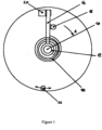
- FIG 1 the motor shaft 10 (attached to the screw of the same number 10 as that of figure 6 of the above-referenced patent, this figure, reference figure 3 , is attached for information purposes to this patent).
- a hub 12 is mounted to rotate freely on this shaft 10.
- This hub carries an arm 14 which, in this case, is pressed against an electromagnet 20, the latter, when supplied, maintains it in this position.
- a spiral spring 18 exerts on the arm 14 a force which tends to make it rotate in the direction A with a torque, for the automobile application, at least equal to 3 Nm at the end of the stroke.
- the direction of movement A corresponds to that of the application of the brake which it actuates, this direction can be reversed, if the specific characteristics of the screws and grooves of said brake justify it.
- a stop 22 will limit the stroke of the arm 14, in particular if this limit cannot be ensured by that of the stroke of the movable assembly of the brake.
- a finger 16, integral with the rotor of the motor will ensure the connection between this device which is the subject of the invention and the brake itself.
- the motor When the brake is powered up, the motor, while ensuring the brake release, goes through the finger 16, to press the arm 14 against the electromagnet 20, in a movement in the opposite direction to A (the torque required will be reversed compared to that of the braking, but of the same order of magnitude).
- the powered electromagnet will hold the arm 14 in position, the spring 18 fully loaded representing the energy storage.
- the finger 16 will then be able to move freely in the space between the two extreme points of its travel represented by the electromagnet 20 and the stop 22 (or the travel limit of the moving assembly of the brake).
- the braking device due to lack of current will have no impact on the performance of the brake, which will therefore be able to move freely in the entire space likely to be used for the various braking operations.
Landscapes
- Engineering & Computer Science (AREA)
- General Engineering & Computer Science (AREA)
- Mechanical Engineering (AREA)
- Transportation (AREA)
- Physics & Mathematics (AREA)
- Electromagnetism (AREA)
- Fluid Mechanics (AREA)
- Chemical & Material Sciences (AREA)
- Combustion & Propulsion (AREA)
- Braking Arrangements (AREA)
- Braking Systems And Boosters (AREA)
- Maintenance And Inspection Apparatuses For Elevators (AREA)
- Valves And Accessory Devices For Braking Systems (AREA)
Claims (3)
- Spannsystem der Bremsbeläge in einer Stromausfall-Bremse, wobei das Spannsystem einen Motor umfasst, der das Spannen über eine Motorwelle (10) betätigt, wobei eine auf die Bremsbeläge wirkende Kraft in einem Bereich von 0 bis 15 kN variiert, mit einer elastischen Verformung von 1 mm, wobei die für die Durchführung dieses Vorgangs erforderliche Energie 7,5 Joule beträgt, wobei ein konstantes Drehmoment von 3 Nm auf 2,5 Radiant dem Motor zugeführt wird, um diese Kraft zu liefern, wobei diese relativ niedrigen Werte des Drehmoments und des Weges eine Lösung ermöglichen, wie im Folgenden beschrieben,
das Spannsystem ist so beschaffen, dass, um bei jeder Ingangsetzung eine Energie in mindestens einer Feder zu speichern, die in der Struktur der Bremse selbst angeordnet ist, die Energie, die im Falle einer Unterbrechung der Stromversorgung der Bremse das Anziehen der Stromausfall-Bremse und ihr Halten sicherstellen wird, das Spannsystem eine Nabe (12) umfasst, die frei drehbar auf der Motorwelle (10) gelagert ist, wobei die Nabe (12) einen Arm (14) trägt, mindestens eine Feder (18), die dafür ausgelegt ist, auf den Arm (14) eine Kraft auszuüben, die bestrebt ist, ihn in einer Richtung A zu drehen, die der Richtung des Anziehens der Bremse, welche er betätigt, entspricht, und einen mit der Motorwelle fest verbundenen Finger (16), der dafür ausgelegt ist, eine Verbindung zwischen dem Spannsystem und der eigentlichen Bremse sicherzustellen; wobei das Spannsystem außerdem derart ausgebildet ist, dass bei jedem Unterspannungsetzen der Bremse der Motor, während er gleichzeitig ein Lösen der Bremse sicherstellt, über den mit der Motorwelle (10) fest verbundenen Finger (16) den Arm (14) in einer Bewegung in einer zur Richtung A entgegengesetzten Richtung an einen Elektromagneten (20) andrückt, wobei der Elektromagnet (20), der durch die Stromversorgung der Bremse gespeist wird, den Arm (14) in seiner Position und die Feder (18) maximal gespannt hält, wobei sie die Energie speichert; und im Falle eines Stromausfalls aus zufälligen oder gewollten Gründen gibt der Elektromagnet (20) den Arm (14) frei, der sich dann aufgrund der Belastung durch die Feder (18) in der Richtung A dreht; und auf seinem Weg nimmt der Arm (14) den Finger (16) mit und stellt so über die Motorwelle (10) das Festziehen der Bremse mit einem maximalen Wert und ihr Halten sicher. - Spannsystem nach Anspruch 1, welches derart ausgebildet ist, dass, wenn der Elektromagnet (20) gespeist wird, der Finger (16) sich frei in einem Raum zwischen zwei äußersten Punkten seines Weges bewegen kann, welche der Elektromagnet (20) bzw. der Anschlag (22) sind, damit das Spannsystem der Bremsbeläge in der Stromausfall-Bremse keinerlei Einfluss auf die Leistungseigenschaften der Bremse hat, die sich frei in dem gesamten Raum bewegen kann, der für die verschiedenen Bremsvorgänge verwendet werden kann.
- Spannsystem nach einem der Ansprüche 1 und 2, wobei das System dafür ausgelegt ist, als Notbremse und als Parkbremse verwendet zu werden, als Ersatz für die "Handbremse".
Applications Claiming Priority (2)
| Application Number | Priority Date | Filing Date | Title |
|---|---|---|---|
| FR1601376A FR3056271B1 (fr) | 2016-09-21 | 2016-09-21 | Systeme de freinage par manque de courant |
| PCT/FR2017/000167 WO2018055243A1 (fr) | 2016-09-21 | 2017-09-14 | Systeme de freinage par manque de courant |
Publications (2)
| Publication Number | Publication Date |
|---|---|
| EP3515768A1 EP3515768A1 (de) | 2019-07-31 |
| EP3515768B1 true EP3515768B1 (de) | 2024-11-06 |
Family
ID=57680306
Family Applications (1)
| Application Number | Title | Priority Date | Filing Date |
|---|---|---|---|
| EP17772454.9A Active EP3515768B1 (de) | 2016-09-21 | 2017-09-14 | Strom-aus-bremssystem |
Country Status (8)
| Country | Link |
|---|---|
| US (1) | US10989261B2 (de) |
| EP (1) | EP3515768B1 (de) |
| CN (1) | CN110392649B (de) |
| CA (1) | CA3037102A1 (de) |
| ES (1) | ES2996233T3 (de) |
| FR (1) | FR3056271B1 (de) |
| RU (1) | RU2744446C2 (de) |
| WO (1) | WO2018055243A1 (de) |
Families Citing this family (1)
| Publication number | Priority date | Publication date | Assignee | Title |
|---|---|---|---|---|
| DE102022211584A1 (de) | 2022-11-02 | 2024-05-02 | Robert Bosch Gesellschaft mit beschränkter Haftung | Radbremsmodul, Kraftfahrzeug, Verfahren zum Betreiben des Kraftfahrzeugs |
Family Cites Families (15)
| Publication number | Priority date | Publication date | Assignee | Title |
|---|---|---|---|---|
| FR1264059A (fr) * | 1960-05-07 | 1961-06-19 | J E Desroziers Et Cie | Frein électro-magnétique à manque de courant |
| US4947069A (en) * | 1989-06-08 | 1990-08-07 | Datatape, Inc. | Low power magnetic tape reel motor and brake assembly |
| FR2826622B1 (fr) * | 2001-07-02 | 2003-11-07 | Peugeot Citroen Automobiles Sa | Dispositif de freinage a assistance mecanique d'origine electrique |
| SE0104279D0 (en) * | 2001-12-18 | 2001-12-18 | Haldex Brake Prod Ab | A parking brake arrangement in an electrically operated brake |
| CN2583865Y (zh) | 2002-12-16 | 2003-10-29 | 苏州宝时得电动工具有限公司 | 断电后自动刹车的电动机 |
| DE112005000607B4 (de) * | 2004-03-15 | 2009-01-22 | Mitsubishi Denki K.K. | Bremsvorrichtung für einen Aufzug |
| CN100339609C (zh) | 2004-05-31 | 2007-09-26 | 常州合力电器有限公司 | 用于刀片式电动工具的电磁刹车装置 |
| WO2005121006A1 (ja) * | 2004-06-14 | 2005-12-22 | Mitsubishi Denki Kabushiki Kaisha | エレベーター用の非常ブレーキ装置 |
| FR2892963A1 (fr) | 2005-11-08 | 2007-05-11 | Jean Marc Loriot | Dispositif de rattrapage autonome d'usure. |
| US8020842B2 (en) * | 2005-11-08 | 2011-09-20 | Jean-Marc Loriot | Clamping or gripping tool comprising an autonomous compensation system |
| KR101098144B1 (ko) * | 2008-12-11 | 2011-12-26 | 현대모비스 주식회사 | 안전 제동 기능을 갖춘 제동 장치 |
| KR101574349B1 (ko) * | 2009-09-08 | 2015-12-11 | 현대모비스 주식회사 | 전자 웨지 브레이크 장치 |
| US8319384B2 (en) * | 2010-12-15 | 2012-11-27 | Honeywell International Inc. | Electromechanical brake actuator motor brake |
| CN202364166U (zh) | 2011-12-15 | 2012-08-01 | 天津市雄华电子仪表有限公司 | 电动执行器的一种单相伺服电机制动装置 |
| CN203717730U (zh) | 2014-02-27 | 2014-07-16 | 中联重科股份有限公司 | 常闭式制动器及常闭制动式回转机构 |
-
2016
- 2016-09-21 FR FR1601376A patent/FR3056271B1/fr active Active
-
2017
- 2017-09-14 US US16/335,030 patent/US10989261B2/en active Active
- 2017-09-14 EP EP17772454.9A patent/EP3515768B1/de active Active
- 2017-09-14 ES ES17772454T patent/ES2996233T3/es active Active
- 2017-09-14 CA CA3037102A patent/CA3037102A1/fr not_active Abandoned
- 2017-09-14 CN CN201780058089.9A patent/CN110392649B/zh not_active Expired - Fee Related
- 2017-09-14 WO PCT/FR2017/000167 patent/WO2018055243A1/fr not_active Ceased
- 2017-09-14 RU RU2019106948A patent/RU2744446C2/ru active
Also Published As
| Publication number | Publication date |
|---|---|
| EP3515768A1 (de) | 2019-07-31 |
| ES2996233T3 (en) | 2025-02-12 |
| RU2019106948A (ru) | 2020-09-14 |
| CN110392649A (zh) | 2019-10-29 |
| RU2019106948A3 (de) | 2020-10-05 |
| FR3056271B1 (fr) | 2022-03-11 |
| US20190249732A1 (en) | 2019-08-15 |
| US10989261B2 (en) | 2021-04-27 |
| FR3056271A1 (fr) | 2018-03-23 |
| CN110392649B (zh) | 2021-08-24 |
| WO2018055243A1 (fr) | 2018-03-29 |
| CA3037102A1 (fr) | 2018-03-29 |
| RU2744446C2 (ru) | 2021-03-09 |
Similar Documents
| Publication | Publication Date | Title |
|---|---|---|
| EP2368306B1 (de) | Elektrischer motor für einen dreh-linearen verstellantrieb | |
| JP2009209989A (ja) | サーボモータのブレーキ装置 | |
| CA2456663C (fr) | Frein electromecanique a dispositif de parc | |
| EP3515768B1 (de) | Strom-aus-bremssystem | |
| WO2015173037A1 (fr) | Actionneur bi-position et dispositif de pince avec l'actionneur | |
| FR2920744A1 (fr) | Verin de compensation pour commande de vol de giravion | |
| EP0857644B1 (de) | Scheibenbremse | |
| EP1801956B1 (de) | Anordnung zum geradlinigen Verschieben eines Objectes zwischen zwei vorgegebenen Positionen | |
| FR3016860A1 (fr) | Dispositif de blocage en rotation a structure simplifiee et actionneur comprenant un tel dispositif | |
| EP3080475A2 (de) | Trommelbremse mit einem element zum halten eines bremssegments | |
| JP2004124771A (ja) | 水平軸型風車のブレーキシステム | |
| CN111712633B (zh) | 风力发电设备中的制动装置和风力发电设备 | |
| EP4259493B1 (de) | Aktuator mit integrierter feststellbremse | |
| EP2168867A1 (de) | Teleskopischer Stellantrieb mit Haupt- und Hilstriebstange | |
| EP1610026B1 (de) | Bremssattel für eine elektromechanische Scheibenbremse | |
| FR2717303A1 (fr) | Coupe-circuit inertiel pour accumulateurs électriques d'engins auto-moteurs. | |
| EP1791242B1 (de) | Linearantrieb | |
| EP0592286B1 (de) | Verschleisszustand-Erfassungsvorrichtung für Reibbremsbeläge | |
| FR3079632B1 (fr) | Systeme de generation d'effort pour pedale de commande | |
| JP3727011B2 (ja) | 作動装置の軸受構造 | |
| WO2024188598A1 (fr) | Infrastructure photovoltaïque comprenant des moyens de mise en sécurité | |
| BE561923A (de) | ||
| FR2886266A1 (fr) | Dispositif de restitution d'un effort de butee dans un systeme de direction decouplee d'un vehicule automobile | |
| FR2757966A1 (fr) | Levier de commande d'un dispositif, resistant aux vibrations | |
| FR2915782A1 (fr) | Dispositif de freinage a friction sur un element tournant a actionneur a polymere electroactif |
Legal Events
| Date | Code | Title | Description |
|---|---|---|---|
| STAA | Information on the status of an ep patent application or granted ep patent |
Free format text: STATUS: UNKNOWN |
|
| STAA | Information on the status of an ep patent application or granted ep patent |
Free format text: STATUS: THE INTERNATIONAL PUBLICATION HAS BEEN MADE |
|
| PUAI | Public reference made under article 153(3) epc to a published international application that has entered the european phase |
Free format text: ORIGINAL CODE: 0009012 |
|
| STAA | Information on the status of an ep patent application or granted ep patent |
Free format text: STATUS: REQUEST FOR EXAMINATION WAS MADE |
|
| 17P | Request for examination filed |
Effective date: 20190321 |
|
| AK | Designated contracting states |
Kind code of ref document: A1 Designated state(s): AL AT BE BG CH CY CZ DE DK EE ES FI FR GB GR HR HU IE IS IT LI LT LU LV MC MK MT NL NO PL PT RO RS SE SI SK SM TR |
|
| AX | Request for extension of the european patent |
Extension state: BA ME |
|
| DAV | Request for validation of the european patent (deleted) | ||
| DAX | Request for extension of the european patent (deleted) | ||
| STAA | Information on the status of an ep patent application or granted ep patent |
Free format text: STATUS: EXAMINATION IS IN PROGRESS |
|
| 17Q | First examination report despatched |
Effective date: 20200421 |
|
| RAP1 | Party data changed (applicant data changed or rights of an application transferred) |
Owner name: KENDRINOV S.A. |
|
| RIN1 | Information on inventor provided before grant (corrected) |
Inventor name: SALESSE, CHRISTIAN Inventor name: LORIOT, JEAN-MARC |
|
| P01 | Opt-out of the competence of the unified patent court (upc) registered |
Effective date: 20230522 |
|
| GRAP | Despatch of communication of intention to grant a patent |
Free format text: ORIGINAL CODE: EPIDOSNIGR1 |
|
| STAA | Information on the status of an ep patent application or granted ep patent |
Free format text: STATUS: GRANT OF PATENT IS INTENDED |
|
| INTG | Intention to grant announced |
Effective date: 20240507 |
|
| GRAS | Grant fee paid |
Free format text: ORIGINAL CODE: EPIDOSNIGR3 |
|
| GRAA | (expected) grant |
Free format text: ORIGINAL CODE: 0009210 |
|
| STAA | Information on the status of an ep patent application or granted ep patent |
Free format text: STATUS: THE PATENT HAS BEEN GRANTED |
|
| AK | Designated contracting states |
Kind code of ref document: B1 Designated state(s): AL AT BE BG CH CY CZ DE DK EE ES FI FR GB GR HR HU IE IS IT LI LT LU LV MC MK MT NL NO PL PT RO RS SE SI SK SM TR |
|
| REG | Reference to a national code |
Ref country code: GB Ref legal event code: FG4D Free format text: NOT ENGLISH |
|
| REG | Reference to a national code |
Ref country code: CH Ref legal event code: EP |
|
| REG | Reference to a national code |
Ref country code: DE Ref legal event code: R096 Ref document number: 602017085940 Country of ref document: DE |
|
| REG | Reference to a national code |
Ref country code: IE Ref legal event code: FG4D Free format text: LANGUAGE OF EP DOCUMENT: FRENCH |
|
| REG | Reference to a national code |
Ref country code: ES Ref legal event code: FG2A Ref document number: 2996233 Country of ref document: ES Kind code of ref document: T3 Effective date: 20250212 |
|
| REG | Reference to a national code |
Ref country code: LT Ref legal event code: MG9D |
|
| REG | Reference to a national code |
Ref country code: NL Ref legal event code: MP Effective date: 20241106 |
|
| PG25 | Lapsed in a contracting state [announced via postgrant information from national office to epo] |
Ref country code: IS Free format text: LAPSE BECAUSE OF FAILURE TO SUBMIT A TRANSLATION OF THE DESCRIPTION OR TO PAY THE FEE WITHIN THE PRESCRIBED TIME-LIMIT Effective date: 20250306 Ref country code: PT Free format text: LAPSE BECAUSE OF FAILURE TO SUBMIT A TRANSLATION OF THE DESCRIPTION OR TO PAY THE FEE WITHIN THE PRESCRIBED TIME-LIMIT Effective date: 20250306 Ref country code: HR Free format text: LAPSE BECAUSE OF FAILURE TO SUBMIT A TRANSLATION OF THE DESCRIPTION OR TO PAY THE FEE WITHIN THE PRESCRIBED TIME-LIMIT Effective date: 20241106 |
|
| PG25 | Lapsed in a contracting state [announced via postgrant information from national office to epo] |
Ref country code: FI Free format text: LAPSE BECAUSE OF FAILURE TO SUBMIT A TRANSLATION OF THE DESCRIPTION OR TO PAY THE FEE WITHIN THE PRESCRIBED TIME-LIMIT Effective date: 20241106 Ref country code: NL Free format text: LAPSE BECAUSE OF FAILURE TO SUBMIT A TRANSLATION OF THE DESCRIPTION OR TO PAY THE FEE WITHIN THE PRESCRIBED TIME-LIMIT Effective date: 20241106 |
|
| REG | Reference to a national code |
Ref country code: AT Ref legal event code: MK05 Ref document number: 1739058 Country of ref document: AT Kind code of ref document: T Effective date: 20241106 |
|
| PG25 | Lapsed in a contracting state [announced via postgrant information from national office to epo] |
Ref country code: BG Free format text: LAPSE BECAUSE OF FAILURE TO SUBMIT A TRANSLATION OF THE DESCRIPTION OR TO PAY THE FEE WITHIN THE PRESCRIBED TIME-LIMIT Effective date: 20241106 |
|
| PG25 | Lapsed in a contracting state [announced via postgrant information from national office to epo] |
Ref country code: NO Free format text: LAPSE BECAUSE OF FAILURE TO SUBMIT A TRANSLATION OF THE DESCRIPTION OR TO PAY THE FEE WITHIN THE PRESCRIBED TIME-LIMIT Effective date: 20250206 |
|
| PG25 | Lapsed in a contracting state [announced via postgrant information from national office to epo] |
Ref country code: LV Free format text: LAPSE BECAUSE OF FAILURE TO SUBMIT A TRANSLATION OF THE DESCRIPTION OR TO PAY THE FEE WITHIN THE PRESCRIBED TIME-LIMIT Effective date: 20241106 Ref country code: GR Free format text: LAPSE BECAUSE OF FAILURE TO SUBMIT A TRANSLATION OF THE DESCRIPTION OR TO PAY THE FEE WITHIN THE PRESCRIBED TIME-LIMIT Effective date: 20250207 Ref country code: AT Free format text: LAPSE BECAUSE OF FAILURE TO SUBMIT A TRANSLATION OF THE DESCRIPTION OR TO PAY THE FEE WITHIN THE PRESCRIBED TIME-LIMIT Effective date: 20241106 |
|
| PG25 | Lapsed in a contracting state [announced via postgrant information from national office to epo] |
Ref country code: PL Free format text: LAPSE BECAUSE OF FAILURE TO SUBMIT A TRANSLATION OF THE DESCRIPTION OR TO PAY THE FEE WITHIN THE PRESCRIBED TIME-LIMIT Effective date: 20241106 |
|
| PG25 | Lapsed in a contracting state [announced via postgrant information from national office to epo] |
Ref country code: RS Free format text: LAPSE BECAUSE OF FAILURE TO SUBMIT A TRANSLATION OF THE DESCRIPTION OR TO PAY THE FEE WITHIN THE PRESCRIBED TIME-LIMIT Effective date: 20250206 |
|
| PG25 | Lapsed in a contracting state [announced via postgrant information from national office to epo] |
Ref country code: SM Free format text: LAPSE BECAUSE OF FAILURE TO SUBMIT A TRANSLATION OF THE DESCRIPTION OR TO PAY THE FEE WITHIN THE PRESCRIBED TIME-LIMIT Effective date: 20241106 |
|
| PG25 | Lapsed in a contracting state [announced via postgrant information from national office to epo] |
Ref country code: DK Free format text: LAPSE BECAUSE OF FAILURE TO SUBMIT A TRANSLATION OF THE DESCRIPTION OR TO PAY THE FEE WITHIN THE PRESCRIBED TIME-LIMIT Effective date: 20241106 |
|
| PG25 | Lapsed in a contracting state [announced via postgrant information from national office to epo] |
Ref country code: EE Free format text: LAPSE BECAUSE OF FAILURE TO SUBMIT A TRANSLATION OF THE DESCRIPTION OR TO PAY THE FEE WITHIN THE PRESCRIBED TIME-LIMIT Effective date: 20241106 |
|
| PG25 | Lapsed in a contracting state [announced via postgrant information from national office to epo] |
Ref country code: RO Free format text: LAPSE BECAUSE OF FAILURE TO SUBMIT A TRANSLATION OF THE DESCRIPTION OR TO PAY THE FEE WITHIN THE PRESCRIBED TIME-LIMIT Effective date: 20241106 |
|
| PG25 | Lapsed in a contracting state [announced via postgrant information from national office to epo] |
Ref country code: SK Free format text: LAPSE BECAUSE OF FAILURE TO SUBMIT A TRANSLATION OF THE DESCRIPTION OR TO PAY THE FEE WITHIN THE PRESCRIBED TIME-LIMIT Effective date: 20241106 |
|
| PG25 | Lapsed in a contracting state [announced via postgrant information from national office to epo] |
Ref country code: CZ Free format text: LAPSE BECAUSE OF FAILURE TO SUBMIT A TRANSLATION OF THE DESCRIPTION OR TO PAY THE FEE WITHIN THE PRESCRIBED TIME-LIMIT Effective date: 20241106 |
|
| PG25 | Lapsed in a contracting state [announced via postgrant information from national office to epo] |
Ref country code: IT Free format text: LAPSE BECAUSE OF FAILURE TO SUBMIT A TRANSLATION OF THE DESCRIPTION OR TO PAY THE FEE WITHIN THE PRESCRIBED TIME-LIMIT Effective date: 20241106 |
|
| REG | Reference to a national code |
Ref country code: DE Ref legal event code: R097 Ref document number: 602017085940 Country of ref document: DE |
|
| PG25 | Lapsed in a contracting state [announced via postgrant information from national office to epo] |
Ref country code: SE Free format text: LAPSE BECAUSE OF FAILURE TO SUBMIT A TRANSLATION OF THE DESCRIPTION OR TO PAY THE FEE WITHIN THE PRESCRIBED TIME-LIMIT Effective date: 20241106 |
|
| PLBE | No opposition filed within time limit |
Free format text: ORIGINAL CODE: 0009261 |
|
| STAA | Information on the status of an ep patent application or granted ep patent |
Free format text: STATUS: NO OPPOSITION FILED WITHIN TIME LIMIT |
|
| REG | Reference to a national code |
Ref country code: CH Ref legal event code: U11 Free format text: ST27 STATUS EVENT CODE: U-0-0-U10-U11 (AS PROVIDED BY THE NATIONAL OFFICE) Effective date: 20251001 |
|
| PGFP | Annual fee paid to national office [announced via postgrant information from national office to epo] |
Ref country code: DE Payment date: 20250919 Year of fee payment: 9 |
|
| 26N | No opposition filed |
Effective date: 20250807 |
|
| PGFP | Annual fee paid to national office [announced via postgrant information from national office to epo] |
Ref country code: FR Payment date: 20250922 Year of fee payment: 9 |
|
| PGFP | Annual fee paid to national office [announced via postgrant information from national office to epo] |
Ref country code: CH Payment date: 20251001 Year of fee payment: 9 |
|
| PGFP | Annual fee paid to national office [announced via postgrant information from national office to epo] |
Ref country code: ES Payment date: 20251030 Year of fee payment: 9 |