EP3514853B1 - Zellenkartusche und batteriemodul damit - Google Patents
Zellenkartusche und batteriemodul damit Download PDFInfo
- Publication number
- EP3514853B1 EP3514853B1 EP18841460.1A EP18841460A EP3514853B1 EP 3514853 B1 EP3514853 B1 EP 3514853B1 EP 18841460 A EP18841460 A EP 18841460A EP 3514853 B1 EP3514853 B1 EP 3514853B1
- Authority
- EP
- European Patent Office
- Prior art keywords
- cell
- pouch
- pouch cell
- cartridge
- fixing portion
- Prior art date
- Legal status (The legal status is an assumption and is not a legal conclusion. Google has not performed a legal analysis and makes no representation as to the accuracy of the status listed.)
- Active
Links
Images


Classifications
-
- H—ELECTRICITY
- H01—ELECTRIC ELEMENTS
- H01M—PROCESSES OR MEANS, e.g. BATTERIES, FOR THE DIRECT CONVERSION OF CHEMICAL ENERGY INTO ELECTRICAL ENERGY
- H01M50/00—Constructional details or processes of manufacture of the non-active parts of electrochemical cells other than fuel cells, e.g. hybrid cells
- H01M50/20—Mountings; Secondary casings or frames; Racks, modules or packs; Suspension devices; Shock absorbers; Transport or carrying devices; Holders
-
- H—ELECTRICITY
- H01—ELECTRIC ELEMENTS
- H01M—PROCESSES OR MEANS, e.g. BATTERIES, FOR THE DIRECT CONVERSION OF CHEMICAL ENERGY INTO ELECTRICAL ENERGY
- H01M50/00—Constructional details or processes of manufacture of the non-active parts of electrochemical cells other than fuel cells, e.g. hybrid cells
- H01M50/10—Primary casings; Jackets or wrappings
- H01M50/102—Primary casings; Jackets or wrappings characterised by their shape or physical structure
- H01M50/103—Primary casings; Jackets or wrappings characterised by their shape or physical structure prismatic or rectangular
-
- H—ELECTRICITY
- H01—ELECTRIC ELEMENTS
- H01M—PROCESSES OR MEANS, e.g. BATTERIES, FOR THE DIRECT CONVERSION OF CHEMICAL ENERGY INTO ELECTRICAL ENERGY
- H01M50/00—Constructional details or processes of manufacture of the non-active parts of electrochemical cells other than fuel cells, e.g. hybrid cells
- H01M50/10—Primary casings; Jackets or wrappings
- H01M50/102—Primary casings; Jackets or wrappings characterised by their shape or physical structure
- H01M50/105—Pouches or flexible bags
-
- H—ELECTRICITY
- H01—ELECTRIC ELEMENTS
- H01M—PROCESSES OR MEANS, e.g. BATTERIES, FOR THE DIRECT CONVERSION OF CHEMICAL ENERGY INTO ELECTRICAL ENERGY
- H01M50/00—Constructional details or processes of manufacture of the non-active parts of electrochemical cells other than fuel cells, e.g. hybrid cells
- H01M50/10—Primary casings; Jackets or wrappings
- H01M50/116—Primary casings; Jackets or wrappings characterised by the material
- H01M50/117—Inorganic material
- H01M50/119—Metals
-
- H—ELECTRICITY
- H01—ELECTRIC ELEMENTS
- H01M—PROCESSES OR MEANS, e.g. BATTERIES, FOR THE DIRECT CONVERSION OF CHEMICAL ENERGY INTO ELECTRICAL ENERGY
- H01M50/00—Constructional details or processes of manufacture of the non-active parts of electrochemical cells other than fuel cells, e.g. hybrid cells
- H01M50/10—Primary casings; Jackets or wrappings
- H01M50/116—Primary casings; Jackets or wrappings characterised by the material
- H01M50/121—Organic material
-
- H—ELECTRICITY
- H01—ELECTRIC ELEMENTS
- H01M—PROCESSES OR MEANS, e.g. BATTERIES, FOR THE DIRECT CONVERSION OF CHEMICAL ENERGY INTO ELECTRICAL ENERGY
- H01M50/00—Constructional details or processes of manufacture of the non-active parts of electrochemical cells other than fuel cells, e.g. hybrid cells
- H01M50/10—Primary casings; Jackets or wrappings
- H01M50/116—Primary casings; Jackets or wrappings characterised by the material
- H01M50/124—Primary casings; Jackets or wrappings characterised by the material having a layered structure
- H01M50/126—Primary casings; Jackets or wrappings characterised by the material having a layered structure comprising three or more layers
- H01M50/129—Primary casings; Jackets or wrappings characterised by the material having a layered structure comprising three or more layers with two or more layers of only organic material
-
- H—ELECTRICITY
- H01—ELECTRIC ELEMENTS
- H01M—PROCESSES OR MEANS, e.g. BATTERIES, FOR THE DIRECT CONVERSION OF CHEMICAL ENERGY INTO ELECTRICAL ENERGY
- H01M50/00—Constructional details or processes of manufacture of the non-active parts of electrochemical cells other than fuel cells, e.g. hybrid cells
- H01M50/20—Mountings; Secondary casings or frames; Racks, modules or packs; Suspension devices; Shock absorbers; Transport or carrying devices; Holders
- H01M50/204—Racks, modules or packs for multiple batteries or multiple cells
- H01M50/207—Racks, modules or packs for multiple batteries or multiple cells characterised by their shape
- H01M50/209—Racks, modules or packs for multiple batteries or multiple cells characterised by their shape adapted for prismatic or rectangular cells
-
- H—ELECTRICITY
- H01—ELECTRIC ELEMENTS
- H01M—PROCESSES OR MEANS, e.g. BATTERIES, FOR THE DIRECT CONVERSION OF CHEMICAL ENERGY INTO ELECTRICAL ENERGY
- H01M50/00—Constructional details or processes of manufacture of the non-active parts of electrochemical cells other than fuel cells, e.g. hybrid cells
- H01M50/20—Mountings; Secondary casings or frames; Racks, modules or packs; Suspension devices; Shock absorbers; Transport or carrying devices; Holders
- H01M50/204—Racks, modules or packs for multiple batteries or multiple cells
- H01M50/207—Racks, modules or packs for multiple batteries or multiple cells characterised by their shape
- H01M50/211—Racks, modules or packs for multiple batteries or multiple cells characterised by their shape adapted for pouch cells
-
- H—ELECTRICITY
- H01—ELECTRIC ELEMENTS
- H01M—PROCESSES OR MEANS, e.g. BATTERIES, FOR THE DIRECT CONVERSION OF CHEMICAL ENERGY INTO ELECTRICAL ENERGY
- H01M50/00—Constructional details or processes of manufacture of the non-active parts of electrochemical cells other than fuel cells, e.g. hybrid cells
- H01M50/20—Mountings; Secondary casings or frames; Racks, modules or packs; Suspension devices; Shock absorbers; Transport or carrying devices; Holders
- H01M50/262—Mountings; Secondary casings or frames; Racks, modules or packs; Suspension devices; Shock absorbers; Transport or carrying devices; Holders with fastening means, e.g. locks
- H01M50/264—Mountings; Secondary casings or frames; Racks, modules or packs; Suspension devices; Shock absorbers; Transport or carrying devices; Holders with fastening means, e.g. locks for cells or batteries, e.g. straps, tie rods or peripheral frames
-
- H—ELECTRICITY
- H01—ELECTRIC ELEMENTS
- H01M—PROCESSES OR MEANS, e.g. BATTERIES, FOR THE DIRECT CONVERSION OF CHEMICAL ENERGY INTO ELECTRICAL ENERGY
- H01M50/00—Constructional details or processes of manufacture of the non-active parts of electrochemical cells other than fuel cells, e.g. hybrid cells
- H01M50/50—Current conducting connections for cells or batteries
- H01M50/531—Electrode connections inside a battery casing
-
- H—ELECTRICITY
- H01—ELECTRIC ELEMENTS
- H01M—PROCESSES OR MEANS, e.g. BATTERIES, FOR THE DIRECT CONVERSION OF CHEMICAL ENERGY INTO ELECTRICAL ENERGY
- H01M50/00—Constructional details or processes of manufacture of the non-active parts of electrochemical cells other than fuel cells, e.g. hybrid cells
- H01M50/50—Current conducting connections for cells or batteries
- H01M50/543—Terminals
- H01M50/547—Terminals characterised by the disposition of the terminals on the cells
- H01M50/55—Terminals characterised by the disposition of the terminals on the cells on the same side of the cell
-
- H—ELECTRICITY
- H01—ELECTRIC ELEMENTS
- H01M—PROCESSES OR MEANS, e.g. BATTERIES, FOR THE DIRECT CONVERSION OF CHEMICAL ENERGY INTO ELECTRICAL ENERGY
- H01M50/00—Constructional details or processes of manufacture of the non-active parts of electrochemical cells other than fuel cells, e.g. hybrid cells
- H01M50/50—Current conducting connections for cells or batteries
- H01M50/543—Terminals
- H01M50/552—Terminals characterised by their shape
- H01M50/553—Terminals adapted for prismatic, pouch or rectangular cells
- H01M50/557—Plate-shaped terminals
-
- Y—GENERAL TAGGING OF NEW TECHNOLOGICAL DEVELOPMENTS; GENERAL TAGGING OF CROSS-SECTIONAL TECHNOLOGIES SPANNING OVER SEVERAL SECTIONS OF THE IPC; TECHNICAL SUBJECTS COVERED BY FORMER USPC CROSS-REFERENCE ART COLLECTIONS [XRACs] AND DIGESTS
- Y02—TECHNOLOGIES OR APPLICATIONS FOR MITIGATION OR ADAPTATION AGAINST CLIMATE CHANGE
- Y02E—REDUCTION OF GREENHOUSE GAS [GHG] EMISSIONS, RELATED TO ENERGY GENERATION, TRANSMISSION OR DISTRIBUTION
- Y02E60/00—Enabling technologies; Technologies with a potential or indirect contribution to GHG emissions mitigation
- Y02E60/10—Energy storage using batteries
Definitions
- the present disclosure relates to a battery module capable of preventing relative movement of pouch cells, and more particularly, to a battery module having a binding structure between pouch cells so that a pair of pouch cells included in an individual cell cartridge is prevented from moving relative to each other.
- a cell cartridge comprising a first pouch cell, a second pouch cell and a cartridge configured to accommodate a cell stack formed by stacking the first pouch cell and the second pouch cell.
- both surfaces of the stack are pressed using end plates that cover both broad surfaces of the stack, thereby just preventing the battery cells from moving along a direction parallel to the stacking direction of the battery cells.
- the structure of the conventional battery module is inevitably vulnerable to movement in a direction perpendicular to the stacking direction of battery cells. This is because the battery cells may also move due to the minute space present between the battery cell and an inner wall of the module case accommodating the battery cells.
- the battery cell may be damaged while the battery module is in use, thereby deteriorating the safety and reliability of the product.
- the present disclosure is designed to solve the problems of the related art, and therefore the present disclosure is directed to providing a binding structure, which may prevent battery cells from moving in a direction perpendicular to a stacking direction of the battery cells in the battery module.
- a cell cartridge comprising: a first pouch cell having a first fixing portion extending out of a sealing portion of the first pouch cell;
- the first fixing portion and the second fixing portion may be respectively provided in plural.
- the plurality of first fixing portions may be provided to be spaced apart from each other along a periphery of the first pouch cell, and the plurality of second fixing portions may be provided to be spaced apart from each other along a periphery of the second pouch cell.
- the first fixing portions may be formed in a region except for an area where an electrode lead of the first pouch cell is drawn, and the second fixing portions may be formed in a region except for an area where an electrode lead of the second pouch cell is drawn.
- the first fixing portions and the second fixing portions may be arranged alternately along a periphery of the cell stack.
- the first fixing portion may extend to an accommodation portion of the second pouch cell and is attached to the second pouch cell
- the second fixing portion may extend to an accommodation portion of the first pouch cell and is attached to the first pouch cell
- the first fixing portion and the second fixing portion may be respectively integrally formed with the sealing portion of the first pouch cell and the sealing portion of the second pouch cell.
- a battery module which comprises a cell cartridge stack formed by stacking a plurality of cell cartridges according to an embodiment of the present disclosure; and a pair of end plates configured to cover both surfaces of the cell cartridge stack.
- the present disclosure it is possible to prevent battery cells from moving in a direction perpendicular to a stacking direction of the battery cells inside a cartridge, thereby reducing damage caused to the pouch cells due to movement of the pair of pouch cells in the cartridge and also reducing the occurrence of a failed battery module and the danger in use of the battery module.
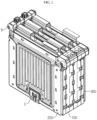
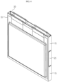
- FIG. 1 is a perspective view showing a battery module according to an embodiment of the present disclosure in an assembled state
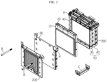
- FIG. 2 is an exploded perspective view showing the battery module according to an embodiment of the present disclosure
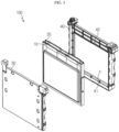
- FIG. 3 is an exploded perspective view showing a cell cartridge according to an embodiment of the present disclosure.
- a battery module includes a cell cartridge stack formed by stacking a plurality of cell cartridges 100 and a pair of end plates 200, 300 covering both surfaces of the cell cartridge stack.
- the cell cartridge 100 includes a cell stack formed by stacking a pair of pouch cells 10, 20 and a cartridge 50 for accommodating the cell stack.
- the cartridge 50 includes a first cartridge 30 coupled to one side surface of the cell stack and a second cartridge 40 coupled to the other side surface of the cell stack.
- the pair of first cartridge 30 and second cartridge 40 of the cell cartridge 100 and the end plates 200, 300 have fastening holes H formed in corner regions at both sides of a top portion thereof.
- a fastening bolt B is inserted into the fastening holes H so that the first cartridge 30 and the second cartridge 40 are fastened together and the plurality of cell cartridges 100 are fastened together.
- a fastening clip C is mounted at a bottom center of the pair of end plates 200, 300, respectively, so that the binding force between the end plates 200, 300 may be more firmly maintained.
- the cell cartridge stack and the end plates 200, 300 are also fastened to each other, and by doing so, the end plates 200, 300 press the cell cartridge stack so that the plurality of cell cartridges 100 are prevented from moving relative to each other.
- the figures of the present disclosure depict only a case where three cell cartridges 100 are included in one battery module, the present disclosure is not limited thereto, and the number of cell cartridges 100 may be increased or decreased depending on the required battery voltage and/or capacity.
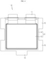
- FIG. 4 is a plane view showing a first pouch cell employed in the present disclosure
- FIG. 5 is a plane view showing a second pouch cell employed in the present disclosure
- FIG. 6 is a perspective view showing a state where the first pouch cell and the second pouch cell employed in the present disclosure are bound.
- the first pouch cell 10 of the cell cartridge 100 includes an electrode assembly (not shown), a pair of electrode leads 11, a pouch case 12, and a plurality of first fixing portions 15.
- the electrode assembly is configured so that separators are interposed between positive electrode plates and negative electrode plates, which are alternately stacked on one another, and the separators are preferably located at both outermost sides of the electrode assembly for insulation.
- the positive electrode plate includes a positive electrode current collector and a positive electrode active material layer coated on at least one surface of the positive electrode current collector.
- a positive electrode uncoated region not coated with a positive electrode active material is formed on one side end of the positive electrode current collector, and the positive electrode uncoated region functions as a positive electrode tab connected to the electrode lead 11.
- the negative electrode plate includes a negative electrode current collector and a negative electrode active material layer coated on at least one surface of the negative electrode current collector.
- An uncoated region not coated with a negative electrode active material is formed on one side end of the negative electrode current collector, and the uncoated region functions as a negative electrode tab connected to the electrode lead 11.
- the separator is interposed between the positive electrode plate and the negative electrode plate to prevent the electrode plates having different polarities from directly contacting each other.
- the separator may be made of a porous material in order to allow ions to move between the positive electrode plate and the negative electrode plate by using the electrolyte as a medium.
- the electrode lead 11 is classified into a positive electrode lead connected to the positive electrode tab and a negative electrode lead connected to the negative electrode tab, and the positive and negative electrode leads are drawn and extended in parallel in one direction of the pouch case 12.
- the pouch case 12 may include an upper case covering an upper portion of the electrode assembly and a lower case covering a lower portion thereof, and the upper case and the lower case may respectively be a multilayered pouch film including a first resin layer, a metal layer and a second resin layer.
- the first resin layer forming an innermost side of the pouch film may be made of a resin with a heat-fusing property so that the upper and lower cases may be easily fused to each other when heat is applied thereto in a state where the upper and lower cases are in contact with each other.
- the pouch case 12 includes two portions, namely an accommodation portion 13 for accommodating the electrode assembly (not shown) and a sealing portion 14 extending along the circumferential direction the accommodation portion.
- the sealing portion 14 is thermally fused in a state in which the electrode lead 11 is drawn out to the outside of the pouch case 12 to seal the pouch case 12.
- the first fixing portion 15 is provided to extend outward from the sealing portion 14 of the first pouch cell 10 and is bent toward the second pouch cell 20 stacked to face the first pouch cell 10, thereby restricting movement of the second pouch cell 20.
- the first fixing portion 15 is provided in plural, and the plurality of first fixing portions 15 are spaced apart from each other along a periphery of the first pouch cell 10 and are formed except for a region where the electrode leads 11 are drawn out.
- the second pouch cell 20 includes an electrode assembly (not shown), a pair of electrode leads 21, a pouch case 22, and a plurality of second fixing portions 25.
- the first pouch cell 10 and the second pouch cell 20 are substantially identical to each other except the locations where the fixing portions 15, 25 are formed. Thus, the components other than the second fixing portion 25 will not be described in detail here.
- the second fixing portion 25 is provided to extend outward from a sealing portion 24 of the second pouch cell 20 and is bent toward the first pouch cell 10 stacked to face the second pouch cell 20 to restrict movement of the first pouch cell 10.
- the second fixing portion 25 is provided in plural, and the plurality of second fixing portions 25 are spaced apart from each other along a periphery of the second pouch cell 20 and are formed except for a region where the electrode leads 21 are drawn out.
- the second fixing portion 25 is provided at a position where the first fixing portion 15 is not formed when the first pouch cell 10 and the second pouch cell 20 are stacked. Accordingly, the first fixing portions 15 and the second fixing portions 25 are alternately arranged along the periphery of the cell stack formed by stacking the first pouch cell 10 and the second pouch cell 20.
- the binding force between the pair of pouch cells 10, 20 is increased due to the fixing portions 15, 25, which are bent toward the pouch cells 20, 10 located at the opposite sides, so that the first pouch cell 10 and the second pouch cell 20 do not move relative to each other.
- the fixing portions 15, 25 are integrally formed with the pouch cases 12, 22 and are substantially formed by elongating the sealing portions 14, 24 longer toward the outside.
- FIG. 7 is a perspective view showing a state where the first pouch cell and the second pouch cell employed in the present disclosure are bound by applying a binding pattern different from FIG. 6 .
- the cell stack shown in FIG. 7 is substantially identical to the cell stack shown in FIG. 6 , except that the fixing portions 15, 25 are formed longer and attached to the outer surface of the cell stack.
- the fixing portions 15, 25 may extend to the accommodation portions 13, 23 of the pouch cells 20, 10 at opposite sides and be attached onto the accommodation portions 13, 23 by an adhesive or the like. By doing so, the binding force between the first pouch cell 10 and the second pouch cell 20 is increased further so that the first pouch cell 10 and the second pouch cell 20 do not move relative to each other inside the cartridge 50.
- the cell stack having the above structure with an enhanced binding force is accommodated in the cartridge 50.
- the cartridge 50 includes a first cartridge 30 coupled to one side surface of the cell stack and a second cartridge 40 coupled to the other side surface of the cell stack.
- Each of the cartridges 30, 40 has a cell accommodation portion 41 for giving a space in which the pouch cells 10, 20 may be accommodated, and a lead drawing portion 42 giving a space through which the electrode leads 11, 21 may be drawn out of the cartridge 50.
- the electrode leads drawn through the lead drawing portion 42 are connected to each other, thereby implementing a battery module in which the plurality of pouch cells are connected in series, in parallel, or a combination thereof.
Landscapes
- Chemical & Material Sciences (AREA)
- Chemical Kinetics & Catalysis (AREA)
- Electrochemistry (AREA)
- General Chemical & Material Sciences (AREA)
- Inorganic Chemistry (AREA)
- Battery Mounting, Suspending (AREA)
- Sealing Battery Cases Or Jackets (AREA)
Claims (8)
- Zellenkartusche (100), umfassend:eine erste Beutelzelle (10), welche einen ersten Befestigungsabschnitt (15) aufweist, welcher sich aus einem Dichtungsabschnitt (14) der ersten Beutelzelle (10) heraus erstreckt;eine zweite Beutelzelle (20), welche einen zweiten Befestigungsabschnitt (25) aufweist, welcher sich aus einem Dichtungsabschnitt (24) der zweiten Beutelzelle (20) heraus erstreckt; undeine Kartusche (50), welche dazu eingerichtet ist, einen Zellenstapel aufzunehmen, welcher durch Stapeln der ersten Beutelzelle (10) und der zweiten Beutelzelle (20) gebildet ist,wobei der erste Befestigungsabschnitt (15) in Richtung der zweiten Beutelzelle (20) gebogen ist, um eine Bewegung der zweiten Beutelzelle (20) zu beschränken, undwobei der zweite Befestigungsabschnitt (25) in Richtung der ersten Beutelzelle (10) gebogen ist, um eine Bewegung der ersten Beutelzelle (10) zu beschränken.
- Zellenkartusche nach Anspruch 1,
wobei der erste Befestigungsabschnitt (15) und der zweite Befestigungsabschnitt (25) jeweils mehrfach bereitgestellt sind - Zellenkartusche nach Anspruch 2,wobei die Mehrzahl von ersten Befestigungsabschnitten (15) derart bereitgestellt sind, dass sie voneinander entlang eines Umfangs der ersten Beutelzelle (10) beabstandet sind, undwobei die Mehrzahl von zweiten Befestigungsabschnitten (25) derart bereitgestellt sind, dass sie voneinander entlang eines Umfangs der zweiten Beutelzelle (20) beabstandet sind.
- Zellenkartusche nach Anspruch 3,wobei die ersten Befestigungsabschnitte (15) in einer Region gebildet sind, mit Ausnahme eines Bereichs, in welchem eine Elektrodenleitung (11) der ersten Beutelzelle (10) gezogen ist, undwobei die zweiten Befestigungsabschnitte (25) in einer Region gebildet sind, mit Ausnahme eines Bereichs, in welchem eine Elektrodenleitung (21) der zweiten Beutelzelle (20) gezogen ist.
- Zellenkartusche nach Anspruch 3,
wobei die ersten Befestigungsabschnitte (15) und die zweiten Befestigungsabschnitte (25) abwechselnd entlang eines Umfangs des Zellenstapels angeordnet sind. - Zellenkartusche nach Anspruch 1,wobei sich der erste Befestigungsabschnitt (15) zu einem Aufnahmeabschnitt der zweiten Beutelzelle (20) erstreckt und an der zweiten Beutelzelle (20) angebracht ist, undwobei sich der zweite Befestigungsabschnitt (25) zu einem Aufnahmeabschnitt der ersten Beutelzelle (10) erstreckt und an der ersten Beutelzelle (10) angebracht ist.
- Zellenkartusche nach Anspruch 1,
wobei der erste Befestigungsabschnitt (15) und der zweite Befestigungsabschnitt (25) jeweils integral mit dem Dichtungsabschnitt der ersten Beutelzelle und dem Dichtungsabschnitt der zweiten Beutelzelle gebildet sind. - Batteriemodul, umfassend:einen Zellenkartuschen (50)-Stapel, welcher durch Stapeln einer Mehrzahl von Zellenkartuschen gebildet ist, welche in Anspruch 1 definiert sind; undein Paar von Endplatten (200; 300), welche dazu eingerichtet sind, beide Flächen des Zellenkartuschen-Stapels zu bedecken.
Applications Claiming Priority (2)
| Application Number | Priority Date | Filing Date | Title |
|---|---|---|---|
| KR1020170096809A KR102160275B1 (ko) | 2017-07-31 | 2017-07-31 | 셀 카트리지 및 이를 포함하는 배터리 모듈 |
| PCT/KR2018/008188 WO2019027162A1 (ko) | 2017-07-31 | 2018-07-19 | 셀 카트리지 및 이를 포함하는 배터리 모듈 |
Publications (3)
| Publication Number | Publication Date |
|---|---|
| EP3514853A1 EP3514853A1 (de) | 2019-07-24 |
| EP3514853A4 EP3514853A4 (de) | 2019-11-13 |
| EP3514853B1 true EP3514853B1 (de) | 2025-01-01 |
Family
ID=65234076
Family Applications (1)
| Application Number | Title | Priority Date | Filing Date |
|---|---|---|---|
| EP18841460.1A Active EP3514853B1 (de) | 2017-07-31 | 2018-07-19 | Zellenkartusche und batteriemodul damit |
Country Status (8)
| Country | Link |
|---|---|
| US (1) | US11088417B2 (de) |
| EP (1) | EP3514853B1 (de) |
| JP (1) | JP7034414B2 (de) |
| KR (1) | KR102160275B1 (de) |
| CN (1) | CN109891623B (de) |
| ES (1) | ES3003808T3 (de) |
| HU (1) | HUE070243T2 (de) |
| WO (1) | WO2019027162A1 (de) |
Families Citing this family (3)
| Publication number | Priority date | Publication date | Assignee | Title |
|---|---|---|---|---|
| TWM594276U (zh) | 2019-12-16 | 2020-04-21 | 財團法人工業技術研究院 | 電池模組 |
| KR102774863B1 (ko) * | 2020-03-12 | 2025-03-04 | 주식회사 엘지에너지솔루션 | 조립이 용이한 전지 모듈 및 이를 포함하는 전지 팩 |
| DE102020213244A1 (de) * | 2020-10-20 | 2022-04-21 | Volkswagen Aktiengesellschaft | Zellanordnung für eine Hochvoltbatterie, insbesondere Zellpack oder Zellmodul |
Family Cites Families (26)
| Publication number | Priority date | Publication date | Assignee | Title |
|---|---|---|---|---|
| JP3963165B2 (ja) | 2003-10-10 | 2007-08-22 | 日産自動車株式会社 | 組電池 |
| JP5227494B2 (ja) * | 2005-06-02 | 2013-07-03 | 株式会社東芝 | 組電池の電池パック |
| JP5374979B2 (ja) | 2008-09-10 | 2013-12-25 | 株式会社村田製作所 | 電池と組電池 |
| CA2761758C (en) | 2009-05-11 | 2015-03-24 | Magna Steyr Fahrzeugtechnik Ag & Co Kg | Battery unit |
| US20110123844A1 (en) | 2009-11-20 | 2011-05-26 | Apple Inc. | Pressure-relief mechanism to improve safety in lithium-polymer battery cells |
| KR101093890B1 (ko) * | 2010-01-12 | 2011-12-13 | 삼성에스디아이 주식회사 | 이차전지 |
| KR101073010B1 (ko) | 2010-04-19 | 2011-10-12 | 삼성에스디아이 주식회사 | 이차 전지 |
| US9203065B2 (en) * | 2010-08-10 | 2015-12-01 | Samsung Sdi Co., Ltd. | Battery module |
| JP3169685U (ja) | 2011-05-31 | 2011-08-11 | 古河電池株式会社 | 電池モジュール |
| FR2993708B1 (fr) * | 2012-07-17 | 2014-11-07 | Renault Sas | Module de batterie d'accumulateurs a cellules comprimees |
| JP6202643B2 (ja) * | 2013-03-15 | 2017-09-27 | Necエナジーデバイス株式会社 | 組電池 |
| KR101658973B1 (ko) | 2013-09-23 | 2016-09-22 | 주식회사 엘지화학 | 파우치형 이차전지 및 이를 포함하는 이차전지 모듈 |
| JP5858074B2 (ja) * | 2014-03-13 | 2016-02-10 | 株式会社豊田自動織機 | 蓄電装置 |
| JP6487461B2 (ja) * | 2014-05-08 | 2019-03-20 | エルジー・ケム・リミテッド | ノイズ低減部材を含む電池パック |
| KR102222112B1 (ko) * | 2014-07-16 | 2021-03-03 | 삼성에스디아이 주식회사 | 가요성 이차 전지 |
| KR102280687B1 (ko) * | 2014-09-25 | 2021-07-22 | 삼성전자주식회사 | 전극조립체를 구비하는 플렉서블 전기화학소자 |
| JP6641711B2 (ja) * | 2015-03-27 | 2020-02-05 | 株式会社豊田自動織機 | 電池モジュール |
| US20170030290A1 (en) * | 2015-07-30 | 2017-02-02 | General Electric Company | Recess to encourage ring lift |
| KR101979888B1 (ko) * | 2015-08-19 | 2019-05-17 | 주식회사 엘지화학 | 배터리 모듈, 배터리 모듈을 포함하는 배터리 팩 및 배터리 팩을 포함하는 자동차 |
| KR101937943B1 (ko) * | 2015-09-02 | 2019-01-11 | 주식회사 엘지화학 | 이차 전지용 카트리지 |
| KR20170055144A (ko) | 2015-11-11 | 2017-05-19 | 주식회사 엘지화학 | 이중 절곡 구조의 실링부를 포함하는 파우치형 전지셀 |
| KR102082383B1 (ko) * | 2015-11-30 | 2020-02-27 | 주식회사 엘지화학 | 구성이 간소화된 단위모듈을 포함하고 있는 전지모듈 |
| KR20170073856A (ko) | 2015-12-21 | 2017-06-29 | 주식회사 엘지화학 | 외주변 실링부에 형성된 일체형 지지부재를 포함하고 있는 전지셀 |
| KR101916720B1 (ko) | 2016-01-05 | 2018-11-08 | 엘지전자 주식회사 | 배터리 모듈 및 그 제조방법, 배터리 모듈을 이용한 전기 자동차 |
| KR102067714B1 (ko) | 2016-11-17 | 2020-01-17 | 주식회사 엘지화학 | 배터리 모듈 및 이를 포함하는 배터리 팩 |
| KR102082498B1 (ko) * | 2017-04-26 | 2020-02-27 | 주식회사 엘지화학 | 전극 리드와 버스바의 결합 구조가 개선된 배터리 모듈 및 그 제조 방법 |
-
2017
- 2017-07-31 KR KR1020170096809A patent/KR102160275B1/ko active Active
-
2018
- 2018-07-19 ES ES18841460T patent/ES3003808T3/es active Active
- 2018-07-19 HU HUE18841460A patent/HUE070243T2/hu unknown
- 2018-07-19 CN CN201880003892.7A patent/CN109891623B/zh active Active
- 2018-07-19 EP EP18841460.1A patent/EP3514853B1/de active Active
- 2018-07-19 WO PCT/KR2018/008188 patent/WO2019027162A1/ko not_active Ceased
- 2018-07-19 US US16/333,524 patent/US11088417B2/en active Active
- 2018-07-19 JP JP2019528759A patent/JP7034414B2/ja active Active
Also Published As
| Publication number | Publication date |
|---|---|
| EP3514853A4 (de) | 2019-11-13 |
| CN109891623A (zh) | 2019-06-14 |
| KR102160275B1 (ko) | 2020-09-25 |
| JP2020503643A (ja) | 2020-01-30 |
| CN109891623B (zh) | 2022-03-18 |
| KR20190012980A (ko) | 2019-02-11 |
| ES3003808T3 (en) | 2025-03-11 |
| JP7034414B2 (ja) | 2022-03-14 |
| HUE070243T2 (hu) | 2025-05-28 |
| US11088417B2 (en) | 2021-08-10 |
| US20190267587A1 (en) | 2019-08-29 |
| EP3514853A1 (de) | 2019-07-24 |
| WO2019027162A1 (ko) | 2019-02-07 |
Similar Documents
| Publication | Publication Date | Title |
|---|---|---|
| JP6730431B2 (ja) | バッテリーモジュール及びそれを含むバッテリーパック、自動車 | |
| EP2299511B1 (de) | Wiederaufladbare Batterie und Batteriemodul | |
| EP2975669B1 (de) | Batteriemodul mit verbesserten vibrationseigenschaften und daran angebrachte rahmenkartuschenanordnung | |
| EP2610945B1 (de) | Stapelzelle | |
| US20120115011A1 (en) | Battery module having battery cell holder | |
| US10686165B2 (en) | Electrode assembly and secondary battery including the same | |
| KR102874645B1 (ko) | 전극 조립체 및 이를 포함하는 이차 전지 | |
| US20160365544A1 (en) | Secondary battery | |
| EP2450990B1 (de) | Batteriemodul mit Batteriezellenhalter | |
| CN105322210A (zh) | 可再充电电池 | |
| US20150221925A1 (en) | Stacked type secondary battery | |
| CN102456909A (zh) | 可再充电电池 | |
| EP3514853B1 (de) | Zellenkartusche und batteriemodul damit | |
| US9048487B2 (en) | Secondary battery and manufacturing method thereof | |
| US8652679B2 (en) | Rechargeable battery | |
| EP3067957B1 (de) | Wiederaufladbare batterie | |
| KR102075097B1 (ko) | 진동 내성을 가진 전지 유닛 | |
| KR20200102261A (ko) | 변형방지 구조물을 포함하는 파우치형 이차전지 | |
| KR102211530B1 (ko) | 이차 전지 | |
| KR20160044322A (ko) | 이차 전지용 젤리 롤 | |
| KR102505609B1 (ko) | 전지 팩 | |
| US10320035B2 (en) | Battery pack | |
| JP6507803B2 (ja) | 電池モジュール | |
| KR102075617B1 (ko) | 진동 내성을 가진 전지 유닛 | |
| KR102955144B1 (ko) | 배터리 모듈 |
Legal Events
| Date | Code | Title | Description |
|---|---|---|---|
| STAA | Information on the status of an ep patent application or granted ep patent |
Free format text: STATUS: THE INTERNATIONAL PUBLICATION HAS BEEN MADE |
|
| PUAI | Public reference made under article 153(3) epc to a published international application that has entered the european phase |
Free format text: ORIGINAL CODE: 0009012 |
|
| STAA | Information on the status of an ep patent application or granted ep patent |
Free format text: STATUS: REQUEST FOR EXAMINATION WAS MADE |
|
| 17P | Request for examination filed |
Effective date: 20190416 |
|
| AK | Designated contracting states |
Kind code of ref document: A1 Designated state(s): AL AT BE BG CH CY CZ DE DK EE ES FI FR GB GR HR HU IE IS IT LI LT LU LV MC MK MT NL NO PL PT RO RS SE SI SK SM TR |
|
| AX | Request for extension of the european patent |
Extension state: BA ME |
|
| A4 | Supplementary search report drawn up and despatched |
Effective date: 20191016 |
|
| RIC1 | Information provided on ipc code assigned before grant |
Ipc: H01M 2/10 20060101ALI20191010BHEP Ipc: H01M 2/02 20060101AFI20191010BHEP |
|
| DAV | Request for validation of the european patent (deleted) | ||
| DAX | Request for extension of the european patent (deleted) | ||
| RAP1 | Party data changed (applicant data changed or rights of an application transferred) |
Owner name: LG ENERGY SOLUTION LTD. |
|
| RAP3 | Party data changed (applicant data changed or rights of an application transferred) |
Owner name: LG ENERGY SOLUTION, LTD. |
|
| REG | Reference to a national code |
Ref country code: DE Ref legal event code: R079 Free format text: PREVIOUS MAIN CLASS: H01M0002100000 Ipc: H01M0050103000 Ref country code: DE Ref legal event code: R079 Ref document number: 602018078187 Country of ref document: DE Free format text: PREVIOUS MAIN CLASS: H01M0002100000 Ipc: H01M0050103000 |
|
| RIC1 | Information provided on ipc code assigned before grant |
Ipc: H01M 50/557 20210101ALI20240612BHEP Ipc: H01M 50/55 20210101ALI20240612BHEP Ipc: H01M 50/264 20210101ALI20240612BHEP Ipc: H01M 50/211 20210101ALI20240612BHEP Ipc: H01M 50/129 20210101ALI20240612BHEP Ipc: H01M 50/121 20210101ALI20240612BHEP Ipc: H01M 50/119 20210101ALI20240612BHEP Ipc: H01M 50/105 20210101ALI20240612BHEP Ipc: H01M 50/103 20210101AFI20240612BHEP |
|
| GRAP | Despatch of communication of intention to grant a patent |
Free format text: ORIGINAL CODE: EPIDOSNIGR1 |
|
| STAA | Information on the status of an ep patent application or granted ep patent |
Free format text: STATUS: GRANT OF PATENT IS INTENDED |
|
| INTG | Intention to grant announced |
Effective date: 20240829 |
|
| P01 | Opt-out of the competence of the unified patent court (upc) registered |
Free format text: CASE NUMBER: APP_49809/2024 Effective date: 20240903 |
|
| GRAS | Grant fee paid |
Free format text: ORIGINAL CODE: EPIDOSNIGR3 |
|
| GRAA | (expected) grant |
Free format text: ORIGINAL CODE: 0009210 |
|
| STAA | Information on the status of an ep patent application or granted ep patent |
Free format text: STATUS: THE PATENT HAS BEEN GRANTED |
|
| AK | Designated contracting states |
Kind code of ref document: B1 Designated state(s): AL AT BE BG CH CY CZ DE DK EE ES FI FR GB GR HR HU IE IS IT LI LT LU LV MC MK MT NL NO PL PT RO RS SE SI SK SM TR |
|
| REG | Reference to a national code |
Ref country code: GB Ref legal event code: FG4D |
|
| REG | Reference to a national code |
Ref country code: CH Ref legal event code: EP |
|
| REG | Reference to a national code |
Ref country code: DE Ref legal event code: R096 Ref document number: 602018078187 Country of ref document: DE |
|
| REG | Reference to a national code |
Ref country code: IE Ref legal event code: FG4D |
|
| REG | Reference to a national code |
Ref country code: ES Ref legal event code: FG2A Ref document number: 3003808 Country of ref document: ES Kind code of ref document: T3 Effective date: 20250311 |
|
| REG | Reference to a national code |
Ref country code: LT Ref legal event code: MG9D |
|
| REG | Reference to a national code |
Ref country code: NL Ref legal event code: MP Effective date: 20250101 |
|
| REG | Reference to a national code |
Ref country code: HU Ref legal event code: AG4A Ref document number: E070243 Country of ref document: HU |
|
| REG | Reference to a national code |
Ref country code: AT Ref legal event code: MK05 Ref document number: 1757257 Country of ref document: AT Kind code of ref document: T Effective date: 20250101 |
|
| PG25 | Lapsed in a contracting state [announced via postgrant information from national office to epo] |
Ref country code: NL Free format text: LAPSE BECAUSE OF FAILURE TO SUBMIT A TRANSLATION OF THE DESCRIPTION OR TO PAY THE FEE WITHIN THE PRESCRIBED TIME-LIMIT Effective date: 20250101 |
|
| PG25 | Lapsed in a contracting state [announced via postgrant information from national office to epo] |
Ref country code: FI Free format text: LAPSE BECAUSE OF FAILURE TO SUBMIT A TRANSLATION OF THE DESCRIPTION OR TO PAY THE FEE WITHIN THE PRESCRIBED TIME-LIMIT Effective date: 20250101 |
|
| PG25 | Lapsed in a contracting state [announced via postgrant information from national office to epo] |
Ref country code: PL Free format text: LAPSE BECAUSE OF FAILURE TO SUBMIT A TRANSLATION OF THE DESCRIPTION OR TO PAY THE FEE WITHIN THE PRESCRIBED TIME-LIMIT Effective date: 20250101 |
|
| PGFP | Annual fee paid to national office [announced via postgrant information from national office to epo] |
Ref country code: GB Payment date: 20250624 Year of fee payment: 8 |
|
| PG25 | Lapsed in a contracting state [announced via postgrant information from national office to epo] |
Ref country code: NO Free format text: LAPSE BECAUSE OF FAILURE TO SUBMIT A TRANSLATION OF THE DESCRIPTION OR TO PAY THE FEE WITHIN THE PRESCRIBED TIME-LIMIT Effective date: 20250401 Ref country code: IS Free format text: LAPSE BECAUSE OF FAILURE TO SUBMIT A TRANSLATION OF THE DESCRIPTION OR TO PAY THE FEE WITHIN THE PRESCRIBED TIME-LIMIT Effective date: 20250501 |
|
| PGFP | Annual fee paid to national office [announced via postgrant information from national office to epo] |
Ref country code: BE Payment date: 20250508 Year of fee payment: 8 |
|
| PG25 | Lapsed in a contracting state [announced via postgrant information from national office to epo] |
Ref country code: HR Free format text: LAPSE BECAUSE OF FAILURE TO SUBMIT A TRANSLATION OF THE DESCRIPTION OR TO PAY THE FEE WITHIN THE PRESCRIBED TIME-LIMIT Effective date: 20250101 |
|
| PG25 | Lapsed in a contracting state [announced via postgrant information from national office to epo] |
Ref country code: LV Free format text: LAPSE BECAUSE OF FAILURE TO SUBMIT A TRANSLATION OF THE DESCRIPTION OR TO PAY THE FEE WITHIN THE PRESCRIBED TIME-LIMIT Effective date: 20250101 Ref country code: PT Free format text: LAPSE BECAUSE OF FAILURE TO SUBMIT A TRANSLATION OF THE DESCRIPTION OR TO PAY THE FEE WITHIN THE PRESCRIBED TIME-LIMIT Effective date: 20250502 |
|
| PGFP | Annual fee paid to national office [announced via postgrant information from national office to epo] |
Ref country code: FR Payment date: 20250624 Year of fee payment: 8 |
|
| PG25 | Lapsed in a contracting state [announced via postgrant information from national office to epo] |
Ref country code: BG Free format text: LAPSE BECAUSE OF FAILURE TO SUBMIT A TRANSLATION OF THE DESCRIPTION OR TO PAY THE FEE WITHIN THE PRESCRIBED TIME-LIMIT Effective date: 20250101 Ref country code: GR Free format text: LAPSE BECAUSE OF FAILURE TO SUBMIT A TRANSLATION OF THE DESCRIPTION OR TO PAY THE FEE WITHIN THE PRESCRIBED TIME-LIMIT Effective date: 20250402 |
|
| PG25 | Lapsed in a contracting state [announced via postgrant information from national office to epo] |
Ref country code: AT Free format text: LAPSE BECAUSE OF FAILURE TO SUBMIT A TRANSLATION OF THE DESCRIPTION OR TO PAY THE FEE WITHIN THE PRESCRIBED TIME-LIMIT Effective date: 20250101 |
|
| PG25 | Lapsed in a contracting state [announced via postgrant information from national office to epo] |
Ref country code: CZ Free format text: LAPSE BECAUSE OF FAILURE TO SUBMIT A TRANSLATION OF THE DESCRIPTION OR TO PAY THE FEE WITHIN THE PRESCRIBED TIME-LIMIT Effective date: 20250101 |
|
| PGFP | Annual fee paid to national office [announced via postgrant information from national office to epo] |
Ref country code: HU Payment date: 20250721 Year of fee payment: 8 |
|
| PG25 | Lapsed in a contracting state [announced via postgrant information from national office to epo] |
Ref country code: SE Free format text: LAPSE BECAUSE OF FAILURE TO SUBMIT A TRANSLATION OF THE DESCRIPTION OR TO PAY THE FEE WITHIN THE PRESCRIBED TIME-LIMIT Effective date: 20250101 |
|
| REG | Reference to a national code |
Ref country code: DE Ref legal event code: R097 Ref document number: 602018078187 Country of ref document: DE |
|
| PG25 | Lapsed in a contracting state [announced via postgrant information from national office to epo] |
Ref country code: SM Free format text: LAPSE BECAUSE OF FAILURE TO SUBMIT A TRANSLATION OF THE DESCRIPTION OR TO PAY THE FEE WITHIN THE PRESCRIBED TIME-LIMIT Effective date: 20250101 |
|
| PGFP | Annual fee paid to national office [announced via postgrant information from national office to epo] |
Ref country code: ES Payment date: 20250822 Year of fee payment: 8 |
|
| PG25 | Lapsed in a contracting state [announced via postgrant information from national office to epo] |
Ref country code: DK Free format text: LAPSE BECAUSE OF FAILURE TO SUBMIT A TRANSLATION OF THE DESCRIPTION OR TO PAY THE FEE WITHIN THE PRESCRIBED TIME-LIMIT Effective date: 20250101 |
|
| PGFP | Annual fee paid to national office [announced via postgrant information from national office to epo] |
Ref country code: DE Payment date: 20250624 Year of fee payment: 8 |
|
| PG25 | Lapsed in a contracting state [announced via postgrant information from national office to epo] |
Ref country code: IT Free format text: LAPSE BECAUSE OF FAILURE TO SUBMIT A TRANSLATION OF THE DESCRIPTION OR TO PAY THE FEE WITHIN THE PRESCRIBED TIME-LIMIT Effective date: 20250101 |
|
| PG25 | Lapsed in a contracting state [announced via postgrant information from national office to epo] |
Ref country code: EE Free format text: LAPSE BECAUSE OF FAILURE TO SUBMIT A TRANSLATION OF THE DESCRIPTION OR TO PAY THE FEE WITHIN THE PRESCRIBED TIME-LIMIT Effective date: 20250101 |
|
| PG25 | Lapsed in a contracting state [announced via postgrant information from national office to epo] |
Ref country code: RO Free format text: LAPSE BECAUSE OF FAILURE TO SUBMIT A TRANSLATION OF THE DESCRIPTION OR TO PAY THE FEE WITHIN THE PRESCRIBED TIME-LIMIT Effective date: 20250101 |
|
| PG25 | Lapsed in a contracting state [announced via postgrant information from national office to epo] |
Ref country code: SK Free format text: LAPSE BECAUSE OF FAILURE TO SUBMIT A TRANSLATION OF THE DESCRIPTION OR TO PAY THE FEE WITHIN THE PRESCRIBED TIME-LIMIT Effective date: 20250101 |
|
| PLBE | No opposition filed within time limit |
Free format text: ORIGINAL CODE: 0009261 |
|
| STAA | Information on the status of an ep patent application or granted ep patent |
Free format text: STATUS: NO OPPOSITION FILED WITHIN TIME LIMIT |
|
| REG | Reference to a national code |
Ref country code: CH Ref legal event code: L10 Free format text: ST27 STATUS EVENT CODE: U-0-0-L10-L00 (AS PROVIDED BY THE NATIONAL OFFICE) Effective date: 20251112 |
|
| 26N | No opposition filed |
Effective date: 20251002 |
|
| REG | Reference to a national code |
Ref country code: CH Ref legal event code: H13 Free format text: ST27 STATUS EVENT CODE: U-0-0-H10-H13 (AS PROVIDED BY THE NATIONAL OFFICE) Effective date: 20260224 |
|
| PG25 | Lapsed in a contracting state [announced via postgrant information from national office to epo] |
Ref country code: LU Free format text: LAPSE BECAUSE OF NON-PAYMENT OF DUE FEES Effective date: 20250719 |
|
| PG25 | Lapsed in a contracting state [announced via postgrant information from national office to epo] |
Ref country code: CH Free format text: LAPSE BECAUSE OF NON-PAYMENT OF DUE FEES Effective date: 20250731 |