EP3513902A1 - Heat treatment method and assembly method for fitted component - Google Patents
Heat treatment method and assembly method for fitted component Download PDFInfo
- Publication number
- EP3513902A1 EP3513902A1 EP16916265.8A EP16916265A EP3513902A1 EP 3513902 A1 EP3513902 A1 EP 3513902A1 EP 16916265 A EP16916265 A EP 16916265A EP 3513902 A1 EP3513902 A1 EP 3513902A1
- Authority
- EP
- European Patent Office
- Prior art keywords
- steel component
- component
- temperature
- shrink
- steel
- Prior art date
- Legal status (The legal status is an assumption and is not a legal conclusion. Google has not performed a legal analysis and makes no representation as to the accuracy of the status listed.)
- Granted
Links
Images



Classifications
-
- B—PERFORMING OPERATIONS; TRANSPORTING
- B23—MACHINE TOOLS; METAL-WORKING NOT OTHERWISE PROVIDED FOR
- B23P—METAL-WORKING NOT OTHERWISE PROVIDED FOR; COMBINED OPERATIONS; UNIVERSAL MACHINE TOOLS
- B23P11/00—Connecting or disconnecting metal parts or objects by metal-working techniques not otherwise provided for
- B23P11/02—Connecting or disconnecting metal parts or objects by metal-working techniques not otherwise provided for by first expanding and then shrinking or vice versa, e.g. by using pressure fluids; by making force fits
-
- B—PERFORMING OPERATIONS; TRANSPORTING
- B23—MACHINE TOOLS; METAL-WORKING NOT OTHERWISE PROVIDED FOR
- B23P—METAL-WORKING NOT OTHERWISE PROVIDED FOR; COMBINED OPERATIONS; UNIVERSAL MACHINE TOOLS
- B23P11/00—Connecting or disconnecting metal parts or objects by metal-working techniques not otherwise provided for
- B23P11/02—Connecting or disconnecting metal parts or objects by metal-working techniques not otherwise provided for by first expanding and then shrinking or vice versa, e.g. by using pressure fluids; by making force fits
- B23P11/025—Connecting or disconnecting metal parts or objects by metal-working techniques not otherwise provided for by first expanding and then shrinking or vice versa, e.g. by using pressure fluids; by making force fits by using heat or cold
-
- F—MECHANICAL ENGINEERING; LIGHTING; HEATING; WEAPONS; BLASTING
- F16—ENGINEERING ELEMENTS AND UNITS; GENERAL MEASURES FOR PRODUCING AND MAINTAINING EFFECTIVE FUNCTIONING OF MACHINES OR INSTALLATIONS; THERMAL INSULATION IN GENERAL
- F16B—DEVICES FOR FASTENING OR SECURING CONSTRUCTIONAL ELEMENTS OR MACHINE PARTS TOGETHER, e.g. NAILS, BOLTS, CIRCLIPS, CLAMPS, CLIPS OR WEDGES; JOINTS OR JOINTING
- F16B4/00—Shrinkage connections, e.g. assembled with the parts at different temperature; Force fits; Non-releasable friction-grip fastenings
- F16B4/006—Shrinkage connections, e.g. assembled with the parts being at different temperature
- F16B4/008—Shrinkage connections, e.g. assembled with the parts being at different temperature using heat-recoverable, i.e. shrinkable, sleeves
-
- F—MECHANICAL ENGINEERING; LIGHTING; HEATING; WEAPONS; BLASTING
- F16—ENGINEERING ELEMENTS AND UNITS; GENERAL MEASURES FOR PRODUCING AND MAINTAINING EFFECTIVE FUNCTIONING OF MACHINES OR INSTALLATIONS; THERMAL INSULATION IN GENERAL
- F16C—SHAFTS; FLEXIBLE SHAFTS; ELEMENTS OR CRANKSHAFT MECHANISMS; ROTARY BODIES OTHER THAN GEARING ELEMENTS; BEARINGS
- F16C11/00—Pivots; Pivotal connections
- F16C11/02—Trunnions; Crank-pins
-
- F—MECHANICAL ENGINEERING; LIGHTING; HEATING; WEAPONS; BLASTING
- F16—ENGINEERING ELEMENTS AND UNITS; GENERAL MEASURES FOR PRODUCING AND MAINTAINING EFFECTIVE FUNCTIONING OF MACHINES OR INSTALLATIONS; THERMAL INSULATION IN GENERAL
- F16C—SHAFTS; FLEXIBLE SHAFTS; ELEMENTS OR CRANKSHAFT MECHANISMS; ROTARY BODIES OTHER THAN GEARING ELEMENTS; BEARINGS
- F16C11/00—Pivots; Pivotal connections
- F16C11/04—Pivotal connections
- F16C11/045—Pivotal connections with at least a pair of arms pivoting relatively to at least one other arm, all arms being mounted on one pin
-
- F—MECHANICAL ENGINEERING; LIGHTING; HEATING; WEAPONS; BLASTING
- F16—ENGINEERING ELEMENTS AND UNITS; GENERAL MEASURES FOR PRODUCING AND MAINTAINING EFFECTIVE FUNCTIONING OF MACHINES OR INSTALLATIONS; THERMAL INSULATION IN GENERAL
- F16D—COUPLINGS FOR TRANSMITTING ROTATION; CLUTCHES; BRAKES
- F16D1/00—Couplings for rigidly connecting two coaxial shafts or other movable machine elements
- F16D1/02—Couplings for rigidly connecting two coaxial shafts or other movable machine elements for connecting two abutting shafts or the like
- F16D1/027—Couplings for rigidly connecting two coaxial shafts or other movable machine elements for connecting two abutting shafts or the like non-disconnectable, e.g. involving gluing, welding or the like
-
- C—CHEMISTRY; METALLURGY
- C21—METALLURGY OF IRON
- C21D—MODIFYING THE PHYSICAL STRUCTURE OF FERROUS METALS; GENERAL DEVICES FOR HEAT TREATMENT OF FERROUS OR NON-FERROUS METALS OR ALLOYS; MAKING METAL MALLEABLE, e.g. BY DECARBURISATION OR TEMPERING
- C21D1/00—General methods or devices for heat treatment, e.g. annealing, hardening, quenching or tempering
- C21D1/18—Hardening; Quenching with or without subsequent tempering
-
- C—CHEMISTRY; METALLURGY
- C21—METALLURGY OF IRON
- C21D—MODIFYING THE PHYSICAL STRUCTURE OF FERROUS METALS; GENERAL DEVICES FOR HEAT TREATMENT OF FERROUS OR NON-FERROUS METALS OR ALLOYS; MAKING METAL MALLEABLE, e.g. BY DECARBURISATION OR TEMPERING
- C21D2211/00—Microstructure comprising significant phases
- C21D2211/001—Austenite
-
- C—CHEMISTRY; METALLURGY
- C21—METALLURGY OF IRON
- C21D—MODIFYING THE PHYSICAL STRUCTURE OF FERROUS METALS; GENERAL DEVICES FOR HEAT TREATMENT OF FERROUS OR NON-FERROUS METALS OR ALLOYS; MAKING METAL MALLEABLE, e.g. BY DECARBURISATION OR TEMPERING
- C21D2211/00—Microstructure comprising significant phases
- C21D2211/008—Martensite
-
- F—MECHANICAL ENGINEERING; LIGHTING; HEATING; WEAPONS; BLASTING
- F16—ENGINEERING ELEMENTS AND UNITS; GENERAL MEASURES FOR PRODUCING AND MAINTAINING EFFECTIVE FUNCTIONING OF MACHINES OR INSTALLATIONS; THERMAL INSULATION IN GENERAL
- F16C—SHAFTS; FLEXIBLE SHAFTS; ELEMENTS OR CRANKSHAFT MECHANISMS; ROTARY BODIES OTHER THAN GEARING ELEMENTS; BEARINGS
- F16C2206/00—Materials with ceramics, cermets, hard carbon or similar non-metallic hard materials as main constituents
- F16C2206/02—Carbon based material
- F16C2206/04—Diamond like carbon [DLC]
-
- F—MECHANICAL ENGINEERING; LIGHTING; HEATING; WEAPONS; BLASTING
- F16—ENGINEERING ELEMENTS AND UNITS; GENERAL MEASURES FOR PRODUCING AND MAINTAINING EFFECTIVE FUNCTIONING OF MACHINES OR INSTALLATIONS; THERMAL INSULATION IN GENERAL
- F16D—COUPLINGS FOR TRANSMITTING ROTATION; CLUTCHES; BRAKES
- F16D1/00—Couplings for rigidly connecting two coaxial shafts or other movable machine elements
- F16D1/06—Couplings for rigidly connecting two coaxial shafts or other movable machine elements for attachment of a member on a shaft or on a shaft-end
- F16D1/08—Couplings for rigidly connecting two coaxial shafts or other movable machine elements for attachment of a member on a shaft or on a shaft-end with clamping hub; with hub and longitudinal key
- F16D1/0852—Couplings for rigidly connecting two coaxial shafts or other movable machine elements for attachment of a member on a shaft or on a shaft-end with clamping hub; with hub and longitudinal key with radial clamping between the mating surfaces of the hub and shaft
- F16D1/0858—Couplings for rigidly connecting two coaxial shafts or other movable machine elements for attachment of a member on a shaft or on a shaft-end with clamping hub; with hub and longitudinal key with radial clamping between the mating surfaces of the hub and shaft due to the elasticity of the hub (including shrink fits)
Definitions
- the present invention relates to a heat treatment method and an assembly method for a fitted component.
- Patent Document 1 JP3791591B
- the coating may delaminate from the component.
- the lubricative chemical conversion coating of the above conventional technique achieves its purpose at the time of press-fitting, so the delamination may not be problematic, but if the coating applied to a press-fitted component functions after the press fitting, the delamination may be problematic.
- a problem to be solved by the present invention is to provide a heat treatment method and an assembly method for a fitted component with which when a component formed with a coating thereon is fitted in a quenched component, delamination of the coating can be suppressed.
- the present invention solves the above problem in the following manner.
- a first steel component formed with a coating thereon is fitted in a first hole of a second steel component subjected to a quenching treatment
- the second steel component is heated to a first temperature equal to or higher than a tempering temperature of the second steel component and equal to or higher than a temperature of the first steel component by a temperature difference for achieving shrink fitting
- the first steel component is shrink-fitted in the first hole of the second steel component in a state of maintaining a temperature difference for achieving shrink fitting between the first steel component and the second steel component.
- the first steel component is shrink-fitted in the first hole of the second steel component in a state of maintaining the temperature difference for achieving the shrink fitting between the first steel component and the second steel component and it is therefore possible to suppress the delamination of the coating formed on the first steel component.
- the tempering treatment can be performed without providing a dedicated tempering step because, for the shrink fitting, the second steel component is heated to a temperature equal to or higher than the tempering temperature.
- the present invention provides a heat treatment method for a fitted component
- the present invention provides an assembly method for a fitted component.
- the present invention will be described as a heat treatment method for a fitted component, but this embodiment is also applicable to an assembly method for a fitted component.
- FIG. 2A is a perspective view (before assembly) illustrating an embodiment of a fitted component according to the present invention
- FIG. 2B is a central cross-sectional view of the same (before assembly)
- FIG. 2C is a central cross-sectional view of the same (after assembly).
- the fitted component as an object of the heat treatment method or assembly method in the present embodiment comprises at least a first steel component 11, a second steel component 12, and a third component 13. It should be noted, however, that the third component is not an essential component in the fitted component according to the present invention.
- the first steel component 11 is a hollow steel component (or may also be a solid steel component).
- the first steel component 11 is formed with a coating 111, such as a diamond-like carbon film (DLC film), within an area of the outer surface to be in sliding contact with a second hole 131 of the third component 13.
- a coating 111 such as a diamond-like carbon film (DLC film)
- DLC film diamond-like carbon film
- the second steel component 12 comprises a base part 125 and a pair of wall parts 121 and 122 that are provided to stand from the base part 125 so as to have a certain space between the wall parts 121 and 122.
- the wall parts 121 and 122 are respectively formed with the first holes 123 and 124 in which the first steel component 11 is to be fitted.
- the outer diameter dimension of the first steel component 11 and the inner diameter dimension of the first holes are processed to predetermined fitting dimensions.
- One end part of the third component 13 is inserted between the wall parts 121 and 122. In this state, the first steel component 11 is inserted in the second hole 131 and fitted in the first holes 123 and 124, and the third component 13 is thereby pivotably supported with respect to the second steel component 12.
- One end part of the third component 13 is formed with the second hole in which the first steel component 11 is inserted.
- the first steel component 11, the second steel component, and the third component 13 are assembled to constitute a machine element such as a link.
- the second steel component 12 is subjected to a quenching treatment. That is, to enhance the wear resistance of the second steel component 12 by hardening its component surface, the quenching treatment is performed which includes heating the second steel component 12 to a temperature at which the metal structure of the component surface becomes an austenite structure and then rapidly cooling it thereby to generate a hard and dense ⁇ -martensite structure.
- the first steel component 11 is fitted in the first holes 123 and 124 of the second steel component 12.
- the surface of the second steel component 12 including the first holes 123 and 124 is hardened because the second steel component 12 has been subjected to the quenching treatment. If, in this state, the first steel component 11 is press-fitted into the first holes 123 and 124 of the second steel component 12, the coating 111 such as DLC formed on the surface of the first steel component 11 is highly likely to delaminate.
- a chemical conversion coating having lubricity is formed for the press fitting as in the cited conventional technique, delamination of the coating 111 can be suppressed, but the coating having lubricity has to be applied to the surface of the first steel component 11, so that not only the production cost increases but also the coating having lubricity is removed at the time of press fitting and mixed into the second steel component 12 and/or the third component 13, which may lead to contamination.
- the surface of the second steel component 12 subjected to the quenching treatment is hard and has high wear resistance, but the impact strength (toughness) is low.
- a tempering treatment may be carried out to keep the second steel component 12 at a relatively low temperature of about 150-220°C.
- the ⁇ -martensite structure can be changed to a ⁇ -martensite structure having a relatively low carbon concentration to improve the toughness.
- this reaction requires a long time because the transformation from the ⁇ -martensite structure to the ⁇ -martensite structure, which occurs in the tempering treatment, is a diffusion and aggregation phenomenon of carbon. Thus, a problem arises in that the treatment time is prolonged.
- a dedicated tempering treatment is not performed, and the first steel component 11 and the second steel component 12 are fitted together by shrink fitting rather than press fitting. Then, in consideration of the fact that the shrink fitting requires a temperature difference ⁇ T between the first steel component 11 and the second steel component 12, the second steel component 12 is heated to a first temperature T 1 that is equal to or higher than a tempering temperature T 0 of the second steel component 12 and higher than a temperature of the first steel component 11 by the temperature difference ⁇ T for achieving the shrink fitting.
- the tempering temperature of the second steel component 12 is equal to or higher than 150°C (but equal to or lower than an A 1 transformation temperature of 730°C)
- the temperature of the first steel component 11 is a room temperature of 20°C
- the temperature difference ⁇ T required for the second steel component 12 to be shrink-fitted with the first steel component 11 is 260°C
- the second steel component 12 is heated to 280°C.
- the temperature difference ⁇ T required for the second steel component 12 to be shrink-fitted with the first steel component 11 is a large difference such as 340°C, for example, the second steel component 12 is heated to 280°C and the first steel component 11 is cooled to -50°C.
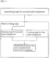
- the heating temperature (first temperature T 1 ) of the second steel component 12 in the shrink-fitting step as illustrated in FIG. 1 is the first temperature T 1 that is equal to or higher than the tempering temperature T 0 of the second steel component 12 and higher than the temperature of the first steel component 11 by the temperature difference ⁇ T for achieving the shrink fitting.
- the temperature difference ⁇ T for achieving the shrink fitting between the first steel component 11 and the second steel component 12 depends on the predetermined fitting dimensions of the outer diameter dimension of the first steel component 11 and the inner diameter dimension of the first holes.
- FIG. 4 is a graph illustrating a temperature condition for the first steel component 11 and the second steel component 12 to be heat-treated in the present embodiment.
- the first steel component 11 is shrink-fitted in the first holes 123 and 124 of the second steel component 12.
- a time t1 illustrated in FIG. 4 is provided to ensure the tempering time. It is preferred to perform the shrink fitting immediately after heating the second steel component 12 to the first temperature T 1 and cooling the first steel component 11 to the second temperature T 2 , but it may often be difficult to do so in an actual line. It is therefore preferred to maintain each of the temperatures T 1 and T 2 until the shrink fitting so that the temperature difference ⁇ T can be ensured at least during the shrink fitting.
- FIG. 3 is a side view illustrating an example in which the process flow illustrated in FIG. 1 is developed as an actual line.
- a heating furnace 21 for the second steel components 12, a heat-retaining furnace 22 and a conveying apparatus 24 for the second steel components 12, a cooling bath 23 and a shrink-fitting apparatus 26 for the first steel components 11, and a conveying apparatus 25 for the third components 13 are arranged in this order from the right side of the figure.
- the heat-retaining furnace 22 for the second steel components 12, which is a tunnel-like furnace covered with a heating insulating material, for example, maintains the second steel components 12 at the first temperature T 1 or a temperature slightly lower than the first temperature T 1 and ensures the tempering time for the second steel components 12 through ensuring the time t1 required for the second steel components 12 to be conveyed to the shrink-fitting step by the conveying apparatus 24.
- the cooling bath 23 for the first steel components 11 is filled with liquid nitrogen 27, for example, and the first steel components 11 are immersed in the liquid nitrogen 27 thereby to be cooled to the second temperature T 2 .
- the conveying apparatus 25 conveys the third components 13 to the shrink-fitting step.
- the shrink-fitting apparatus 26 (including a robot (not illustrated)) operates to insert each third component 13 between the pair of wall parts of each second steel component 12 while grasping the first steel component 11, second steel component 12, and third component 13 and insert the first steel component 11 in the second hole 131 when shrink-fitting the first steel component 11 in the first holes 123 and 124 of the second steel component 12.
- the fitted component 1 thus assembled is delivered to the next step by a conveying apparatus (not illustrated).
- FIG. 5 is a graph obtained by evaluating the surface condition of the heat-treated and assembled component in the present embodiment.
- “Example” represents the result of measurement in which the first steel component 11 was cut out from the fitted component 1 assembled in the heat treatment step as illustrated in FIG. 1 and the friction resistance of the coating 111 portion of the first steel component 11 was measured using a vibration frictional wear tester.
- “Comparative Example” represents the result of measurement in which the second steel component 12 was subjected to a tempering treatment of 180°C ⁇ 70 min instead of the tempering step illustrated in FIG. 1 and the first steel component 11 was press-fitted into the second steel component 12.
- the friction resistance of the coating 111 of the first steel component 11 in “Example” is apparently smaller than that in “Comparative Example.”
- FIG. 6 is a set of photomicrographs obtained by evaluating the surface condition of the heat-treated and assembled component in the present embodiment when observing the surfaces of "Example” and “Comparative Example” produced for the measurement illustrated in FIG. 5 .
- “Comparative Example” streaks and delamination (portion marked with the oval) were observed on the surface, but in “Example,” no streaks and delamination were observed on the surface.
- the first steel component 11 is shrink-fitted in the first holes 123 and 124 of the second steel component 12 in a state of maintaining the temperature difference ⁇ T for achieving the shrink fitting between the first steel component 11 and the second steel component 12 and gaps are therefore formed between the first steel component 11 and the first holes 123 and 124.
- the tempering treatment can be performed without providing a dedicated tempering step because, for the shrink fitting, the second steel component 12 is heated to a temperature equal to or higher than the tempering temperature T 0 . As a result, both the wear resistance and the impact strength of the second steel component 12 can be improved.
- the first steel component 11 is cooled to the second temperature T 2 to ensure the temperature difference ⁇ T for achieving the shrink fitting between the first steel component 11 and the second steel component 12. Therefore, even under the fitting condition in which the temperature difference ⁇ T is large, the heat treatment can be performed without heating the second steel component 12 to the A 1 transformation temperature of 730°C.
- the first steel component 11 is cooled to the second temperature T 2
- the first steel component 11 is carried to the shrink-fitting step while keeping the temperature of the first steel component 11
- the second steel component 12 is carried to the shrink-fitting step while keeping the temperature of the second steel component 12. This can ensure the temperature difference ⁇ T for achieving the shrink fitting and can also ensure the tempering time.
Landscapes
- Engineering & Computer Science (AREA)
- General Engineering & Computer Science (AREA)
- Mechanical Engineering (AREA)
- Automatic Assembly (AREA)
- Heat Treatment Of Articles (AREA)
Abstract
Description
- The present invention relates to a heat treatment method and an assembly method for a fitted component.
- In a conventional technique of press-fitting a stainless steel adjust pipe of a fuel injection valve into a stainless steel stator iron core, it has been known that a chemical conversion coating having lubricity is formed on each of the inner and outer circumferential surfaces of the adjust pipe to reduce the variation in the press-fitting load (Patent Document 1:
JP3791591B - [Patent Document 1]
JP3791591B - However, when a component formed with a coating thereon as in the above conventional technique is press-fitted into a hole of a steel material that is hardened by quenching, the coating may delaminate from the component. The lubricative chemical conversion coating of the above conventional technique achieves its purpose at the time of press-fitting, so the delamination may not be problematic, but if the coating applied to a press-fitted component functions after the press fitting, the delamination may be problematic.
- A problem to be solved by the present invention is to provide a heat treatment method and an assembly method for a fitted component with which when a component formed with a coating thereon is fitted in a quenched component, delamination of the coating can be suppressed.
- The present invention solves the above problem in the following manner. When a first steel component formed with a coating thereon is fitted in a first hole of a second steel component subjected to a quenching treatment, the second steel component is heated to a first temperature equal to or higher than a tempering temperature of the second steel component and equal to or higher than a temperature of the first steel component by a temperature difference for achieving shrink fitting, and the first steel component is shrink-fitted in the first hole of the second steel component in a state of maintaining a temperature difference for achieving shrink fitting between the first steel component and the second steel component.
- According to the present invention, the first steel component is shrink-fitted in the first hole of the second steel component in a state of maintaining the temperature difference for achieving the shrink fitting between the first steel component and the second steel component and it is therefore possible to suppress the delamination of the coating formed on the first steel component. In addition to this, the tempering treatment can be performed without providing a dedicated tempering step because, for the shrink fitting, the second steel component is heated to a temperature equal to or higher than the tempering temperature.
-
-
FIG. 1 is a process flow diagram illustrating an embodiment of a heat treatment method and an assembly method for a fitted component according to the present invention. -
FIG. 2A is a perspective view (before assembly) illustrating an embodiment of a fitted component according to the present invention. -
FIG. 2B is a central cross-sectional view (before assembly) illustrating an embodiment of the fitted component according to the present invention. -
FIG. 2C is a central cross-sectional view (after assembly) illustrating an embodiment of the fitted component according to the present invention. -
FIG. 3 is a side view of a process representing an embodiment of the heat treatment method and assembly method for a fitted component according to the present invention. -
FIG. 4 is a graph illustrating a temperature condition for components to be heat-treated in an embodiment of the heat treatment method and assembly method for a fitted component according to the present invention. -
FIG. 5 is a graph obtained by evaluating the surface condition of the heat-treated and assembled component in the embodiment ofFIGS. 1 to 4 . -
FIG. 6 is a set of photomicrographs obtained by evaluating the surface condition of the heat-treated and assembled component in the embodiment ofFIGS. 1 to 4 . - Hereinafter, one or more embodiments of the present invention will be described with reference to the drawings. According to a first aspect, the present invention provides a heat treatment method for a fitted component, and according to a second aspect, the present invention provides an assembly method for a fitted component. In the following embodiment, the present invention will be described as a heat treatment method for a fitted component, but this embodiment is also applicable to an assembly method for a fitted component.
-
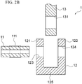
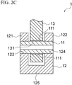
FIG. 2A is a perspective view (before assembly) illustrating an embodiment of a fitted component according to the present invention,FIG. 2B is a central cross-sectional view of the same (before assembly), andFIG. 2C is a central cross-sectional view of the same (after assembly). As illustrated inFIGS. 2A to 2C , the fitted component as an object of the heat treatment method or assembly method in the present embodiment comprises at least afirst steel component 11, asecond steel component 12, and athird component 13. It should be noted, however, that the third component is not an essential component in the fitted component according to the present invention. - The
first steel component 11 is a hollow steel component (or may also be a solid steel component). To reduce the sliding resistance, for example, thefirst steel component 11 is formed with acoating 111, such as a diamond-like carbon film (DLC film), within an area of the outer surface to be in sliding contact with asecond hole 131 of thethird component 13. As illustrated inFIGS. 2B and2C , thefirst steel component 11 is fitted in a pair offirst holes second steel component 12 by shrink fitting and inserted in thesecond hole 131 of the third component. - The
second steel component 12 comprises abase part 125 and a pair ofwall parts base part 125 so as to have a certain space between thewall parts wall parts first holes first steel component 11 is to be fitted. The outer diameter dimension of thefirst steel component 11 and the inner diameter dimension of the first holes are processed to predetermined fitting dimensions. One end part of thethird component 13 is inserted between thewall parts first steel component 11 is inserted in thesecond hole 131 and fitted in thefirst holes third component 13 is thereby pivotably supported with respect to thesecond steel component 12. - One end part of the
third component 13 is formed with the second hole in which thefirst steel component 11 is inserted. Thus, thefirst steel component 11, the second steel component, and thethird component 13 are assembled to constitute a machine element such as a link. - As illustrated in
FIG. 1 , before thesefitting components second steel component 12 is subjected to a quenching treatment. That is, to enhance the wear resistance of thesecond steel component 12 by hardening its component surface, the quenching treatment is performed which includes heating thesecond steel component 12 to a temperature at which the metal structure of the component surface becomes an austenite structure and then rapidly cooling it thereby to generate a hard and dense α-martensite structure. - Then, the
first steel component 11 is fitted in thefirst holes second steel component 12. Here, the surface of thesecond steel component 12 including thefirst holes second steel component 12 has been subjected to the quenching treatment. If, in this state, thefirst steel component 11 is press-fitted into thefirst holes second steel component 12, thecoating 111 such as DLC formed on the surface of thefirst steel component 11 is highly likely to delaminate. Moreover, if a chemical conversion coating having lubricity is formed for the press fitting as in the cited conventional technique, delamination of thecoating 111 can be suppressed, but the coating having lubricity has to be applied to the surface of thefirst steel component 11, so that not only the production cost increases but also the coating having lubricity is removed at the time of press fitting and mixed into thesecond steel component 12 and/or thethird component 13, which may lead to contamination. - On the other hand, the surface of the
second steel component 12 subjected to the quenching treatment is hard and has high wear resistance, but the impact strength (toughness) is low. To achieve both the wear resistance and the impact strength, a tempering treatment may be carried out to keep thesecond steel component 12 at a relatively low temperature of about 150-220°C. In this case, the α-martensite structure can be changed to a β-martensite structure having a relatively low carbon concentration to improve the toughness. However, this reaction requires a long time because the transformation from the α-martensite structure to the β-martensite structure, which occurs in the tempering treatment, is a diffusion and aggregation phenomenon of carbon. Thus, a problem arises in that the treatment time is prolonged. - In the present embodiment, therefore, a dedicated tempering treatment is not performed, and the
first steel component 11 and thesecond steel component 12 are fitted together by shrink fitting rather than press fitting. Then, in consideration of the fact that the shrink fitting requires a temperature difference ΔT between thefirst steel component 11 and thesecond steel component 12, thesecond steel component 12 is heated to a first temperature T1 that is equal to or higher than a tempering temperature T0 of thesecond steel component 12 and higher than a temperature of thefirst steel component 11 by the temperature difference ΔT for achieving the shrink fitting. For example, when the tempering temperature of thesecond steel component 12 is equal to or higher than 150°C (but equal to or lower than an A1 transformation temperature of 730°C), the temperature of thefirst steel component 11 is a room temperature of 20°C, and the temperature difference ΔT required for thesecond steel component 12 to be shrink-fitted with thefirst steel component 11 is 260°C, thesecond steel component 12 is heated to 280°C. When the temperature difference ΔT required for thesecond steel component 12 to be shrink-fitted with thefirst steel component 11 is a large difference such as 340°C, for example, thesecond steel component 12 is heated to 280°C and thefirst steel component 11 is cooled to -50°C. - Thus, the heating temperature (first temperature T1) of the
second steel component 12 in the shrink-fitting step as illustrated inFIG. 1 is the first temperature T1 that is equal to or higher than the tempering temperature T0 of thesecond steel component 12 and higher than the temperature of thefirst steel component 11 by the temperature difference ΔT for achieving the shrink fitting. Here, the temperature difference ΔT for achieving the shrink fitting between thefirst steel component 11 and thesecond steel component 12 depends on the predetermined fitting dimensions of the outer diameter dimension of thefirst steel component 11 and the inner diameter dimension of the first holes. When the temperature difference ΔT is relatively small, therefore, thesecond steel component 12 is heated while thefirst steel component 11 can be in a room temperature state, but when the temperature difference ΔT is large, as illustrated inFIG. 4 , thesecond steel component 12 is heated to the first temperature T1 equal to or higher than the tempering temperature T0 and thefirst steel component 11 is cooled to a second temperature T2 thereby to ensure the temperature difference ΔT for achieving the shrink fitting.FIG. 4 is a graph illustrating a temperature condition for thefirst steel component 11 and thesecond steel component 12 to be heat-treated in the present embodiment. - Then, in a state of maintaining the temperature difference ΔT for achieving the shrink fitting between the
first steel component 11 and thesecond steel component 12, thefirst steel component 11 is shrink-fitted in thefirst holes second steel component 12. In this operation, a time t1 illustrated inFIG. 4 is provided to ensure the tempering time. It is preferred to perform the shrink fitting immediately after heating thesecond steel component 12 to the first temperature T1 and cooling thefirst steel component 11 to the second temperature T2, but it may often be difficult to do so in an actual line. It is therefore preferred to maintain each of the temperatures T1 and T2 until the shrink fitting so that the temperature difference ΔT can be ensured at least during the shrink fitting. -
FIG. 3 is a side view illustrating an example in which the process flow illustrated inFIG. 1 is developed as an actual line. Aheating furnace 21 for thesecond steel components 12, a heat-retainingfurnace 22 and a conveyingapparatus 24 for thesecond steel components 12, a coolingbath 23 and a shrink-fittingapparatus 26 for thefirst steel components 11, and a conveyingapparatus 25 for thethird components 13 are arranged in this order from the right side of the figure. Theheating furnace 21 for thesecond steel components 12, which is a furnace including a high-frequency heating coil, for example, heats thesecond steel components 12 to the first temperature T1. The heat-retainingfurnace 22 for thesecond steel components 12, which is a tunnel-like furnace covered with a heating insulating material, for example, maintains thesecond steel components 12 at the first temperature T1 or a temperature slightly lower than the first temperature T1 and ensures the tempering time for thesecond steel components 12 through ensuring the time t1 required for thesecond steel components 12 to be conveyed to the shrink-fitting step by the conveyingapparatus 24. - The cooling
bath 23 for thefirst steel components 11 is filled withliquid nitrogen 27, for example, and thefirst steel components 11 are immersed in theliquid nitrogen 27 thereby to be cooled to the second temperature T2. The conveyingapparatus 25 conveys thethird components 13 to the shrink-fitting step. Then, in the shrink-fitting step, the shrink-fitting apparatus 26 (including a robot (not illustrated)) operates to insert eachthird component 13 between the pair of wall parts of eachsecond steel component 12 while grasping thefirst steel component 11,second steel component 12, andthird component 13 and insert thefirst steel component 11 in thesecond hole 131 when shrink-fitting thefirst steel component 11 in thefirst holes second steel component 12. The fittedcomponent 1 thus assembled is delivered to the next step by a conveying apparatus (not illustrated). -
FIG. 5 is a graph obtained by evaluating the surface condition of the heat-treated and assembled component in the present embodiment. "Example" represents the result of measurement in which thefirst steel component 11 was cut out from the fittedcomponent 1 assembled in the heat treatment step as illustrated inFIG. 1 and the friction resistance of thecoating 111 portion of thefirst steel component 11 was measured using a vibration frictional wear tester. On the other hand, "Comparative Example" represents the result of measurement in which thesecond steel component 12 was subjected to a tempering treatment of 180°C×70 min instead of the tempering step illustrated inFIG. 1 and thefirst steel component 11 was press-fitted into thesecond steel component 12. The friction resistance of thecoating 111 of thefirst steel component 11 in "Example" is apparently smaller than that in "Comparative Example." -
FIG. 6 is a set of photomicrographs obtained by evaluating the surface condition of the heat-treated and assembled component in the present embodiment when observing the surfaces of "Example" and "Comparative Example" produced for the measurement illustrated inFIG. 5 . In "Comparative Example," streaks and delamination (portion marked with the oval) were observed on the surface, but in "Example," no streaks and delamination were observed on the surface. - As described above, according to the heat treatment method or assembly method for a fitted component of the present embodiment, the
first steel component 11 is shrink-fitted in thefirst holes second steel component 12 in a state of maintaining the temperature difference ΔT for achieving the shrink fitting between thefirst steel component 11 and thesecond steel component 12 and gaps are therefore formed between thefirst steel component 11 and thefirst holes coating 111 formed on thefirst steel component 11 can be suppressed. In addition to this, the tempering treatment can be performed without providing a dedicated tempering step because, for the shrink fitting, thesecond steel component 12 is heated to a temperature equal to or higher than the tempering temperature T0. As a result, both the wear resistance and the impact strength of thesecond steel component 12 can be improved. - Moreover, according to the heat treatment method or assembly method for a fitted component of the present embodiment, the
first steel component 11 is cooled to the second temperature T2 to ensure the temperature difference ΔT for achieving the shrink fitting between thefirst steel component 11 and thesecond steel component 12. Therefore, even under the fitting condition in which the temperature difference ΔT is large, the heat treatment can be performed without heating thesecond steel component 12 to the A1 transformation temperature of 730°C. - Furthermore, according to the heat treatment method or assembly method for a fitted component of the present embodiment, after the
first steel component 11 is cooled to the second temperature T2, thefirst steel component 11 is carried to the shrink-fitting step while keeping the temperature of thefirst steel component 11, and/or after thesecond steel component 12 is heated to the first temperature T1, thesecond steel component 12 is carried to the shrink-fitting step while keeping the temperature of thesecond steel component 12. This can ensure the temperature difference ΔT for achieving the shrink fitting and can also ensure the tempering time. -
- 1
- Fitted component
11 First steel component
111 Coating
12 Second steel component
121, 122 Wall part
123, 124 First hole
125 Base part
13 Third component
131 Second hole - 2
- Shrink-fitting step
21 Heating furnace
22 Heat-retaining furnace
23 Cooling bath
24, 25 Conveying apparatus
26 Shrink-fitting apparatus
27 Liquid nitrogen - T0
- Tempering temperature
- T1
- First temperature
- T2
- Second temperature
- ΔT
- Temperature difference for achieving shrink fitting
Claims (10)
- A heat treatment method for a fitted component wherein a first steel component formed with a coating thereon is fitted in a first hole of a second steel component subjected to a quenching treatment, the heat treatment method comprising:a heating step of heating the second steel component to a first temperature equal to or higher than a tempering temperature of the second steel component, the first temperature being higher than a temperature of the first steel component by a temperature difference for achieving shrink fitting; anda shrink-fitting step of shrink-fitting the first steel component in the first hole in a state of maintaining the temperature difference for achieving shrink fitting between the first steel component and the second steel component.
- The heat treatment method for a fitted component according to claim 1, further comprising
a cooling step of cooling the first steel component to a second temperature in order to obtain the temperature difference for achieving shrink fitting between the first steel component and the second steel component. - The heat treatment method for a fitted component according to claim 2, wherein after the first steel component is cooled to the second temperature, the first steel component is carried to the shrink-fitting step while keeping the temperature of the first steel component.
- The heat treatment method for a fitted component according to any one of claims 1 to 3, wherein after the second steel component is heated to the first temperature, the second steel component is carried to the shrink-fitting step while keeping the temperature of the second steel component.
- The heat treatment method for a fitted component according to any one of claims 1 to 4, wherein the second steel component has a pair of wall parts formed with respective first holes and provided to stand with a space therebetween, and
in the shrink-fitting step, a third component formed with a second hole into which the first steel component is to be inserted is inserted between the pair of wall parts and the first steel component is inserted into the second hole when the first steel component is shrink-fitted in the first holes of the second steel component, wherein the second hole is in sliding contact with the coating. - An assembly method for a fitted component wherein a first steel component formed with a coating thereon is fitted in a first hole of a second steel component subjected to a quenching treatment, the assembly method comprising:a heating step of heating the second steel component to a first temperature equal to or higher than a tempering temperature of the second steel component, the first temperature being higher than a temperature of the first steel component by a temperature difference for achieving shrink fitting; anda shrink-fitting step of shrink-fitting the first steel component in the first hole in a state of maintaining the temperature difference for achieving shrink fitting between the first steel component and the second steel component.
- The assembly method for a fitted component according to claim 6, further comprising
a cooling step of cooling the first steel component to a second temperature in order to obtain the temperature difference for achieving shrink fitting between the first steel component and the second steel component. - The assembly method for a fitted component according to claim 7, wherein after the first steel component is cooled to the second temperature, the first steel component is carried to the shrink-fitting step while keeping the temperature of the first steel component.
- The assembly method for a fitted component according to any one of claims 6 to 8, wherein after the second steel component is heated to the first temperature, the second steel component is carried to the shrink-fitting step while keeping the temperature of the second steel component.
- The assembly method for a fitted component according to any one of claims 6 to 9, wherein the second steel component has a pair of wall parts formed with respective first holes and provided to stand with a space therebetween, and
in the shrink-fitting step, a third component formed with a second hole into which the first steel component is to be inserted is inserted between the pair of wall parts and the first steel component is inserted into the second hole when the first steel component is shrink-fitted in the first holes of the second steel component, wherein the second hole is in sliding contact with the coating.
Applications Claiming Priority (1)
| Application Number | Priority Date | Filing Date | Title |
|---|---|---|---|
| PCT/JP2016/077421 WO2018051484A1 (en) | 2016-09-16 | 2016-09-16 | Heat treatment method and assembly method for fitted component |
Publications (3)
| Publication Number | Publication Date |
|---|---|
| EP3513902A1 true EP3513902A1 (en) | 2019-07-24 |
| EP3513902A4 EP3513902A4 (en) | 2019-10-02 |
| EP3513902B1 EP3513902B1 (en) | 2020-07-22 |
Family
ID=61618697
Family Applications (1)
| Application Number | Title | Priority Date | Filing Date |
|---|---|---|---|
| EP16916265.8A Active EP3513902B1 (en) | 2016-09-16 | 2016-09-16 | Assembly method for fitted component |
Country Status (5)
| Country | Link |
|---|---|
| US (2) | US20190255665A1 (en) |
| EP (1) | EP3513902B1 (en) |
| JP (1) | JP6721052B2 (en) |
| CN (1) | CN109689280B (en) |
| WO (1) | WO2018051484A1 (en) |
Cited By (1)
| Publication number | Priority date | Publication date | Assignee | Title |
|---|---|---|---|---|
| CN111673640A (en) * | 2020-06-17 | 2020-09-18 | 中国原子能科学研究院 | a support device |
Families Citing this family (1)
| Publication number | Priority date | Publication date | Assignee | Title |
|---|---|---|---|---|
| JP6799878B1 (en) * | 2020-06-16 | 2020-12-16 | 松本工業株式会社 | Manufacturing method of joining members |
Family Cites Families (17)
| Publication number | Priority date | Publication date | Assignee | Title |
|---|---|---|---|---|
| JPS59115128A (en) * | 1982-12-23 | 1984-07-03 | Toshiba Corp | Shrink-fitted rotor |
| JPS618232A (en) * | 1984-06-20 | 1986-01-14 | Daido Kogyo Co Ltd | Manufacture of sprocket for bicycles and motor-cycles |
| JPS63185536A (en) * | 1987-01-28 | 1988-08-01 | Kuroki Kogyosho:Kk | Manufacture of double pipe |
| JPS6434614A (en) * | 1987-07-28 | 1989-02-06 | Musashi Seimitsu Kogyo Kk | Ring gear assembly method |
| DK269990A (en) * | 1990-11-12 | 1992-02-12 | Man B & W Diesel Gmbh | CRANK SHAFT FOR A COMBUSTION ENGINE |
| JP3791591B2 (en) * | 2000-11-29 | 2006-06-28 | 株式会社デンソー | Fuel injection valve, adjustment pipe for adjusting spring force thereof, and press-fitting method thereof |
| JP2004090130A (en) * | 2002-08-30 | 2004-03-25 | Mitsubishi Heavy Ind Ltd | JOINING METHOD FOR TiAL-BASE ALLOY AND STEEL PRODUCT |
| US8302833B2 (en) | 2004-04-02 | 2012-11-06 | Black & Decker Inc. | Power take off for cordless nailer |
| DE102007024091A1 (en) * | 2007-05-22 | 2008-11-27 | Mahle International Gmbh | Metallic construction unit tempering and joining method, involves heating of edge zone of construction unit and joining with another construction unit |
| US20120180299A1 (en) * | 2009-07-10 | 2012-07-19 | Progressive Ip Ltd. | Integrity of the union between components |
| US9115554B2 (en) | 2010-11-19 | 2015-08-25 | Baker Hughes Incorporated | Earth-boring tools including replaceable cutting structures and related methods |
| EP2677227B1 (en) | 2012-06-19 | 2015-08-12 | Technip Norge AS | Pipeline with sacrificial anode and method for manufacturing said pipeline |
| DE102012020674A1 (en) * | 2012-10-22 | 2014-04-24 | Volkswagen Aktiengesellschaft | Method for connecting differential cage with driving wheel of axle differential gear box in passenger car, involves performing training process with rotating load, where amplitudes of load lie below rated load torque during process |
| CN104551528A (en) * | 2013-10-21 | 2015-04-29 | 哈尔滨飞机工业集团有限责任公司 | Thermoelectric assembly method of composite blade embedded bushing |
| CN109058484B (en) | 2013-11-26 | 2021-10-15 | S.P.M.流量控制股份有限公司 | Valve seats used in fracturing pumps |
| JP6330358B2 (en) * | 2014-02-12 | 2018-05-30 | 株式会社ジェイテクト | Shrink fit method and shrink fit device |
| US10012318B2 (en) | 2015-03-24 | 2018-07-03 | Parker-Hannifin Corporation | Shuttle valve stabilization through pressure differential and shuttle valve with hollow poppet with weep hole |
-
2016
- 2016-09-16 WO PCT/JP2016/077421 patent/WO2018051484A1/en not_active Ceased
- 2016-09-16 CN CN201680089057.0A patent/CN109689280B/en active Active
- 2016-09-16 JP JP2018539471A patent/JP6721052B2/en active Active
- 2016-09-16 US US16/333,470 patent/US20190255665A1/en not_active Abandoned
- 2016-09-16 EP EP16916265.8A patent/EP3513902B1/en active Active
-
2020
- 2020-03-06 US US16/811,066 patent/US11000924B2/en active Active
Cited By (1)
| Publication number | Priority date | Publication date | Assignee | Title |
|---|---|---|---|---|
| CN111673640A (en) * | 2020-06-17 | 2020-09-18 | 中国原子能科学研究院 | a support device |
Also Published As
| Publication number | Publication date |
|---|---|
| EP3513902B1 (en) | 2020-07-22 |
| CN109689280A (en) | 2019-04-26 |
| US20190255665A1 (en) | 2019-08-22 |
| JP6721052B2 (en) | 2020-07-08 |
| CN109689280B (en) | 2021-03-02 |
| JPWO2018051484A1 (en) | 2019-07-18 |
| WO2018051484A1 (en) | 2018-03-22 |
| EP3513902A4 (en) | 2019-10-02 |
| US20200206850A1 (en) | 2020-07-02 |
| US11000924B2 (en) | 2021-05-11 |
Similar Documents
| Publication | Publication Date | Title |
|---|---|---|
| US11000924B2 (en) | Heat treatment method and assembly method for fitted component | |
| JP2009221593A (en) | Roller follower, valve gear device, high-frequency hardening facility, method for heat-treating shaft member and method for manufacturing shaft, and shaft | |
| US10737354B2 (en) | Bearing component | |
| JP5045491B2 (en) | Large rolling bearing | |
| JP2009197312A (en) | Method for correcting deformation of annular member | |
| CN105209214A (en) | Method of joining two materials by diffusion welding | |
| WO2018012626A1 (en) | Heat treatment method and heat treatment device | |
| CN108884872A (en) | Roller bearing bearing race, the method and roller bearing for manufacturing roller bearing bearing race | |
| CN105263664B (en) | Process for obtaining a mechanical part | |
| JP2010025311A (en) | Rolling bearing and method of manufacturing the same | |
| US10393180B2 (en) | Bearing ring for roller bearing, manufacturing method of bearing ring for roller bearing, and needle roller bearing | |
| JP5433932B2 (en) | Annular deformation correction method | |
| JP6044744B2 (en) | Ball screw device | |
| JP2005113213A (en) | Heat treatment system | |
| JP2016079428A (en) | Heat treatment support | |
| JP2005133214A (en) | Heat treatment system | |
| JP7378201B2 (en) | Manufacturing method of bearing parts | |
| JP2005133212A (en) | Heat treatment system | |
| JP4318999B2 (en) | Heat treatment system | |
| JP2005133215A (en) | Heat treatment system | |
| KR20130094934A (en) | Low strain high frequency induction heat treatment method for linear motion guide manufacturing process | |
| JP2005113210A (en) | Heat treatment system | |
| JP2007321192A (en) | Quenching method of shaft, manufacturing method of shaft having raceway surface | |
| JP2019070176A (en) | Rolling sliding member and method for manufacturing the same and rolling bearing using the rolling sliding member | |
| STEELS | INDUCTION HARDENING |
Legal Events
| Date | Code | Title | Description |
|---|---|---|---|
| STAA | Information on the status of an ep patent application or granted ep patent |
Free format text: STATUS: THE INTERNATIONAL PUBLICATION HAS BEEN MADE |
|
| PUAI | Public reference made under article 153(3) epc to a published international application that has entered the european phase |
Free format text: ORIGINAL CODE: 0009012 |
|
| STAA | Information on the status of an ep patent application or granted ep patent |
Free format text: STATUS: REQUEST FOR EXAMINATION WAS MADE |
|
| 17P | Request for examination filed |
Effective date: 20190308 |
|
| AK | Designated contracting states |
Kind code of ref document: A1 Designated state(s): AL AT BE BG CH CY CZ DE DK EE ES FI FR GB GR HR HU IE IS IT LI LT LU LV MC MK MT NL NO PL PT RO RS SE SI SK SM TR |
|
| AX | Request for extension of the european patent |
Extension state: BA ME |
|
| A4 | Supplementary search report drawn up and despatched |
Effective date: 20190902 |
|
| RIC1 | Information provided on ipc code assigned before grant |
Ipc: F16B 4/00 20060101ALI20190827BHEP Ipc: B23P 11/02 20060101AFI20190827BHEP |
|
| DAV | Request for validation of the european patent (deleted) | ||
| DAX | Request for extension of the european patent (deleted) | ||
| GRAP | Despatch of communication of intention to grant a patent |
Free format text: ORIGINAL CODE: EPIDOSNIGR1 |
|
| STAA | Information on the status of an ep patent application or granted ep patent |
Free format text: STATUS: GRANT OF PATENT IS INTENDED |
|
| RIC1 | Information provided on ipc code assigned before grant |
Ipc: F16C 11/04 20060101ALI20200331BHEP Ipc: F16C 11/02 20060101ALI20200331BHEP Ipc: F16B 4/00 20060101ALI20200331BHEP Ipc: F16D 1/08 20060101ALN20200331BHEP Ipc: B23P 11/02 20060101AFI20200331BHEP |
|
| INTG | Intention to grant announced |
Effective date: 20200421 |
|
| GRAS | Grant fee paid |
Free format text: ORIGINAL CODE: EPIDOSNIGR3 |
|
| GRAA | (expected) grant |
Free format text: ORIGINAL CODE: 0009210 |
|
| STAA | Information on the status of an ep patent application or granted ep patent |
Free format text: STATUS: THE PATENT HAS BEEN GRANTED |
|
| AK | Designated contracting states |
Kind code of ref document: B1 Designated state(s): AL AT BE BG CH CY CZ DE DK EE ES FI FR GB GR HR HU IE IS IT LI LT LU LV MC MK MT NL NO PL PT RO RS SE SI SK SM TR |
|
| REG | Reference to a national code |
Ref country code: GB Ref legal event code: FG4D |
|
| REG | Reference to a national code |
Ref country code: CH Ref legal event code: EP |
|
| REG | Reference to a national code |
Ref country code: DE Ref legal event code: R096 Ref document number: 602016040637 Country of ref document: DE |
|
| REG | Reference to a national code |
Ref country code: AT Ref legal event code: REF Ref document number: 1292963 Country of ref document: AT Kind code of ref document: T Effective date: 20200815 |
|
| REG | Reference to a national code |
Ref country code: IE Ref legal event code: FG4D |
|
| REG | Reference to a national code |
Ref country code: LT Ref legal event code: MG4D |
|
| REG | Reference to a national code |
Ref country code: AT Ref legal event code: MK05 Ref document number: 1292963 Country of ref document: AT Kind code of ref document: T Effective date: 20200722 |
|
| PG25 | Lapsed in a contracting state [announced via postgrant information from national office to epo] |
Ref country code: FI Free format text: LAPSE BECAUSE OF FAILURE TO SUBMIT A TRANSLATION OF THE DESCRIPTION OR TO PAY THE FEE WITHIN THE PRESCRIBED TIME-LIMIT Effective date: 20200722 Ref country code: NO Free format text: LAPSE BECAUSE OF FAILURE TO SUBMIT A TRANSLATION OF THE DESCRIPTION OR TO PAY THE FEE WITHIN THE PRESCRIBED TIME-LIMIT Effective date: 20201022 Ref country code: SE Free format text: LAPSE BECAUSE OF FAILURE TO SUBMIT A TRANSLATION OF THE DESCRIPTION OR TO PAY THE FEE WITHIN THE PRESCRIBED TIME-LIMIT Effective date: 20200722 Ref country code: AT Free format text: LAPSE BECAUSE OF FAILURE TO SUBMIT A TRANSLATION OF THE DESCRIPTION OR TO PAY THE FEE WITHIN THE PRESCRIBED TIME-LIMIT Effective date: 20200722 Ref country code: BG Free format text: LAPSE BECAUSE OF FAILURE TO SUBMIT A TRANSLATION OF THE DESCRIPTION OR TO PAY THE FEE WITHIN THE PRESCRIBED TIME-LIMIT Effective date: 20201022 Ref country code: GR Free format text: LAPSE BECAUSE OF FAILURE TO SUBMIT A TRANSLATION OF THE DESCRIPTION OR TO PAY THE FEE WITHIN THE PRESCRIBED TIME-LIMIT Effective date: 20201023 Ref country code: ES Free format text: LAPSE BECAUSE OF FAILURE TO SUBMIT A TRANSLATION OF THE DESCRIPTION OR TO PAY THE FEE WITHIN THE PRESCRIBED TIME-LIMIT Effective date: 20200722 Ref country code: LT Free format text: LAPSE BECAUSE OF FAILURE TO SUBMIT A TRANSLATION OF THE DESCRIPTION OR TO PAY THE FEE WITHIN THE PRESCRIBED TIME-LIMIT Effective date: 20200722 Ref country code: PT Free format text: LAPSE BECAUSE OF FAILURE TO SUBMIT A TRANSLATION OF THE DESCRIPTION OR TO PAY THE FEE WITHIN THE PRESCRIBED TIME-LIMIT Effective date: 20201123 Ref country code: HR Free format text: LAPSE BECAUSE OF FAILURE TO SUBMIT A TRANSLATION OF THE DESCRIPTION OR TO PAY THE FEE WITHIN THE PRESCRIBED TIME-LIMIT Effective date: 20200722 |
|
| PG25 | Lapsed in a contracting state [announced via postgrant information from national office to epo] |
Ref country code: PL Free format text: LAPSE BECAUSE OF FAILURE TO SUBMIT A TRANSLATION OF THE DESCRIPTION OR TO PAY THE FEE WITHIN THE PRESCRIBED TIME-LIMIT Effective date: 20200722 Ref country code: LV Free format text: LAPSE BECAUSE OF FAILURE TO SUBMIT A TRANSLATION OF THE DESCRIPTION OR TO PAY THE FEE WITHIN THE PRESCRIBED TIME-LIMIT Effective date: 20200722 Ref country code: RS Free format text: LAPSE BECAUSE OF FAILURE TO SUBMIT A TRANSLATION OF THE DESCRIPTION OR TO PAY THE FEE WITHIN THE PRESCRIBED TIME-LIMIT Effective date: 20200722 Ref country code: IS Free format text: LAPSE BECAUSE OF FAILURE TO SUBMIT A TRANSLATION OF THE DESCRIPTION OR TO PAY THE FEE WITHIN THE PRESCRIBED TIME-LIMIT Effective date: 20201122 |
|
| PG25 | Lapsed in a contracting state [announced via postgrant information from national office to epo] |
Ref country code: NL Free format text: LAPSE BECAUSE OF FAILURE TO SUBMIT A TRANSLATION OF THE DESCRIPTION OR TO PAY THE FEE WITHIN THE PRESCRIBED TIME-LIMIT Effective date: 20200722 |
|
| REG | Reference to a national code |
Ref country code: DE Ref legal event code: R097 Ref document number: 602016040637 Country of ref document: DE |
|
| PG25 | Lapsed in a contracting state [announced via postgrant information from national office to epo] |
Ref country code: EE Free format text: LAPSE BECAUSE OF FAILURE TO SUBMIT A TRANSLATION OF THE DESCRIPTION OR TO PAY THE FEE WITHIN THE PRESCRIBED TIME-LIMIT Effective date: 20200722 Ref country code: IT Free format text: LAPSE BECAUSE OF FAILURE TO SUBMIT A TRANSLATION OF THE DESCRIPTION OR TO PAY THE FEE WITHIN THE PRESCRIBED TIME-LIMIT Effective date: 20200722 Ref country code: SM Free format text: LAPSE BECAUSE OF FAILURE TO SUBMIT A TRANSLATION OF THE DESCRIPTION OR TO PAY THE FEE WITHIN THE PRESCRIBED TIME-LIMIT Effective date: 20200722 Ref country code: RO Free format text: LAPSE BECAUSE OF FAILURE TO SUBMIT A TRANSLATION OF THE DESCRIPTION OR TO PAY THE FEE WITHIN THE PRESCRIBED TIME-LIMIT Effective date: 20200722 Ref country code: DK Free format text: LAPSE BECAUSE OF FAILURE TO SUBMIT A TRANSLATION OF THE DESCRIPTION OR TO PAY THE FEE WITHIN THE PRESCRIBED TIME-LIMIT Effective date: 20200722 Ref country code: CZ Free format text: LAPSE BECAUSE OF FAILURE TO SUBMIT A TRANSLATION OF THE DESCRIPTION OR TO PAY THE FEE WITHIN THE PRESCRIBED TIME-LIMIT Effective date: 20200722 |
|
| REG | Reference to a national code |
Ref country code: CH Ref legal event code: PL |
|
| PLBE | No opposition filed within time limit |
Free format text: ORIGINAL CODE: 0009261 |
|
| STAA | Information on the status of an ep patent application or granted ep patent |
Free format text: STATUS: NO OPPOSITION FILED WITHIN TIME LIMIT |
|
| PG25 | Lapsed in a contracting state [announced via postgrant information from national office to epo] |
Ref country code: AL Free format text: LAPSE BECAUSE OF FAILURE TO SUBMIT A TRANSLATION OF THE DESCRIPTION OR TO PAY THE FEE WITHIN THE PRESCRIBED TIME-LIMIT Effective date: 20200722 |
|
| REG | Reference to a national code |
Ref country code: BE Ref legal event code: MM Effective date: 20200930 |
|
| 26N | No opposition filed |
Effective date: 20210423 |
|
| PG25 | Lapsed in a contracting state [announced via postgrant information from national office to epo] |
Ref country code: SK Free format text: LAPSE BECAUSE OF FAILURE TO SUBMIT A TRANSLATION OF THE DESCRIPTION OR TO PAY THE FEE WITHIN THE PRESCRIBED TIME-LIMIT Effective date: 20200722 Ref country code: LU Free format text: LAPSE BECAUSE OF NON-PAYMENT OF DUE FEES Effective date: 20200916 |
|
| PG25 | Lapsed in a contracting state [announced via postgrant information from national office to epo] |
Ref country code: BE Free format text: LAPSE BECAUSE OF NON-PAYMENT OF DUE FEES Effective date: 20200930 Ref country code: CH Free format text: LAPSE BECAUSE OF NON-PAYMENT OF DUE FEES Effective date: 20200930 Ref country code: SI Free format text: LAPSE BECAUSE OF FAILURE TO SUBMIT A TRANSLATION OF THE DESCRIPTION OR TO PAY THE FEE WITHIN THE PRESCRIBED TIME-LIMIT Effective date: 20200722 Ref country code: LI Free format text: LAPSE BECAUSE OF NON-PAYMENT OF DUE FEES Effective date: 20200930 Ref country code: IE Free format text: LAPSE BECAUSE OF NON-PAYMENT OF DUE FEES Effective date: 20200916 |
|
| REG | Reference to a national code |
Ref country code: NL Ref legal event code: MP Effective date: 20200722 |
|
| PG25 | Lapsed in a contracting state [announced via postgrant information from national office to epo] |
Ref country code: TR Free format text: LAPSE BECAUSE OF FAILURE TO SUBMIT A TRANSLATION OF THE DESCRIPTION OR TO PAY THE FEE WITHIN THE PRESCRIBED TIME-LIMIT Effective date: 20200722 Ref country code: MT Free format text: LAPSE BECAUSE OF FAILURE TO SUBMIT A TRANSLATION OF THE DESCRIPTION OR TO PAY THE FEE WITHIN THE PRESCRIBED TIME-LIMIT Effective date: 20200722 Ref country code: CY Free format text: LAPSE BECAUSE OF FAILURE TO SUBMIT A TRANSLATION OF THE DESCRIPTION OR TO PAY THE FEE WITHIN THE PRESCRIBED TIME-LIMIT Effective date: 20200722 |
|
| PG25 | Lapsed in a contracting state [announced via postgrant information from national office to epo] |
Ref country code: MK Free format text: LAPSE BECAUSE OF FAILURE TO SUBMIT A TRANSLATION OF THE DESCRIPTION OR TO PAY THE FEE WITHIN THE PRESCRIBED TIME-LIMIT Effective date: 20200722 Ref country code: MC Free format text: LAPSE BECAUSE OF FAILURE TO SUBMIT A TRANSLATION OF THE DESCRIPTION OR TO PAY THE FEE WITHIN THE PRESCRIBED TIME-LIMIT Effective date: 20200722 |
|
| REG | Reference to a national code |
Ref country code: DE Ref legal event code: R084 Ref document number: 602016040637 Country of ref document: DE |
|
| REG | Reference to a national code |
Ref country code: GB Ref legal event code: 746 Effective date: 20230926 |
|
| PGFP | Annual fee paid to national office [announced via postgrant information from national office to epo] |
Ref country code: DE Payment date: 20250820 Year of fee payment: 10 |
|
| PGFP | Annual fee paid to national office [announced via postgrant information from national office to epo] |
Ref country code: GB Payment date: 20250820 Year of fee payment: 10 |
|
| PGFP | Annual fee paid to national office [announced via postgrant information from national office to epo] |
Ref country code: FR Payment date: 20250820 Year of fee payment: 10 |