EP3513682B1 - Modularer stützfuss zum tragen eines möbelstücks und verfahren zu dessen realisierung - Google Patents
Modularer stützfuss zum tragen eines möbelstücks und verfahren zu dessen realisierung Download PDFInfo
- Publication number
- EP3513682B1 EP3513682B1 EP18198877.5A EP18198877A EP3513682B1 EP 3513682 B1 EP3513682 B1 EP 3513682B1 EP 18198877 A EP18198877 A EP 18198877A EP 3513682 B1 EP3513682 B1 EP 3513682B1
- Authority
- EP
- European Patent Office
- Prior art keywords
- longitudinal
- members
- longitudinal members
- furniture
- item
- Prior art date
- Legal status (The legal status is an assumption and is not a legal conclusion. Google has not performed a legal analysis and makes no representation as to the accuracy of the status listed.)
- Active
Links
Images



Classifications
-
- A—HUMAN NECESSITIES
- A47—FURNITURE; DOMESTIC ARTICLES OR APPLIANCES; COFFEE MILLS; SPICE MILLS; SUCTION CLEANERS IN GENERAL
- A47B—TABLES; DESKS; OFFICE FURNITURE; CABINETS; DRAWERS; GENERAL DETAILS OF FURNITURE
- A47B91/00—Feet for furniture in general
- A47B91/005—Support bases
-
- A—HUMAN NECESSITIES
- A47—FURNITURE; DOMESTIC ARTICLES OR APPLIANCES; COFFEE MILLS; SPICE MILLS; SUCTION CLEANERS IN GENERAL
- A47B—TABLES; DESKS; OFFICE FURNITURE; CABINETS; DRAWERS; GENERAL DETAILS OF FURNITURE
- A47B95/00—Fittings for furniture
- A47B95/002—Plinths, e.g. between furniture and ceiling or wall
-
- A—HUMAN NECESSITIES
- A47—FURNITURE; DOMESTIC ARTICLES OR APPLIANCES; COFFEE MILLS; SPICE MILLS; SUCTION CLEANERS IN GENERAL
- A47B—TABLES; DESKS; OFFICE FURNITURE; CABINETS; DRAWERS; GENERAL DETAILS OF FURNITURE
- A47B95/00—Fittings for furniture
- A47B95/002—Plinths, e.g. between furniture and ceiling or wall
- A47B2095/004—Base plinths
Definitions
- the present invention relates to a modular support base for supporting an item of furniture and method for the realisation thereof.
- the invention relates to a modular support base for column structures (in technical jargon also defined as a "column base”), more precisely furniture for the kitchen, e.g. a fridge.
- the item of furniture into which the household appliance is built comprises a lower base adapted to support the household appliance and the underlying feet to keep the base raised off the floor.
- a lower base adapted to support the household appliance and the underlying feet to keep the base raised off the floor.
- column bases mainly made of plastic material in the form of a quadrilateral with an empty centre or a solid quadrilateral with possible slits.
- These column bases are normally made using moulding or extrusion techniques to obtain a single piece, and therefore a solid base, which is resistant and with few critical points for promoting resistance to loads.
- a first drawback of such structure produced as a single piece is the difficulty to modulate its dimensions for adapting to individual needs which can change over time, such as the place in which it is to be positioned or in the case of replacing the household appliance that the item of furniture has to contain or for adapting to foreign markets where the dimensions of the items of furniture or fridges or the like are different and particular. In fact, in this case, it is necessary to purchase another mould (often expensive) for creating a base with different dimensions.
- Another difficulty is due to the management and transport of the support base as a single piece, i.e. the difficulty encountered in transporting and installing the base at the furniture assembly location.
- the technical task underpinning the present invention is to provide a modular support base of a column structure, prevalently of kitchen furniture such as a fridge, that can obviate the drawback of the prior art mentioned above.
- the object of the present invention is the possibility to obtain a modular product according to different aspects and for each of the components that compose it, so that every user can obtain the most suitable product according to their needs.
- Another object to be obtained is the supply of a modular support base for supporting items of furniture that can be transported more conveniently so as to be able to assemble it directly in situ.
- the present invention is intended for a modular support base for supporting an item of furniture comprising:
- the junction means is also configurable between a coupled condition, wherein the ends of the cross members are connected to the longitudinal members forming a modular support base as a single piece, and an uncoupled condition, wherein the cross members are deconstrained from the longitudinal members therefore the modular base is formed by a plurality of mutually deconstrained components.
- the modular support base for supporting an item of furniture as the main components (at least two longitudinal members and at least two cross members) according to this invention are separate but can be connected with the aid of an interposable fixing means.
- the two longitudinal members and the two cross members are realised separately and therefore the base is not realised as a single piece.
- the longitudinal members have been realised according to the depth requirements of the item of furniture, it is possible to cut the cross members to measure according to the width of the item of furniture before joining them to the longitudinal members.
- each portion of the longitudinal members has at least one lateral projection, in use, facing towards a respective end of a cross member (and towards the other longitudinal member) and each end of the cross members (front and rear) has at least one seat facing the respective portion of the longitudinal member for housing the aforesaid projection.
- each seat is afforded inside the cross member itself according to the extension direction of the cross member. Even more preferably, each seat is defined by the empty space present inside the cross member.
- the projection is preferably realised as a single piece with the related longitudinal member.
- the presence of a projection on a lateral surface of the longitudinal member and a corresponding seat on the respective end of the cross member allows an easy coupling point to be obtained between the components of the modular base in which the junction means can act for completing the connection.
- the junction means in the coupled condition, comprises a mechanical locking system of each seat of the cross members on the respective projection of the longitudinal members.
- the mechanical locking system comprises at least one recess (preferably made by punching) at each end of the cross members directed towards the projection for the formation of the mechanical lock.
- the recess is afforded on the outer surface of the cross member and defines a narrowing of the internal section of the cross member and therefore of the seat in which the projection is inserted. In this way, the projection remains locked inside the respective seat.
- the formation of a mechanical lock confers stability to the structure, not excluding the possibility to change the configuration of the junction means from the coupling condition to the uncoupling condition for the replacement of a component.
- the mechanical lock may be performed through other known techniques.
- the modular base has a resting surface of at least one base of the item of furniture and a surface facing the floor opposite the resting surface, wherein each longitudinal member has a plurality of housings at the surface facing the floor, which are preconfigured for the coupling of different types of bases for feet or feet in different positions. It is to be noted that such housings are defined by holes and/or recesses distanced by predefined distances for a plurality of attachments which are different from each other.
- the cross members front and rear distanced and connected to the longitudinal members form a quadrilateral shaped modular base.
- the central space of the structure which is still free is useful for the recirculation of air in the event that a fridge is positioned, for example.
- At least one longitudinal member comprises, along at least one of its lateral surfaces facing outwards and arranged according to a vertical plane, at least one coupling means in the form of pin elements for coupling with at least one appendage of the item of furniture.
- the longitudinal members have, according to the invention, on their lateral surface, coupling means, in the form of pin elements, for being able to install protective panels that can also provide aesthetic continuity to the structure of the furniture.
- the front portions of said plurality of longitudinal members have a square shape and a reduced thickness for forming a bas-relief with respect to the resting surface of the item of furniture adapted for the installation of a front jig, e.g. a ventilation grille for improving ventilation below the item of furniture when installed.
- a front jig e.g. a ventilation grille for improving ventilation below the item of furniture when installed.
- the plurality of longitudinal members is produced with different materials with respect to the front cross members and the rear cross members.
- the former are made of plastic materials
- the cross members are made of metal materials, e.g. aluminium.
- junction means allows the longitudinal members to be made of a different material from the cross members.
- Longitudinal members and cross members perform different functions, therefore if they are made of different materials they can improve their operation and the related characteristics thereof complement each other.
- longitudinal members made of plastic can be made easily through a same mould or moulds.
- Aluminium cross members guarantee greater resistance and adaptability (an aluminium cross member can be easily cut if the dimensions of the base need to be reduced, for example).
- the method for the realisation of a modular support base for supporting an item of furniture comprises the operating steps of:
- the cross member preparation steps comprise an initial sub-phase in which the cross members are cut to measure according to a pre-chosen width of the base.
- the presence on the lateral surface of the longitudinal members of coupling means, in the form of pin elements, makes it possible to install protective panels that can also provide aesthetic continuity to the structure of the furniture.
- the junction means is configured in a coupling condition through a punching technique.
- the step of preparing a plurality of longitudinal members envisages the use of a plastic material and the step of preparing a front cross member and a rear cross member envisages the use of a different material from said plurality of longitudinal members, preferably a metal material.
- junction means allows the longitudinal members to be made of a different material from the cross members. Longitudinal members and cross members perform different functions, therefore, if they are made of different materials they can improve their operation and related characteristics thereof complement each other, such as lightness, resistance and adaptability (an aluminium cross member can be easily cut if the dimensions of the base need to be reduced, for example).
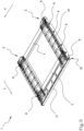
- the present invention relates to a modular support base 1 for supporting items of furniture, specifically to a column base for supporting built-in items of furniture.
- a modular support base 1 for supporting items of furniture according to the present invention is indicated in its entirety by reference number 1.
- Figure 1 illustrates a possible aspect of the modular support base 1 for supporting an item of furniture, which comprises a plurality of longitudinal members 2, at least one front cross member, at least one rear cross member 4 and a junction means 5.
- junction means 5 allows the formation of a single structure that can be used.
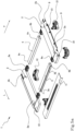
- the longitudinal members 2 are made of plastic material, with moulding or extrusion techniques, for being able to provide for the presence of pin elements for the connection of possible appendages of the item of furniture and for being able to provide for housings 8 of various shapes and sizes for the association of bases for feet or support feet 12 in any position according to the front plinth that is to be installed.
- each longitudinal member 2 may comprise horizontal tabs 13 extending outside the base 1 itself so as to support at least part of the weight of the item of furniture placed above the base 1 (the rest of the weight is however supported by the pin elements).
- Such horizontal tabs 13 are removable for some applications in which the modular base 1 is used to define an intermediate bottom in a position which is more internal with respect to the item of furniture.
- the cross members 3, 4, either front or rear, are a tubular profile with a prevalently square cross section, made of metal material for facilitating the variation of their length according to the variation of the width of the item of furniture to be supported.
- the cross members 3, 4, interposable and connectable to the two portions 2a, 2b of two different longitudinal members 2 with the function of spacers and supports, are generally made of aluminium as they can be easily shortened in length with cutting techniques free from any corrosion phenomena.
- the most commonly used materials are aluminium for the cross members 3, 4 and plastic materials for the longitudinal members 2, however the use of other plastic, ferrous (subjected to suitable anti-corrosion treatments) and wood materials is not excluded, materials which are chosen based on the particular properties which the modular base 1 requires.
- the longitudinal members 2 extend along a longitudinal direction L for a predetermined length and width between two portions 2a, 2b each, a front portion 2a and a rear portion 2b.
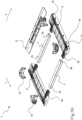
- the front portions 2a of the longitudinal members 2 have a square shape and a narrowing to form bas-reliefs, on which it is possible to install, for example as shown in Figure 4 , a ventilation grille 11 useful for air recirculation for the correct operation of a fridge placed on the modular support base.
- the lateral surface of a longitudinal member facing outwards, when the longitudinal member composes the modular base 1 placed in use, and arranged according to a vertical plane, comprises at least one coupling means 9, in the form of pin elements, useful for the installation of covering and protective lateral panels.
- the lateral surface of the portion of a longitudinal member, front 2a and rear 2b, facing inwards and arranged according to a further vertical plane, has a lateral projection 6a that can be connected with the ends 3a, 4a of the respective cross member 3, 4.
- the cross members, front 3 and rear 4 extend between two ends 3a, 4a along a transverse direction T with respect to the longitudinal length L along which the longitudinal members 2 extend and for a length that is a function of the width of the item of furniture or of a portion of the item of furniture that the modular base 1 has to support.
- the ends 3a, 4a of the cross members 3, 4 have a seat 6b that faces the related portion of the longitudinal member, so that the seat 6b of the end 3a, 4a of the cross member and the lateral projection 6a provided on the longitudinal member are coupled with each other.
- two longitudinal members 2 are arranged on the same plane parallel to each other and at a predetermined distance, to form the opposite sides of a quadrilateral, and coinciding with the length of the cross members 3, 4.
- the two longitudinal members 2 it is possible for the two longitudinal members 2 to be arranged with a mutual angle of inclination comprised between 0° and 90° based on the shape of the item of furniture to be obtained.
- a junction means 5 is required, that can be interposed between the ends 3a, 4a of the cross members 3, 4 and the respective portions 2a, 2b of the longitudinal members 2, which can be configured both in an uncoupled condition, in which the modular base 1 is composed of mutually deconstrained components, and a coupled condition, in which the modular base 1 is formed like a single part.
- the junction means 5 comprises mechanical locking systems 7 such as a screw/bush or, in the case of using the punching technique, at least one recess for each seat 6b of the end 3a, 4a of the cross members 3, 4 directed towards the lateral projection 6a of the respective portion of the longitudinal member, until at least in contact with the latter for creating a friction point able to lock the mutual movement between the parts.
- mechanical locking systems 7 such as a screw/bush or, in the case of using the punching technique, at least one recess for each seat 6b of the end 3a, 4a of the cross members 3, 4 directed towards the lateral projection 6a of the respective portion of the longitudinal member, until at least in contact with the latter for creating a friction point able to lock the mutual movement between the parts.
- the components that describe the modular base 1 are positioned along the sides of a quadrilateral, leaving the centre of the structure free, e.g. for having good air recirculation below the item of furniture, in combination with the ventilation grille 11.
- the modular support base 1 for supporting an item of furniture described above comprises a resting surface for at least one base of the item of furniture and a surface facing the floor opposite said resting surface, as illustrated in figure 2 and in figure 3 .
- the surface facing the floor, at each portion of each longitudinal member, has a plurality of housings 8 of a circular and substantially square shape. These housings 8 are preconfigured for the coupling of different types of bases for feet or feet 12 in different positions, which are able to keep the modular base 1 raised.
- the bases for feet or feet 12 must be arranged at a mutual distance as a function of the front plinth that can be installed to cover the bases for feet and the feet 12 themselves and the space subtended by the modular base 1.
- the bases for feet and the feet 12 currently on the market also have different sizes and shapes that can be installed on the surface facing the floor of the modular base 1 thanks to such housings 8 provided.
- a method for the realisation of a modular support base 1 for supporting an item of furniture is also the subject matter of the present patent, comprising the operating steps of:
- the method described above comprises a further installation sub-step of at least one appendage of the item of furniture, e.g. for covering and protecting the built-in fridge.
- the step of configuring said junction means 5 in the coupling condition may take place through the technique of punching the seat 6b of the cross members 3, 4 towards the projections of the longitudinal members 2.
- the step of preparing a plurality of longitudinal members 2 envisages the use of a plastic material and the step of preparing a front cross member 3 and a rear cross member 4 envisages the use of a different material from said plurality of longitudinal members 2, preferably a metal material, for the combination of the different properties of the materials used.
Landscapes
- Furniture Connections (AREA)
- Assembled Shelves (AREA)
Claims (13)
- Modulare Stützbasis (1) zum Stützen eines Möbelstücks, umfassend:- mindestens zwei Längsträger (2), die in einem vordefinierten Abstand abhängig von einer Breite des Möbelstücks oder eines Teils des Möbels, das abgestützt werden soll, einander zugewandt angeordnet sind; wobei sich ein jeder Längsträger der Vielzahl von Längsträgern entlang einer Längsrichtung (L) zwischen einem vorderen Abschnitt (2a) und einem hinteren Abschnitt (2b) erstreckt;- mindestens einen vorderen Querträger (3), der sich entlang einer Querrichtung (T) in Bezug auf die Längsrichtung (L) zwischen zwei seiner eigenen vorderen Enden (3a) erstreckt; wobei der vordere Querträger (3) zwischen zwei vorderen Abschnitten (2a) von zwei Längsträgern (2) angeordnet ist, die einander zugewandt sind, so dass ein jedes vordere Ende (3a) des vorderen Querträgers (2) mit einem jeweiligen vorderen Abschnitt (2a) der Längsträger (2) verbunden werden kann;- mindestens einen hinteren Querträger (4), der sich entlang einer Querrichtung (T) in Bezug auf die Längsrichtung (L) zwischen zwei seiner eigenen hinteren Enden (4a) erstreckt; wobei der hintere Querträger (4) zwischen zwei hinteren Abschnitten (2b) von zwei Längsträgern (2) angeordnet ist, die einander zugewandt sind, so dass ein jedes hintere Ende (4a) des hinteren Querträgers (4) mit einem jeweiligen hinteren Abschnitt (2b) der Längsträger (2) verbunden werden kann;- Zusammenfügungsmittel (5) zum Zusammenfügen der Querträger (3, 4) mit den Längsträgern (2), wobei die Zusammenfügungsmittel (5) zwischen einem jeden vorderen Ende (3a) des vorderen Querträgers (3) und den jeweiligen vorderen Abschnitten (2a) der Längsträger (2) angeordnet sind; wobei die Zusammenfügungsmittel (5) zwischen einem jeden hinteren Ende (4a) des hinteren Querträgers (4) und den jeweiligen hinteren Abschnitten (2b) der Längsträger (2) angeordnet sind;wobei die Zusammenfügungsmittel (5) zwischen einem gekoppelten Zustand, in dem die Enden (3a, 4a) der Querträger (3, 4) mit den Längsträgern (2), die die modulare Stützbasis (1) bilden, verbunden sind und einem entkoppelten Zustand auslegbar sind, in dem die Querträger (3, 4) von den Längsträgern (2) gelöst sind, so dass die modulare Basis (1) durch eine Vielzahl von gegenseitig gelösten Komponenten gebildet ist;ein jeder Längsträger (2) eine Auflageoberfläche zum Abstützen mindestens einer Basis des Möbelstücks und eine Oberfläche aufweist, die dem der Auflageoberfläche gegenüberliegende Boden zugewandt ist, wobei ein jeder Längsträger (2) an der dem Boden zugewandten Oberfläche mindestens ein Gehäuse (8) aufweist, das für die Ankopplung mindestens einer Basis für einen Fuß oder eines Fußes (12) vorausgelegt ist;dadurch gekennzeichnet, dass mindestens ein Längsträger (2) entlang mindestens einer seiner nach außen weisenden und gemäß einer vertikalen Ebene angeordneten Seitenoberflächen mindestens ein Kopplungsmittel (9) zur Kopplung mit mindestens einem Fortsatz des Möbelstücks umfasst, wobei die Kopplungsmittel Stiftelemente sind.
- Modulare Stützbasis (1) nach Anspruch 1, wobei ein jeder Abschnitt (2a, 2b) der Vielzahl von Längsträgern (2) im Gebrauch mindestens einen seitlichen Vorsprung (6a) aufweist, der einem jeweiligen Ende (3a, 4a) eines Querträgers (3, 4) zugewandt ist;
ein jedes vordere Ende (3a) der vorderen Querträger (3) und ein jedes hintere Ende (4a) der hinteren Querträger (4) mindestens einen Sitz (6b) aufweist, der dem jeweiligen Abschnitt (2a, 2b) des Längsträgers (2) zugewandt ist, um den Vorsprung (6a) des Längsträgers (2) aufzunehmen. - Modulare Basis (1) nach Anspruch 2, wobei die Zusammenfügungsmittel (5) ein mechanisches Verriegelungssystem (7) für einen jeden Sitz (6b) der Querträger (3, 4) an dem jeweiligen Vorsprung (6a) der Längsträger (2) in dem gekoppelten Zustand umfasst.
- Modulare Basis (1) nach Anspruch 3, wobei das mechanische Verriegelungssystem (7) mindestens eine Aussparung an einem jeden Ende (3a, 4a) der Querträger (3, 4) umfasst, die in Richtung des Vorsprungs (6a) zur Bildung der mechanischen Verriegelung gerichtet ist.
- Modulare Basis (1) nach einem der vorhergehenden Ansprüche, dadurch gekennzeichnet, dass ein jedes Längsträger (2) eine Vielzahl von Gehäusen (8) an der dem Boden zugewandten Oberfläche aufweist; wobei die Gehäuse (8) für die Ankopplung verschiedener Arten von Basen für Füße oder Füße (12) in verschiedenen Positionen vorausgelegt sind.
- Modulare Basis (1) nach einem der vorhergehenden Ansprüche, wobei die Querträger (3, 4) während des gekoppelten Zustands voneinander beabstandet sind, um die modulare Basis (1) mit einer viereckigen Form zu bilden.
- Modulare Basis (1) nach einem der vorhergehenden Ansprüche, wobei die vorderen Abschnitte (2a) der Vielzahl von Längsträgern (2) ein Flachrelief (10) aufweisen, das für die Installation einer vorderen Schablone (11) zum Verbessern der Belüftung unter dem Möbelstück angepasst ist, wenn sie installiert ist.
- Modulare Basis (1) nach einem der vorhergehenden Ansprüche, wobei die Vielzahl von Längsträgern (2) mit unterschiedlichen Materialien in Bezug auf die vorderen Querträger (3) und die hinteren Querträger (4) gefertigt ist; wobei die Vielzahl von Längsträgern (2) vorzugsweise aus Kunststoffmaterialien hergestellt ist und die vorderen Querträger (3) und die hinteren Querträger (4) vorzugsweise aus Metallmaterialien hergestellt sind.
- Modulare Basis (1) nach einem der vorhergehenden Ansprüche, dadurch gekennzeichnet, dass sie mindestens einen Fuß umfasst, der mit einem jeweiligen Gehäuse (8) eines jeden Längsträgers (2) verbunden ist, wobei sich der Fuß für eine vordefinierte Höhe von der dem Boden zugewandten Oberfläche wegführend erstreckt, um mindestens die Längsträger (2) und die Querträger (3, 4) vom Boden zu entfernen.
- Verfahren zur Realisierung einer modularen Stützbasis (1) zum Stützen eines Möbelstücks, umfassend die folgenden Arbeitsschritte:a. Vorbereiten einer Vielzahl von Längsträgern (2), die sich entlang einer Längsrichtung (L) für eine bestimmte Länge abhängig von der Tiefe des Möbelstücks erstrecken, wobei ein jeder Längsträger (2) der Vielzahl von Längsträgern einen vorderen Abschnitt (2a) und einen hinteren Abschnitt (2b) aufweist;b. Vorbereiten mindestens eines vorderen Querträgers (3) mit einer bestimmten Länge abhängig von der Breite des Möbelstücks;c. Vorbereiten mindestens eines hinteren Querträgers (4) mit einer bestimmten Länge abhängig von der Breite des Möbelstücks;d. Einfügen des mindestens einen vorderen Querträgers (3) zwischen den vorderen Abschnitten (2a) der Längsträger (2) entlang einer Querrichtung (T) in Bezug auf die Längsrichtung (L) und Verbinden eines jeden vorderen Abschnitts (2a) der Längsträger (2) mit jeweiligen vorderen Enden (3a) des mindestens einen vorderen Querträgers (3) durch Zusammenfügungsmittel (5) ;e. Einfügen des mindestens einen hinteren Querträgers (4) zwischen den hinteren Abschnitten (2b) der Längsträger (2) entlang der Querrichtung (T) in Bezug auf die Längsrichtung (L) und Verbinden eines jeden hinteren Abschnitts (2b) der Längsträger (2) mit jeweiligen hinteren Enden (4a) des mindestens einen hinteren Querträgers (4) durch Zusammenfügungsmittel (5) ;f. Auslegen der Zusammenfügungsmittel (5) im gekoppelten Zustand zur Bildung einer modularen Basis (1) mit einer viereckigen Form;g. Bereitstellen mindestens eines Gehäuses (8) für eine Basis für einen Fuß oder für mindestens einen Fuß (12) an der Vielzahl von Längsträgern (2) auf einer Oberfläche, die der Auflageoberfläche mindestens einer Basis des Möbelstücks gegenüberliegt;dadurch gekennzeichnet, dass es einen Schritt zum Realisieren von mindestens eines Kopplungsmittels (9) umfasst, die entlang der Seitenoberflächen mindestens eines Längsträgers (2) positioniert sind, nach außen weisen und gemäß einer vertikalen Ebene zur Kopplung mit mindestens einem Fortsatz des Möbelstücks angeordnet ist, wobei die Kopplungsmittel Stiftelemente sind.
- Verfahren nach Anspruch 10, dadurch gekennzeichnet, dass es einen Schritt zum Positionieren mindestens einer Basis für einen Fuß oder mindestens eines Fußes (12) auf der Vielzahl von Längsträgern (2) an dem vordefinierten Gehäuse (8) umfasst.
- Verfahren nach einem der Ansprüche 10 bis 11, wobei die Zusammenfügungsmittel (5) in einem gekoppelten Zustand durch eine Stanztechnik ausgelegt sind, die an einem Sitz (6b) eines jeden Querträgers (3, 4) in Bezug auf einen Vorsprung (6a) eines jeden Abschnitts (2a, 2b) eines jeden Längsträgers (2) durchgeführt wird, der innen in den Sitz (6b) eingeführt ist.
- Verfahren nach einem der Ansprüche 10 bis 12, wobei der Schritt zum Vorbereiten einer Vielzahl von Längsträgern (2) die Verwendung eines Kunststoffmaterials vorsieht und der Schritt zum Vorbereiten eines vorderen Querträgers (3) und eines hinteren Querträgers (4) die Verwendung eines Materials verschieden von der Vielzahl von Längsträgern (2), vorzugsweise eines Metallmaterials, vorsieht.
Applications Claiming Priority (1)
| Application Number | Priority Date | Filing Date | Title |
|---|---|---|---|
| IT102017000113692A IT201700113692A1 (it) | 2017-10-10 | 2017-10-10 | Base modulare di supporto di un mobile e relativo metodo di realizzazione |
Publications (2)
| Publication Number | Publication Date |
|---|---|
| EP3513682A1 EP3513682A1 (de) | 2019-07-24 |
| EP3513682B1 true EP3513682B1 (de) | 2024-04-03 |
Family
ID=61148411
Family Applications (1)
| Application Number | Title | Priority Date | Filing Date |
|---|---|---|---|
| EP18198877.5A Active EP3513682B1 (de) | 2017-10-10 | 2018-10-05 | Modularer stützfuss zum tragen eines möbelstücks und verfahren zu dessen realisierung |
Country Status (3)
| Country | Link |
|---|---|
| EP (1) | EP3513682B1 (de) |
| ES (1) | ES2979145T3 (de) |
| IT (1) | IT201700113692A1 (de) |
Citations (4)
| Publication number | Priority date | Publication date | Assignee | Title |
|---|---|---|---|---|
| BE759994A (fr) * | 1970-12-08 | 1971-05-17 | Llull Salort Jose | Base pour appareils electrodomestiques, |
| DE8711284U1 (de) * | 1987-08-20 | 1987-10-01 | Assmann GmbH, 4520 Melle | Möbelsockel |
| DE4342362C1 (de) * | 1993-12-11 | 1995-01-26 | Goldbach Gmbh Holz | Tragestruktur zum Ausrichten eines Möbels, insbesondere für höhenverstellbare Sockel für Einzelschränke und/oder Schränke einer Schrankwand |
| WO1999014131A1 (en) * | 1997-09-16 | 1999-03-25 | Sonoco Development, Inc. | Appliance base pad |
Family Cites Families (2)
| Publication number | Priority date | Publication date | Assignee | Title |
|---|---|---|---|---|
| GB1101461A (en) * | 1963-04-30 | 1968-01-31 | Severard Ltd | Improvements in and relating to support and securing devices for domestic appliances |
| CH449200A (de) * | 1967-06-23 | 1967-12-31 | Forster Ag Hermann | Metallsockel für Küchenmöbel |
-
2017
- 2017-10-10 IT IT102017000113692A patent/IT201700113692A1/it unknown
-
2018
- 2018-10-05 EP EP18198877.5A patent/EP3513682B1/de active Active
- 2018-10-05 ES ES18198877T patent/ES2979145T3/es active Active
Patent Citations (4)
| Publication number | Priority date | Publication date | Assignee | Title |
|---|---|---|---|---|
| BE759994A (fr) * | 1970-12-08 | 1971-05-17 | Llull Salort Jose | Base pour appareils electrodomestiques, |
| DE8711284U1 (de) * | 1987-08-20 | 1987-10-01 | Assmann GmbH, 4520 Melle | Möbelsockel |
| DE4342362C1 (de) * | 1993-12-11 | 1995-01-26 | Goldbach Gmbh Holz | Tragestruktur zum Ausrichten eines Möbels, insbesondere für höhenverstellbare Sockel für Einzelschränke und/oder Schränke einer Schrankwand |
| WO1999014131A1 (en) * | 1997-09-16 | 1999-03-25 | Sonoco Development, Inc. | Appliance base pad |
Also Published As
| Publication number | Publication date |
|---|---|
| EP3513682A1 (de) | 2019-07-24 |
| IT201700113692A1 (it) | 2019-04-10 |
| ES2979145T3 (es) | 2024-09-24 |
Similar Documents
| Publication | Publication Date | Title |
|---|---|---|
| US20100254757A1 (en) | Connector for furniture and method of frame manufacture and assembly | |
| CN110267881B (zh) | 存储平台 | |
| KR101560214B1 (ko) | 조립성이 향상된 프레임 의자 | |
| US20210315381A1 (en) | Improved attachment for furniture feet adjustable in height | |
| US11291301B2 (en) | Modular flat-pack apparatus for customizable cabinetry framing | |
| US20180080489A1 (en) | Furniture assembly bracket, self-assembly furniture using same, and assembly method therefor | |
| EP3513682B1 (de) | Modularer stützfuss zum tragen eines möbelstücks und verfahren zu dessen realisierung | |
| KR20100008790U (ko) | 조립식 랙 선반 | |
| US10201225B2 (en) | Resistant sink base cabinet | |
| KR20220001911U (ko) | 개선된 조립구조를 갖는 물류창고용 랙 구조물 | |
| KR100983131B1 (ko) | 온돌용 패널 어셈블리 구조 | |
| KR20090061167A (ko) | 마감부재를 고정하기 위한 레일지지대가 구비된 붙박이장 | |
| JP2010242365A (ja) | 床材連結金具 | |
| US2477466A (en) | Table top | |
| US20190101330A1 (en) | Two piece base assembly of a dryer | |
| EP1672228A1 (de) | Vorrichtung zum Verbinden von Rahmenteilen | |
| JP7087338B2 (ja) | 家具 | |
| EP1924812B1 (de) | Kühlvorrichtung | |
| JP5213623B2 (ja) | システムキッチンの組立方法およびキャビネット | |
| JP5288604B2 (ja) | システムキッチン | |
| US20130015749A1 (en) | Method for Installing a Side-By-Side Domestic Appliance Combination | |
| KR101545196B1 (ko) | 콘크리트 제품 생산용 보드 | |
| EP1723873A2 (de) | Arbeitsplatte für industrielle Caterings-Küchen | |
| JP6808559B2 (ja) | 足元化粧材の取付構造 | |
| JP6275966B2 (ja) | 畳敷設方法およびこの方法に用いる見切り材 |
Legal Events
| Date | Code | Title | Description |
|---|---|---|---|
| PUAI | Public reference made under article 153(3) epc to a published international application that has entered the european phase |
Free format text: ORIGINAL CODE: 0009012 |
|
| STAA | Information on the status of an ep patent application or granted ep patent |
Free format text: STATUS: THE APPLICATION HAS BEEN PUBLISHED |
|
| AK | Designated contracting states |
Kind code of ref document: A1 Designated state(s): AL AT BE BG CH CY CZ DE DK EE ES FI FR GB GR HR HU IE IS IT LI LT LU LV MC MK MT NL NO PL PT RO RS SE SI SK SM TR |
|
| AX | Request for extension of the european patent |
Extension state: BA ME |
|
| STAA | Information on the status of an ep patent application or granted ep patent |
Free format text: STATUS: REQUEST FOR EXAMINATION WAS MADE |
|
| 17P | Request for examination filed |
Effective date: 20191024 |
|
| RBV | Designated contracting states (corrected) |
Designated state(s): AL AT BE BG CH CY CZ DE DK EE ES FI FR GB GR HR HU IE IS IT LI LT LU LV MC MK MT NL NO PL PT RO RS SE SI SK SM TR |
|
| STAA | Information on the status of an ep patent application or granted ep patent |
Free format text: STATUS: EXAMINATION IS IN PROGRESS |
|
| 17Q | First examination report despatched |
Effective date: 20210119 |
|
| P01 | Opt-out of the competence of the unified patent court (upc) registered |
Effective date: 20230627 |
|
| GRAP | Despatch of communication of intention to grant a patent |
Free format text: ORIGINAL CODE: EPIDOSNIGR1 |
|
| STAA | Information on the status of an ep patent application or granted ep patent |
Free format text: STATUS: GRANT OF PATENT IS INTENDED |
|
| INTG | Intention to grant announced |
Effective date: 20231121 |
|
| GRAS | Grant fee paid |
Free format text: ORIGINAL CODE: EPIDOSNIGR3 |
|
| GRAA | (expected) grant |
Free format text: ORIGINAL CODE: 0009210 |
|
| STAA | Information on the status of an ep patent application or granted ep patent |
Free format text: STATUS: THE PATENT HAS BEEN GRANTED |
|
| AK | Designated contracting states |
Kind code of ref document: B1 Designated state(s): AL AT BE BG CH CY CZ DE DK EE ES FI FR GB GR HR HU IE IS IT LI LT LU LV MC MK MT NL NO PL PT RO RS SE SI SK SM TR |
|
| REG | Reference to a national code |
Ref country code: GB Ref legal event code: FG4D |
|
| REG | Reference to a national code |
Ref country code: CH Ref legal event code: EP |
|
| REG | Reference to a national code |
Ref country code: IE Ref legal event code: FG4D |
|
| REG | Reference to a national code |
Ref country code: DE Ref legal event code: R096 Ref document number: 602018067419 Country of ref document: DE |
|
| REG | Reference to a national code |
Ref country code: LT Ref legal event code: MG9D |
|
| REG | Reference to a national code |
Ref country code: NL Ref legal event code: MP Effective date: 20240403 |
|
| REG | Reference to a national code |
Ref country code: AT Ref legal event code: MK05 Ref document number: 1671270 Country of ref document: AT Kind code of ref document: T Effective date: 20240403 |
|
| PG25 | Lapsed in a contracting state [announced via postgrant information from national office to epo] |
Ref country code: NL Free format text: LAPSE BECAUSE OF FAILURE TO SUBMIT A TRANSLATION OF THE DESCRIPTION OR TO PAY THE FEE WITHIN THE PRESCRIBED TIME-LIMIT Effective date: 20240403 |
|
| REG | Reference to a national code |
Ref country code: ES Ref legal event code: FG2A Ref document number: 2979145 Country of ref document: ES Kind code of ref document: T3 Effective date: 20240924 |
|
| PG25 | Lapsed in a contracting state [announced via postgrant information from national office to epo] |
Ref country code: NL Free format text: LAPSE BECAUSE OF FAILURE TO SUBMIT A TRANSLATION OF THE DESCRIPTION OR TO PAY THE FEE WITHIN THE PRESCRIBED TIME-LIMIT Effective date: 20240403 |
|
| PG25 | Lapsed in a contracting state [announced via postgrant information from national office to epo] |
Ref country code: IS Free format text: LAPSE BECAUSE OF FAILURE TO SUBMIT A TRANSLATION OF THE DESCRIPTION OR TO PAY THE FEE WITHIN THE PRESCRIBED TIME-LIMIT Effective date: 20240803 |
|
| PG25 | Lapsed in a contracting state [announced via postgrant information from national office to epo] |
Ref country code: BG Free format text: LAPSE BECAUSE OF FAILURE TO SUBMIT A TRANSLATION OF THE DESCRIPTION OR TO PAY THE FEE WITHIN THE PRESCRIBED TIME-LIMIT Effective date: 20240403 |
|
| PG25 | Lapsed in a contracting state [announced via postgrant information from national office to epo] |
Ref country code: HR Free format text: LAPSE BECAUSE OF FAILURE TO SUBMIT A TRANSLATION OF THE DESCRIPTION OR TO PAY THE FEE WITHIN THE PRESCRIBED TIME-LIMIT Effective date: 20240403 Ref country code: FI Free format text: LAPSE BECAUSE OF FAILURE TO SUBMIT A TRANSLATION OF THE DESCRIPTION OR TO PAY THE FEE WITHIN THE PRESCRIBED TIME-LIMIT Effective date: 20240403 |
|
| PG25 | Lapsed in a contracting state [announced via postgrant information from national office to epo] |
Ref country code: GR Free format text: LAPSE BECAUSE OF FAILURE TO SUBMIT A TRANSLATION OF THE DESCRIPTION OR TO PAY THE FEE WITHIN THE PRESCRIBED TIME-LIMIT Effective date: 20240704 |
|
| PG25 | Lapsed in a contracting state [announced via postgrant information from national office to epo] |
Ref country code: PT Free format text: LAPSE BECAUSE OF FAILURE TO SUBMIT A TRANSLATION OF THE DESCRIPTION OR TO PAY THE FEE WITHIN THE PRESCRIBED TIME-LIMIT Effective date: 20240805 |
|
| PG25 | Lapsed in a contracting state [announced via postgrant information from national office to epo] |
Ref country code: CZ Free format text: LAPSE BECAUSE OF FAILURE TO SUBMIT A TRANSLATION OF THE DESCRIPTION OR TO PAY THE FEE WITHIN THE PRESCRIBED TIME-LIMIT Effective date: 20240403 |
|
| PG25 | Lapsed in a contracting state [announced via postgrant information from national office to epo] |
Ref country code: AT Free format text: LAPSE BECAUSE OF FAILURE TO SUBMIT A TRANSLATION OF THE DESCRIPTION OR TO PAY THE FEE WITHIN THE PRESCRIBED TIME-LIMIT Effective date: 20240403 |
|
| PG25 | Lapsed in a contracting state [announced via postgrant information from national office to epo] |
Ref country code: PL Free format text: LAPSE BECAUSE OF FAILURE TO SUBMIT A TRANSLATION OF THE DESCRIPTION OR TO PAY THE FEE WITHIN THE PRESCRIBED TIME-LIMIT Effective date: 20240403 |
|
| PG25 | Lapsed in a contracting state [announced via postgrant information from national office to epo] |
Ref country code: LV Free format text: LAPSE BECAUSE OF FAILURE TO SUBMIT A TRANSLATION OF THE DESCRIPTION OR TO PAY THE FEE WITHIN THE PRESCRIBED TIME-LIMIT Effective date: 20240403 |
|
| PG25 | Lapsed in a contracting state [announced via postgrant information from national office to epo] |
Ref country code: PT Free format text: LAPSE BECAUSE OF FAILURE TO SUBMIT A TRANSLATION OF THE DESCRIPTION OR TO PAY THE FEE WITHIN THE PRESCRIBED TIME-LIMIT Effective date: 20240805 Ref country code: PL Free format text: LAPSE BECAUSE OF FAILURE TO SUBMIT A TRANSLATION OF THE DESCRIPTION OR TO PAY THE FEE WITHIN THE PRESCRIBED TIME-LIMIT Effective date: 20240403 Ref country code: NO Free format text: LAPSE BECAUSE OF FAILURE TO SUBMIT A TRANSLATION OF THE DESCRIPTION OR TO PAY THE FEE WITHIN THE PRESCRIBED TIME-LIMIT Effective date: 20240703 Ref country code: LV Free format text: LAPSE BECAUSE OF FAILURE TO SUBMIT A TRANSLATION OF THE DESCRIPTION OR TO PAY THE FEE WITHIN THE PRESCRIBED TIME-LIMIT Effective date: 20240403 Ref country code: IS Free format text: LAPSE BECAUSE OF FAILURE TO SUBMIT A TRANSLATION OF THE DESCRIPTION OR TO PAY THE FEE WITHIN THE PRESCRIBED TIME-LIMIT Effective date: 20240803 Ref country code: HR Free format text: LAPSE BECAUSE OF FAILURE TO SUBMIT A TRANSLATION OF THE DESCRIPTION OR TO PAY THE FEE WITHIN THE PRESCRIBED TIME-LIMIT Effective date: 20240403 Ref country code: GR Free format text: LAPSE BECAUSE OF FAILURE TO SUBMIT A TRANSLATION OF THE DESCRIPTION OR TO PAY THE FEE WITHIN THE PRESCRIBED TIME-LIMIT Effective date: 20240704 Ref country code: FI Free format text: LAPSE BECAUSE OF FAILURE TO SUBMIT A TRANSLATION OF THE DESCRIPTION OR TO PAY THE FEE WITHIN THE PRESCRIBED TIME-LIMIT Effective date: 20240403 Ref country code: CZ Free format text: LAPSE BECAUSE OF FAILURE TO SUBMIT A TRANSLATION OF THE DESCRIPTION OR TO PAY THE FEE WITHIN THE PRESCRIBED TIME-LIMIT Effective date: 20240403 Ref country code: BG Free format text: LAPSE BECAUSE OF FAILURE TO SUBMIT A TRANSLATION OF THE DESCRIPTION OR TO PAY THE FEE WITHIN THE PRESCRIBED TIME-LIMIT Effective date: 20240403 Ref country code: AT Free format text: LAPSE BECAUSE OF FAILURE TO SUBMIT A TRANSLATION OF THE DESCRIPTION OR TO PAY THE FEE WITHIN THE PRESCRIBED TIME-LIMIT Effective date: 20240403 Ref country code: RS Free format text: LAPSE BECAUSE OF FAILURE TO SUBMIT A TRANSLATION OF THE DESCRIPTION OR TO PAY THE FEE WITHIN THE PRESCRIBED TIME-LIMIT Effective date: 20240703 |
|
| REG | Reference to a national code |
Ref country code: DE Ref legal event code: R097 Ref document number: 602018067419 Country of ref document: DE |
|
| PG25 | Lapsed in a contracting state [announced via postgrant information from national office to epo] |
Ref country code: DK Free format text: LAPSE BECAUSE OF FAILURE TO SUBMIT A TRANSLATION OF THE DESCRIPTION OR TO PAY THE FEE WITHIN THE PRESCRIBED TIME-LIMIT Effective date: 20240403 |
|
| PG25 | Lapsed in a contracting state [announced via postgrant information from national office to epo] |
Ref country code: EE Free format text: LAPSE BECAUSE OF FAILURE TO SUBMIT A TRANSLATION OF THE DESCRIPTION OR TO PAY THE FEE WITHIN THE PRESCRIBED TIME-LIMIT Effective date: 20240403 |
|
| PG25 | Lapsed in a contracting state [announced via postgrant information from national office to epo] |
Ref country code: SK Free format text: LAPSE BECAUSE OF FAILURE TO SUBMIT A TRANSLATION OF THE DESCRIPTION OR TO PAY THE FEE WITHIN THE PRESCRIBED TIME-LIMIT Effective date: 20240403 Ref country code: RO Free format text: LAPSE BECAUSE OF FAILURE TO SUBMIT A TRANSLATION OF THE DESCRIPTION OR TO PAY THE FEE WITHIN THE PRESCRIBED TIME-LIMIT Effective date: 20240403 |
|
| PG25 | Lapsed in a contracting state [announced via postgrant information from national office to epo] |
Ref country code: SM Free format text: LAPSE BECAUSE OF FAILURE TO SUBMIT A TRANSLATION OF THE DESCRIPTION OR TO PAY THE FEE WITHIN THE PRESCRIBED TIME-LIMIT Effective date: 20240403 |
|
| PG25 | Lapsed in a contracting state [announced via postgrant information from national office to epo] |
Ref country code: SM Free format text: LAPSE BECAUSE OF FAILURE TO SUBMIT A TRANSLATION OF THE DESCRIPTION OR TO PAY THE FEE WITHIN THE PRESCRIBED TIME-LIMIT Effective date: 20240403 Ref country code: SK Free format text: LAPSE BECAUSE OF FAILURE TO SUBMIT A TRANSLATION OF THE DESCRIPTION OR TO PAY THE FEE WITHIN THE PRESCRIBED TIME-LIMIT Effective date: 20240403 Ref country code: RO Free format text: LAPSE BECAUSE OF FAILURE TO SUBMIT A TRANSLATION OF THE DESCRIPTION OR TO PAY THE FEE WITHIN THE PRESCRIBED TIME-LIMIT Effective date: 20240403 Ref country code: EE Free format text: LAPSE BECAUSE OF FAILURE TO SUBMIT A TRANSLATION OF THE DESCRIPTION OR TO PAY THE FEE WITHIN THE PRESCRIBED TIME-LIMIT Effective date: 20240403 Ref country code: DK Free format text: LAPSE BECAUSE OF FAILURE TO SUBMIT A TRANSLATION OF THE DESCRIPTION OR TO PAY THE FEE WITHIN THE PRESCRIBED TIME-LIMIT Effective date: 20240403 |
|
| PLBE | No opposition filed within time limit |
Free format text: ORIGINAL CODE: 0009261 |
|
| STAA | Information on the status of an ep patent application or granted ep patent |
Free format text: STATUS: NO OPPOSITION FILED WITHIN TIME LIMIT |
|
| 26N | No opposition filed |
Effective date: 20250106 |
|
| PG25 | Lapsed in a contracting state [announced via postgrant information from national office to epo] |
Ref country code: SI Free format text: LAPSE BECAUSE OF FAILURE TO SUBMIT A TRANSLATION OF THE DESCRIPTION OR TO PAY THE FEE WITHIN THE PRESCRIBED TIME-LIMIT Effective date: 20240403 |
|
| REG | Reference to a national code |
Ref country code: CH Ref legal event code: PL |
|
| PG25 | Lapsed in a contracting state [announced via postgrant information from national office to epo] |
Ref country code: MC Free format text: LAPSE BECAUSE OF FAILURE TO SUBMIT A TRANSLATION OF THE DESCRIPTION OR TO PAY THE FEE WITHIN THE PRESCRIBED TIME-LIMIT Effective date: 20240403 |
|
| PG25 | Lapsed in a contracting state [announced via postgrant information from national office to epo] |
Ref country code: LU Free format text: LAPSE BECAUSE OF NON-PAYMENT OF DUE FEES Effective date: 20241005 Ref country code: BE Free format text: LAPSE BECAUSE OF NON-PAYMENT OF DUE FEES Effective date: 20241031 |
|
| PG25 | Lapsed in a contracting state [announced via postgrant information from national office to epo] |
Ref country code: CH Free format text: LAPSE BECAUSE OF NON-PAYMENT OF DUE FEES Effective date: 20241031 |
|
| REG | Reference to a national code |
Ref country code: BE Ref legal event code: MM Effective date: 20241031 |
|
| PG25 | Lapsed in a contracting state [announced via postgrant information from national office to epo] |
Ref country code: SE Free format text: LAPSE BECAUSE OF FAILURE TO SUBMIT A TRANSLATION OF THE DESCRIPTION OR TO PAY THE FEE WITHIN THE PRESCRIBED TIME-LIMIT Effective date: 20240403 |
|
| PG25 | Lapsed in a contracting state [announced via postgrant information from national office to epo] |
Ref country code: IE Free format text: LAPSE BECAUSE OF NON-PAYMENT OF DUE FEES Effective date: 20241005 |
|
| PGFP | Annual fee paid to national office [announced via postgrant information from national office to epo] |
Ref country code: DE Payment date: 20251028 Year of fee payment: 8 |
|
| PGFP | Annual fee paid to national office [announced via postgrant information from national office to epo] |
Ref country code: GB Payment date: 20251023 Year of fee payment: 8 |
|
| PGFP | Annual fee paid to national office [announced via postgrant information from national office to epo] |
Ref country code: IT Payment date: 20251028 Year of fee payment: 8 |
|
| PGFP | Annual fee paid to national office [announced via postgrant information from national office to epo] |
Ref country code: FR Payment date: 20251027 Year of fee payment: 8 |
|
| PG25 | Lapsed in a contracting state [announced via postgrant information from national office to epo] |
Ref country code: CY Free format text: LAPSE BECAUSE OF FAILURE TO SUBMIT A TRANSLATION OF THE DESCRIPTION OR TO PAY THE FEE WITHIN THE PRESCRIBED TIME-LIMIT; INVALID AB INITIO Effective date: 20181005 |
|
| PGFP | Annual fee paid to national office [announced via postgrant information from national office to epo] |
Ref country code: ES Payment date: 20251118 Year of fee payment: 8 |
|
| PG25 | Lapsed in a contracting state [announced via postgrant information from national office to epo] |
Ref country code: HU Free format text: LAPSE BECAUSE OF FAILURE TO SUBMIT A TRANSLATION OF THE DESCRIPTION OR TO PAY THE FEE WITHIN THE PRESCRIBED TIME-LIMIT; INVALID AB INITIO Effective date: 20181005 |