EP3513624B1 - Vorrichtung zum entfernen von dellen - Google Patents
Vorrichtung zum entfernen von dellen Download PDFInfo
- Publication number
- EP3513624B1 EP3513624B1 EP17767781.2A EP17767781A EP3513624B1 EP 3513624 B1 EP3513624 B1 EP 3513624B1 EP 17767781 A EP17767781 A EP 17767781A EP 3513624 B1 EP3513624 B1 EP 3513624B1
- Authority
- EP
- European Patent Office
- Prior art keywords
- leg
- sheet metal
- working head
- metal structure
- free end
- Prior art date
- Legal status (The legal status is an assumption and is not a legal conclusion. Google has not performed a legal analysis and makes no representation as to the accuracy of the status listed.)
- Active
Links
Images

Classifications
-
- B—PERFORMING OPERATIONS; TRANSPORTING
- B21—MECHANICAL METAL-WORKING WITHOUT ESSENTIALLY REMOVING MATERIAL; PUNCHING METAL
- B21D—WORKING OR PROCESSING OF SHEET METAL OR METAL TUBES, RODS OR PROFILES WITHOUT ESSENTIALLY REMOVING MATERIAL; PUNCHING METAL
- B21D1/00—Straightening, restoring form or removing local distortions of sheet metal or specific articles made therefrom; Stretching sheet metal combined with rolling
- B21D1/06—Removing local distortions
-
- H—ELECTRICITY
- H05—ELECTRIC TECHNIQUES NOT OTHERWISE PROVIDED FOR
- H05B—ELECTRIC HEATING; ELECTRIC LIGHT SOURCES NOT OTHERWISE PROVIDED FOR; CIRCUIT ARRANGEMENTS FOR ELECTRIC LIGHT SOURCES, IN GENERAL
- H05B6/00—Heating by electric, magnetic or electromagnetic fields
- H05B6/02—Induction heating
- H05B6/06—Control, e.g. of temperature, of power
-
- H—ELECTRICITY
- H05—ELECTRIC TECHNIQUES NOT OTHERWISE PROVIDED FOR
- H05B—ELECTRIC HEATING; ELECTRIC LIGHT SOURCES NOT OTHERWISE PROVIDED FOR; CIRCUIT ARRANGEMENTS FOR ELECTRIC LIGHT SOURCES, IN GENERAL
- H05B6/00—Heating by electric, magnetic or electromagnetic fields
- H05B6/02—Induction heating
- H05B6/10—Induction heating apparatus, other than furnaces, for specific applications
- H05B6/101—Induction heating apparatus, other than furnaces, for specific applications for local heating of metal pieces
-
- H—ELECTRICITY
- H05—ELECTRIC TECHNIQUES NOT OTHERWISE PROVIDED FOR
- H05B—ELECTRIC HEATING; ELECTRIC LIGHT SOURCES NOT OTHERWISE PROVIDED FOR; CIRCUIT ARRANGEMENTS FOR ELECTRIC LIGHT SOURCES, IN GENERAL
- H05B6/00—Heating by electric, magnetic or electromagnetic fields
- H05B6/02—Induction heating
- H05B6/10—Induction heating apparatus, other than furnaces, for specific applications
- H05B6/14—Tools, e.g. nozzles, rollers, calenders
-
- H—ELECTRICITY
- H05—ELECTRIC TECHNIQUES NOT OTHERWISE PROVIDED FOR
- H05B—ELECTRIC HEATING; ELECTRIC LIGHT SOURCES NOT OTHERWISE PROVIDED FOR; CIRCUIT ARRANGEMENTS FOR ELECTRIC LIGHT SOURCES, IN GENERAL
- H05B6/00—Heating by electric, magnetic or electromagnetic fields
- H05B6/02—Induction heating
- H05B6/36—Coil arrangements
- H05B6/365—Coil arrangements using supplementary conductive or ferromagnetic pieces
Definitions
- the present invention relates to a device for removing dents from sheet metal structures, in particular for removing dents from non-ferromagnetic sheet metal structures by means of inductive heating.
- WO 01/10579 A1 in the name of Advanced Photonics Technologies AG was published on 15 February 2001 and discloses a method and device for removing a dent from sheet metal parts. Therefore, a sheet metal part is locally heated by a lamp. The heating takes place in an essentially contactless manner with the aim of causing a mechanical stress gradient which effects the dent to straighten back.
- the document also discloses applying heat by means of inductive means or by a directed stream of hot air.
- the device described in detail in this application comprises a hood with a lamp and a reflector.
- WO 2006/119661 A1 in the name of Ralph Meichtry was published on 16 November 2006 and discloses a method and a device for removing dents from sheet metal structures based on electromagnetic energy.
- the device comprises a working head which can be interconnected to a power device by a connecting cable.
- the working head is positioned in the area to be treated and brought into contact with the sheet metal.
- a magnetic field is applied by the working head, which effects a magnetic force on the sheet metal, leading to deformation of the dent.
- the device is suited for removing dents from ferromagnetic sheet metal structures.
- WO 2016/020071 A1 in the name of Ralph Meichtry was published on 11 February 2016.
- the document discloses a system to remove dents from ferromagnetic sheet metal structure by local inductive heating, caused by alternating magnetic fields and thereto related local thermal expansion.
- the system disclosed is particularly suited to remove dents from ferromagnetic sheet metal structures in a precise and user-friendly way.
- WO 2016/115514 A1 in the name of Oleg Fishman was published on 21 July 2016 .
- the document relates generally to devices for induction heating and melting of magnetically coupled electrically conductive material inserted into an induction coil.
- current control series resonant power supplies and precise measurement of the power delivered into a magnetically coupled electrically conductive load are disclosed.
- a control circuit is configured to a) adjust an inverter frequency to assure that the inverter always operates at resonance condition, b) adjusts the DC voltage across to the voltage fed inverter to assure that the delivered power to the inductive load is equal to a preset value.
- the systems known comprise several drawbacks. Heating by radiation - such as by means of lamps -may cause thermal damage to the surfaces which absorb the radiation (e.g. coats of varnish) before the underlying sheet metal is sufficiently heated.
- the systems using magnetic fields in order to effect magnetic forces on the sheet metal structures can only be applied to ferromagnetic metals and fail if used for non-ferromagnetic metals. The same holds true for systems using conventional inductive means which work properly when used for ferromagnetic materials but fail when used for non-ferromagnetic metals.
- Non-ferromagnetic metals include aluminum, magnesium, titanium and copper. However, the invention is not limited to be used for these metals. Within the context of the present invention, “aluminum”, “magnesium”, “titanium” and “copper” should be understood as meaning also their alloys.
- Hysteresis loss The main effect responsible for conventional inductive heating of ferromagnetic sheet metal structures is Hysteresis loss which is caused by the alternating magnetic fields. Hysteresis loss allows highly efficient and spatially concentrated heating of most ferromagnetic metals up to their specific Currie temperature. In non-ferromagnetic materials (respectively non-ferrous materials, such as aluminum) heating by Hysteresis loss is not possible. In these materials heating is mostly induced by means of eddy currents. However, many non-iron based alloys (such as aluminum) have a significantly lower electrical resistance than most iron-based alloys. In addition, as these alloys are non-ferromagnetic, they show a larger skin depth.
- aluminum has a relatively high thermal conductivity if compared to e.g. most iron-based alloys.
- heat generated in aluminum is spatially distributed relatively efficiently, leading to large-area thermal expansion and hence low mechanical stress gradients in the region of a dent to be straightened. Consequently straightening of the dent will not take place.
- induction of high currents in sheet metal structures made form non-iron based materials in many cases also fails because the resonance frequency of a resonant circuit arrangement built by a magnetic field generator and the sheet metal structure depends on the dissipation resistance of the sheet metal structure, which itself strongly depends on the geometry of the sheet metal, respectively a dent present in the sheet metal structure.
- induction of high eddy currents fails due to detuning effects.
- the method, device and working head as described herein are particularly suitable for dent removal in sheet metal structures made from non-ferromagnetic materials, such as aluminum, but may also be used for other materials (including ferromagnetic materials).
- the present invention may also be used in order to heat a (ferromagnetic as well as non-ferromagnetic) sheet metal structure locally, e.g. in order to remove a sticker attached to its surface and/or to loosen or break an adhesive connection.
- the invention asdescribed herein may also be used in order to treat sheet metal structures (ferromagnetic as well as non-ferromagnetic) which comprise certain types of coats of varnish that are sensitive to heat and/or comprise components that are sensitive to alternating magnetic fields.
- the invention is herein described mainly for being used with sheet metal structures.
- sheet metal structures although in particular being highly suitable for sheet metal structures, it is not limited to sheet structures and may also be used in order to induce heating in other types of structures.
- a magnetic field generator is provided
- the magnetic field generator is positioned adjacent to the sheet metal structure in the area to be treated (respectively heated) such that it forms a resonance circuit arrangement together with the sheet metal structure.
- at least one calibration current pulse having a specific frequency is applied to the resonance circuit arrangement in order to determine (or at least approximate) the resonance frequency of the resonance circuit arrangement.
- the resonance frequency may be determined based on the frequency response of the resonant circuit arrangement to the calibration current pulse or e.g.
- At least one power current pulse is applied to the resonance circuit arrangement with the operation frequency of the current pulse corresponding to the resonance frequency of the resonance circuit arrangement as determined by the at least one calibration current pulse.
- a current pulse will be formed in order to induce high eddy currents in the sheet metal structure at the area to be treated, whereby a calibration current pulse will be formed in order to prevent induction of high eddy currents. Good results may be obtained if the operation frequency of the current pulse is equal or almost equal to the resonance frequency of the resonance circuit arrangement.
- the device for inducing local heating in a sheet metal structure comprises a power supply unit configured to provide an alternating current. Furthermore, the device comprises a working head with the magnetic field generator for generating a magnetic field. The working head being electrically interconnected with the power supply unit. Moreover, the device comprises a power supply control unit to control operation of the power supply unit. The power supply unit and the working head are interconnect by means of a cable.
- the working head comprises at least one magnetic field generator for generating a magnetic field.
- the magnetic field generator comprises at least one electrical work coil.
- the working head comprises at least one essentially U-shaped core. Said U-shaped core comprises a first and a second leg and a yoke portion. The at least one electrical work coil being interconnected with the U-shaped core.
- the first and the second leg each comprises a free end and a connecting end.
- the connecting ends being arranged at the yoke portion.
- the distance between the free end of the first leg and the free end of the second leg is less than the distance between the connecting end of the first leg and the connecting end of the second leg.
- the working head comprises at least one capacitor.
- the at least one capacitor is arranged in the working head.
- the at least one capacitor being electrically interconnected with the work coil.
- the method allows to account for the fact that the dissipation resistance of a sheet metal structure to be treated depends on multiple factors, including the type of alloy and thickness of the sheet metal structure (which both are not always known), as well as the exact geometry of the area to be treated, which area may have a curvature and/or highly irregular shape/geometry (e.g. in case a dent has to be treated). Thanks to the method highly efficient power transmission to the area to be treated of the sheet metal structure can be obtained, leading to efficient heating. Hence, the method according to the present invention can also be executed using relatively small devices if compared to the conventional methods which can only be executed on relatively large and heavy devices, which usually cannot be formed as handheld devices. Thus user-friendly local heating of sheet metal structures made from non-ferromagnetic materials becomes possible.
- the frequency of the alternating current output provided by e.g. a power supply unit can be tuned precisely to the resonance frequency (or at least sufficiently close to the resonance frequency in order to obtain high eddy currents) of the resonant circuit arrangement.
- maximum power throughput and consequently maximum heating induced in the sheet metal structure can be obtained.
- Precise calibration and efficient induction of heat in a sheet metal structure may be obtained if calibration current pulses and/or power current pulses with an at least approximately sinusoidal (amplitude) modulation (100%) are used.
- Good results may be obtained if a sequence of calibration current pulses is applied to the resonance circuit arrangement in order to determine the resonance frequency of the resonance circuit arrangement. Hence multiple subsequent calibration current pulses (preferably each with a different frequency) may be applied and the resonance frequency e.g. be determined subsequently based on the set of frequency responses for these current pulses. Alternatively or in addition during a calibration current pulse, the operation frequency may sweep from a chosen start frequency to a chosen end frequency. Good results for various types of sheet metal structures made from aluminum may be obtained if the start frequency is about 58 kHz (kilohertz) and the end frequency is about 62 kHz (kilohertz).
- the current pulses of the calibration sequence of current pulses may have frequencies that differ from each other and that are between 58 kHz (kilohertz) and 62 kHz (kilohertz).
- frequencies may be applied.
- Other ranges of frequencies may be applied.
- the calibration sequence of current pulses comprises between 10 and 20 current pulses.
- a precise determination of the resonance frequency of a large group of sheet metal structures may be obtained if the duration of each current pulse of the calibration sequence of current pulses is between 15 ms (milliseconds) and 20 ms (milliseconds).
- a method that can be applied to a large group of sheet metal structures and which can be executed with a relatively simple device uses a sequence of power current pulses that has an envelope of modulation of 50 Hz (hertz) and an operation frequency that is equal to the resonance frequency of the resonant circuit arrangement.
- relatively simple electronic circuits and devices with relatively small outer dimensions and low weight can be applied, in particular if 100% amplitude modulation is applied and power is provided by a mains electricity system with a frequency of 50 Hz.
- envelopes of modulation may be used, such as e.g. 60 Hz (hertz).
- two sequences of power current pulses may be separated by a minimum time period.
- the minimum time period may be controlled/set by a control unit based on measurements of the temperature at the working head and/or at the sheet metal structure. Alternatively or in addition the minimum time period may be set by an operator.
- the number of power current pulses and/or the maximum total duration of the sequence of power current pulses may be preset. This number and/or the duration may be set by an operator and/or may be controlled by a control unit.
- power may be controlled by pulse amplitude modulation and/or by detuning.
- the device for carrying out the method as described herein comprises a power supply unit configured to provide an alternating current and at least one working head with a magnetic field generator for generating a magnetic field, the working head being electrically interconnected with the power supply unit.
- the device also comprise a control unit to control operation of the power supply unit and/or to determine or at least assist in determining the resonance frequency.
- a device with a particularly small size and low weight that is particularly convenient for an operator may be obtained if the power supply unit and the working head are interconnect by means of a cable.
- the working head may be formed as a handheld device.
- the power supply unit may comprise an inverter or a converter.
- a converter may be applied if the power supply unit itself is foreseen to be powered by AC power supply, whereas an inverter may be applied if the power supply unit is to be powered by e.g. a battery.
- the converter is a full-bridge converter, respectively the inverter is a full-bridge inverter.
- the inverter is a full-bridge inverter.
- other types of converters, respectively inverters may be used, such as half-bridge types.
- the operating frequency of the inverter or of the converter may be adjustable in order to tune it to the resonance frequency of the resonance circuit arrangement.
- Efficient heating in e.g. a sheet metal structure made from aluminum may be obtained if the generated alternating current has an operation frequency of between 55 kHz (kilohertz) and 65 kHz (kilohertz), preferably between 58 kHz and 62 kHz.
- the power supply unit, the control unit and the working head are configured such that an impedance matching network with an envelope of modulation of about 50 Hz (hertz) and an operation frequency of about 60 kHz (kilohertz) is obtained.
- the power supply unit and the control unit may be arranged in the same housing.
- the control unit may also be at least partially arranged in the working head or in a separate housing.
- the device may comprise a means to set the specified duration of a power sequence of current pulses and/or the number of current pulses of a power sequence of current pulses and/or the amplitude of modulation. Hence overheating of a sheet metal structure may be prevented.
- the device may comprise a user interface configured to set at least one of these parameters.
- the parameters may also be set based on information regarding the material (e.g. type of alloy) and/or geometry (e.g. thickness) of the sheet metal structure.
- the method may comprise the method step of obtaining at least one method parameter from a database.
- a method parameter may be a preset resonance frequency, a preset number of calibration or power current pulses, a preset duration of a calibration or power current pulse, the type of modulation of a calibration or power current pulse.
- the method may comprise the method step of retrieving a preset resonance frequency from a database, the preset resonance frequency subsequently being used in order to set a frequency for the at least one calibration current pulse.
- a frequency range from a certain frequency below the preset resonance frequency to a value above to preset resonance frequency may be calculated and swept with at least one calibration current pulse (respectively a sequence of multiple calibration current pulses) in order to determine (respectively approximate) the (actual) resonance frequency of the resonance circuit arrangement.
- the preset frequency may be obtained based on data provided to the method. Such data may include information regarding the type of alloy and/or geometry (e.g. the thickness) of the sheet metal structure. If the method is to be used in order to treat a vehicle (e.g. an air, land or water vehicle), at least one method parameter may be retrieved based on the type of vehicle and/or part of the vehicle to be treated.
- a preset resonance frequency may be retrieved from a database by providing a serial number or type designation (e.g. Land Rover Defender 110, 2010 model) and the part to be treated (e.g. hood).
- the method may also comprise the method step of providing information to a database, e.g. method parameters applied to a specific area of a sheet metal structure.
- temperature and/or position and/or motion as measured during a treatment may be provide to a database.
- treatment may be recorded/logged for quality assurance and/or to be retrieved for future treatments on the same type of sheet metal structure.
- a device according to the invention may comprise a database to store method parameters and/or comprise an interface to access a database containing method parameters or other information (e.g.
- the working head for the device as described herein comprises at least one magnetic field generator for generating a magnetic field, comprising at least one electrical work coil and at least one essentially U-shaped core, said core comprising a first and a second leg and a yoke portion, as well as at least one electrical work coil being interconnected with the U-shaped core.
- the first and the second leg each comprise a free end and a connecting end, the connecting end of the first leg and the connecting end of the second leg being arranged at the yoke portion, wherein the distance between the free end of the first leg and the free end of the second leg being less than the distance between the connecting end of the first leg and the connecting end of the second leg.
- the free end of the first leg may comprise a protrusion that protrudes in direction of the free end of the second leg and/or the free and of the second leg comprises a protrusion that protrudes in direction of the free end of the first leg.
- Good results may be obtained if the first and the second end each comprise a protrusion, which protrusions being arranged such that they converge to each other.
- the working head may comprise a housing with at least one working face foreseen to be brought in contact with an area to be treated in a sheet metal structure.
- the working face will be brought in loose contact with a dent; hence no adhesives will be needed in order to establish contact.
- an auxiliary sheet e.g. a fabric or film material
- a working head may comprise a vacuum system arranged to establish a mechanical interconnection (respectively some type of adherence) between the working head and a sheet metal structure to be treated.
- Good results may be obtained if the working head comprises a working face with a vacuum means arranged to obtain a vacuum to a sheet metal structure the working head is brought in contact with.
- alignment of the working head may be improved.
- the vacuum system may be used in order to detect proper alignment, respectively positioning, of the working head on a sheet metal structure to be treated.
- a working head, respectively device may measure air-pressure in a vacuum system in order to trigger a calibration and/or a power current pulse, respectively to prevent initiation of such pulses.
- the vacuum system may be used in order to determine if two subsequent treatments with the method as described herein are applied to the same area of a sheet metal structure or to different areas (respectively if a working head has been moved between the two treatments. This information may be used in order to obtain method parameters as used for the method.
- the method parameters may be reset to initial standard values, whereas they may be adjusted based on the method parameters used in an antecedent treatment if the same area is treated (respectively the working head has not been moved).
- a working head may comprise at least one sensor to measure the temperature of a sheet metal structure to be treated.
- a sensor may e.g. to measure the surface temperature.
- Such as sensor may comprise a contact thermo-sensor and/or a noncontact thermo-sensor (such as a sensor that measures thermal radiation).
- the free end of the first leg and/or the free end of the second leg may comprise an active face configured to align with a sheet metal structure.
- Such an active face may align with a working face of a housing (if present) and/or may form a working face of a housing.
- Particularly high currents induced in a sheet metal structure may be obtained if the area of the active face of the free end of the first leg is smaller than the mean cross-section of the first leg and/or the active face of the free end of the second leg is smaller than the mean cross-section of the second leg.
- the protrusion and/or the legs may be tapered. Good results may be obtained if at least one protrusion is essentially shaped like a frustum.
- the at least one U-shaped core may be integrally made.
- the at least one U-shaped core may be made from at least two bodies.
- the at least one U-shaped core may e.g. be made from three bodies.
- the U-shaped core may also be made e.g. from five bodies, a first body forming a yoke portion, a second body forming a first leg, a third body forming a second leg, as well as two protrusion bodies arranged at the free ends of the first, respectively the second leg forming protrusions. Therefore, the bodies may be mechanically interconnected e.g. by means of a glue.
- U-shaped cores with relatively complex shapes can be obtained relatively easily, based on simple fundamental geometric bodies.
- U-shaped cores with geometries optimized for particular sheet metal structures can be built in an economic way.
- the at least one U-shaped core may be at least partially made from a magnetic powder material in order to withstand particularly high magnetic flux.
- the core is at least partially made from Sendust material.
- the working head may have a working face that comprises a recess for visual control of a heating process (respectively dent removing process).
- a recess may extend persistently across the working face and divide the working face in at least two sections.
- the working head may comprise an illumination device in order to illuminate the area to be treated and/or an adjacent area of a sheet metal structure to be treated.
- visual control of the treatment e.g. dent removal or loosening of an adhesive connection
- the illumination device comprises a LED module and/or a fluorescent lamp and/or a laser.
- the working head comprises a recess as described above, the recess may be illuminated.
- the illumination device may be arranged such that at least one specific pattern can be projected on the sheet metal structure. Thus, e.g. progress/outcome of a dent removal process may be visually monitored very precisely.
- the working head, respectively device may comprise a position detector and/or a motion detector in order to detect/monitor the effect of performing the method as described herein has on the geometry of the sheet metal structure to be treated with it.
- a detector may e.g. comprise a laser rangefinder device and/or an ultrasound module.
- the Doppler shift may be used in order to determine the deformation mode of a dent.
- Information determined with such detectors may be used in order adjust the calibration current pulse and/or the power current pulse and/or to inhibit further current pulses in case the method does not have a certain effect.
- measurements of a position detector and/or a motion detector during the treatment of at least one area of a sheet metal structure may be used in order to adjust at least one calibration current pulse and/or at least one power current pulse of at least one area subsequently to be treated.
- the outcome of treatments can be improved.
- the working head may comprise a cooling system in order to dissipate thermal energy from the magnetic field generator.
- At least one capacitor may be arranged in the working head, the capacitor being electrically interconnected with the work coil in series.
- a resonant circuit arrangement may be formed.
- Good results may be obtained if the at least one capacitor is formed as a capacitor bank.
- the working head may comprise a first and a second capacitor bank, the first and the second capacitor bank being electrically interconnected in series.
- Such an arrangement can withstand high electrical voltage occurring when in resonance.
- cooling of the capacitors can be improved. Further capacitors may be present.
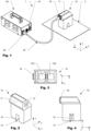
- Figure 1 shows a device 1 for removing dents from a sheet metal structure 2.
- the device 1 comprises a working head 10 and a power supply unit 50, which comprises a power supply control unit 51 that comprises a user interface 52 which allows a user to set certain settings.
- a user/operator may provide the controller with information regarding the sheet metal structure to be processes. This information may include data regarding the material (e.g. type of alloy) as well as geometry (e.g. thickness of a sheet metal structure) as well as data regarding the type of process to be performed (dent removal, local heating).
- the working head 10 comprises a housing 11 and a connector 16 that serves in order to connect the working head 10 to the power supply unit 50 by means of a cable 40.
- FIGS 2, 3 and 4 show the embodiment of a working head 10 of Figure 1 .
- the working head 10 comprises a housing 11 which has a working face 13 to be aligned with a sheet metal structure 2 to which the working head 10 is to be applied.
- the embodiment of a working head 10 shown also comprises an activating means 12, which is essentially a button, by which a process according to invention as described herein can be initiated and/or be stopped.
- the embodiment of a working head 10 shown comprises a recess 14 that is arranged at a bottom portion of the housing 11.
- the recess 14 is arranged approximately in the middle of the working face 13a,b and formed like a groove.
- the recess 14 may comprise chamfers 15 which facilitate visual inspection of the area (e.g. dented region) of the sheet metal structure 2 that is to be treated during application of the method according to the invention as described herein.
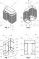
- FIGs 5 and 6 schematically show an embodiment of a U-shaped core 23 comprising a work coil 21 that is spatially divided into two sub-coils, as may be used in an embodiment of a working head 10 as shown in Figures 1 to 4 .
- the U-shaped core 23 comprises a yoke portion 24 and a first and a second leg 25, 26.
- the first and the second leg 25, 26 have both have a free end 27a,b as well as a connecting end 28a,b which is interconnected with the yoke portion 24, as is shown in more detail in Figures 7 and 8 that show the embodiment of a U-shaped core 23 of Figures 5 and 6 when separated from the work coil 21.
- first and the second leg 25, 26 each comprise a protrusion 29a,b arranged at their free ends 27a,b.
- the protrusions 29a,b are arranged such that the distance between the free end 27a of the first leg 25 and the free end 27b of the second leg 26 is less than the distance between the connecting end 28a of the first leg 25 and the connecting 28b end of the second leg26.
- both free ends 27a,b comprise an active face 31a,b configured (respectively shaped) to align with a sheet metal structure (not shown) the method is to be applied to.
- the magnetic field can be focused to the area of the sheet metal structure to be treated and consequently particularly high currents and resulting heating can be obtained.
- the free ends 27a,b (respectively the protrusions 29a,b) of the embodiment shown comprise narrowings 30.
- the areas of the active faces 31a,b (respectively the parts of the effective faces that are in proximity with the sheet metal structure) may be smaller than the mean cross-section of the first and second leg 25, 26.
- the embodiment of a U-shaped core 23 as shown in Figures 5 to 8 is made from five bodies that are mechanically interconnected with each other. Good results may be obtained if the bodies are interconnected by means of an adhesive agent, in particular by means of a heat-resistant adhesive agent.
- a first body forms the yoke portion 24, a second body forms the first leg 25, a third body forms the second leg 26, whereas the protrusions 29a,b are both formed by separate bodies arranged at the free ends 27a,b of the first and the second leg 25, 26.
- the U-shaped core can be assembled based on three bodies that have a relatively simple standardized geometry and two bodies that may be specifically built based on the sheet metal structure and/or application the U-shaped core 23 is to be used for.
- the five bodies of the embodiment shown may be made from a magnetic powder.
- Figures 9 and 10 shown another embodiment of a U-shaped core 23 with and without a work coil 21.
- the U-shaped core is integrally made, hence may e.g. be a machined ferrite core.
- the core may also be made from a magnetic powder, such as by a sintering.
- Figure 11 shows another embodiment of a U-shaped core 23 that is assembled from three different bodies.
- a first body forms the main portion of the U-shaped body and two further bodies arranged at the free ends 27a,b of the first and the second leg 25, 26 of the U-shaped body form protrusions 29a,b.
- Figure 12 shows a U-shaped core 23 with a work coil 21 and a capacitor that comprises two capacitor banks 22a,b which are interconnected with each other and the work coil 21 in series.
Landscapes
- Physics & Mathematics (AREA)
- Electromagnetism (AREA)
- Engineering & Computer Science (AREA)
- Mechanical Engineering (AREA)
- General Induction Heating (AREA)
Claims (16)
- Vorrichtung (1) zum Induzieren einer lokalen Erwärmung in einer Blechstruktur (2) durch ein Verfahren, das die folgenden Verfahrensschritte umfasst:a. Bereitstellen einer Blechstruktur (2), die einen zu erwärmenden Bereich umfasst;b. Bereitstellen eines Magnetfeldgenerators (20);c. Positionieren des Magnetfeldgenerators (20) angrenzend der Blechstruktur (2) in dem zu behandelnden Bereich, so dass dieser zusammen mit der Blechstruktur (2) eine Resonanzkreisanordnung bildet;d. Anlegen mindestens eines Kalibrierstromimpulses mit einer bestimmten Frequenz an die Resonanzkreisanordnung, um die Resonanzfrequenz der Resonanzkreisanordnung zu bestimmen;e. Anlegen mindestens eines Leistungsstromimpulses an die Resonanzkreisanordnung, wobei die Betriebsfrequenz des Stromimpulses der Resonanzfrequenz der Resonanzkreisanordnung entspricht, die durch den mindestens einen Kalibrierstromimpuls bestimmt wurde;wobei die Vorrichtung (1) aufweist:a. eine Stromversorgungseinheit (50), die so konfiguriert ist, um einen Wechselstrom zu liefern;b. einen Arbeitskopf (10) mit dem Magnetfeldgenerator (20) zur Erzeugung eines Magnetfeldes, wobei der Arbeitskopf (10) elektrisch mit der Stromversorgungseinheit (50) verbunden ist;c. eine Stromversorgungssteuereinheit (51) zur Steuerung des Betriebs der Stromversorgungseinheit (50) und zur Durchführung der Schritte d, e des Verfahrens; wobeid. die Stromversorgungseinheit (50) und der Arbeitskopf (10) mittels eines Kabels (40) miteinander verbunden sind; wobeie. der Arbeitskopf (10) umfasst:i. mindestens einen Magnetfeldgenerator (20) zum Erzeugen eines Magnetfeldes, der mindestens eine elektrische Arbeitsspule (21) umfasst;ii. mindestens einen im Wesentlichen U-förmigen Kern (23), wobei der U-förmige Kern (23) einen ersten und einen zweiten Schenkel (25, 26) und einen Jochabschnitt (24) umfasst, wobei die mindestens eine elektrische Arbeitsspule (21) mit dem U-förmigen Kern (23) verbunden ist;iii. der erste und der zweite Schenkel (25, 26) jeweils ein freies Ende (27a,b) und ein Verbindungsende (28a,b) aufweisen, wobei die Verbindungsenden (28a,b) an dem Jochabschnitt (24) angeordnet sind, wobei der Abstand zwischen dem freien Ende (27a) des ersten Schenkels (25) und dem freien Ende (27b) des zweiten Schenkels (26) geringer als der Abstand zwischen dem Verbindungsende (28a) des ersten Schenkels (25) und dem Verbindungsende (28b) des zweiten Schenkels (26) ist; wobeiiv. mindestens ein Kondensator (22a,b) im Arbeitskopf (10) angeordnet ist, wobei der Kondensator (22a,b) elektrisch mit der Arbeitsspule (21) verbunden ist.
- Vorrichtung (1) nach Anspruch 1, wobei die Stromversorgungseinheit (50) einen Wechselrichter oder einen Konverter zur Erzeugung von hochfrequentem Wechselstrom umfasst.
- Vorrichtung (1) nach Anspruch 22, wobei der Konverter ein Vollbrückenkonverter oder der Wechselrichter ein Vollbrückenwechselrichter ist.
- Vorrichtung (1) nach einem der Ansprüche 2 oder 3, wobei die Betriebsfrequenz des Wechselrichters oder des Konverters einstellbar ist, um sie auf die Resonanzfrequenz der Resonanzkreisanordnung abzustimmen.
- Vorrichtung (1) nach einem der vorhergehenden Ansprüche, wobei die Stromversorgungseinheit (50), die Steuereinheit (51) und der Arbeitskopf (10) so konfiguriert sind, um ein Impedanzanpassungsnetzwerk mit einer Modulationshüllkurve von etwa 50 Hz und einer Betriebsfrequenz von etwa 60 kHz zu erhalten.
- Vorrichtung (1) nach einem der vorhergehenden Ansprüche, wobei die Stromversorgungseinheit (50) und die Steuereinheit (51) in demselben Gehäuse angeordnet sind.
- Vorrichtung (1) nach einem der vorhergehenden Ansprüche, wobei die Steuereinheit (51) ein Mittel zum Einstellen der vorgegebenen Dauer einer Leistungssequenz von Stromimpulsen und/oder der Anzahl von Stromimpulsen einer Leistungssequenz von Stromimpulsen aufweist.
- Vorrichtung (1) nach einem der vorhergehenden Ansprüche, wobei das freie Ende (27a) des ersten Schenkels (25) einen Vorsprung (29a) aufweist, der in Richtung des freien Endes (27b) des zweiten Schenkels (26) vorsteht und/oder das freie Ende (27b) des zweiten Schenkels (26) einen Vorsprung (29b) aufweist, der in Richtung des freien Endes (27a) des ersten Schenkels (25) vorsteht.
- Vorrichtung (1) nach einem der vorhergehenden Ansprüche, wobei der Arbeitskopf (10) ein Gehäuse (11) mit mindestens einer Arbeitsfläche (13a,b) aufweist, die dazu vorgesehen ist, mit einem zu bearbeitenden Bereich einer Blechstruktur (2) in Kontakt gebracht zu werden.
- Vorrichtung (1) nach einem der vorhergehenden Ansprüche, wobei das freie Ende (27a) des ersten Schenkels (25) und/oder das freie Ende (27b) des zweiten Schenkels (26) eine aktive Fläche (31a,b) aufweist, die so konfiguriert ist, um sich mit einer Blechstruktur (2) auszurichten.
- Vorrichtung (1) nach Anspruch 10, wobei die Fläche der aktiven Fläche (31a) des freien Endes (27a) des ersten Schenkels (25) kleiner als der mittlere Querschnitt des ersten Schenkels (25) ist und/oder die aktive Fläche (31b) des freien Endes (27b) des zweiten Schenkels (26) kleiner als der mittlere Querschnitt des zweiten Schenkels (26) ist.
- Vorrichtung (1) nach einem der vorhergehenden Ansprüche, wobei der mindestens eine U-förmige Kern (23) einstückig oder aus mindestens zwei Körpern hergestellt ist.
- Vorrichtung (1) nach einem der vorhergehenden Ansprüche, wobei der mindestens eine U-förmige Kern (23) zumindest teilweise aus einem magnetischen Pulvermaterial hergestellt ist.
- Vorrichtung (1) nach einem der vorhergehenden Ansprüche, wobei der Arbeitskopf (10) ein Kühlsystem aufweist, um die Wärmeenergie des Magnetfeldgenerators (20) abzuführen.
- Vorrichtung (1) nach einem der vorhergehenden Ansprüche, wobei der mindestens eine Kondensator (22a,b) als Kondensatorbank (22a,b) ausgebildet ist.
- Vorrichtung (1) gemäß Anspruch 15, wobei der Arbeitskopf (10) eine erste und eine zweite Kondensatorbank (22a,b) umfasst, wobei die erste und die zweite Kondensatorbank (22a,b) elektrisch in Reihe geschaltet sind.
Applications Claiming Priority (2)
| Application Number | Priority Date | Filing Date | Title |
|---|---|---|---|
| CH11852016 | 2016-09-13 | ||
| PCT/EP2017/072576 WO2018050550A1 (en) | 2016-09-13 | 2017-09-08 | A method and device for removing dents |
Publications (3)
| Publication Number | Publication Date |
|---|---|
| EP3513624A1 EP3513624A1 (de) | 2019-07-24 |
| EP3513624B1 true EP3513624B1 (de) | 2023-10-18 |
| EP3513624C0 EP3513624C0 (de) | 2023-10-18 |
Family
ID=59859068
Family Applications (1)
| Application Number | Title | Priority Date | Filing Date |
|---|---|---|---|
| EP17767781.2A Active EP3513624B1 (de) | 2016-09-13 | 2017-09-08 | Vorrichtung zum entfernen von dellen |
Country Status (4)
| Country | Link |
|---|---|
| US (1) | US12070784B2 (de) |
| EP (1) | EP3513624B1 (de) |
| CN (2) | CN109997412B (de) |
| WO (1) | WO2018050550A1 (de) |
Families Citing this family (4)
| Publication number | Priority date | Publication date | Assignee | Title |
|---|---|---|---|---|
| CN108772490B (zh) * | 2018-07-16 | 2024-02-09 | 珠海市松立电器有限公司 | 加热头及高频加热水冷机 |
| IT201900019756A1 (it) * | 2019-10-24 | 2021-04-24 | Nuova Simat S R L | Metodo di controllo per macchina riscaldante ad induzione e relativa macchina |
| IT202100014804A1 (it) * | 2021-06-07 | 2022-12-07 | Albatros Trade S R L | Metodo di riscaldamento a induzione di un corpo metallico e apparato che attua tale metodo |
| DE102021133989A1 (de) * | 2021-12-21 | 2023-06-22 | Theodor Gräbener GmbH & Co. KG | Verfahren und Vorrichtung zum Glätten plattenförmiger Bauteile, insbesondere zur Herstellung von Bipolarplatten für ein elektrochemisches System, wie beispielsweise Brennstoffzellen |
Family Cites Families (43)
| Publication number | Priority date | Publication date | Assignee | Title |
|---|---|---|---|---|
| FR1419497A (fr) | 1965-01-05 | 1965-11-26 | Bautzen Waggonbau Veb | Procédé et dispositif pour redresser et tendre des tôles par chauffage |
| US3895295A (en) * | 1972-09-18 | 1975-07-15 | Illinois Tool Works | Wattsecond sensing circuit |
| US3816690A (en) | 1972-09-18 | 1974-06-11 | Illinois Tool Works | Induction heating apparatus |
| US3959619A (en) | 1974-03-27 | 1976-05-25 | Erwin Schill | Method of drawing-in or flattening dents in sheet metal |
| US3998081A (en) | 1974-07-17 | 1976-12-21 | The Boeing Company | Electromagnetic dent puller |
| US4355222A (en) | 1981-05-08 | 1982-10-19 | The Boeing Company | Induction heater and apparatus for use with stud mounted hot melt fasteners |
| JPS59165717U (ja) * | 1983-04-25 | 1984-11-07 | 日本車輌製造株式会社 | 金属材の加熱装置 |
| US4754637A (en) | 1987-04-14 | 1988-07-05 | Dell Danny W O | Electromagnetic dent removing tool |
| JPH027384A (ja) | 1988-06-27 | 1990-01-11 | Toshiba Corp | 調理器 |
| US4986102A (en) | 1989-05-23 | 1991-01-22 | The Boeing Company | Electromagnetic dent remover with tapped work coil |
| DE3927432A1 (de) | 1989-08-19 | 1991-02-21 | Schierk Hans Fried Prof Dipl I | Verfahren zum entfernen von beschichtungen auf metalloberflaechen |
| US5046345A (en) * | 1989-12-15 | 1991-09-10 | Zieve Peter B | Power supply for electromagnetic proof load tester and dent remover |
| US5248865A (en) | 1989-12-18 | 1993-09-28 | Tyler George W | Apparatus for induction heating of bearings or the like |
| US5266764A (en) | 1991-10-31 | 1993-11-30 | The United States Of America As Represented By The Administrator Of The National Aeronautics And Space Administration | Flexible heating head for induction heating |
| DE4343578C2 (de) | 1993-12-21 | 1997-07-17 | Rettenmaier Horst Dr | Vorrichtung zum induktiven Erwärmen elektrisch leitfähiger Werkstücke |
| US5660753A (en) | 1995-06-16 | 1997-08-26 | Lingnau; David Grant | Apparatus for high frequency induction heating for the removal of coatings from metal surfaces |
| BR9701473A (pt) | 1996-04-22 | 1998-09-08 | Illinois Tool Works | Sistema e método para o aquecimento indutivo de uma peça de trabalho e sistema para a aquecimento indutivo segmentado contínuo de uma peça de trabalho |
| DE29804574U1 (de) | 1998-03-16 | 1999-01-28 | KUKA Schweissanlagen GmbH, 86165 Augsburg | Induktor für eine induktive Heizeinrichtung |
| US6050121A (en) | 1998-08-17 | 2000-04-18 | The Ohio State University | Hybrid methods of metal forming using electromagnetic forming |
| DE19937277C2 (de) | 1999-08-06 | 2001-10-18 | Advanced Photonics Tech Ag | Verfahren und Vorrichtung zum Ausbeulen eines Blechteiles |
| WO2001030117A1 (en) | 1999-10-21 | 2001-04-26 | 3M Innovative Properties Company | Portable induction heating apparatus and method including a hand holdable induction heating member |
| NO314296B1 (no) | 1999-11-02 | 2003-03-03 | Jak J Alveberg As | Fremgangsmåte og anordning ved fjerning av rust og maling fra en metallflate ved hjelp av induksjonsvarme |
| JP4302298B2 (ja) * | 2000-07-03 | 2009-07-22 | 株式会社アイ・エイチ・アイ マリンユナイテッド | 導電性構造物整形装置及び方法 |
| US6670590B1 (en) | 2000-11-27 | 2003-12-30 | David R. Pacholok | Eddy current/hysteretic heater apparatus |
| US6954127B2 (en) | 2003-02-28 | 2005-10-11 | The Boeing Company | Layered wing coil for an electromagnetic dent remover |
| CN2633454Y (zh) * | 2003-08-25 | 2004-08-18 | 周福滨 | 钣金磁力修复机 |
| US7162910B2 (en) * | 2004-06-28 | 2007-01-16 | General Electric Company | Hybrid metal forming system and method |
| WO2006119661A1 (en) | 2005-05-12 | 2006-11-16 | Ralph Meichtry | Dent removing method and device |
| US7824324B2 (en) * | 2005-07-27 | 2010-11-02 | Neuronetics, Inc. | Magnetic core for medical procedures |
| WO2007128384A2 (en) * | 2006-05-05 | 2007-11-15 | Bindring Sa | Method and device for connectinc tubes made out of thermoplastic material |
| NO333020B1 (no) | 2006-10-19 | 2013-02-18 | Rpr Technologies As | Innretning for a fjerne belegg pa en metallstruktur, samt en fremgangsmate for det samme. |
| US7607332B2 (en) | 2007-10-11 | 2009-10-27 | Beom-Seok Choe | Apparatus for removing dent in sheet metal and method thereof |
| DE102008006830B3 (de) | 2008-01-30 | 2009-06-04 | Karel Prof. Dr.-Ing. Mazac | Verfahren und Vorrichtung zum Entfernen von Dellen aus einer elektrisch leitenden, flächigen Struktur zur Ausbildung einer glatten Struktur |
| GB2468310B (en) * | 2009-03-03 | 2015-01-07 | Dyson Technology Ltd | Stator core |
| CN201565936U (zh) * | 2009-11-19 | 2010-09-01 | 河南科技大学 | 电磁锤 |
| EP2605616B1 (de) * | 2011-12-13 | 2016-03-02 | Samsung Electronics Co., Ltd. | Induktionserwärmte Schmelzvorrichtung und Bilderzeugungsvorrichtung |
| EP2907216A4 (de) * | 2012-10-11 | 2016-08-24 | Powermat Technologies Ltd | Induktives kraftübertragungssystem und verfahren zur gleichzeitigen übermittlung digitaler nachrichten |
| US20160354973A1 (en) | 2013-12-10 | 2016-12-08 | Meichtry Ralph | Plastic-welding device |
| DE202013010944U1 (de) | 2013-12-10 | 2014-04-22 | Ralph Meichtry | Kunststoffschweisseinrichtung |
| US9826577B2 (en) | 2014-08-08 | 2017-11-21 | Ralph Meichtry | Method and device for removing dents |
| CN104384250B (zh) * | 2014-11-29 | 2016-04-06 | 林智勇 | 金属板面自动修复器 |
| WO2016115514A1 (en) * | 2015-01-16 | 2016-07-21 | Oleg Fishman | Current controlled resonant induction power supply |
| CN204953577U (zh) * | 2015-08-22 | 2016-01-13 | 重庆电子工程职业学院 | 一种汽车钢板凹陷无损修复工具 |
-
2017
- 2017-09-08 EP EP17767781.2A patent/EP3513624B1/de active Active
- 2017-09-08 CN CN201780062443.5A patent/CN109997412B/zh active Active
- 2017-09-08 WO PCT/EP2017/072576 patent/WO2018050550A1/en not_active Ceased
- 2017-09-08 US US16/333,184 patent/US12070784B2/en active Active
- 2017-09-13 CN CN201721176164.5U patent/CN207887663U/zh active Active
Also Published As
| Publication number | Publication date |
|---|---|
| WO2018050550A1 (en) | 2018-03-22 |
| CN109997412B (zh) | 2022-02-08 |
| CN207887663U (zh) | 2018-09-21 |
| EP3513624A1 (de) | 2019-07-24 |
| CN109997412A (zh) | 2019-07-09 |
| EP3513624C0 (de) | 2023-10-18 |
| US20190240711A1 (en) | 2019-08-08 |
| US12070784B2 (en) | 2024-08-27 |
Similar Documents
| Publication | Publication Date | Title |
|---|---|---|
| US12070784B2 (en) | Method and device for removing dents | |
| EP2842724B1 (de) | Aktive Temperaturregelung für die Induktionserwärmung | |
| US8354624B2 (en) | Device for curing a plastic material | |
| EP0525634A1 (de) | Verfahren zur Vorbereitung von Heftmaschinenambossen und dafür geeignete Vorrichtung | |
| WO2009060764A1 (ja) | 鋼管材の溶接部加熱装置及び方法 | |
| Głowacz et al. | Recognition of monochrome thermal images of synchronous motor with the application of quadtree decomposition and backpropagation neural network | |
| EP3417955A1 (de) | Vorrichtung zur beseitigung von beulen | |
| Hatem | Simulation and implementation of an induction heating system for heating brittle thin metal sheets by various excitation current frequencies | |
| JP2547430B2 (ja) | 抵抗溶接方法及び装置 | |
| JP2024037142A (ja) | 熱処理のための装置 | |
| Chen et al. | Development of magnetic induction heating device structure for improved thermal uniformity in shrink-fit tool holders to reduce surface roughness in CNC machined workpieces | |
| Okagawa et al. | Effects of Discharge Current on Velocity of Moving Sheet and Joining Property in Welded Sheet Processed by Magnetic Pulse Welding—Influence of Circuit Inductance on Discharge Current— | |
| JPH09504869A (ja) | 金属性加工材料およびその半凝固状態の固形材料部分の温度測定方法および装置 | |
| Rafique et al. | FEM simulation and experimental validation of a high-frequency induction heating system with COMSOL Multiphysics | |
| JP2018538778A (ja) | ワークピース加熱用の微調整された出力を有する高周波電源システム | |
| JPS6398501A (ja) | 直線位置検出器の被検出部の作成方法 | |
| Longeot et al. | Numerical simulation of induction treatment processes | |
| Akbar et al. | Effect of field intensity on electromagnetic flat sheet forming | |
| Karlov et al. | Shielding Plates for Magnetic Pulse Processing of Welded Joints of Non-Magnetic Metal Sheets | |
| Novac et al. | The Optimal Shape of the Surface Hardening Head Obtained by Numerical Modeling | |
| Akbar et al. | Strip Size Optimization for Spiral Type Actuator Coil Used in Electromagnetic Flat Sheet Forming Experiment | |
| Suarez Antola et al. | A Tool for Load Modeling in Induction Hardening Equipment Driven by Power Semiconductor Systems | |
| Kryshchuk et al. | Influence of Winding Dimensions on Electrical Parameters of the Induction System with a Magnetic Core for Magneto-Impulse Processing of Thin Non-Magnetic Metal Sheets | |
| Petrenko | Calculation of surface pressure in electromagnetic forming of thin-walled cylindrical workpieces | |
| Suárez-Ántola | Kelvin Effect, Mean Curvatures and Load Impedance in Surface Induction Hardening: An Analytical Approach including Magnetic Losses |
Legal Events
| Date | Code | Title | Description |
|---|---|---|---|
| STAA | Information on the status of an ep patent application or granted ep patent |
Free format text: STATUS: UNKNOWN |
|
| STAA | Information on the status of an ep patent application or granted ep patent |
Free format text: STATUS: THE INTERNATIONAL PUBLICATION HAS BEEN MADE |
|
| PUAI | Public reference made under article 153(3) epc to a published international application that has entered the european phase |
Free format text: ORIGINAL CODE: 0009012 |
|
| STAA | Information on the status of an ep patent application or granted ep patent |
Free format text: STATUS: REQUEST FOR EXAMINATION WAS MADE |
|
| 17P | Request for examination filed |
Effective date: 20190315 |
|
| AK | Designated contracting states |
Kind code of ref document: A1 Designated state(s): AL AT BE BG CH CY CZ DE DK EE ES FI FR GB GR HR HU IE IS IT LI LT LU LV MC MK MT NL NO PL PT RO RS SE SI SK SM TR |
|
| AX | Request for extension of the european patent |
Extension state: BA ME |
|
| DAV | Request for validation of the european patent (deleted) | ||
| DAX | Request for extension of the european patent (deleted) | ||
| STAA | Information on the status of an ep patent application or granted ep patent |
Free format text: STATUS: EXAMINATION IS IN PROGRESS |
|
| 17Q | First examination report despatched |
Effective date: 20210129 |
|
| GRAP | Despatch of communication of intention to grant a patent |
Free format text: ORIGINAL CODE: EPIDOSNIGR1 |
|
| STAA | Information on the status of an ep patent application or granted ep patent |
Free format text: STATUS: GRANT OF PATENT IS INTENDED |
|
| INTG | Intention to grant announced |
Effective date: 20230306 |
|
| GRAS | Grant fee paid |
Free format text: ORIGINAL CODE: EPIDOSNIGR3 |
|
| GRAA | (expected) grant |
Free format text: ORIGINAL CODE: 0009210 |
|
| STAA | Information on the status of an ep patent application or granted ep patent |
Free format text: STATUS: THE PATENT HAS BEEN GRANTED |
|
| AK | Designated contracting states |
Kind code of ref document: B1 Designated state(s): AL AT BE BG CH CY CZ DE DK EE ES FI FR GB GR HR HU IE IS IT LI LT LU LV MC MK MT NL NO PL PT RO RS SE SI SK SM TR |
|
| REG | Reference to a national code |
Ref country code: GB Ref legal event code: FG4D |
|
| REG | Reference to a national code |
Ref country code: CH Ref legal event code: EP |
|
| REG | Reference to a national code |
Ref country code: DE Ref legal event code: R096 Ref document number: 602017075460 Country of ref document: DE |
|
| REG | Reference to a national code |
Ref country code: IE Ref legal event code: FG4D |
|
| U01 | Request for unitary effect filed |
Effective date: 20231018 |
|
| U07 | Unitary effect registered |
Designated state(s): AT BE BG DE DK EE FI FR IT LT LU LV MT NL PT SE SI Effective date: 20231023 |
|
| PG25 | Lapsed in a contracting state [announced via postgrant information from national office to epo] |
Ref country code: GR Free format text: LAPSE BECAUSE OF FAILURE TO SUBMIT A TRANSLATION OF THE DESCRIPTION OR TO PAY THE FEE WITHIN THE PRESCRIBED TIME-LIMIT Effective date: 20240119 |
|
| PG25 | Lapsed in a contracting state [announced via postgrant information from national office to epo] |
Ref country code: IS Free format text: LAPSE BECAUSE OF FAILURE TO SUBMIT A TRANSLATION OF THE DESCRIPTION OR TO PAY THE FEE WITHIN THE PRESCRIBED TIME-LIMIT Effective date: 20240218 |
|
| PG25 | Lapsed in a contracting state [announced via postgrant information from national office to epo] |
Ref country code: ES Free format text: LAPSE BECAUSE OF FAILURE TO SUBMIT A TRANSLATION OF THE DESCRIPTION OR TO PAY THE FEE WITHIN THE PRESCRIBED TIME-LIMIT Effective date: 20231018 |
|
| PG25 | Lapsed in a contracting state [announced via postgrant information from national office to epo] |
Ref country code: IS Free format text: LAPSE BECAUSE OF FAILURE TO SUBMIT A TRANSLATION OF THE DESCRIPTION OR TO PAY THE FEE WITHIN THE PRESCRIBED TIME-LIMIT Effective date: 20240218 Ref country code: GR Free format text: LAPSE BECAUSE OF FAILURE TO SUBMIT A TRANSLATION OF THE DESCRIPTION OR TO PAY THE FEE WITHIN THE PRESCRIBED TIME-LIMIT Effective date: 20240119 Ref country code: ES Free format text: LAPSE BECAUSE OF FAILURE TO SUBMIT A TRANSLATION OF THE DESCRIPTION OR TO PAY THE FEE WITHIN THE PRESCRIBED TIME-LIMIT Effective date: 20231018 |
|
| PG25 | Lapsed in a contracting state [announced via postgrant information from national office to epo] |
Ref country code: RS Free format text: LAPSE BECAUSE OF FAILURE TO SUBMIT A TRANSLATION OF THE DESCRIPTION OR TO PAY THE FEE WITHIN THE PRESCRIBED TIME-LIMIT Effective date: 20231018 Ref country code: PL Free format text: LAPSE BECAUSE OF FAILURE TO SUBMIT A TRANSLATION OF THE DESCRIPTION OR TO PAY THE FEE WITHIN THE PRESCRIBED TIME-LIMIT Effective date: 20231018 Ref country code: NO Free format text: LAPSE BECAUSE OF FAILURE TO SUBMIT A TRANSLATION OF THE DESCRIPTION OR TO PAY THE FEE WITHIN THE PRESCRIBED TIME-LIMIT Effective date: 20240118 Ref country code: HR Free format text: LAPSE BECAUSE OF FAILURE TO SUBMIT A TRANSLATION OF THE DESCRIPTION OR TO PAY THE FEE WITHIN THE PRESCRIBED TIME-LIMIT Effective date: 20231018 |
|
| REG | Reference to a national code |
Ref country code: DE Ref legal event code: R097 Ref document number: 602017075460 Country of ref document: DE |
|
| PG25 | Lapsed in a contracting state [announced via postgrant information from national office to epo] |
Ref country code: CZ Free format text: LAPSE BECAUSE OF FAILURE TO SUBMIT A TRANSLATION OF THE DESCRIPTION OR TO PAY THE FEE WITHIN THE PRESCRIBED TIME-LIMIT Effective date: 20231018 |
|
| PG25 | Lapsed in a contracting state [announced via postgrant information from national office to epo] |
Ref country code: SK Free format text: LAPSE BECAUSE OF FAILURE TO SUBMIT A TRANSLATION OF THE DESCRIPTION OR TO PAY THE FEE WITHIN THE PRESCRIBED TIME-LIMIT Effective date: 20231018 |
|
| PG25 | Lapsed in a contracting state [announced via postgrant information from national office to epo] |
Ref country code: SM Free format text: LAPSE BECAUSE OF FAILURE TO SUBMIT A TRANSLATION OF THE DESCRIPTION OR TO PAY THE FEE WITHIN THE PRESCRIBED TIME-LIMIT Effective date: 20231018 Ref country code: SK Free format text: LAPSE BECAUSE OF FAILURE TO SUBMIT A TRANSLATION OF THE DESCRIPTION OR TO PAY THE FEE WITHIN THE PRESCRIBED TIME-LIMIT Effective date: 20231018 Ref country code: RO Free format text: LAPSE BECAUSE OF FAILURE TO SUBMIT A TRANSLATION OF THE DESCRIPTION OR TO PAY THE FEE WITHIN THE PRESCRIBED TIME-LIMIT Effective date: 20231018 Ref country code: CZ Free format text: LAPSE BECAUSE OF FAILURE TO SUBMIT A TRANSLATION OF THE DESCRIPTION OR TO PAY THE FEE WITHIN THE PRESCRIBED TIME-LIMIT Effective date: 20231018 |
|
| PLBE | No opposition filed within time limit |
Free format text: ORIGINAL CODE: 0009261 |
|
| STAA | Information on the status of an ep patent application or granted ep patent |
Free format text: STATUS: NO OPPOSITION FILED WITHIN TIME LIMIT |
|
| 26N | No opposition filed |
Effective date: 20240719 |
|
| U20 | Renewal fee for the european patent with unitary effect paid |
Year of fee payment: 8 Effective date: 20240925 |
|
| PG25 | Lapsed in a contracting state [announced via postgrant information from national office to epo] |
Ref country code: MC Free format text: LAPSE BECAUSE OF FAILURE TO SUBMIT A TRANSLATION OF THE DESCRIPTION OR TO PAY THE FEE WITHIN THE PRESCRIBED TIME-LIMIT Effective date: 20231018 |
|
| REG | Reference to a national code |
Ref country code: CH Ref legal event code: PL |
|
| GBPC | Gb: european patent ceased through non-payment of renewal fee |
Effective date: 20240908 |
|
| PG25 | Lapsed in a contracting state [announced via postgrant information from national office to epo] |
Ref country code: GB Free format text: LAPSE BECAUSE OF NON-PAYMENT OF DUE FEES Effective date: 20240908 |
|
| PG25 | Lapsed in a contracting state [announced via postgrant information from national office to epo] |
Ref country code: CH Free format text: LAPSE BECAUSE OF NON-PAYMENT OF DUE FEES Effective date: 20240930 |
|
| PG25 | Lapsed in a contracting state [announced via postgrant information from national office to epo] |
Ref country code: IE Free format text: LAPSE BECAUSE OF NON-PAYMENT OF DUE FEES Effective date: 20240908 |
|
| U20 | Renewal fee for the european patent with unitary effect paid |
Year of fee payment: 9 Effective date: 20250924 |
|
| PG25 | Lapsed in a contracting state [announced via postgrant information from national office to epo] |
Ref country code: CY Free format text: LAPSE BECAUSE OF FAILURE TO SUBMIT A TRANSLATION OF THE DESCRIPTION OR TO PAY THE FEE WITHIN THE PRESCRIBED TIME-LIMIT; INVALID AB INITIO Effective date: 20170908 |
|
| PG25 | Lapsed in a contracting state [announced via postgrant information from national office to epo] |
Ref country code: HU Free format text: LAPSE BECAUSE OF FAILURE TO SUBMIT A TRANSLATION OF THE DESCRIPTION OR TO PAY THE FEE WITHIN THE PRESCRIBED TIME-LIMIT; INVALID AB INITIO Effective date: 20170908 |
|
| PG25 | Lapsed in a contracting state [announced via postgrant information from national office to epo] |
Ref country code: TR Free format text: LAPSE BECAUSE OF FAILURE TO SUBMIT A TRANSLATION OF THE DESCRIPTION OR TO PAY THE FEE WITHIN THE PRESCRIBED TIME-LIMIT Effective date: 20231018 |