EP3513392B1 - Sicherheitsvorrichtung - Google Patents
Sicherheitsvorrichtung Download PDFInfo
- Publication number
- EP3513392B1 EP3513392B1 EP17758067.7A EP17758067A EP3513392B1 EP 3513392 B1 EP3513392 B1 EP 3513392B1 EP 17758067 A EP17758067 A EP 17758067A EP 3513392 B1 EP3513392 B1 EP 3513392B1
- Authority
- EP
- European Patent Office
- Prior art keywords
- housing
- radiation
- arc
- particles
- light barrier
- Prior art date
- Legal status (The legal status is an assumption and is not a legal conclusion. Google has not performed a legal analysis and makes no representation as to the accuracy of the status listed.)
- Active
Links
Images
Classifications
-
- B—PERFORMING OPERATIONS; TRANSPORTING
- B60—VEHICLES IN GENERAL
- B60L—PROPULSION OF ELECTRICALLY-PROPELLED VEHICLES; SUPPLYING ELECTRIC POWER FOR AUXILIARY EQUIPMENT OF ELECTRICALLY-PROPELLED VEHICLES; ELECTRODYNAMIC BRAKE SYSTEMS FOR VEHICLES IN GENERAL; MAGNETIC SUSPENSION OR LEVITATION FOR VEHICLES; MONITORING OPERATING VARIABLES OF ELECTRICALLY-PROPELLED VEHICLES; ELECTRIC SAFETY DEVICES FOR ELECTRICALLY-PROPELLED VEHICLES
- B60L3/00—Electric devices on electrically-propelled vehicles for safety purposes; Monitoring operating variables, e.g. speed, deceleration or energy consumption
- B60L3/04—Cutting off the power supply under fault conditions
-
- B—PERFORMING OPERATIONS; TRANSPORTING
- B60—VEHICLES IN GENERAL
- B60L—PROPULSION OF ELECTRICALLY-PROPELLED VEHICLES; SUPPLYING ELECTRIC POWER FOR AUXILIARY EQUIPMENT OF ELECTRICALLY-PROPELLED VEHICLES; ELECTRODYNAMIC BRAKE SYSTEMS FOR VEHICLES IN GENERAL; MAGNETIC SUSPENSION OR LEVITATION FOR VEHICLES; MONITORING OPERATING VARIABLES OF ELECTRICALLY-PROPELLED VEHICLES; ELECTRIC SAFETY DEVICES FOR ELECTRICALLY-PROPELLED VEHICLES
- B60L3/00—Electric devices on electrically-propelled vehicles for safety purposes; Monitoring operating variables, e.g. speed, deceleration or energy consumption
- B60L3/0092—Electric devices on electrically-propelled vehicles for safety purposes; Monitoring operating variables, e.g. speed, deceleration or energy consumption with use of redundant elements for safety purposes
-
- G—PHYSICS
- G08—SIGNALLING
- G08B—SIGNALLING SYSTEMS, e.g. PERSONAL CALLING SYSTEMS; ORDER TELEGRAPHS; ALARM SYSTEMS
- G08B17/00—Fire alarms; Alarms responsive to explosion
- G08B17/10—Actuation by presence of smoke or gases, e.g. automatic alarm devices for analysing flowing fluid materials by the use of optical means
- G08B17/117—Actuation by presence of smoke or gases, e.g. automatic alarm devices for analysing flowing fluid materials by the use of optical means by using a detection device for specific gases, e.g. combustion products, produced by the fire
-
- G—PHYSICS
- G08—SIGNALLING
- G08B—SIGNALLING SYSTEMS, e.g. PERSONAL CALLING SYSTEMS; ORDER TELEGRAPHS; ALARM SYSTEMS
- G08B17/00—Fire alarms; Alarms responsive to explosion
- G08B17/12—Actuation by presence of radiation or particles, e.g. of infrared radiation or of ions
-
- H—ELECTRICITY
- H02—GENERATION; CONVERSION OR DISTRIBUTION OF ELECTRIC POWER
- H02H—EMERGENCY PROTECTIVE CIRCUIT ARRANGEMENTS
- H02H1/00—Details of emergency protective circuit arrangements
- H02H1/0007—Details of emergency protective circuit arrangements concerning the detecting means
- H02H1/0015—Using arc detectors
- H02H1/0023—Using arc detectors sensing non electrical parameters, e.g. by optical, pneumatic, thermal or sonic sensors
-
- H—ELECTRICITY
- H05—ELECTRIC TECHNIQUES NOT OTHERWISE PROVIDED FOR
- H05K—PRINTED CIRCUITS; CASINGS OR CONSTRUCTIONAL DETAILS OF ELECTRIC APPARATUS; MANUFACTURE OF ASSEMBLAGES OF ELECTRICAL COMPONENTS
- H05K7/00—Constructional details common to different types of electric apparatus
- H05K7/14—Mounting supporting structure in casing or on frame or rack
- H05K7/1422—Printed circuit boards receptacles, e.g. stacked structures, electronic circuit modules or box like frames
- H05K7/1427—Housings
- H05K7/1432—Housings specially adapted for power drive units or power converters
-
- B—PERFORMING OPERATIONS; TRANSPORTING
- B60—VEHICLES IN GENERAL
- B60Y—INDEXING SCHEME RELATING TO ASPECTS CROSS-CUTTING VEHICLE TECHNOLOGY
- B60Y2200/00—Type of vehicle
- B60Y2200/90—Vehicles comprising electric prime movers
- B60Y2200/91—Electric vehicles
-
- B—PERFORMING OPERATIONS; TRANSPORTING
- B60—VEHICLES IN GENERAL
- B60Y—INDEXING SCHEME RELATING TO ASPECTS CROSS-CUTTING VEHICLE TECHNOLOGY
- B60Y2200/00—Type of vehicle
- B60Y2200/90—Vehicles comprising electric prime movers
- B60Y2200/92—Hybrid vehicles
Definitions
- the present invention relates to a safety device according to the preamble of claim 1, as from US 2014/0125487 A1 known.
- Light barriers for particle detection are from the WO 2014/194379 A1 known.
- the DE 20 2005 011 504 U1 describes an arc detector having a radio frequency receiver.
- Electric vehicles and hybrid vehicles usually have an electric motor that provides all or part of the drive power.
- an arc fault or fault arc is a technically undesirable arc that occurs between electrical system parts. If there is insufficient distance or insufficient insulation between two electrical potentials, an unwanted voltage flashover can occur, in the course of which an arc occurs. This voltage flashover can also occur in an electrical component itself because the contacts separate too slowly or the insulating layer between the live parts has been robbed of its insulating ability.
- arcs that occur during voltage flashovers usually massively reduce the service life of the component and, in the worst case, can even destroy it.
- Arcing is a significant hazard in high-voltage components. Due to the high arc output and high temperature of the arc, in addition to the strong lighting effect, there is a loud bang and flammable objects in the immediate vicinity can catch fire. There is a risk of fire.
- arcing faults can occur as a result of faults in electrical lines, mostly line damage such as damaged insulation as a result of line crushing or insufficient bending radii in electrical lines. Leakage currents can occur here due to contamination and deposits, which can ignite in an arc fault.
- the connected devices such as drive converters and DC/DC converters must be monitored with suitable sensors for arc detection.
- the high-voltage supply of the device affected by the arc fault / arc must be switched off before the energy converted in the arc becomes so high that the arc jumps to the device housing or escapes from the device and thus causes a fire.
- disadvantageously conductive particles e.g. carbonized insulating materials, soot, plasma, vaporized metallic conductive materials, etc.
- the high-frequency spectrum generated by an arc is evaluated.
- Some of the methods mentioned are disadvantageous due to the outlay on sensor technology required for this and the required computing power for detection, or due to the susceptibility to faults when used in high-voltage DC applications.
- Some of the methods have limitations in that multiple detectors are required in split case devices to meet a detection time required to limit arc energy. Plausibility checks and linking of several individual sensors require additional computing effort and installation and connection technology (AVT).
- the safety device according to claim 1 according to the invention has the advantages that the formation of secondary arcs is prevented and the formation of arcs can generally be detected.
- a safety device for this purpose, the safety device comprising a housing with at least one current-carrying element, the current-carrying element being arranged in the housing interior and being surrounded by the housing.
- a particle detector is arranged in the housing interior of the housing, which monitors the housing interior with regard to the formation of particles.
- the particle detector recognizes the particles produced by an arc as soon as they are scattered from the point of origin (the primary arc) in the entire device. If particles in the housing are detected by the particle detector, the high-voltage supply of the device can advantageously be switched off, as a result of which a possible fire can be prevented.
- the particle detector is a light barrier.
- a light barrier is a system that detects the interruption of a light beam and displays it as an electrical signal.
- moving objects such as particles can be detected without contact using the light barrier.
- the particle detector has a radiation source (transmitter) and a radiation receiver (receiver).
- a functional test of the light barrier (with a detection path located between the radiation source and a radiation receiver) is advantageously easily possible at any time via the two light barrier components, transmitter and receiver.
- a light-emitting diode or a laser diode is advantageously used as the radiation source.
- Suitable light-emitting diodes are, for example, those with a wavelength of 660 nm (visible red light) or infrared LEDs with 880-940 nm in the infrared range.
- Infrared light has the advantage of being able to reach a greater range on dark materials, and it is also not visible to the human eye.
- the advantage of red light is the simpler adjustment of the sensor system due to the visible light spot. For particularly precise applications (detection of small parts, high repeat accuracy), i. i.e. R. Light from a laser diode is used.
- a photoresistor, a photodiode or a phototransistor is preferably used as the radiation receiver.
- Photodiodes are used, among other things, to convert light into an electrical voltage or an electrical current or to receive information transmitted with light. If particles enter the light path of the light barrier, correspondingly less light hits the receiver, whereby a lower electrical voltage is registered and the presence of particles in the housing can be concluded.
- Phototransistors are advantageously much more sensitive than photodiodes, since they also act as amplifiers.
- the safety device monitors the radiation receiver for radiation emitted by an arc.
- an arc has a high-frequency spectrum that can be received by the radiation receiver and then evaluated. It is thus not only possible by means of the light barrier to detect particles and thus to avoid the formation of secondary arcs, but also to detect the formation of arcs in general.
- the light barrier is advantageous to arrange on or in an opening in the housing.
- the light barrier is installed between subdivisions or partitions within the device.
- the increase in pressure at the point of origin associated with the formation of an arc leads to a short-term pressure difference between the point of origin and the rest of the housing, as a result of which particles are inevitably transported through existing openings or openings in the housing and can therefore be reliably detected at this point - where the light barrier is advantageously arranged .
- the pressure equalization openings (DAE) usually present in devices are used as openings for the method according to the invention.
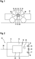
- FIG 1 shows a schematic representation of a vehicle 21 with a safety device 10.
- the safety device 10 comprises a housing 11. This housing 11 has a housing interior 13 in which a current-carrying element 12 is arranged.
- the current-carrying element 12 can be any electronic components/elements (eg power electronics 23 , DCDC converter 23 , etc.) which are enclosed by the housing 11 or are located in the housing 11 .
- the safety device 10 is connected to a battery 22 and an electric motor 20 and can be part of a charging device 25 (not shown here).
- FIG. 12 shows a schematic representation of a safety device 10. Identical elements with respect to FIG figure 1 are provided with the same reference numerals and are not explained in more detail.
- the safety device 10 includes a Housing 11, in the housing interior 13, a current-carrying element 12 (power electronics 23, a DCDC converter 23, etc.) is arranged.
- the housing 11 can have subdivisions or partitions within the housing 11 .
- a particle detector 15 is arranged in the housing interior 13 .
- the particle detector 15 is designed as a light barrier and consists of a radiation source 16 (transmitter) and a radiation receiver 17 (receiver).
- a light-emitting diode or a laser diode is advantageously used as the radiation source 16 .
- a photoresistor, a photodiode or a phototransistor are preferably used as the radiation receiver 17 .
- the radiation source 16 emits an electromagnetic beam which is directed towards the radiation receiver 17 . If particles 24 occur between the radiation receiver 17 and the radiation source 16, they are registered by the light barrier 15, which means that the safety device 10 switches off the voltage supply 26 of the current-carrying element 12.
- the safety device 10 monitors the radiation receiver 17 for radiation emitted by an arc 19 . If an arc 19 occurs, the resulting radiation is registered by the radiation receiver 17 in addition to the light emitted by the radiation source 16 .
- the radiation from the arc 19 has a typical high-frequency spectrum, which indicates the formation of an arc 19 .
- the safety device 10 can thus switch off the power supply 26 before the light barrier 15 has even detected particles 24 .
- the particle detector 15 is attached to or in an opening 18 of the housing 11 . If an arc 19 occurs, the air around the arc is abruptly heated, resulting in an increase in pressure at the point at which the arc 19 originates.
- the short-term pressure difference between the point of origin and the rest of the housing 11 means that the particles 24 are inevitably transported through existing housing openings such as the opening 18. Correspondingly, the particles are reliably detected by the particle detector 15 when they pass through the opening 18 .
- the pressure compensation opening present in the housing 11 is used as the opening 18 , for example.
Landscapes
- Engineering & Computer Science (AREA)
- Business, Economics & Management (AREA)
- General Physics & Mathematics (AREA)
- Physics & Mathematics (AREA)
- Emergency Management (AREA)
- Sustainable Energy (AREA)
- Transportation (AREA)
- Mechanical Engineering (AREA)
- Power Engineering (AREA)
- Sustainable Development (AREA)
- Life Sciences & Earth Sciences (AREA)
- Microelectronics & Electronic Packaging (AREA)
- Chemical & Material Sciences (AREA)
- Analytical Chemistry (AREA)
- Electric Propulsion And Braking For Vehicles (AREA)
- Gas-Insulated Switchgears (AREA)
- Investigating Or Analysing Materials By Optical Means (AREA)
- Geophysics And Detection Of Objects (AREA)
Description
- Die vorliegende Erfindung betrifft eine Sicherheitsvorrichtung gemäß dem Oberbegriff des Anspruchs 1, wie aus der
US 2014/0125487 A1 bekannt. - Lichtschranken zur Partikeldetektion sind aus der
WO 2014/194379 A1 bekannt. - Die
DE 20 2005 011 504 U1 beschreibt einen Lichtbogenmelder, der einen Hochfrequenzempfänger aufweist. - Elektrofahrzeuge und Hybridfahrzeuge verfügen üblicherweise über einen Elektromotor, der die gesamte oder einen Teil der Antriebsleistung liefert.
- In Hybridfahrzeugen wird ein Teil der, bei Elektrofahrzeugen die gesamte Antriebsleistung mit einem Elektromotor erzeugt. Die elektrische Energie muss mittels Leistungselektronik auf die für den elektrischen Antriebsmotor passende Spannung und Frequenz umgewandelt werden. Dafür werden leistungsstarke Gleichstromsteller und Wechselrichter verwendet, welche bei Hybridfahrzeugen die Energie bei Generatorbetrieb des Motors auch zur Zwischenspeicherung in Akkumulatoren oder Doppelschicht-Kondensatoren aufbereiten. Die unter Hochspannung stehenden Komponenten werden häufig auf geringstem Raum im jeweiligen Gehäuse angeordnet, um Platz einzusparen. Daraus folgt, dass aufgrund kleiner Abstände bzw. durch Metallsplitter oder andere mögliche leitfähige Verunreinigungen ein Lichtbogen bzw. Störlichtbogen entstehen kann.
- So müssen beispielsweise in Hochspannungs-DC Anwendungen, wie bspw. dem elektrischen Antriebsstrang eines Hybrid-Kfz zur Vermeidung von Kurzschlüssen und Lichtbögen im Gerät entsprechend den im Betrieb auftretenden Spannungen, dem zu berücksichtigenden Verschmutzungsgrad, der Homogenität der elektrischen Feldverteilung für Basis- und Funktionsisolierung Mindest-Abstände für Luft- und Kriechwege eingehalten werden. Eine Prämisse für die Festlegung dieser Mindest-Abstände ist, dass bei der Montage des Geräts und anhaftend an im Gerät eingebauten Komponenten keine leitfähigen Partikel entstehen oder eingetragen werden, die eine in den Sicherheitszuschlägen der Luft- und Kriechstrecken definierte Größe überschreiten. Die Lieferanten der Gerätekomponenten können die Maximalgröße eingetragener bzw. anhaftender Partikel (sog. "Flitter") nachteilig jedoch nur mit einer endlichen Wahrscheinlichkeit sicherstellen. Auch durch Feuchtigkeit und ungewollte Betauung kann ein Lichtbogen entstehen. Ein Störlichtbogen oder auch Fehlerlichtbogen ist in der elektrischen Energietechnik ein technisch unerwünscht auftretender Lichtbogen zwischen elektrischen Anlagenteilen. Bei ungenügendem Abstand oder ungenügender Isolation zwischen zwei elektrischen Potenzialen kann es zu einem ungewollten Spannungsüberschlag kommen, in dessen Verlauf ein Lichtbogen entsteht. Dieser Spannungsüberschlag kann auch in einem elektrischen Bauteil selber entstehen, weil sich die Kontakte zu langsam trennen, oder die Isolationsschicht zwischen den stromführenden Teilen ihrer Isolierfähigkeit beraubt wurde.
- Die Lichtbögen, die bei Spannungsüberschlag entstehen, setzen in der Regel die Lebensdauer des Bauteils massiv herab und können es im schlimmsten Fall auch zerstören. Lichtbögen sind bei Hochspannung führenden Bauteilen eine erhebliche Gefahr. Durch die große Lichtbogenleistung und hohe Temperatur des Lichtbogens kommt es neben der starken Lichtwirkung zu einem lauten Knall und brennbare Gegenstände in unmittelbarer Umgebung können Feuer fangen. Es besteht Brandgefahr. Im Niederspannungsbereich können Störlichtbögen infolge von Störstellen in elektrischen Leitungen auftreten, meist Leitungsschäden wie z.B. beschädigte Isolation infolge von Leitungsquetschungen oder zu geringe Biegungsradien bei elektrischen Leitungen. Hier können Kriechströme durch Verschmutzungen und Ablagerungen entstehen, die sich in einem Störlichtbogen entzünden. Auch bei losen Kontakten bei nicht korrekt montierten Bauteilen oder durch abgeknickte Leitungen können Störlichtbögen beispielsweise durch ionisierte Gase zwischen den losen Leitungsenden entstehen. Auf Leiterplatten, besonders häufig in Schaltnetzteilen, richten Überschläge erheblichen Schaden an, weil sich das Leitermaterial (Kupfer) auf dem Leiterplattenmaterial als Metalldampfschicht niederschlägt und Kriechstrecken überbrückt. Falls kein Austausch der gesamten Baugruppe möglich ist, werden derartige Schäden durch Schlitze in der Platine behoben; die neue Kriechstrecke besteht aus einem Luftspalt. Als Vorsorgemaßnahme dienen Lötaugen mit Hohlniet, dickere Kupferschichten, mit Draht verstärkte Leiterzüge, gekammerte Gehäuse sowie reichlich dimensionierte Kriechstrecken. Dem steht die Miniaturisierung aufgrund des geringen Bauraums wie z.B. in Hybrid- und Elektrofahrzeugen entgegen. Lichtbögen müssen somit unbedingt vermieden bzw. für den Fall, dass es zur Lichtbogenbildung kommt, rasch gelöscht werden.
- Bezüglich der Entstehung von Lichtbögen in Hochspannungs-DC Anwendungen, wie bspw. dem elektrischen Antriebsstrang eines Hybrid-Kfz müssen zur Lichtbogenerkennung die angeschlossenen Geräte wie Antriebsumrichter und DC/DC-Wandler mit geeigneten Sensoren überwacht werden. Als Reaktion auf einen erkannten Lichtbogen muss eine Abschaltung der Hochspannungsversorgung des vom Störlichtbogen / Lichtbogen betroffenen Geräts erfolgen bevor die im Lichtbogen umgesetzte Energie so hoch wird, dass der Lichtbogen auf das Gerätegehäuse überspringt oder aus dem Gerät austritt und damit einen Brandfall verursacht. Beim Auftreten eines Störlichtbogens entstehen in einem Gerät im Zeitbereich von Mikrosekunden nachteilig leitfähige Partikel (z.B. karbonisierte Isoliermaterialien, Ruß, Plasma, verdampfte metallische Leitmaterialien, etc.). Durch die thermische und elektromagnetische Wirkung des Störlichtbogens werden diese Partikel explosionsartig innerhalb des betroffenen Geräts verteilt. Diese Partikel werden als Ursache für das Zünden sekundärer Störlichtbögen innerhalb eines betroffenen Geräts betrachtet. Als Sensorik zur Erkennung eines Lichtbogens werden im Stand der Technik diverse Methoden vorgeschlagen. Zum einen findet eine Auswertung des Druckanstiegs durch thermische Wirkung eines Störlichtbogens innerhalb eines eingeschlossenen Gerätevolumens statt. Zum anderen wird die von einem Störlichtbogen im Gerät ausgesandten Strahlung (im sichtbaren und nicht sichtbaren Bereich) ausgewertet (siehe
DE 20 2005 011 504 U1 ). Weiterhin wird die akustische Wirkung beim Entstehen eines Störlichtbogens ausgewertet oder die in einem Gerät umgesetzte Energie (Quellen- / Senken-Vergleich) saldiert. - Alternativ wird das von einem Lichtbogen erzeugte Hochfrequenz-Spektrums ausgewertet. Einige der genannten Verfahren sind nachteilig aufgrund des hierfür erforderlichen Aufwands an Sensorik und erforderlicher Rechenleistung zur Erkennung, bzw. aufgrund der Störanfälligkeit in der Anwendung in Hochspannungs-DC-Anwendungen stark eingeschränkt. Einige der Verfahren haben insoweit Einschränkungen, dass in Geräten mit unterteiltem Gehäuse mehrere Erkennungseinrichtungen erforderlich werden um eine zur Begrenzung der Lichtbogenenergie erforderliche Detektionszeit einzuhalten. Plausibilisierung und Verknüpfung mehrerer Einzelsensoren bedingen zusätzlichen Rechenaufwand und Aufbau- und Verbindungstechnik (AVT).
- Es besteht daher der Bedarf nach einer Vorrichtung, durch die die Zündung sekundärer Lichtbögen im Gehäuse effektiv unterbunden wird.
- Die erfindungsgemäße Sicherheitsvorrichtung nach Anspruch 1 hat die Vorteile, dass die Entstehung sekundärer Lichtbögen unterbunden wird und die Entstehung von Lichtbögen generell detektiert werden kann.
- Erfindungsgemäß ist dazu eine Sicherheitsvorrichtung vorgesehen, wobei die Sicherheitsvorrichtung ein Gehäuse mit mindestens einem stromführenden Element umfasst, wobei das stromführende Element im Gehäuseinnenraum angeordnet ist und von dem Gehäuse umschlossen wird. Im Gehäuseinnenraum des Gehäuses ist ein Partikeldetektor angeordnet, der den Gehäuseinnenraum bezüglich der Entstehung von Partikeln überwacht. Vorteilhafterweise erkennt der Partikeldetektor die bei einem Lichtbogen entstehenden Partikel, sobald diese vom Entstehungsort (dem primären Lichtbogen) im Gesamtgerät ausgestreut werden. Werden Partikel im Gehäuse durch den Partikeldetektor erkannt, kann vorteilhafterweise eine Abschaltung der Hochspannungsversorgung des Gerätes erfolgen, wodurch einem evtl. entstehenden Brandfall vorgebeugt werden kann.
- Durch die in den abhängigen Ansprüchen genannten Maßnahmen sind vorteilhafte Weiterbildungen des in dem unabhängigen Anspruch angegebenen Verfahrens möglich.
- Erfindungsgemäß ist der Partikeldetektor eine Lichtschranke. Eine Lichtschranke ist in der Optoelektronik ein System, das die Unterbrechung eines Lichtstrahls erkennt und als elektrisches Signal anzeigt. Vorteilhafterweise können mittels der Lichtschranke bewegliche Objekte wie z.B. Partikel berührungslos detektiert werden.
- Weiterhin ist erfindungsgemäß vorgesehen, dass der Partikeldetektor eine Strahlungsquelle (Sender) und einen Strahlungsempfänger (Empfänger) aufweist. Ein funktionaler Test der Lichtschranke (mit einem zwischen Strahlungsquelle und einem Strahlungsempfänger liegenden Detektionspfad), ist vorteilhafterweise jederzeit einfach über die beiden Lichtschranken-Komponenten Sender und Empfänger möglich.
- Als Strahlungsquelle wird vorteilhaft eine Leuchtdiode oder eine Laserdiode verwendet. Als Leuchtdioden eignen sich beispielsweise solche mit einer Wellenlänge von 660 nm (sichtbares rotes Licht) oder Infrarot-LEDs mit 880-940 nm im Infrarotbereich. Infrarotlicht hat den Vorteil, auf dunklen Materialien eine höhere Reichweite zu erzielen, auch ist es für das menschliche Auge nicht sichtbar. Der Vorteil beim Rotlicht besteht in der einfacheren Einstellung des Sensorsystems durch den sichtbaren Lichtfleck. Für besonders präzise Anwendungen (Kleinteileerkennung, hohe Wiederholgenauigkeit) wird i. d. R. Licht aus einer Laserdiode eingesetzt.
- Als Strahlungsempfänger werden vorzugsweise ein Fotowiderstand, eine Fotodiode oder ein Fototransistor eingesetzt.
- Je mehr Licht auf den Fotowiderstand fällt, desto kleiner wird sein elektrischer Widerstand, wodurch die Detektion von Partikeln möglich ist. Im Vergleich zu anderen Lichtsensoren reagieren Fotowiderstände allerdings eher langsam.
- Fotodioden hingegen werden unter anderem verwendet, um Licht in eine elektrische Spannung oder einen elektrischen Strom umzusetzen oder um mit Licht übertragene Informationen zu empfangen. Treten Partikel in den Lichtweg der Lichtschranke, trifft entsprechend weniger Licht auf den Empfänger, wodurch eine geringer elektrische Spannung registriert und somit auf das Vorhandensein von Partikeln im Gehäuse geschlossen werden kann.
- Fototransistoren sind vorteilhafterweise wesentlich empfindlicher als Fotodioden, da sie gleichzeitig als Verstärker wirken.
- Die Sicherheitsvorrichtung überwacht erfindungsgemäß den Strahlungsempfänger auf eine von einem Lichtbogen ausgesandte Strahlung. Ein Lichtbogen weist bei seiner Entstehung ein Hochfrequenz-Spektrum auf, das mittels des Strahlungsempfängers empfangen und anschließend ausgewertet werden kann. Es ist somit mittels der Lichtschranke nicht nur möglich, Partikel zu detektieren und somit die Entstehung von Sekundärlichtbögen zu vermeiden, sondern auch die Entstehung von Lichtbögen generell zu detektieren.
- Zusätzlich ist vorteilhaft, die Lichtschranke an oder in einer Öffnung des Gehäuses anzuordnen. Alternativ ist die Lichtschranke zwischen Unterteilungen oder Abschottungen innerhalb des Gerätes eingebaut. Der mit der Entstehung eines Lichtbogens verbundene Druckanstieg am Entstehungsort führt zu einer kurzzeitigen Druckdifferenz zwischen Entstehungsort und restlichem Gehäuse, wodurch Partikel zwangsläufig durch vorhandene Öffnungen bzw. Gehäuseöffnung transportiert werden und daher an dieser Stelle - an der die Lichtschranke vorteilhafterweise angeordnet ist - sicher erkannt werden können.
- Da ein Austritt der vom Störlichtbogen generierten Partikel aus dem Gerätegehäuse eher unerwünscht ist, verbietet es sich, zur Partikeldetektion zusätzliche Geräteöffnungen an der Außenseite des Geräts vorzusehen. Entsprechend werden als Öffnungen die in Geräten üblicherweise vorhandene Druckausgleichsöffnung (DAE) für das erfindungsgemäße Verfahren genutzt.
- Weitere Merkmale und Vorteile der vorliegenden Erfindung werden dem Fachmann aus der nachfolgenden Beschreibung beispielhafter Ausführungsformen, die jedoch nicht als die Erfindung beschränkend auszulegen sind, unter Bezugnahme auf die beigelegten Zeichnungen ersichtlich.
- Es zeigen:
- Fig. 1:
- eine schematische Darstellung eines Fahrzeuges und der Sicherheitsvorrichtung;
- Fig. 2:
- eine schematische Darstellung einer Sicherheitsvorrichtung;
- Alle Figuren sind lediglich schematische Darstellungen des erfindungsgemäßen Verfahrens bzw. seiner Bestandteile gemäß Ausführungsbeispielen der Erfindung. Insbesondere Abstände und Größenrelationen sind in den Figuren nicht maßstabsgetreu wiedergegeben. In den verschiedenen Figuren sind sich entsprechende Elemente mit den gleichen Referenznummern versehen.
-
Figur 1 zeigt eine schematische Darstellung eines Fahrzeugs 21 mit einer Sicherheitsvorrichtung 10. Die Sicherheitsvorrichtung 10 umfasst ein Gehäuse 11. Dieses Gehäuse 11 besitzt einen Gehäuseinnenraum 13, in dem ein stromführendes Element 12 angeordnet ist. Bei dem stromführenden Element 12 kann es sich um beliebige Elektronikbauteile / -elemente handeln (z.B. Leistungselektronik 23, DCDC-Wandler 23, etc.), die von dem Gehäuse 11 umschlossen werden bzw. sich im Gehäuse 11 befinden. Die Sicherheitsvorrichtung 10 ist mit einer Batterie 22 und einem Elektromotor 20 verbunden und kann Teil einer Ladevorrichtung 25 (hier nicht dargestellt) sein. -
Figur 2 zeigt eine schematische Darstellung einer Sicherheitsvorrichtung 10. Gleiche Elemente in Bezug aufFigur 1 sind mit gleichen Bezugszeichen versehen und werden nicht näher erläutert. Die Sicherheitsvorrichtung 10 umfasst ein Gehäuse 11, in dessen Gehäuseinnenraum 13 ein stromführendes Element 12 (eine Leistungselektronik 23, ein DCDC Wandler 23, etc.) angeordnet ist. Das Gehäuse 11 kann Unterteilungen bzw. Abschottungen innerhalb des Gehäuses 11 aufweisen. In dem Gehäuseinnenraum 13 ist ein Partikeldetektor 15 angeordnet. - Der Partikeldetektor 15 ist als Lichtschranke ausgeführt und besteht aus einer Strahlungsquelle 16 (Sender) und einem Strahlungsempfänger 17 (Empfänger).
- Als Strahlungsquelle 16 wird vorteilhaft eine Leuchtdiode oder eine Laserdiode verwendet. Als Strahlungsempfänger 17 werden vorzugsweise ein Fotowiderstand, eine Fotodiode oder ein Fototransistor eingesetzt. Die Strahlungsquelle 16 sendet einen elektromagnetischen Strahl aus, der auf den Strahlungsempfänger 17 gerichtet ist. Treten Partikel 24 zwischen den Strahlungsempfänger 17 und die Strahlungsquelle 16 werden diese durch die Lichtschranke 15 registriert, was dazu führt, dass die Sicherheitsvorrichtung 10 die Spannungsversorgung 26 des stromführenden Elementes 12 abschaltet.
- Weiterhin überwacht die Sicherheitsvorrichtung 10 den Strahlungsempfänger 17 auf eine von einem Lichtbogen 19 ausgesandte Strahlung. Entsteht ein Lichtbogen 19, wird die dabei entstehende Strahlung von dem Strahlungsempfänger 17 zusätzlich zu der von der Strahlungsquelle 16 ausgesandten Licht registriert. Die Strahlung des Lichtbogens 19 weist ein typisches Hochfrequenz-Spektrum auf, das auf die Entstehung eines Lichtbogens 19 hindeutet. Somit kann die Sicherheitsvorrichtung 10 bereits die Spannungsversorgung 26 abschalten, bevor mittels der Lichtschrank 15 überhaupt Partikel 24 detektiert worden sind. Der Partikeldetektor 15 ist an oder in einer Öffnung 18 des Gehäuses 11 angebracht. Entsteht ein Lichtbogen 19, wird die Luft um den Lichtbogen herum schlagartig erwärmt, wodurch es zu einem Druckanstieg am Entstehungsort des Lichtbogens 19 kommt. Die kurzzeitige Druckdifferenz zwischen Entstehungsort und dem restlichen Gehäuse 11 führt dazu, dass die Partikel 24 zwangsläufig durch vorhandene Gehäuseöffnungen wie z.B. die Öffnung 18 transportiert werden. Entsprechend werden die Partikel beim Durchtritt durch die Öffnung 18 durch den Partikeldetektor 15 sicher erkannt. Als Öffnung 18 wird beispielsweise die im Gehäuse 11 vorhandene Druckausgleichsöffnung genutzt.
Claims (5)
- Sicherheitsvorrichtung (10), umfassend ein Gehäuse (11) mit mindestens einem stromführenden Element (12), das mit einer Spannungsversorgung (26) verbunden ist, wobei das stromführende Element (12) im Gehäuseinnenraum (13) angeordnet ist und von dem Gehäuse (11) umschlossen wird, wobei im Gehäuseinnenraum (13) des Gehäuses (11) ein Partikeldetektor (15) angeordnet ist, der ausgestaltet ist, den Gehäuseinnenraum (13) bezüglich der Entstehung von Partikeln (24) zu überwachen,wobei der Partikeldetektor (15) eine Lichtschranke ist,wobei die Lichtschranke eine Strahlungsquelle (16) und einen Strahlungsempfänger (17) aufweist,wobei der Strahlungsempfänger (17) dazu eingerichtet ist, die von einem Lichtbogen ausgesandte Strahlung zu empfangen und auszuwerten und zu detektieren, wenn Partikel in den Lichtweg der Lichtschranke treten,die Sicherheitsvorrichtung (10) ausgestaltet ist, beim Registrieren von Partikeln (24) durch die Lichtschranke die Spannungsversorgung (26) abzuschalten, die Sicherheitsvorrichtung (10) ausgestaltet ist, den Strahlungsempfänger (17) auf eine von einem Lichtbogen (19) ausgesandte Strahlung zu überwachen, indem die von dem Lichtbogen (19) ausgesandte Strahlung von dem Strahlungsempfänger (17) zusätzlich zur von der Strahlungsquelle ausgesandten Strahlung registrierbar ist,die Sicherheitsvorrichtung (10) ausgestaltet ist, beim Registrieren der von dem Lichtbogen (19) ausgesandten Strahlung die Spannungsversorgung (26) abzuschalten, bevor die Partikel (24) von der Lichtschranke detektiert worden sind.
- Sicherheitsvorrichtung (10) nach Anspruch 1, dadurch gekennzeichnet, dass als Strahlungsquelle (16) eine Leuchtdiode oder eine Laserdiode verwendet wird.
- Sicherheitsvorrichtung (10) nach einem der vorhergehenden Ansprüche, dadurch gekennzeichnet, dass als Strahlungsempfänger (17) vorzugsweise eine Fotodiode, ein Fototransistor oder ein Fotowiderstand eingesetzt ist.
- Sicherheitsvorrichtung (10) nach einem der vorhergehenden Ansprüche, dadurch gekennzeichnet, dass die Lichtschranke (15) an oder in einer Öffnung (18) des Gehäuses (11) angeordnet ist.
- Sicherheitsvorrichtung (10) nach Anspruch 4, dadurch gekennzeichnet, dass die Öffnung (18) eine Druckausgleichsöffnung des Gehäuses (11) ist.
Applications Claiming Priority (2)
| Application Number | Priority Date | Filing Date | Title |
|---|---|---|---|
| DE102016217431.2A DE102016217431A1 (de) | 2016-09-13 | 2016-09-13 | Verfahren zum Betrieb einer Sicherheitsvorrichtung |
| PCT/EP2017/069984 WO2018050360A1 (de) | 2016-09-13 | 2017-08-08 | Verfahren zum betrieb einer sicherheitsvorrichtung |
Publications (2)
| Publication Number | Publication Date |
|---|---|
| EP3513392A1 EP3513392A1 (de) | 2019-07-24 |
| EP3513392B1 true EP3513392B1 (de) | 2023-03-01 |
Family
ID=59713976
Family Applications (1)
| Application Number | Title | Priority Date | Filing Date |
|---|---|---|---|
| EP17758067.7A Active EP3513392B1 (de) | 2016-09-13 | 2017-08-08 | Sicherheitsvorrichtung |
Country Status (7)
| Country | Link |
|---|---|
| US (1) | US10793005B2 (de) |
| EP (1) | EP3513392B1 (de) |
| JP (1) | JP2019537702A (de) |
| KR (1) | KR20190053887A (de) |
| CN (1) | CN109661689B (de) |
| DE (1) | DE102016217431A1 (de) |
| WO (1) | WO2018050360A1 (de) |
Families Citing this family (2)
| Publication number | Priority date | Publication date | Assignee | Title |
|---|---|---|---|---|
| EP3941168A1 (de) * | 2020-07-14 | 2022-01-19 | ZKW Group GmbH | Fahrzeugmodul mit einer manipulationserkennenden elektronischen steuereinheit |
| DE102021211101A1 (de) | 2021-10-01 | 2023-04-06 | Vitesco Technologies Germany Gmbh | (Leistungs-)Elektronikvorrichtung |
Family Cites Families (34)
| Publication number | Priority date | Publication date | Assignee | Title |
|---|---|---|---|---|
| US4132814A (en) * | 1977-11-07 | 1979-01-02 | Porta Systems Corp. | Anti-dusting process for carbon resistors |
| JP2766680B2 (ja) * | 1989-08-04 | 1998-06-18 | 大阪電気株式会社 | プラズマワイヤ溶射加工方法およびその装置 |
| JP3175434B2 (ja) | 1993-10-21 | 2001-06-11 | 株式会社日立製作所 | ガス絶縁開閉装置 |
| US5548461A (en) * | 1994-07-11 | 1996-08-20 | Mcdonnell Douglas Corporation | Arc suppressor |
| JPH0843305A (ja) * | 1994-07-29 | 1996-02-16 | Nippon Kagaku Kogyo Kk | 煙濃度測定装置 |
| US5633501A (en) * | 1995-06-07 | 1997-05-27 | Pittway Corporation | Combination photoelectric and ionization smoke detector |
| JP2001307834A (ja) * | 2000-04-17 | 2001-11-02 | Fujikura Ltd | コネクタ及び配線構造 |
| JP2003315268A (ja) * | 2002-04-19 | 2003-11-06 | Mitsubishi Electric Corp | 粉塵検出装置 |
| JP4006733B2 (ja) * | 2002-12-16 | 2007-11-14 | 学校法人東海大学 | 燃焼排気中のすす凝集体の質量濃度測定方法及び装置 |
| DE10345183B4 (de) * | 2003-09-29 | 2005-10-13 | Siemens Ag | Vorrichtung zum Erfassen von Kontaktabbrand in Schaltgeräten |
| US7225676B2 (en) * | 2004-05-18 | 2007-06-05 | Jennings Technology | Method and apparatus for the detection of high pressure conditions in a vacuum switching device |
| DE202005011504U1 (de) | 2005-07-21 | 2006-11-30 | Liebherr-Transportation Systems Ges. M.B.H. | Lichtbogenmelder |
| GB0709824D0 (en) * | 2007-05-23 | 2007-07-04 | Kitchener Renato | Intrinsically safe power and communication |
| CN101615040B (zh) * | 2009-07-22 | 2012-05-09 | 苏州新亚科技有限公司 | 具有接触器故障检测与控制的温度控制系统 |
| ES2384146A1 (es) * | 2010-02-02 | 2012-07-02 | General Electric Company | Circuito de detección, sistema de detección y método para la construcción de sistemas de detección. |
| CN103189734B (zh) * | 2010-11-01 | 2015-09-23 | 英派尔科技开发有限公司 | 纳米粒子检测器 |
| JP5788738B2 (ja) * | 2011-08-26 | 2015-10-07 | 富士フイルム株式会社 | 放射線検出器の製造方法 |
| JP2013105660A (ja) * | 2011-11-15 | 2013-05-30 | Showa Denshi Kogyo Kk | アーク放電監視装置 |
| CN202333765U (zh) * | 2011-11-25 | 2012-07-11 | 中国有色(沈阳)冶金机械有限公司 | 一种安全的电机驱动回路 |
| JP3175434U (ja) * | 2012-02-23 | 2012-05-10 | 西日本旅客鉄道株式会社 | 直流高速度遮断器のアーク放電監視装置 |
| US9007222B2 (en) * | 2012-09-21 | 2015-04-14 | Google Inc. | Detector unit and sensing chamber therefor |
| CN103018145A (zh) * | 2012-10-12 | 2013-04-03 | 桂林电子科技大学 | 一种新型的pm2.5质量浓度实时监测装置与监测方法 |
| US20140104067A1 (en) * | 2012-10-16 | 2014-04-17 | Jung-Tang Huang | Smoke Sensor |
| US8742939B2 (en) * | 2012-11-08 | 2014-06-03 | Advanced Energy Industries, Inc. | Aspirating particle sensor for smoke detection within an electronics enclosure |
| WO2014194379A1 (en) * | 2013-06-03 | 2014-12-11 | Xtralis Technologies Ltd | Particle detection system and related methods |
| WO2015009350A1 (en) * | 2013-07-16 | 2015-01-22 | Leeo, Inc. | Electronic device with environmental monitoring |
| CN204068222U (zh) * | 2014-08-11 | 2014-12-31 | 国家电网公司 | 一种开关柜电弧光防护装置 |
| CN106796856B (zh) * | 2014-10-03 | 2020-03-06 | 管理科学有限公司 | 防止电气导管中电弧故障的方法、系统和装置 |
| CN204441216U (zh) * | 2015-02-13 | 2015-07-01 | 天津市赛晨电气设备有限公司 | 一种过载报警断路器 |
| CN204696543U (zh) * | 2015-06-26 | 2015-10-07 | 宁夏天地经纬电力设备工程有限公司 | 一种抽屉式低压开关柜 |
| CN105136689B (zh) * | 2015-08-27 | 2018-04-10 | 中国航天空气动力技术研究院 | 电弧加热器电极烧蚀的实时监测方法 |
| CN205565367U (zh) * | 2016-05-05 | 2016-09-07 | 新疆新华能西源电器有限公司 | 负荷开关熔断器组合电气柜 |
| US10755544B2 (en) * | 2017-03-16 | 2020-08-25 | CoEvac, LLC | Automatic smoke/carbon monoxide evacuation power switch method and system |
| AU2018278833B2 (en) * | 2017-05-31 | 2023-09-21 | Eric V. Gonzales | Smoke device and smoke detection circuit |
-
2016
- 2016-09-13 DE DE102016217431.2A patent/DE102016217431A1/de not_active Withdrawn
-
2017
- 2017-08-08 US US16/331,565 patent/US10793005B2/en active Active
- 2017-08-08 CN CN201780056004.3A patent/CN109661689B/zh active Active
- 2017-08-08 KR KR1020197010384A patent/KR20190053887A/ko not_active Withdrawn
- 2017-08-08 WO PCT/EP2017/069984 patent/WO2018050360A1/de not_active Ceased
- 2017-08-08 JP JP2019513940A patent/JP2019537702A/ja active Pending
- 2017-08-08 EP EP17758067.7A patent/EP3513392B1/de active Active
Also Published As
| Publication number | Publication date |
|---|---|
| CN109661689B (zh) | 2021-07-27 |
| DE102016217431A1 (de) | 2018-03-15 |
| KR20190053887A (ko) | 2019-05-20 |
| US20190210466A1 (en) | 2019-07-11 |
| EP3513392A1 (de) | 2019-07-24 |
| US10793005B2 (en) | 2020-10-06 |
| CN109661689A (zh) | 2019-04-19 |
| WO2018050360A1 (de) | 2018-03-22 |
| JP2019537702A (ja) | 2019-12-26 |
Similar Documents
| Publication | Publication Date | Title |
|---|---|---|
| US9070797B2 (en) | Photovoltaic installation | |
| DE69327795T2 (de) | Elektronenlinearbeschleuniger zur verarbeitung von industriellem material | |
| WO1995025374A1 (de) | Verfahren zum schutz einer elektrischen anlage, insbesondere einer gleichspannungs-, z.b. einer photovoltaik-anlage, anlage sowie detektionseinheit für die anlage | |
| EP3861359B1 (de) | Verfahren zum bestimmen eines kurzschlusses mit auftreten eines lichtbogens an einem elektrischen leiter | |
| DE60130482T2 (de) | Verfahren und einrichtung zur überwachung des vakuumgrades in einem vakuum-unterbrecherschalter | |
| EP3513392B1 (de) | Sicherheitsvorrichtung | |
| DE102014102509A1 (de) | Verfahren zur temperaturermittlung | |
| EP3830922B1 (de) | Lichtbogenerkennung | |
| DE102014108870A1 (de) | Verfahren und Vorrichtung zur Lichtbogenerkennung | |
| DE102015122073B3 (de) | System zur Diagnose des technischen Betriebszustandes einer elektrischen Hochspannungs- und Mittelspannungsanlage | |
| EP2838172B1 (de) | Vorrichtung und verfahren zur detektion von störlichtbögen | |
| WO2014090378A1 (de) | Transformatorschutzsystem | |
| DE4316239A1 (de) | Verfahren zur Lichtbogenerkennung | |
| DE102016216321A1 (de) | Schaltvorrichtung und Verfahren zum Schalten eines Stromes | |
| WO2013013713A1 (de) | Ladekabel | |
| DE102010063421A1 (de) | Schaltungsanordnung und Verfahren zum Detektieren eines Lichtbogens | |
| DE9212672U1 (de) | Einrichtung zur Erkennung von Störlichtbögen, insbesondere an Sammelschienenanordnungen in Niederspannungs-Schaltanlagen | |
| DE102016103782B4 (de) | Anordnung mit einem einen Mikroprozessor umfassenden Sensor und einer Tasterschnittstelle | |
| DE102013011128A1 (de) | Vorrichtung und Verfahren zum Überwachen eines Gleichspannungskreises eines Kraftwagens | |
| DE102017212206A1 (de) | Verfahren zum Betrieb einer Sicherheitsvorrichtung | |
| DE102022116657A1 (de) | Steckverbinder mit einer einrichtung zur erkennung eines isolationsfehlers, verfahren zur erkennung eines isolationsfehlers bei einem steckverbinder und anordnung mit einem solchen steckverbinder | |
| DE102023103932A1 (de) | Vorrichtung für ein induktives Ladesystem sowie induktives Ladesystem | |
| DE102021124641A1 (de) | Elektrischer Energiespeicher mit Antennen zur Defektdetektion sowie Kraftfahrzeug | |
| DE19801207A1 (de) | Elektrische Anlage mit abgesicherter Generatorleitung | |
| DE102016213222A1 (de) | Sicherheitsvorrichtung |
Legal Events
| Date | Code | Title | Description |
|---|---|---|---|
| STAA | Information on the status of an ep patent application or granted ep patent |
Free format text: STATUS: UNKNOWN |
|
| STAA | Information on the status of an ep patent application or granted ep patent |
Free format text: STATUS: THE INTERNATIONAL PUBLICATION HAS BEEN MADE |
|
| PUAI | Public reference made under article 153(3) epc to a published international application that has entered the european phase |
Free format text: ORIGINAL CODE: 0009012 |
|
| STAA | Information on the status of an ep patent application or granted ep patent |
Free format text: STATUS: REQUEST FOR EXAMINATION WAS MADE |
|
| 17P | Request for examination filed |
Effective date: 20190415 |
|
| AK | Designated contracting states |
Kind code of ref document: A1 Designated state(s): AL AT BE BG CH CY CZ DE DK EE ES FI FR GB GR HR HU IE IS IT LI LT LU LV MC MK MT NL NO PL PT RO RS SE SI SK SM TR |
|
| AX | Request for extension of the european patent |
Extension state: BA ME |
|
| DAV | Request for validation of the european patent (deleted) | ||
| DAX | Request for extension of the european patent (deleted) | ||
| RAP1 | Party data changed (applicant data changed or rights of an application transferred) |
Owner name: ROBERT BOSCH GMBH |
|
| STAA | Information on the status of an ep patent application or granted ep patent |
Free format text: STATUS: EXAMINATION IS IN PROGRESS |
|
| 17Q | First examination report despatched |
Effective date: 20210624 |
|
| GRAP | Despatch of communication of intention to grant a patent |
Free format text: ORIGINAL CODE: EPIDOSNIGR1 |
|
| STAA | Information on the status of an ep patent application or granted ep patent |
Free format text: STATUS: GRANT OF PATENT IS INTENDED |
|
| RIC1 | Information provided on ipc code assigned before grant |
Ipc: H05K 7/14 20060101ALN20221007BHEP Ipc: G08B 17/12 20060101ALI20221007BHEP Ipc: G08B 17/117 20060101ALI20221007BHEP Ipc: B60L 3/04 20060101ALI20221007BHEP Ipc: H02H 1/00 20060101ALI20221007BHEP Ipc: G08B 17/10 20060101AFI20221007BHEP |
|
| RIC1 | Information provided on ipc code assigned before grant |
Ipc: H05K 7/14 20060101ALN20221020BHEP Ipc: G08B 17/12 20060101ALI20221020BHEP Ipc: G08B 17/117 20060101ALI20221020BHEP Ipc: B60L 3/04 20060101ALI20221020BHEP Ipc: H02H 1/00 20060101ALI20221020BHEP Ipc: G08B 17/10 20060101AFI20221020BHEP |
|
| INTG | Intention to grant announced |
Effective date: 20221116 |
|
| GRAS | Grant fee paid |
Free format text: ORIGINAL CODE: EPIDOSNIGR3 |
|
| GRAA | (expected) grant |
Free format text: ORIGINAL CODE: 0009210 |
|
| STAA | Information on the status of an ep patent application or granted ep patent |
Free format text: STATUS: THE PATENT HAS BEEN GRANTED |
|
| AK | Designated contracting states |
Kind code of ref document: B1 Designated state(s): AL AT BE BG CH CY CZ DE DK EE ES FI FR GB GR HR HU IE IS IT LI LT LU LV MC MK MT NL NO PL PT RO RS SE SI SK SM TR |
|
| REG | Reference to a national code |
Ref country code: GB Ref legal event code: FG4D Free format text: NOT ENGLISH |
|
| REG | Reference to a national code |
Ref country code: CH Ref legal event code: EP Ref country code: AT Ref legal event code: REF Ref document number: 1551540 Country of ref document: AT Kind code of ref document: T Effective date: 20230315 |
|
| REG | Reference to a national code |
Ref country code: DE Ref legal event code: R096 Ref document number: 502017014466 Country of ref document: DE |
|
| REG | Reference to a national code |
Ref country code: IE Ref legal event code: FG4D Free format text: LANGUAGE OF EP DOCUMENT: GERMAN |
|
| REG | Reference to a national code |
Ref country code: LT Ref legal event code: MG9D |
|
| REG | Reference to a national code |
Ref country code: NL Ref legal event code: MP Effective date: 20230301 |
|
| PG25 | Lapsed in a contracting state [announced via postgrant information from national office to epo] |
Ref country code: RS Free format text: LAPSE BECAUSE OF FAILURE TO SUBMIT A TRANSLATION OF THE DESCRIPTION OR TO PAY THE FEE WITHIN THE PRESCRIBED TIME-LIMIT Effective date: 20230301 Ref country code: NO Free format text: LAPSE BECAUSE OF FAILURE TO SUBMIT A TRANSLATION OF THE DESCRIPTION OR TO PAY THE FEE WITHIN THE PRESCRIBED TIME-LIMIT Effective date: 20230601 Ref country code: LV Free format text: LAPSE BECAUSE OF FAILURE TO SUBMIT A TRANSLATION OF THE DESCRIPTION OR TO PAY THE FEE WITHIN THE PRESCRIBED TIME-LIMIT Effective date: 20230301 Ref country code: LT Free format text: LAPSE BECAUSE OF FAILURE TO SUBMIT A TRANSLATION OF THE DESCRIPTION OR TO PAY THE FEE WITHIN THE PRESCRIBED TIME-LIMIT Effective date: 20230301 Ref country code: HR Free format text: LAPSE BECAUSE OF FAILURE TO SUBMIT A TRANSLATION OF THE DESCRIPTION OR TO PAY THE FEE WITHIN THE PRESCRIBED TIME-LIMIT Effective date: 20230301 Ref country code: ES Free format text: LAPSE BECAUSE OF FAILURE TO SUBMIT A TRANSLATION OF THE DESCRIPTION OR TO PAY THE FEE WITHIN THE PRESCRIBED TIME-LIMIT Effective date: 20230301 |
|
| PG25 | Lapsed in a contracting state [announced via postgrant information from national office to epo] |
Ref country code: SE Free format text: LAPSE BECAUSE OF FAILURE TO SUBMIT A TRANSLATION OF THE DESCRIPTION OR TO PAY THE FEE WITHIN THE PRESCRIBED TIME-LIMIT Effective date: 20230301 Ref country code: PL Free format text: LAPSE BECAUSE OF FAILURE TO SUBMIT A TRANSLATION OF THE DESCRIPTION OR TO PAY THE FEE WITHIN THE PRESCRIBED TIME-LIMIT Effective date: 20230301 Ref country code: NL Free format text: LAPSE BECAUSE OF FAILURE TO SUBMIT A TRANSLATION OF THE DESCRIPTION OR TO PAY THE FEE WITHIN THE PRESCRIBED TIME-LIMIT Effective date: 20230301 Ref country code: GR Free format text: LAPSE BECAUSE OF FAILURE TO SUBMIT A TRANSLATION OF THE DESCRIPTION OR TO PAY THE FEE WITHIN THE PRESCRIBED TIME-LIMIT Effective date: 20230602 Ref country code: FI Free format text: LAPSE BECAUSE OF FAILURE TO SUBMIT A TRANSLATION OF THE DESCRIPTION OR TO PAY THE FEE WITHIN THE PRESCRIBED TIME-LIMIT Effective date: 20230301 |
|
| PG25 | Lapsed in a contracting state [announced via postgrant information from national office to epo] |
Ref country code: SM Free format text: LAPSE BECAUSE OF FAILURE TO SUBMIT A TRANSLATION OF THE DESCRIPTION OR TO PAY THE FEE WITHIN THE PRESCRIBED TIME-LIMIT Effective date: 20230301 Ref country code: RO Free format text: LAPSE BECAUSE OF FAILURE TO SUBMIT A TRANSLATION OF THE DESCRIPTION OR TO PAY THE FEE WITHIN THE PRESCRIBED TIME-LIMIT Effective date: 20230301 Ref country code: PT Free format text: LAPSE BECAUSE OF FAILURE TO SUBMIT A TRANSLATION OF THE DESCRIPTION OR TO PAY THE FEE WITHIN THE PRESCRIBED TIME-LIMIT Effective date: 20230703 Ref country code: EE Free format text: LAPSE BECAUSE OF FAILURE TO SUBMIT A TRANSLATION OF THE DESCRIPTION OR TO PAY THE FEE WITHIN THE PRESCRIBED TIME-LIMIT Effective date: 20230301 Ref country code: CZ Free format text: LAPSE BECAUSE OF FAILURE TO SUBMIT A TRANSLATION OF THE DESCRIPTION OR TO PAY THE FEE WITHIN THE PRESCRIBED TIME-LIMIT Effective date: 20230301 |
|
| PG25 | Lapsed in a contracting state [announced via postgrant information from national office to epo] |
Ref country code: SK Free format text: LAPSE BECAUSE OF FAILURE TO SUBMIT A TRANSLATION OF THE DESCRIPTION OR TO PAY THE FEE WITHIN THE PRESCRIBED TIME-LIMIT Effective date: 20230301 Ref country code: IS Free format text: LAPSE BECAUSE OF FAILURE TO SUBMIT A TRANSLATION OF THE DESCRIPTION OR TO PAY THE FEE WITHIN THE PRESCRIBED TIME-LIMIT Effective date: 20230701 |
|
| REG | Reference to a national code |
Ref country code: DE Ref legal event code: R097 Ref document number: 502017014466 Country of ref document: DE |
|
| PLBE | No opposition filed within time limit |
Free format text: ORIGINAL CODE: 0009261 |
|
| STAA | Information on the status of an ep patent application or granted ep patent |
Free format text: STATUS: NO OPPOSITION FILED WITHIN TIME LIMIT |
|
| PG25 | Lapsed in a contracting state [announced via postgrant information from national office to epo] |
Ref country code: SI Free format text: LAPSE BECAUSE OF FAILURE TO SUBMIT A TRANSLATION OF THE DESCRIPTION OR TO PAY THE FEE WITHIN THE PRESCRIBED TIME-LIMIT Effective date: 20230301 Ref country code: DK Free format text: LAPSE BECAUSE OF FAILURE TO SUBMIT A TRANSLATION OF THE DESCRIPTION OR TO PAY THE FEE WITHIN THE PRESCRIBED TIME-LIMIT Effective date: 20230301 |
|
| 26N | No opposition filed |
Effective date: 20231204 |
|
| PG25 | Lapsed in a contracting state [announced via postgrant information from national office to epo] |
Ref country code: MC Free format text: LAPSE BECAUSE OF FAILURE TO SUBMIT A TRANSLATION OF THE DESCRIPTION OR TO PAY THE FEE WITHIN THE PRESCRIBED TIME-LIMIT Effective date: 20230301 |
|
| REG | Reference to a national code |
Ref country code: CH Ref legal event code: PL |
|
| PG25 | Lapsed in a contracting state [announced via postgrant information from national office to epo] |
Ref country code: MC Free format text: LAPSE BECAUSE OF FAILURE TO SUBMIT A TRANSLATION OF THE DESCRIPTION OR TO PAY THE FEE WITHIN THE PRESCRIBED TIME-LIMIT Effective date: 20230301 |
|
| PG25 | Lapsed in a contracting state [announced via postgrant information from national office to epo] |
Ref country code: LU Free format text: LAPSE BECAUSE OF NON-PAYMENT OF DUE FEES Effective date: 20230808 |
|
| GBPC | Gb: european patent ceased through non-payment of renewal fee |
Effective date: 20230808 |
|
| PG25 | Lapsed in a contracting state [announced via postgrant information from national office to epo] |
Ref country code: LU Free format text: LAPSE BECAUSE OF NON-PAYMENT OF DUE FEES Effective date: 20230808 Ref country code: CH Free format text: LAPSE BECAUSE OF NON-PAYMENT OF DUE FEES Effective date: 20230831 |
|
| REG | Reference to a national code |
Ref country code: BE Ref legal event code: MM Effective date: 20230831 |
|
| REG | Reference to a national code |
Ref country code: IE Ref legal event code: MM4A |
|
| PG25 | Lapsed in a contracting state [announced via postgrant information from national office to epo] |
Ref country code: IT Free format text: LAPSE BECAUSE OF FAILURE TO SUBMIT A TRANSLATION OF THE DESCRIPTION OR TO PAY THE FEE WITHIN THE PRESCRIBED TIME-LIMIT Effective date: 20230301 |
|
| PG25 | Lapsed in a contracting state [announced via postgrant information from national office to epo] |
Ref country code: IE Free format text: LAPSE BECAUSE OF NON-PAYMENT OF DUE FEES Effective date: 20230808 |
|
| PG25 | Lapsed in a contracting state [announced via postgrant information from national office to epo] |
Ref country code: GB Free format text: LAPSE BECAUSE OF NON-PAYMENT OF DUE FEES Effective date: 20230808 |
|
| PG25 | Lapsed in a contracting state [announced via postgrant information from national office to epo] |
Ref country code: IE Free format text: LAPSE BECAUSE OF NON-PAYMENT OF DUE FEES Effective date: 20230808 Ref country code: GB Free format text: LAPSE BECAUSE OF NON-PAYMENT OF DUE FEES Effective date: 20230808 |
|
| PG25 | Lapsed in a contracting state [announced via postgrant information from national office to epo] |
Ref country code: BE Free format text: LAPSE BECAUSE OF NON-PAYMENT OF DUE FEES Effective date: 20230831 |
|
| REG | Reference to a national code |
Ref country code: AT Ref legal event code: MM01 Ref document number: 1551540 Country of ref document: AT Kind code of ref document: T Effective date: 20230808 |
|
| PG25 | Lapsed in a contracting state [announced via postgrant information from national office to epo] |
Ref country code: AT Free format text: LAPSE BECAUSE OF NON-PAYMENT OF DUE FEES Effective date: 20230808 |
|
| PG25 | Lapsed in a contracting state [announced via postgrant information from national office to epo] |
Ref country code: AT Free format text: LAPSE BECAUSE OF NON-PAYMENT OF DUE FEES Effective date: 20230808 |
|
| PG25 | Lapsed in a contracting state [announced via postgrant information from national office to epo] |
Ref country code: BG Free format text: LAPSE BECAUSE OF FAILURE TO SUBMIT A TRANSLATION OF THE DESCRIPTION OR TO PAY THE FEE WITHIN THE PRESCRIBED TIME-LIMIT Effective date: 20230301 |
|
| PG25 | Lapsed in a contracting state [announced via postgrant information from national office to epo] |
Ref country code: BG Free format text: LAPSE BECAUSE OF FAILURE TO SUBMIT A TRANSLATION OF THE DESCRIPTION OR TO PAY THE FEE WITHIN THE PRESCRIBED TIME-LIMIT Effective date: 20230301 |
|
| PG25 | Lapsed in a contracting state [announced via postgrant information from national office to epo] |
Ref country code: CY Free format text: LAPSE BECAUSE OF FAILURE TO SUBMIT A TRANSLATION OF THE DESCRIPTION OR TO PAY THE FEE WITHIN THE PRESCRIBED TIME-LIMIT; INVALID AB INITIO Effective date: 20170808 |
|
| PG25 | Lapsed in a contracting state [announced via postgrant information from national office to epo] |
Ref country code: HU Free format text: LAPSE BECAUSE OF FAILURE TO SUBMIT A TRANSLATION OF THE DESCRIPTION OR TO PAY THE FEE WITHIN THE PRESCRIBED TIME-LIMIT; INVALID AB INITIO Effective date: 20170808 |
|
| PGFP | Annual fee paid to national office [announced via postgrant information from national office to epo] |
Ref country code: FR Payment date: 20250821 Year of fee payment: 9 |
|
| PG25 | Lapsed in a contracting state [announced via postgrant information from national office to epo] |
Ref country code: TR Free format text: LAPSE BECAUSE OF FAILURE TO SUBMIT A TRANSLATION OF THE DESCRIPTION OR TO PAY THE FEE WITHIN THE PRESCRIBED TIME-LIMIT Effective date: 20230301 |
|
| PGFP | Annual fee paid to national office [announced via postgrant information from national office to epo] |
Ref country code: DE Payment date: 20251021 Year of fee payment: 9 |