EP3512750B1 - Gerüstbalken für einen rahmen einer bremssteuereinrichtung eines schienengebundenen fahrzeugs - Google Patents
Gerüstbalken für einen rahmen einer bremssteuereinrichtung eines schienengebundenen fahrzeugs Download PDFInfo
- Publication number
- EP3512750B1 EP3512750B1 EP17757512.3A EP17757512A EP3512750B1 EP 3512750 B1 EP3512750 B1 EP 3512750B1 EP 17757512 A EP17757512 A EP 17757512A EP 3512750 B1 EP3512750 B1 EP 3512750B1
- Authority
- EP
- European Patent Office
- Prior art keywords
- frame
- bar
- brake control
- control device
- rail
- Prior art date
- Legal status (The legal status is an assumption and is not a legal conclusion. Google has not performed a legal analysis and makes no representation as to the accuracy of the status listed.)
- Active
Links
Images


Classifications
-
- B—PERFORMING OPERATIONS; TRANSPORTING
- B60—VEHICLES IN GENERAL
- B60T—VEHICLE BRAKE CONTROL SYSTEMS OR PARTS THEREOF; BRAKE CONTROL SYSTEMS OR PARTS THEREOF, IN GENERAL; ARRANGEMENT OF BRAKING ELEMENTS ON VEHICLES IN GENERAL; PORTABLE DEVICES FOR PREVENTING UNWANTED MOVEMENT OF VEHICLES; VEHICLE MODIFICATIONS TO FACILITATE COOLING OF BRAKES
- B60T17/00—Component parts, details, or accessories of power brake systems not covered by groups B60T8/00, B60T13/00 or B60T15/00, or presenting other characteristic features
- B60T17/18—Safety devices; Monitoring
- B60T17/22—Devices for monitoring or checking brake systems; Signal devices
- B60T17/228—Devices for monitoring or checking brake systems; Signal devices for railway vehicles
-
- B—PERFORMING OPERATIONS; TRANSPORTING
- B61—RAILWAYS
- B61C—LOCOMOTIVES; MOTOR RAILCARS
- B61C17/00—Arrangement or disposition of parts; Details or accessories not otherwise provided for; Use of control gear and control systems
-
- H—ELECTRICITY
- H05—ELECTRIC TECHNIQUES NOT OTHERWISE PROVIDED FOR
- H05K—PRINTED CIRCUITS; CASINGS OR CONSTRUCTIONAL DETAILS OF ELECTRIC APPARATUS; MANUFACTURE OF ASSEMBLAGES OF ELECTRICAL COMPONENTS
- H05K7/00—Constructional details common to different types of electric apparatus
- H05K7/18—Construction of rack or frame
Definitions
- the present invention relates to a scaffolding beam for a frame of a brake control device of a rail vehicle.
- FIG 3 shows a conventional frame 30 of a pneumatic device 40 in the form of a rail vehicle brake control device.
- This conventional frame 30 has a separately attached terminal strip 20 with pneumatic connections.
- the pneumatic connection strip 20 is attached to the frame 30 by means of brackets and screw connections 80.
- brackets and screw connections 80 The disadvantages of these designs are, on the one hand, high procurement and assembly costs, since additional fastening and connecting elements 80 (e.g. brackets, screws, etc.) are required.
- the installation space for the pneumatic connections is reduced due to the need for the additional fastening and connecting elements 80 (eg mounting brackets, screws, etc.).
- the U.S. 2013/0134770 A1 a brake control device having a conduit seat fixed to a frame and to which in turn a valve block is mounted.
- the DE 10 2008 009217 A1 a brake frame with a standard interface for pneumatically connecting a main air tank to a rail vehicle or to other modules of the brake frame.
- the installation space for pneumatic connections should be increased and the assembly of the frame should be simplified, while at the same time the manufacturing costs of the frame should be reduced.
- the scaffolding beam for a frame of a brake control device of a rail-bound vehicle has a pneumatic interface and is also suitable for forming a supporting element of the frame, the property of the scaffolding beam as a supporting element of the frame being realized in that the scaffolding beam is a structure for transporting or lifting the frame. This enables a standardized basic concept for a framework that can be used for other projects.
- Cost and weight savings can be achieved by omitting additional fastening and connecting elements for fastening the connection strips. Since the relatively weak sheet metal parts or holders for fastening the scaffold beam are no longer available, the rigidity can be increased, particularly in the direction of travel. In addition, the development effort is optimized and the arrangement, position and size of the pneumatic connections can be adapted to specific projects with little effort. Better accessibility is achieved during assembly and maintenance, since no additional frame structure is required for reinforcement in the connection area. The installation space for the pneumatic connections is increased because the additional fastening and connecting elements (e.g. mounting brackets, screws, etc.) are no longer required. The installation is also made easier and does not require any complicated device.
- additional fastening and connecting elements e.g. mounting brackets, screws, etc.
- the overall weight of the frame can be reduced through the combination of functions, ie load-bearing structure, pneumatic interface and, if necessary, transport holes.
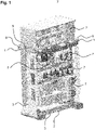
- FIG. 1 12 shows an overall structure of a frame 3 of a brake control device of a rail vehicle (not shown) according to an embodiment of the present invention.
- the brake control device has a number of pneumatic, electrical and electromechanical components 7 which cause the brake control of the rail-bound vehicle.
- the frame 3 has several scaffolding beams 1, 2 according to embodiments of the present invention.
- Fig. 3 shows an empty frame 3 of an embodiment of the present invention.
- the frame 3 has two upper scaffolding beams 1 on its upper side.
- the upper scaffolding beams 1 are identical, ie they have the same shape, and they are provided on the upper side of the frame 3 essentially symmetrically.
- the upper scaffold beams 1 are arranged transversely in the direction of travel of the rail vehicle.
- the frame 3 has exactly one lower scaffolding beam 2 on its lower side, which is arranged in the direction of travel of the rail-bound vehicle. Alternatively, several such lower scaffolding beams 2 can also be provided.
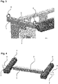
- Fig. 12 shows the top girder 1 according to an embodiment of the present invention.
- the upper scaffold beam 1 has a pneumatic interface 5 .
- the pneumatic interface 5 consists of connection threads.
- the upper scaffolding beam 1 is also suitable for forming a supporting element of the frame 3 .
- the property of the upper scaffolding beam 1 as a supporting element of the frame 3 is realized, for example, in that the upper scaffolding beam 1 has a structure 6 for transporting or lifting the frame 3.
- the structure 6 for transporting or lifting the frame 3 is a transport screw.
- the structure 6 for transporting or lifting the frame may be threaded to receive such a transport screw.
- FIG. 12 shows a lower scaffolding beam 2 according to a further embodiment of the present invention.
- the lower scaffold beam 2 also has a pneumatic interface 5 .
- the pneumatic interface 5 consists of connection threads.
- the lower scaffolding beam 2 is also suitable for forming a load-bearing element of the frame 3 .
- the property of the lower truss 2 as a supporting element of the frame 3 is realized, for example, in that the lower truss 2 is suitable for connecting at least two elements of the frame 3 in such a way that the frame 3 becomes stable. In other words, if the lower scaffolding beam 2 were missing, the frame 3 would not be stable for the intended use and accordingly would not be approved for use.
- the lower scaffolding beam 2 is screwed to the two (transverse) elements of the frame 3 by means of longitudinal screws 8 .
- FIG. 5 shows a prior art frame 3'.
- the pneumatic interface 5' does not have any connecting threads, but instead has screwed pipe connections which are screwed directly onto the frame 3'.
- Pipe fittings of this type can also be provided as pneumatic interfaces in the scaffolding beams of the exemplary embodiments of the present invention.
Landscapes
- Engineering & Computer Science (AREA)
- Transportation (AREA)
- Mechanical Engineering (AREA)
- Automation & Control Theory (AREA)
- Microelectronics & Electronic Packaging (AREA)
- Braking Arrangements (AREA)
- Body Structure For Vehicles (AREA)
- Valves And Accessory Devices For Braking Systems (AREA)
Description
- Die vorliegende Erfindung bezieht sich auf einen Gerüstbalken für einen Rahmen einer Bremssteuereinrichtung eines schienengebundenen Fahrzeugs.
-
Fig. 6 zeigt einen herkömmlichen Rahmen 30 einer pneumatischen Einrichtung 40 in Gestalt einer Bremssteuereinrichtung eines schienengebundenen Fahrzeugs. Dieser herkömmliche Rahmen 30 hat eine separat angebaute Anschlussleiste 20 mit pneumatischen Anschlüssen. Die Befestigung der pneumatischen Anschlussleiste 20 an den Rahmen 30 erfolgt mittels Haltewinkeln und Schraubenverbindungen 80. Die Nachteile dieser Bauformen sind einerseits hohe Beschaffungs- und Montagekosten, da zusätzliche Befestigungs- und Verbindungselemente 80 (z.B. Haltewinkel, Schrauben etc.) benötigt werden. Durch die Notwendigkeit der zusätzlichen Befestigungs- und Verbindungselemente 80 (z.B. Haltewinkel, Schrauben etc.) wird der Einbauraum für die pneumatischen Anschlüsse reduziert. - In diesem Zusammenhang offenbart die
US 2013/0134770 A1 eine Bremssteuereinrichtung mit einem Leitungssitz, der an einem Rahmen befestigt und an den wiederum ein Ventilblock montiert ist. - In ähnlicher Weise offenbart die
DE 10 2008 009217 A1 ein Bremsgerüst mit einer Standardschnittstelle zur pneumatischen Verbindung eines Hauptluftbehälters mit einem Schienenfahrzeug oder mit anderen Modulen des Bremsgerüstes. - Es ist die Aufgabe der vorliegenden Erfindung, einen Gerüstbalken für einen Rahmen einer Bremssteuereinrichtung eines schienengebundenen Fahrzeugs vorzusehen, der die vorstehend geschilderten Nachteile beseitigt. Insbesondere soll der Einbauraum für pneumatische Anschlüsse vergrößert werden und die Montage des Rahmens soll vereinfacht werden, wobei gleichzeitig die Fertigungskosten des Rahmens reduziert werden sollen.
- Diese Aufgabe wird durch einen Gerüstbalken für einen Rahmen einer Bremssteuereinrichtung eines schienengebundenen Fahrzeugs mit den Merkmalen des Anspruchs 1 gelöst. Vorteilhafte Weiterbildungen sind in den abhängigen Ansprüchen angegeben.
- Der Gerüstbalken für einen Rahmen einer Bremssteuereinrichtung eines schienengebundenen Fahrzeugs weist eine pneumatische Schnittstelle auf und ist darüber hinaus geeignet, ein tragendes Element des Rahmens zu bilden, wobei die Eigenschaft des Gerüstbalkens als tragendes Element des Rahmens dadurch verwirklicht ist, dass der Gerüstbalken eine Struktur zum Transportieren oder Heben des Rahmens aufweist. Damit wird ein standardisiertes Grundkonzept für einen Rahmen ermöglicht, der für weitere Projekte verwendet werden kann.
- Durch das Weglassen von zusätzlichen Befestigungs- und Verbindungselemente für die Befestigung der Anschlussleisten kann eine Kosten- und Gewichtsersparnis erzielt werden. Da die relativ schwachen Blechteile bzw. Halter für die Befestigung des Gerüstbalkens nicht mehr vorhanden sind, kann eine Erhöhung der Steifigkeit insbesondere in Fahrtrichtung erzielt werden. Zudem wird der Entwicklungsaufwand optimiert, und die Anordnung, Position und Größe der pneumatischen Anschlüsse kann mit wenig Aufwand projektspezifisch angepasst werden. Es wird eine bessere Zugänglichkeit bei Montage und Wartung erreicht, da im Anschlussbereich keine zusätzliche Rahmenstruktur zum Versteifen notwendig ist. Der Einbauraum für die pneumatischen Anschlüsse ist vergrößert, da die zusätzliche Befestigungs- und Verbindungselemente (z.B. Haltewinkel, Schrauben etc.) entfallen. Die Montage wird zudem erleichtert und benötigt keine komplizierte Vorrichtung.
- Da die Gerüstbalken in der Regel mechanisch bearbeitete Teile sind, ist es möglich die engeren Toleranzen im Gesamtrahmen einzuhalten.
- Das Gesamtgewicht des Rahmens kann durch die Funktionskombination, d.h. Tragende Struktur, pneumatische Schnittstelle und ggf. Transportbohrungen, reduziert werden.
- Im Folgenden wird ein Ausführungsbeispiel der vorliegenden Erfindung anhand der Figuren beschrieben. Es zeigen:
- Fig. 1
- einen Gesamtaufbau eines Rahmen einer Bremssteuerung eines schienengebundenen Fahrzeugs;
- Fig. 2
- einen leeren Rahmen eines Ausführungsbeispiel der vorliegenden Erfindung;
- Fig. 3
- einen Gerüstbalken gemäß einem Ausführungsbeispiel der vorliegenden Erfindung;
- Fig. 4
- einen Gerüstbalken gemäß einem weiteren Ausführungsbeispiel der vorliegenden Erfindung;
- Fig. 5
- einen Abschnitt eines Rahmens des Stands der Technik; und
- Fig. 6
- einen unteren Abschnitt eines Rahmens des Stands der Technik.
-
Fig. 1 zeigt einen Gesamtaufbau eines Rahmens 3 einer Bremssteuereinrichtung eines schienengebundenen Fahrzeugs (nicht gezeigt) gemäß einem Ausführungsbeispiel der vorliegenden Erfindung. Die Bremssteuereinrichtung verfügt über mehrere pneumatische, elektrische und elektromechanische Komponenten 7, die die Bremssteuerung des schienengebundenen Fahrzeugs bewirken. Der Rahmen 3 weist mehrere Gerüstbalken 1, 2 gemäß Ausführungsbeispielen der vorliegenden Erfindung auf. -
Fig. 2 zeigt einen leeren Rahmen 3 eines Ausführungsbeispiels der vorliegenden Erfindung. Der Rahmen 3 hat im bestimmungsgemäßen Gebrauch an seiner oberen Seite zwei obere Gerüstbalken 1. Die oberen Gerüstbalken 1 sind identisch, d.h. sie haben dieselbe Form, und sie sind im Wesentlichen symmetrisch an der oberen Seite des Rahmens 3 vorgesehen. Die oberen Gerüstbalken 1 sind in Fahrtrichtung des schienengebundenen Fahrzeugs quer angeordnet. Ferner hat der Rahmen 3 im bestimmungsgemäßen Gebrauch an seiner unteren Seite exakt einen unteren Gerüstbalken 2, der in Fahrtrichtung des schienengebundenen Fahrzeugs angeordnet ist. Alternativ können auch mehrere derartige, untere Gerüstbalken 2 vorgesehen sein. -
Fig. 3 zeigt den oberen Gerüstbalken 1 gemäß einem Ausführungsbeispiel der vorliegenden Erfindung. Erfindungsgemäß weist der obere Gerüstbalken 1 eine pneumatische Schnittstelle 5 auf. Im dargestellten Ausführungsbeispiel besteht die pneumatische Schnittstelle 5 aus Anschlussgewinden. Der obere Gerüstbalken 1 ist zusätzlich geeignet, ein tragendes Element des Rahmens 3 zu bilden. Die Eigenschaft des oberen Gerüstbalkens 1 als tragendes Element des Rahmens 3 wird zum Beispiel dadurch verwirklicht, dass der obere Gerüstbalken 1 eine Struktur 6 zum Transportieren oder Heben des Rahmens 3 aufweist. Im dargestellten Ausführungsbeispiel ist die Struktur 6 zum Transportieren oder Heben des Rahmens 3 eine Transportschraube. Alternativ kann die Struktur 6 zum Transportieren oder Heben des Rahmens ein Gewinde zur Aufnahme einer solchen Transportschraube sein. -
Fig. 4 zeigt einen unteren Gerüstbalken 2 gemäß einem weiteren Ausführungsbeispiel der vorliegenden Erfindung. Erfindungsgemäß weist auch der untere Gerüstbalken 2 eine pneumatische Schnittstelle 5 auf. Im dargestellten Ausführungsbeispiel besteht die pneumatische Schnittstelle 5 aus Anschlussgewinden. Der untere Gerüstbalken 2 ist zusätzlich geeignet, ein tragendes Element des Rahmens 3 zu bilden. Die Eigenschaft des unteren Gerüstbalkens 2 als tragendes Element des Rahmens 3 wird zum Beispiel dadurch verwirklicht, dass der untere Gerüstbalken 2 geeignet ist, mindestens zwei Elemente des Rahmens 3 so zu verbinden, dass der Rahmen 3 stabil wird. Mit anderen Worten wäre der Rahmen 3, wenn der untere Gerüstbalken 2 fehlen würde, für den bestimmungsgemäßen Gebrauch nicht stabil und dementsprechend nicht zur Verwendung zugelassen. Im dargestellten Ausführungsbeispiel ist der untere Gerüstbalken 2 durch Längsschrauben 8 an die beiden (querverlaufenden) Elemente des Rahmens 3 geschraubt. -
Fig. 5 zeigt einen Rahmen 3' des Stands der Technik. In diesem Beispiel hat die pneumatische Schnittstelle 5' keine Anschlussgewinde, sondern Rohrverschraubungen, die direkt auf den Rahmen 3' geschraubt sind. Derartige Rohrverschraubungen können auch als pneumatische Schnittstellen bei den Gerüstbalken der Ausführungsbeispiele der vorliegenden Erfindung vorgsehen sein. - Insgesamt können durch die vorliegende Erfindung die folgenden Vorteile erzielt werden:
- ein Standardisiertes Grundkonzept, das für weitere Projekte verwendet werden kann
- eine Optimierung des Entwicklungsaufwandes, da Anordnung, Position und Größe der pneumatischen Anschlüsse mit wenig Aufwand projektspezifisch angepasst werden können
- Die Gerüstbalken können als tragende Rahmenstrukturen verwendet werden.
- Da die beiden Gerüstbalken mechanisch bearbeitete Teile sind, ist es möglich engere Toleranzen im Gesamtrahmen einzuhalten.
- eine Kosten- und Gewichtsersparnis durch Weglassen von Befestigungs- und Verbindungselementen für die Befestigung der Gerüstbalken
- eine Erhöhung der Steifigkeit insbesondere in Fahrtrichtung, da die schwachen Blechteile bzw. Halter für die Befestigung des unteren Gerüstbalkens nicht vorhanden sind
- einer verbesserten Zugänglichkeit bei Montage und Wartung, da im Anschlussbereich keine zusätzliche Rahmenstruktur zum Versteifen notwendig ist.
- Mehr Einbauraum für die pneumatischen Anschlüsse, da die zusätzliche Befestigungs- und Verbindungselemente (z.B. Haltewinkel, Schrauben etc.) entfallen
- Leichte und schnelle Montage ohne komplizierte Vorrichtung
- Die Anhebe- bzw. Transportbohrungen sind in dem oberen Gerüstbalken integriert.
- Der obere Gerüstbalken kann bei einer symmetrischen Ausführung rechts oder links verwendet werden.
- Reduzierung des Gesamtgewichtes durch Funktionskombination (d.h. tragende Struktur + pneumatische Anschlüsse +Transportbohrungen)
- Die vorliegende Erfindung ist nicht auf die dargestellten Ausführungsbeispiele beschränkt, sondern umfasst Änderungen und Abwandlungen innerhalb des Umfangs der beigefügten Ansprüche.
-
- 1
- Gerüstbalken (oberer Gerüstbalken)
- 2
- Gerüstbalken (unterer Gerüstbalken)
- 3, 3'
- Rahmen
- 5, 5'
- pneumatische Schnittstelle
- 6
- Struktur zum Transportieren oder Heben des Rahmens
- 7
- pneumatische, elektrische und elektromechanische Komponenten
- 8
- Längsschraube
Claims (11)
- Gerüstbalken (1, 2) für einen Rahmen (3, 3') einer Bremssteuereinrichtung eines schienengebundenen Fahrzeugs,
dadurch gekennzeichnet, dassder Gerüstbalken (1, 2) eine pneumatische Schnittstelle (5, 5') aufweist und geeignet ist, ein tragendes Element des Rahmens (3, 3') zu bilden,wobei die Eigenschaft des Gerüstbalkens (1) als tragendes Element des Rahmens (3, 3') dadurch verwirklicht ist, dass der Gerüstbalken (1) eine Struktur (6) zum Transportieren oder Heben des Rahmens (3, 3') aufweist. - Gerüstbalken (1) gemäß Anspruch 1,
wobei die Struktur (6) zum Transportieren oder Heben des Rahmens (3, 3') eine Transportschraube oder ein Gewinde zur Aufnahme einer solchen Transportschraube ist. - Gerüstbalken (2) gemäß Anspruch 1 oder 2,
wobei die Eigenschaft des Gerüstbalkens (2) als tragendes Element des Rahmens (3, 3') dadurch verwirklicht ist, dass der Gerüstbalken (2) geeignet ist, mindestens zwei Elemente des Rahmens (3, 3') so zu verbinden, dass der Rahmen (3, 3') stabil wird. - Gerüstbalken (1, 2) gemäß einem der vorherigen Ansprüche,
wobei die Bremssteuereinrichtung ein Bremssteuermodul für das schienengebundene Fahrzeug ist. - Rahmen (3, 3') für eine Bremssteuereinrichtung eines schienengebundenen Fahrzeugs,
gekennzeichnet durch
mindestens einen Gerüstbalken (1, 2) gemäß einem der vorherigen Ansprüche. - Rahmen (3') gemäß Anspruch 5,
wobei die pneumatische Schnittstelle (5') Rohrverschraubungen aufweist. - Rahmen (3, 3') gemäß Anspruch 5 oder 6,
wobei mindestens ein Gerüstbalken (1) nach Anspruch 1 im bestimmungsgemäßen Gebrauch an einer oberen Seite des Rahmens (3, 3') vorgesehen ist. - Rahmen (3, 3') gemäß Anspruch 7,
wobei zwei identische Gerüstbalken (1) nach Anspruch 1 im bestimmungsgemäßen Gebrauch an einer oberen Seite des Rahmens (3, 3') vorgesehen sind. - Rahmen (3, 3') gemäß Anspruch 8,
wobei die beiden Gerüstbalken (1) nach Anspruch 1 im Wesentlichen symmetrisch an der oberen Seite des Rahmens (3, 3') vorgesehen sind. - Rahmen (3, 3') gemäß einem der Ansprüche 5 bis 9,
wobei mindestens ein Gerüstbalken (2) nach Anspruch 3 im bestimmungsgemäßen Gebrauch an einer unteren Seite des Rahmens (3, 3') vorgesehen ist. - Rahmen (3, 3') gemäß Anspruch 10,
wobei der Gerüstbalken (2) nach Anspruch 3 im bestimmungsgemäßen Gebrauch in Fahrtrichtung des schienengebundenen Fahrzeugs angeordnet ist.
Applications Claiming Priority (2)
| Application Number | Priority Date | Filing Date | Title |
|---|---|---|---|
| DE102016117497.1A DE102016117497A1 (de) | 2016-09-16 | 2016-09-16 | Gerüstbalken für einen Rahmen einer Bremssteuereinrichtung eines schienengebundenen Fahrzeugs |
| PCT/EP2017/071025 WO2018050397A1 (de) | 2016-09-16 | 2017-08-21 | Gerüstbalken für einen rahmen einer bremssteuereinrichtung eines schienengebundenen fahrzeugs |
Publications (3)
| Publication Number | Publication Date |
|---|---|
| EP3512750A1 EP3512750A1 (de) | 2019-07-24 |
| EP3512750B1 true EP3512750B1 (de) | 2022-10-12 |
| EP3512750B2 EP3512750B2 (de) | 2025-12-10 |
Family
ID=59699684
Family Applications (1)
| Application Number | Title | Priority Date | Filing Date |
|---|---|---|---|
| EP17757512.3A Active EP3512750B2 (de) | 2016-09-16 | 2017-08-21 | Rahmen für eine bremssteuereinrichtung eines schienengebundenen fahrzeugs |
Country Status (3)
| Country | Link |
|---|---|
| EP (1) | EP3512750B2 (de) |
| DE (1) | DE102016117497A1 (de) |
| WO (1) | WO2018050397A1 (de) |
Citations (11)
| Publication number | Priority date | Publication date | Assignee | Title |
|---|---|---|---|---|
| US5025734A (en) | 1990-05-03 | 1991-06-25 | Westinghouse Air Brake Company | Locomotive equipment carriage |
| KR19990074977A (ko) | 1998-03-16 | 1999-10-05 | 이재영 | 철도차량용 압축공기 발생장치 |
| EP0767313B1 (de) | 1995-10-03 | 2001-02-07 | Smc Corporation | Verfahren zum Anbringen einer Flüssigkeitsvorrichtung an einem Rahmenelement |
| EP1288095A2 (de) | 2001-08-31 | 2003-03-05 | Günther Dipl.-Ing.(TU) Winkle | Bremsdiagnose für Schienen- und Strassenfahrzeuge |
| WO2008049204A1 (en) | 2006-10-23 | 2008-05-02 | Hydrogenics Corporation | Frame system and electrochemical cell system having the frame system |
| DE102008009217A1 (de) | 2008-02-12 | 2009-08-20 | Siemens Aktiengesellschaft | Modulares Bremsgerüst |
| CN202320375U (zh) | 2011-12-30 | 2012-07-11 | 克诺尔车辆设备(苏州)有限公司 | 空气制动控制柜及具有该控制柜的电力机车 |
| US20130134770A1 (en) | 2011-11-30 | 2013-05-30 | Mitsubishi Heavy Industries, Ltd. | Brake control device |
| DE102012206663A1 (de) | 2012-04-23 | 2013-10-24 | Siemens Aktiengesellschaft | Strukturstabile Anordnung und Verfahren zur Bildung einer strukturstabilen Anordnung. |
| WO2015106803A1 (de) | 2014-01-15 | 2015-07-23 | Siemens Aktiengesellschaft | Druckluftgerüst einer elektrischen lokomotive |
| CN204701625U (zh) | 2015-06-16 | 2015-10-14 | 中国北车集团大连机车车辆有限公司 | 机车集成式空气制动柜 |
-
2016
- 2016-09-16 DE DE102016117497.1A patent/DE102016117497A1/de active Pending
-
2017
- 2017-08-21 WO PCT/EP2017/071025 patent/WO2018050397A1/de not_active Ceased
- 2017-08-21 EP EP17757512.3A patent/EP3512750B2/de active Active
Patent Citations (11)
| Publication number | Priority date | Publication date | Assignee | Title |
|---|---|---|---|---|
| US5025734A (en) | 1990-05-03 | 1991-06-25 | Westinghouse Air Brake Company | Locomotive equipment carriage |
| EP0767313B1 (de) | 1995-10-03 | 2001-02-07 | Smc Corporation | Verfahren zum Anbringen einer Flüssigkeitsvorrichtung an einem Rahmenelement |
| KR19990074977A (ko) | 1998-03-16 | 1999-10-05 | 이재영 | 철도차량용 압축공기 발생장치 |
| EP1288095A2 (de) | 2001-08-31 | 2003-03-05 | Günther Dipl.-Ing.(TU) Winkle | Bremsdiagnose für Schienen- und Strassenfahrzeuge |
| WO2008049204A1 (en) | 2006-10-23 | 2008-05-02 | Hydrogenics Corporation | Frame system and electrochemical cell system having the frame system |
| DE102008009217A1 (de) | 2008-02-12 | 2009-08-20 | Siemens Aktiengesellschaft | Modulares Bremsgerüst |
| US20130134770A1 (en) | 2011-11-30 | 2013-05-30 | Mitsubishi Heavy Industries, Ltd. | Brake control device |
| CN202320375U (zh) | 2011-12-30 | 2012-07-11 | 克诺尔车辆设备(苏州)有限公司 | 空气制动控制柜及具有该控制柜的电力机车 |
| DE102012206663A1 (de) | 2012-04-23 | 2013-10-24 | Siemens Aktiengesellschaft | Strukturstabile Anordnung und Verfahren zur Bildung einer strukturstabilen Anordnung. |
| WO2015106803A1 (de) | 2014-01-15 | 2015-07-23 | Siemens Aktiengesellschaft | Druckluftgerüst einer elektrischen lokomotive |
| CN204701625U (zh) | 2015-06-16 | 2015-10-14 | 中国北车集团大连机车车辆有限公司 | 机车集成式空气制动柜 |
Also Published As
| Publication number | Publication date |
|---|---|
| EP3512750B2 (de) | 2025-12-10 |
| EP3512750A1 (de) | 2019-07-24 |
| WO2018050397A1 (de) | 2018-03-22 |
| DE102016117497A1 (de) | 2018-03-22 |
Similar Documents
| Publication | Publication Date | Title |
|---|---|---|
| EP2240356B1 (de) | Fahrwerkstraverse für ein schienenfahrzeug | |
| EP2822831B1 (de) | Strukturstabile anordnung und verfahren zur bildung einer strukturstabilen anordnung | |
| DE19536460A1 (de) | Teilrahmenbaugruppe für ein Fahrzeug | |
| DE102017127064A1 (de) | Batterierahmen | |
| EP3696056B1 (de) | Fahrzeug-chassis-modul mit fahrzeug-achse und anschlussknoten | |
| EP3197741A1 (de) | Modulares system zur befestigung einer unterflurkomponente an unterschiedlichen wagenkästen, verfahren zum montieren einer unterflurkomponente an einem wagenkasten, und schienenfahrzeugflotte | |
| EP3696054B1 (de) | Modular aufgebautes fahrzeug-chassis mit hinterem rahmenüberhang | |
| DE102014213098A1 (de) | Federträgerarm | |
| EP3513469B1 (de) | Elektrische einheit für ein schienengebundenes fahrzeug | |
| EP3512750B1 (de) | Gerüstbalken für einen rahmen einer bremssteuereinrichtung eines schienengebundenen fahrzeugs | |
| EP2986459B1 (de) | Längslenker | |
| EP3494023B1 (de) | Langträgeranordnung für einen wagenkasten eines fahrzeugs | |
| DE102005055586A1 (de) | Vierpunktlenker zur Anbindung einer Starrachse an den Rahmen eines Fahrzeuges, insbesondere eines Nutzfahrzeuges | |
| DE202015103767U1 (de) | Querlenker für ein Kraftfahrzeug | |
| DE3120775C2 (de) | Flanschkonstruktion für die Schraubverbindung zwischen einem Anhänger-Fahrgestell und dem Rahmen des Anhänger-Aufbaues | |
| EP3456559A1 (de) | Blattfeder zur verwendung in verbindung mit einer radaufhängung eines fahrzeuges | |
| DE102011010201A1 (de) | Schlussquerträger für ein Nutzfahrzeug | |
| DE19622771C2 (de) | Schwingungsdämpfer | |
| DE102015212766A1 (de) | Querlenker für ein Kraftfahrzeug | |
| DE112014005750B4 (de) | Aufhängevorrichtung für Fahrzeuge | |
| DE102018006572B4 (de) | Fahrzeugaufhängungsanordnung für mindestens eine Radachse | |
| EP3516669B1 (de) | Transformator | |
| DE102018006863A1 (de) | Radträger für eine Hinterachsaufhängung eines Nutzfahrzeugs | |
| EP2900536B1 (de) | Schienenfahrzeug mit einer konsole zur befestigung von dachaufbauten | |
| DE202007010799U1 (de) | Transporthilfe für Warmwasserspeicher |
Legal Events
| Date | Code | Title | Description |
|---|---|---|---|
| STAA | Information on the status of an ep patent application or granted ep patent |
Free format text: STATUS: UNKNOWN |
|
| STAA | Information on the status of an ep patent application or granted ep patent |
Free format text: STATUS: THE INTERNATIONAL PUBLICATION HAS BEEN MADE |
|
| PUAI | Public reference made under article 153(3) epc to a published international application that has entered the european phase |
Free format text: ORIGINAL CODE: 0009012 |
|
| STAA | Information on the status of an ep patent application or granted ep patent |
Free format text: STATUS: REQUEST FOR EXAMINATION WAS MADE |
|
| 17P | Request for examination filed |
Effective date: 20190416 |
|
| AK | Designated contracting states |
Kind code of ref document: A1 Designated state(s): AL AT BE BG CH CY CZ DE DK EE ES FI FR GB GR HR HU IE IS IT LI LT LU LV MC MK MT NL NO PL PT RO RS SE SI SK SM TR |
|
| AX | Request for extension of the european patent |
Extension state: BA ME |
|
| DAV | Request for validation of the european patent (deleted) | ||
| DAX | Request for extension of the european patent (deleted) | ||
| GRAP | Despatch of communication of intention to grant a patent |
Free format text: ORIGINAL CODE: EPIDOSNIGR1 |
|
| STAA | Information on the status of an ep patent application or granted ep patent |
Free format text: STATUS: GRANT OF PATENT IS INTENDED |
|
| INTG | Intention to grant announced |
Effective date: 20220324 |
|
| GRAS | Grant fee paid |
Free format text: ORIGINAL CODE: EPIDOSNIGR3 |
|
| GRAA | (expected) grant |
Free format text: ORIGINAL CODE: 0009210 |
|
| STAA | Information on the status of an ep patent application or granted ep patent |
Free format text: STATUS: THE PATENT HAS BEEN GRANTED |
|
| AK | Designated contracting states |
Kind code of ref document: B1 Designated state(s): AL AT BE BG CH CY CZ DE DK EE ES FI FR GB GR HR HU IE IS IT LI LT LU LV MC MK MT NL NO PL PT RO RS SE SI SK SM TR |
|
| REG | Reference to a national code |
Ref country code: GB Ref legal event code: FG4D Free format text: NOT ENGLISH |
|
| REG | Reference to a national code |
Ref country code: CH Ref legal event code: EP |
|
| REG | Reference to a national code |
Ref country code: DE Ref legal event code: R096 Ref document number: 502017013953 Country of ref document: DE |
|
| REG | Reference to a national code |
Ref country code: IE Ref legal event code: FG4D Free format text: LANGUAGE OF EP DOCUMENT: GERMAN |
|
| REG | Reference to a national code |
Ref country code: AT Ref legal event code: REF Ref document number: 1523998 Country of ref document: AT Kind code of ref document: T Effective date: 20221115 |
|
| REG | Reference to a national code |
Ref country code: LT Ref legal event code: MG9D |
|
| REG | Reference to a national code |
Ref country code: NL Ref legal event code: MP Effective date: 20221012 |
|
| PG25 | Lapsed in a contracting state [announced via postgrant information from national office to epo] |
Ref country code: NL Free format text: LAPSE BECAUSE OF FAILURE TO SUBMIT A TRANSLATION OF THE DESCRIPTION OR TO PAY THE FEE WITHIN THE PRESCRIBED TIME-LIMIT Effective date: 20221012 |
|
| PG25 | Lapsed in a contracting state [announced via postgrant information from national office to epo] |
Ref country code: SE Free format text: LAPSE BECAUSE OF FAILURE TO SUBMIT A TRANSLATION OF THE DESCRIPTION OR TO PAY THE FEE WITHIN THE PRESCRIBED TIME-LIMIT Effective date: 20221012 Ref country code: PT Free format text: LAPSE BECAUSE OF FAILURE TO SUBMIT A TRANSLATION OF THE DESCRIPTION OR TO PAY THE FEE WITHIN THE PRESCRIBED TIME-LIMIT Effective date: 20230213 Ref country code: NO Free format text: LAPSE BECAUSE OF FAILURE TO SUBMIT A TRANSLATION OF THE DESCRIPTION OR TO PAY THE FEE WITHIN THE PRESCRIBED TIME-LIMIT Effective date: 20230112 Ref country code: LT Free format text: LAPSE BECAUSE OF FAILURE TO SUBMIT A TRANSLATION OF THE DESCRIPTION OR TO PAY THE FEE WITHIN THE PRESCRIBED TIME-LIMIT Effective date: 20221012 Ref country code: FI Free format text: LAPSE BECAUSE OF FAILURE TO SUBMIT A TRANSLATION OF THE DESCRIPTION OR TO PAY THE FEE WITHIN THE PRESCRIBED TIME-LIMIT Effective date: 20221012 Ref country code: ES Free format text: LAPSE BECAUSE OF FAILURE TO SUBMIT A TRANSLATION OF THE DESCRIPTION OR TO PAY THE FEE WITHIN THE PRESCRIBED TIME-LIMIT Effective date: 20221012 |
|
| PG25 | Lapsed in a contracting state [announced via postgrant information from national office to epo] |
Ref country code: RS Free format text: LAPSE BECAUSE OF FAILURE TO SUBMIT A TRANSLATION OF THE DESCRIPTION OR TO PAY THE FEE WITHIN THE PRESCRIBED TIME-LIMIT Effective date: 20221012 Ref country code: PL Free format text: LAPSE BECAUSE OF FAILURE TO SUBMIT A TRANSLATION OF THE DESCRIPTION OR TO PAY THE FEE WITHIN THE PRESCRIBED TIME-LIMIT Effective date: 20221012 Ref country code: LV Free format text: LAPSE BECAUSE OF FAILURE TO SUBMIT A TRANSLATION OF THE DESCRIPTION OR TO PAY THE FEE WITHIN THE PRESCRIBED TIME-LIMIT Effective date: 20221012 Ref country code: IS Free format text: LAPSE BECAUSE OF FAILURE TO SUBMIT A TRANSLATION OF THE DESCRIPTION OR TO PAY THE FEE WITHIN THE PRESCRIBED TIME-LIMIT Effective date: 20230212 Ref country code: HR Free format text: LAPSE BECAUSE OF FAILURE TO SUBMIT A TRANSLATION OF THE DESCRIPTION OR TO PAY THE FEE WITHIN THE PRESCRIBED TIME-LIMIT Effective date: 20221012 Ref country code: GR Free format text: LAPSE BECAUSE OF FAILURE TO SUBMIT A TRANSLATION OF THE DESCRIPTION OR TO PAY THE FEE WITHIN THE PRESCRIBED TIME-LIMIT Effective date: 20230113 |
|
| P01 | Opt-out of the competence of the unified patent court (upc) registered |
Effective date: 20230523 |
|
| REG | Reference to a national code |
Ref country code: DE Ref legal event code: R026 Ref document number: 502017013953 Country of ref document: DE |
|
| PLBI | Opposition filed |
Free format text: ORIGINAL CODE: 0009260 |
|
| PLAB | Opposition data, opponent's data or that of the opponent's representative modified |
Free format text: ORIGINAL CODE: 0009299OPPO |
|
| PLAX | Notice of opposition and request to file observation + time limit sent |
Free format text: ORIGINAL CODE: EPIDOSNOBS2 |
|
| PG25 | Lapsed in a contracting state [announced via postgrant information from national office to epo] |
Ref country code: SM Free format text: LAPSE BECAUSE OF FAILURE TO SUBMIT A TRANSLATION OF THE DESCRIPTION OR TO PAY THE FEE WITHIN THE PRESCRIBED TIME-LIMIT Effective date: 20221012 Ref country code: RO Free format text: LAPSE BECAUSE OF FAILURE TO SUBMIT A TRANSLATION OF THE DESCRIPTION OR TO PAY THE FEE WITHIN THE PRESCRIBED TIME-LIMIT Effective date: 20221012 Ref country code: EE Free format text: LAPSE BECAUSE OF FAILURE TO SUBMIT A TRANSLATION OF THE DESCRIPTION OR TO PAY THE FEE WITHIN THE PRESCRIBED TIME-LIMIT Effective date: 20221012 Ref country code: DK Free format text: LAPSE BECAUSE OF FAILURE TO SUBMIT A TRANSLATION OF THE DESCRIPTION OR TO PAY THE FEE WITHIN THE PRESCRIBED TIME-LIMIT Effective date: 20221012 Ref country code: CZ Free format text: LAPSE BECAUSE OF FAILURE TO SUBMIT A TRANSLATION OF THE DESCRIPTION OR TO PAY THE FEE WITHIN THE PRESCRIBED TIME-LIMIT Effective date: 20221012 |
|
| 26 | Opposition filed |
Opponent name: SIEMENS MOBILITY GMBH Effective date: 20230706 |
|
| R26 | Opposition filed (corrected) |
Opponent name: SIEMENS MOBILITY GMBH Effective date: 20230706 |
|
| PG25 | Lapsed in a contracting state [announced via postgrant information from national office to epo] |
Ref country code: SK Free format text: LAPSE BECAUSE OF FAILURE TO SUBMIT A TRANSLATION OF THE DESCRIPTION OR TO PAY THE FEE WITHIN THE PRESCRIBED TIME-LIMIT Effective date: 20221012 Ref country code: AL Free format text: LAPSE BECAUSE OF FAILURE TO SUBMIT A TRANSLATION OF THE DESCRIPTION OR TO PAY THE FEE WITHIN THE PRESCRIBED TIME-LIMIT Effective date: 20221012 |
|
| PLBB | Reply of patent proprietor to notice(s) of opposition received |
Free format text: ORIGINAL CODE: EPIDOSNOBS3 |
|
| PG25 | Lapsed in a contracting state [announced via postgrant information from national office to epo] |
Ref country code: SI Free format text: LAPSE BECAUSE OF FAILURE TO SUBMIT A TRANSLATION OF THE DESCRIPTION OR TO PAY THE FEE WITHIN THE PRESCRIBED TIME-LIMIT Effective date: 20221012 |
|
| PG25 | Lapsed in a contracting state [announced via postgrant information from national office to epo] |
Ref country code: MC Free format text: LAPSE BECAUSE OF FAILURE TO SUBMIT A TRANSLATION OF THE DESCRIPTION OR TO PAY THE FEE WITHIN THE PRESCRIBED TIME-LIMIT Effective date: 20221012 |
|
| REG | Reference to a national code |
Ref country code: CH Ref legal event code: PL |
|
| PG25 | Lapsed in a contracting state [announced via postgrant information from national office to epo] |
Ref country code: MC Free format text: LAPSE BECAUSE OF FAILURE TO SUBMIT A TRANSLATION OF THE DESCRIPTION OR TO PAY THE FEE WITHIN THE PRESCRIBED TIME-LIMIT Effective date: 20221012 |
|
| PG25 | Lapsed in a contracting state [announced via postgrant information from national office to epo] |
Ref country code: LU Free format text: LAPSE BECAUSE OF NON-PAYMENT OF DUE FEES Effective date: 20230821 |
|
| GBPC | Gb: european patent ceased through non-payment of renewal fee |
Effective date: 20230821 |
|
| PG25 | Lapsed in a contracting state [announced via postgrant information from national office to epo] |
Ref country code: LU Free format text: LAPSE BECAUSE OF NON-PAYMENT OF DUE FEES Effective date: 20230821 Ref country code: CH Free format text: LAPSE BECAUSE OF NON-PAYMENT OF DUE FEES Effective date: 20230831 |
|
| REG | Reference to a national code |
Ref country code: BE Ref legal event code: MM Effective date: 20230831 |
|
| REG | Reference to a national code |
Ref country code: IE Ref legal event code: MM4A |
|
| PG25 | Lapsed in a contracting state [announced via postgrant information from national office to epo] |
Ref country code: IE Free format text: LAPSE BECAUSE OF NON-PAYMENT OF DUE FEES Effective date: 20230821 |
|
| PG25 | Lapsed in a contracting state [announced via postgrant information from national office to epo] |
Ref country code: GB Free format text: LAPSE BECAUSE OF NON-PAYMENT OF DUE FEES Effective date: 20230821 |
|
| PG25 | Lapsed in a contracting state [announced via postgrant information from national office to epo] |
Ref country code: IE Free format text: LAPSE BECAUSE OF NON-PAYMENT OF DUE FEES Effective date: 20230821 Ref country code: GB Free format text: LAPSE BECAUSE OF NON-PAYMENT OF DUE FEES Effective date: 20230821 Ref country code: FR Free format text: LAPSE BECAUSE OF NON-PAYMENT OF DUE FEES Effective date: 20230831 |
|
| PG25 | Lapsed in a contracting state [announced via postgrant information from national office to epo] |
Ref country code: BE Free format text: LAPSE BECAUSE OF NON-PAYMENT OF DUE FEES Effective date: 20230831 |
|
| REG | Reference to a national code |
Ref country code: AT Ref legal event code: MM01 Ref document number: 1523998 Country of ref document: AT Kind code of ref document: T Effective date: 20230821 |
|
| PG25 | Lapsed in a contracting state [announced via postgrant information from national office to epo] |
Ref country code: AT Free format text: LAPSE BECAUSE OF NON-PAYMENT OF DUE FEES Effective date: 20230821 |
|
| PG25 | Lapsed in a contracting state [announced via postgrant information from national office to epo] |
Ref country code: AT Free format text: LAPSE BECAUSE OF NON-PAYMENT OF DUE FEES Effective date: 20230821 |
|
| PG25 | Lapsed in a contracting state [announced via postgrant information from national office to epo] |
Ref country code: BG Free format text: LAPSE BECAUSE OF FAILURE TO SUBMIT A TRANSLATION OF THE DESCRIPTION OR TO PAY THE FEE WITHIN THE PRESCRIBED TIME-LIMIT Effective date: 20221012 |
|
| PG25 | Lapsed in a contracting state [announced via postgrant information from national office to epo] |
Ref country code: BG Free format text: LAPSE BECAUSE OF FAILURE TO SUBMIT A TRANSLATION OF THE DESCRIPTION OR TO PAY THE FEE WITHIN THE PRESCRIBED TIME-LIMIT Effective date: 20221012 |
|
| PG25 | Lapsed in a contracting state [announced via postgrant information from national office to epo] |
Ref country code: CY Free format text: LAPSE BECAUSE OF FAILURE TO SUBMIT A TRANSLATION OF THE DESCRIPTION OR TO PAY THE FEE WITHIN THE PRESCRIBED TIME-LIMIT; INVALID AB INITIO Effective date: 20170821 |
|
| PG25 | Lapsed in a contracting state [announced via postgrant information from national office to epo] |
Ref country code: HU Free format text: LAPSE BECAUSE OF FAILURE TO SUBMIT A TRANSLATION OF THE DESCRIPTION OR TO PAY THE FEE WITHIN THE PRESCRIBED TIME-LIMIT; INVALID AB INITIO Effective date: 20170821 |
|
| REG | Reference to a national code |
Ref country code: CH Ref legal event code: W10 Free format text: ST27 STATUS EVENT CODE: U-0-0-W10-W00 (AS PROVIDED BY THE NATIONAL OFFICE) Effective date: 20251006 |
|
| PGFP | Annual fee paid to national office [announced via postgrant information from national office to epo] |
Ref country code: DE Payment date: 20250827 Year of fee payment: 9 |
|
| PGFP | Annual fee paid to national office [announced via postgrant information from national office to epo] |
Ref country code: IT Payment date: 20250821 Year of fee payment: 9 |
|
| PUAH | Patent maintained in amended form |
Free format text: ORIGINAL CODE: 0009272 |
|
| STAA | Information on the status of an ep patent application or granted ep patent |
Free format text: STATUS: PATENT MAINTAINED AS AMENDED |
|
| REG | Reference to a national code |
Ref country code: CH Ref legal event code: M12 Free format text: ST27 STATUS EVENT CODE: U-0-0-M10-M12 (AS PROVIDED BY THE NATIONAL OFFICE) Effective date: 20251112 |
|
| 27A | Patent maintained in amended form |
Effective date: 20251210 |
|
| AK | Designated contracting states |
Kind code of ref document: B2 Designated state(s): AL AT BE BG CH CY CZ DE DK EE ES FI FR GB GR HR HU IE IS IT LI LT LU LV MC MK MT NL NO PL PT RO RS SE SI SK SM TR |
|
| REG | Reference to a national code |
Ref country code: DE Ref legal event code: R102 Ref document number: 502017013953 Country of ref document: DE |
|
| PG25 | Lapsed in a contracting state [announced via postgrant information from national office to epo] |
Ref country code: TR Free format text: LAPSE BECAUSE OF FAILURE TO SUBMIT A TRANSLATION OF THE DESCRIPTION OR TO PAY THE FEE WITHIN THE PRESCRIBED TIME-LIMIT Effective date: 20221012 |