EP3512674B1 - Kettengetriebener diamantdrahtschneider - Google Patents
Kettengetriebener diamantdrahtschneider Download PDFInfo
- Publication number
- EP3512674B1 EP3512674B1 EP17851598.7A EP17851598A EP3512674B1 EP 3512674 B1 EP3512674 B1 EP 3512674B1 EP 17851598 A EP17851598 A EP 17851598A EP 3512674 B1 EP3512674 B1 EP 3512674B1
- Authority
- EP
- European Patent Office
- Prior art keywords
- diamond wire
- chain
- movable pulley
- cutter
- wire saw
- Prior art date
- Legal status (The legal status is an assumption and is not a legal conclusion. Google has not performed a legal analysis and makes no representation as to the accuracy of the status listed.)
- Active
Links
Images


Classifications
-
- B—PERFORMING OPERATIONS; TRANSPORTING
- B23—MACHINE TOOLS; METAL-WORKING NOT OTHERWISE PROVIDED FOR
- B23D—PLANING; SLOTTING; SHEARING; BROACHING; SAWING; FILING; SCRAPING; LIKE OPERATIONS FOR WORKING METAL BY REMOVING MATERIAL, NOT OTHERWISE PROVIDED FOR
- B23D57/00—Sawing machines or sawing devices not covered by one of the preceding groups B23D45/00 - B23D55/00
- B23D57/003—Sawing machines or sawing devices working with saw wires, characterised only by constructional features of particular parts
- B23D57/0061—Sawing machines or sawing devices working with saw wires, characterised only by constructional features of particular parts of devices for guiding or feeding saw wires
-
- B—PERFORMING OPERATIONS; TRANSPORTING
- B23—MACHINE TOOLS; METAL-WORKING NOT OTHERWISE PROVIDED FOR
- B23D—PLANING; SLOTTING; SHEARING; BROACHING; SAWING; FILING; SCRAPING; LIKE OPERATIONS FOR WORKING METAL BY REMOVING MATERIAL, NOT OTHERWISE PROVIDED FOR
- B23D57/00—Sawing machines or sawing devices not covered by one of the preceding groups B23D45/00 - B23D55/00
- B23D57/003—Sawing machines or sawing devices working with saw wires, characterised only by constructional features of particular parts
- B23D57/0053—Sawing machines or sawing devices working with saw wires, characterised only by constructional features of particular parts of drives for saw wires; of wheel mountings; of wheels
-
- B—PERFORMING OPERATIONS; TRANSPORTING
- B23—MACHINE TOOLS; METAL-WORKING NOT OTHERWISE PROVIDED FOR
- B23D—PLANING; SLOTTING; SHEARING; BROACHING; SAWING; FILING; SCRAPING; LIKE OPERATIONS FOR WORKING METAL BY REMOVING MATERIAL, NOT OTHERWISE PROVIDED FOR
- B23D57/00—Sawing machines or sawing devices not covered by one of the preceding groups B23D45/00 - B23D55/00
- B23D57/003—Sawing machines or sawing devices working with saw wires, characterised only by constructional features of particular parts
- B23D57/0069—Sawing machines or sawing devices working with saw wires, characterised only by constructional features of particular parts of devices for tensioning saw wires
-
- B—PERFORMING OPERATIONS; TRANSPORTING
- B23—MACHINE TOOLS; METAL-WORKING NOT OTHERWISE PROVIDED FOR
- B23D—PLANING; SLOTTING; SHEARING; BROACHING; SAWING; FILING; SCRAPING; LIKE OPERATIONS FOR WORKING METAL BY REMOVING MATERIAL, NOT OTHERWISE PROVIDED FOR
- B23D57/00—Sawing machines or sawing devices not covered by one of the preceding groups B23D45/00 - B23D55/00
- B23D57/0084—Sawing machines or sawing devices not covered by one of the preceding groups B23D45/00 - B23D55/00 specially adapted for sawing under water or at places accessible with difficulty
-
- B—PERFORMING OPERATIONS; TRANSPORTING
- B23—MACHINE TOOLS; METAL-WORKING NOT OTHERWISE PROVIDED FOR
- B23D—PLANING; SLOTTING; SHEARING; BROACHING; SAWING; FILING; SCRAPING; LIKE OPERATIONS FOR WORKING METAL BY REMOVING MATERIAL, NOT OTHERWISE PROVIDED FOR
- B23D61/00—Tools for sawing machines or sawing devices; Clamping devices for these tools
- B23D61/18—Sawing tools of special type, e.g. wire saw strands, saw blades or saw wire equipped with diamonds or other abrasive particles in selected individual positions
- B23D61/185—Saw wires; Saw cables; Twisted saw strips
-
- B—PERFORMING OPERATIONS; TRANSPORTING
- B28—WORKING CEMENT, CLAY, OR STONE
- B28D—WORKING STONE OR STONE-LIKE MATERIALS
- B28D5/00—Fine working of gems, jewels, crystals, e.g. of semiconductor material; apparatus or devices therefor
- B28D5/04—Fine working of gems, jewels, crystals, e.g. of semiconductor material; apparatus or devices therefor by tools other than rotary type, e.g. reciprocating tools
- B28D5/045—Fine working of gems, jewels, crystals, e.g. of semiconductor material; apparatus or devices therefor by tools other than rotary type, e.g. reciprocating tools by cutting with wires or closed-loop blades
Definitions
- cutting is accomplished using a pulley system and guide wheels.
- This technology is mainly used on shore and has the disadvantage that for large sections, the guide wheels will need to be re-positioned and the wire will have to be shortened at regular intervals through the cutting operation.
- cutting is accomplished using a cart with diamond wire mounted on the cart.
- diamond wire mounted on the cart.
- this technology will not allow for cuts on a straight or inverse curvature surface. Further it requires a track, custom built to the diameter of the section to be cut.
- the apparatus includes a shaft module including a cylindrical shaft including a first cavity configured to receive the pile.
- the apparatus also includes a cutting module coupled to the shaft module, the cutting module including a second cavity configured to receive the pile, clamps configured to clamp onto the pile, and a saw configured to cut the pile.
- the apparatus also includes a drilling module coupled to the cutting module, the drilling module including blades to burrow into an earth surface.
- Prior art document US 2009/266552 A1 discloses a diamond wire cutter and a method for removing a subsea structure wherein a housing defining a subsea structure receiving space and having a jetting system attached at or near the bottom of the housing is used to form an excavation around the subsea structure to the desired depth and a frame attached to or mounted in the housing carries a cutter assembly which is movable from a first position on the frame to a second position on the frame, the first position being on one side of the subsea structure, the second position being on the opposite side of the subsea structure.
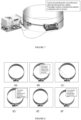
- diamond wire cutter 100 comprises diamond wire saw 1, movable pulley cart 10 disposed proximate, or otherwise coupled or docked, to diamond wire saw 1, and chain tensioner 32 ( Fig. 2 ) adapted to receive a predetermined portion of chain 30 and maintain tension on chain 30.
- diamond wire saw 1 may comprise docking lugs 56 ( Fig. 3 ) and movable pulley cart 10 comprise a complimentary set of lug receivers 16 ( Fig. 3 ).
- diamond wire saw 1 may comprise a set of docking lugs 56 on each of two opposing sides and movable pulley cart 10 comprise a complimentary set of lug receivers 16 on each of its two opposing sides to allowing docking of movable pulley cart 10 at either end of diamond wire saw 1.
- diamond wire saw 1 comprises diamond wire rotator 40; diamond wire 50, comprising a fixed total length and a variable exposed length and operatively in communication with diamond wire rotator 40; chain 30, comprising first chain end 30a ( Fig. 3 ) and second chain end 30b ( Fig. 3 ); and chain driver 31 operatively connected to chain 30.
- diamond wire cutter 100 comprises housing 55 in which at least some components of diamond wire saw 1 are at least partially housed.
- Chain driver 31 typically comprises a motor and a drive wheel operatively connected to the motor.
- Chain tensioner 32 is typically present as well and may be disposed at least partially within diamond wire saw 1.
- diamond wire saw 1 further comprises one or more expandable pulleys 53 adapted to accept diamond wire 50.
- diamond wire saw 1 further comprises one or more buoyancy floats 60 and/or one or more magnets 62 where magnets 62 are adapted to aid in adhering diamond wire saw 1 to a structure to be cut such as pipe 200 ( Fig. 4 ).
- diamond wire cutter 100 typically comprises one or more, usually two, remotely operated vehicle compatible handles 13 disposed about a predetermined portion of 1 diamond wire saw 1, e.g. on opposing sides of housing 55, as well as remotely operated vehicle power interface 54 which is operatively in communication with diamond wire rotator 40 and/or chain driver 31. Because various components of diamond wire cutter 100 can be hydraulically and/or electrically operated, remotely operated vehicle power interface 54 can be a hydraulic power interface, an electrical power interface, or the like, or a combination thereof.
- movable pulley cart 10 is typically operatively connected to chain 30 such as at chain receiver 14 which adapted to receive first chain end 30a and/or second chain end 30b.
- chain receiver 14 may be a single connection point, as illustrated in Fig. 3 , or two separate chain receivers, first chain receiver 14a and second chain receiver 14b (neither shown in the illustrations) which can be located at two separate places of movable pulley cart 10.
- movable pulley cart 10 is releasably connected to diamond wire saw 1, by way of example and not limitation such as being selectively dockable to diamond wire saw 1.
- Movable pulley cart 10 typically comprises one or more diamond wire pulleys 13 adapted to receive a portion of diamond wire 50.
- diamond wire saw 1 is a wire carrier which comprises a wire carrier housing similar to housing 55, a wire carrier chain similar to chain 30, and a diamond wire similar to diamond wire 50.
- movable pulley cart 10 is releasably connected to the wire carrier housing such as by being selectively dockable to the wire carrier housing, operatively connected to the wire carrier chain, and adapted to receive a portion of the diamond wire.
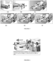
- FIG. 4 through-cutting of a tubular, e.g. pipe 200 ( Fig. 4 ), may be accomplished using diamond wire cutter 100 ( Fig. 4 ), which is as described above.
- diamond wire cutter 100 Fig. 4
- ROV remotely operated vehicle
- FIG. 4 Use of diamond wire cutter 100 typically also only requires one ROV 300 to install and operate, e.g. there are no cranes required.
- Chain 30 is then disposed about a predetermined portion of an outer surface of tubular 200, e.g. about an entire circumference of tubular 200, such as by using ROV 300 and first chain end 30a ( Fig. 3 ) and second chain end 30b ( Fig. 3 ) secured or otherwise attached to movable pulley cart 10 ( Fig. 3 ).
- movable pulley cart 10 may be engaged against tubular 200 by fitting chain 30 in chain tensioner 32 ( Fig. 2 ) and tensioning chain 30 about tubular 200 until a desired tension is achieved.
- Movable pulley cart 10 may be started from a position wherein movable pulley cart 10 is initially removably parked on or otherwise attached or docked to diamond wire saw 1. Movable pulley cart 10 is released from diamond wire saw 1 prior to moving movable pulley cart 10 about the predetermined portion of the outer surface of tubular 200. Where diamond wire saw 1 comprises one or more magnets 62, these magnets 62 may be used to aid in adhering diamond wire saw 1 to tubular 200.
- movable pulley cart 10 Once movable pulley cart 10 is engaged against tubular 200, rotation of diamond wire 50 may begin. As diamond wire 50 rotates, movable pulley cart 10 is moved about the predetermined portion of the outer surface of tubular 200. As illustrated at Figs. 8A-8E , in embodiments diamond wire 50 may be extended towards tubular 200 from diamond wire saw 1 to engage tubular 200, e.g. as movable pulley cart 10 travels about the outer surface of tubular 200. While movable pulley cart 10 travels about the outer surface of tubular 200, an exposed length of diamond wire 50 may be allowed to either lengthen or shorten as needed to allow diamond wire 50 to engage the outer surface of tubular 200, thereby cutting tubular 200.
- the lengthening/shortening can be accomplished at least in part by contracting or extending chain tensioner 32 and/or by contracting or extending diamond wire 50 with respect to diamond wire saw 1 to keep the exposed length of diamond wire 50 in tension while movable pulley cart 10 moves about the predetermined portion of the outer surface of the tubular 200.
- movable pulley cart 10 When cutting is competed, movable pulley cart 10 may be parked back on, or otherwise attached or docked to, diamond wire saw 1, e.g. on a side opposite the side of diamond wire saw from which movable cart 10 was first attached or docked.
- diamond wire cutter 100 using an adjustable length pulley system and movable pulley cart 10, can perform a through-cut of complete sections of tubular 200 by moving movable cart 10 about the outer circumference of tubular 200 while using diamond wire 50 to cut tubular 200 between movable cart 10 and diamond wire saw 1.
Landscapes
- Engineering & Computer Science (AREA)
- Mechanical Engineering (AREA)
- Processing Of Stones Or Stones Resemblance Materials (AREA)
- Finish Polishing, Edge Sharpening, And Grinding By Specific Grinding Devices (AREA)
Claims (15)
- Diamantdrahtschneider (100), umfassend:a. eine Diamantdrahtsäge (1) zum Schneiden einer Struktur (200), umfassend:i. eine Diamantdrahtdreheinrichtung (40);ii. einen Diamantdraht (50), der mit der Diamantdrahtdreheinrichtung zusammenwirkt, wobei der
Diamantdraht eine feste Gesamtlänge und eine variable freie Länge aufweist;iii. eine Kette (30), die ein erstes Kettenende (30a) und ein zweites Kettenende (30b) umfasst, wobei die Kette um einen vorgegebenen Teil einer Außenfläche der zu schneidenden Struktur (200) gelegt werden kann; undiv. einen Kettenantrieb (31), der mit der Kette zusammenwirkt;b. einen beweglichen Seilscheibenwagen (10), der sich um den vorgegebenen Teil der Außenfläche der Struktur (200) herum bewegen lässt und in der Nähe der Diamantdrahtsäge angeordnet ist, wobei der bewegliche Seilscheibenwagen folgendes umfasst:i. eine Diamantdrahtseilscheibe (13), die dazu ausgelegt ist, einen Teil des Diamantdrahts aufzunehmen; undii. eine Kettenaufnahme (14), die dazu ausgelegt ist, das erste Kettenende (30a) und das zweite Kettenende (30b) aufzunehmen, wobei die Kettenaufnahme mit der Kette (30) zusammenwirkt; undc. einen Kettenspanner (32), der dazu ausgelegt ist, einen vorgegebenen Teil der Kette aufzunehmen und die Spannung der Kette aufrecht zu erhalten. - Diamantdrahtschneider nach Anspruch 1,
bei welchem der Kettenspanner (32) wenigstens teilweise innerhalb der Diamantdrahtsäge (1) angeordnet ist. - Diamantdrahtschneider nach Anspruch 1,
bei welchem der bewegliche Seilscheibenwagen (10), welcher in der Nähe der Diamantdrahtsäge (1) angeordnet ist, lösbar mit der Diamantdrahtsäge verbunden ist. - Diamantdrahtschneider nach Anspruch 1,
bei welchem die Diamantdrahtsäge (1) weiter eine expandierbare Seilscheibe (53) umfasst, die dazu ausgelegt ist, den Diamantdraht aufzunehmen. - Diamantdrahtschneider nach Anspruch 1,
bei welchem die Diamantdrahtsäge (1) weiter einen Schwimmkörper (60) umfasst. - Diamantdrahtschneider nach Anspruch 1,
bei welchem die Diamantdrahtsäge (1) weiter einen Magneten (62) umfasst, der dazu ausgelegt ist, die Diamantdrahtsäge beim Anhaften an einer zu schneidenden Struktur (200) zu unterstützen. - Diamantdrahtschneider nach Anspruch 1,
bei welchem der Diamantdrahtschneider (100) einen mit einem fernbedienbaren Fahrzeug kompatiblen Diamantdrahtschneider umfasst, wobei der mit einem fernbedienbaren Fahrzeug kompatible Diamantdrahtschneider folgendes umfasst:a. einen mit einem fernbedienbaren Fahrzeug kompatiblen Handgriff (13), der an einem vorgegebenen Teil der Diamantdrahtsäge (1) angeordnet ist; undb. eine Energieversorgungsschnittstelle (54) für ein fernbedienbares Fahrzeug, welche in Wirkverbindung mit der Diamantdrahtdreheinrichtung und dem Kettenantrieb steht. - Diamantdrahtschneider nach Anspruch 1,
bei welchem der Kettenantrieb (31) folgendes umfasst:a. einen Motor; undb. ein Antriebsrad, welches mit dem Motor in Wirkverbindung steht. - Diamantdrahtschneider nach Anspruch 1,
bei welchem die Kettenaufnahme (14) folgendes umfasst:a. eine erste Kettenaufnahme (14a), die dazu ausgelegt ist, das erste Kettenende (30a) aufzunehmen; undb. eine zweite Kettenaufnahme (14b), die dazu ausgelegt ist, das zweite Kettenende (30b) aufzunehmen. - Verfahren zum Durchschneiden einer Struktur (200), bei welchem ein Diamantdrahtschneider verwendet wird, wobei der Diamantdrahtschneider umfasst:eine Diamantdrahtsäge, umfassend: eine Diamantdrahtdreheinrichtung, einen Diamantdraht, der mit der Diamantdrahtdreheinrichtung zusammenwirkt und eine feste Gesamtlänge und eine variable freie Länge aufweist, undeine Kette, die ein erstes Kettenende und ein zweites Kettenende umfasst, undeinen Kettenantrieb, der mit der Kette in Wirkverbindung steht;einen beweglichen Seilscheibenwagen, der in der Nähe der Diamantdrahtsäge angeordnet ist, der mit der Kette in Wirkverbindung steht und eineDiamantdrahtseilscheibe umfasst, die dazu ausgelegt ist, einen Teil des Diamantdrahts aufzunehmen; sowie einen Kettenspanner, der dazu ausgelegt ist, einen vorgegebenen Teil der Kette aufzunehmen und die Spannung der Kette aufrecht zu erhalten, wobei das Verfahren folgendes umfasst:a. Anordnung der Kette (30) um einen vorgegebenen Teil einer Außenfläche der Struktur (200) herum;b. Befestigen des ersten Kettenendes (30a) und des zweiten Kettenendes (30b) an dem beweglichen Seilscheibenwagen (10);c. in Eingriff bringen des beweglichen Seilscheibenwagens mit der Struktur (200) durch Spannen der Kette um die Struktur (200) herum;d. Drehen des Diamantdrahts (50);e. Bewegen des beweglichen Seilscheibenwagens um den vorgegebenen Teil der Außenfläche der Struktur (200) herum, während einer freien Länge des Diamantdrahts ermöglicht wird, sich nach Bedarf zu verlängern oder zu verkürzen, um die Außenfläche der Struktur (200) zu umgreifen, während der Diamantdraht gedreht wird, um die Struktur (200) zu schneiden; undf. Zusammenziehen oder Entspannen des Kettenspanners, um die freiliegende Länge des Diamantdrahts unter Spannung zu halten, während der bewegbare Seilscheibenwagen sich um den vorgegebenen Teil der Außenfläche der Struktur (200) herum bewegt.
- Verfahren nach Anspruch 10, weiter umfassend:a. Starten des beweglichen Seilscheibenwagens von einer Position, an welcher der bewegliche Seilscheibenwagen zu Anfang lösbar an der Diamantdrahtsäge befestigt ist;b. Lösen des beweglichen Seilscheibenwagens von der Diamantdrahtsäge, bevor der bewegliche Seilscheibenwagen um den vorgegebenen Teil der Außenfläche der Struktur (200) herum bewegt wird; undc. wenn das Schneiden beendet ist, wieder Fixieren des beweglichen Seilscheibenwagens an der Diamantdrahtsäge.
- Verfahren nach Anspruch 10,
bei welchem die Diamantdrahtsäge weiter einen Magneten umfasst, wobei das Verfahren weiter umfasst, dass der Magnet eingesetzt wird, um das Anhaften der Diamantdrahtsäge an der Struktur (200) zu unterstützen. - Verfahren nach Anspruch 10,
welches weiter die Verwendung eines fernbedienbaren Fahrzeugs (ROV) umfasst, um den Diamantdrahtschneider (100) zu einer Position zu bewegen, die der Struktur (200) nahegelegen ist, bevor der bewegbar Seilscheibenwagen um den vorgegebenen Teil der Außenfläche der Struktur (200) herum bewegt wird. - Verfahren Anspruch 10,
bei welchem die Struktur (200) eine Röhre umfasst. - Diamantdrahtschneider nach Anspruch 1,
bei welchem die Struktur (200) eine Röhre umfasst.
Applications Claiming Priority (2)
| Application Number | Priority Date | Filing Date | Title |
|---|---|---|---|
| US201662395268P | 2016-09-15 | 2016-09-15 | |
| PCT/US2017/051770 WO2018053259A1 (en) | 2016-09-15 | 2017-09-15 | Chain driven diamond wire cutter |
Publications (4)
| Publication Number | Publication Date |
|---|---|
| EP3512674A1 EP3512674A1 (de) | 2019-07-24 |
| EP3512674A4 EP3512674A4 (de) | 2020-05-06 |
| EP3512674B1 true EP3512674B1 (de) | 2023-09-13 |
| EP3512674C0 EP3512674C0 (de) | 2023-09-13 |
Family
ID=61559016
Family Applications (1)
| Application Number | Title | Priority Date | Filing Date |
|---|---|---|---|
| EP17851598.7A Active EP3512674B1 (de) | 2016-09-15 | 2017-09-15 | Kettengetriebener diamantdrahtschneider |
Country Status (3)
| Country | Link |
|---|---|
| US (1) | US10322460B2 (de) |
| EP (1) | EP3512674B1 (de) |
| WO (1) | WO2018053259A1 (de) |
Families Citing this family (1)
| Publication number | Priority date | Publication date | Assignee | Title |
|---|---|---|---|---|
| CN110421728B (zh) * | 2019-08-16 | 2021-08-03 | 南京溧水高新产业股权投资有限公司 | 一种用于大理石等距离安全切割的切割装置 |
Family Cites Families (8)
| Publication number | Priority date | Publication date | Assignee | Title |
|---|---|---|---|---|
| ITGE20030011A1 (it) * | 2003-02-12 | 2004-08-13 | Francesco Matteucci | Metodo per il taglio e la rimozione |
| US7406905B2 (en) * | 2006-07-28 | 2008-08-05 | Oceaneering International, Inc | System for driving a wire loop cutting element |
| US8056633B2 (en) * | 2008-04-28 | 2011-11-15 | Barra Marc T | Apparatus and method for removing subsea structures |
| US7922424B2 (en) * | 2008-06-20 | 2011-04-12 | Tetra Technologies, Inc. | Method of cutting target members using a cutting saw device |
| US8833219B2 (en) * | 2009-01-26 | 2014-09-16 | Illinois Tool Works Inc. | Wire saw |
| US20140157964A1 (en) * | 2012-12-12 | 2014-06-12 | Oceaneering International, Inc. | Underwater Wire Saw And Method Of Use |
| US9636761B2 (en) * | 2013-07-25 | 2017-05-02 | MacTech, Inc. | Modular cutting system, method and apparatus |
| WO2017007946A1 (en) * | 2015-07-07 | 2017-01-12 | Mimouni Nabil | Pile removal system |
-
2017
- 2017-09-15 EP EP17851598.7A patent/EP3512674B1/de active Active
- 2017-09-15 WO PCT/US2017/051770 patent/WO2018053259A1/en not_active Ceased
- 2017-09-15 US US15/705,760 patent/US10322460B2/en active Active
Also Published As
| Publication number | Publication date |
|---|---|
| EP3512674A4 (de) | 2020-05-06 |
| WO2018053259A1 (en) | 2018-03-22 |
| US10322460B2 (en) | 2019-06-18 |
| US20180071844A1 (en) | 2018-03-15 |
| EP3512674A1 (de) | 2019-07-24 |
| EP3512674C0 (de) | 2023-09-13 |
Similar Documents
| Publication | Publication Date | Title |
|---|---|---|
| CA2659200A1 (en) | System for driving a wire loop cutting element | |
| US8286625B2 (en) | Underwater diamond wire saw assembly | |
| US20190276993A1 (en) | Trenching Assembly | |
| EP3512674B1 (de) | Kettengetriebener diamantdrahtschneider | |
| JP2008125340A (ja) | ケーブル撤去装置 | |
| FR2967598A3 (fr) | Dispositif de percage pour un outil oscillant | |
| US20080304915A1 (en) | Method and Device For Attaching a Subsea Cutting Apparatus | |
| WO2008131772A2 (en) | Drilling system with a barrel drilling head driven by a downhole tractor | |
| JP2019103432A (ja) | 伐採装置 | |
| CN108967115B (zh) | 一种组合式挖树方法及挖树机 | |
| KR101442185B1 (ko) | 작업도구 연결용 회전식 커넥터 | |
| KR101886962B1 (ko) | 상,하수관로 연결관 및 슬러지 제거용 커팅장치 | |
| EP1794414B1 (de) | Antrieb für eine schneide- oder schleifmaschine | |
| KR101358337B1 (ko) | 파이프라인용 펌프 설치장치와 이를 구비한 선박 및 이를 이용한 펌프 설치방법 | |
| JPH06212663A (ja) | ミーリングドラムの助けをかりて地中に溝を堀る装置 | |
| JP4739939B2 (ja) | 電柱切断機 | |
| JP6608009B1 (ja) | 海底ケーブルの埋設方法 | |
| JP6426342B2 (ja) | 水中コアドリル工法及びシステム | |
| EP2236260A1 (de) | Steinschneidemaschine | |
| CN205817523U (zh) | 高压玻璃钢管道手动、电动一体磨锥机 | |
| EP1840322B1 (de) | Drehschlagbohrvorrichtung und Verfahren | |
| CH647705A5 (fr) | Dispositif de relevage d'outil de percage pour perceuse electrique a main. | |
| KR20230174979A (ko) | 관체 천공장치 | |
| CN109937833B (zh) | 橡胶树干自动开沟机 | |
| CN108188905B (zh) | 一种手持式半自动管材切割装置及管材切割方法 |
Legal Events
| Date | Code | Title | Description |
|---|---|---|---|
| STAA | Information on the status of an ep patent application or granted ep patent |
Free format text: STATUS: THE INTERNATIONAL PUBLICATION HAS BEEN MADE |
|
| PUAI | Public reference made under article 153(3) epc to a published international application that has entered the european phase |
Free format text: ORIGINAL CODE: 0009012 |
|
| STAA | Information on the status of an ep patent application or granted ep patent |
Free format text: STATUS: REQUEST FOR EXAMINATION WAS MADE |
|
| 17P | Request for examination filed |
Effective date: 20190215 |
|
| AK | Designated contracting states |
Kind code of ref document: A1 Designated state(s): AL AT BE BG CH CY CZ DE DK EE ES FI FR GB GR HR HU IE IS IT LI LT LU LV MC MK MT NL NO PL PT RO RS SE SI SK SM TR |
|
| AX | Request for extension of the european patent |
Extension state: BA ME |
|
| DAV | Request for validation of the european patent (deleted) | ||
| DAX | Request for extension of the european patent (deleted) | ||
| A4 | Supplementary search report drawn up and despatched |
Effective date: 20200403 |
|
| RIC1 | Information provided on ipc code assigned before grant |
Ipc: B26D 1/547 20060101AFI20200330BHEP Ipc: B26D 7/02 20060101ALI20200330BHEP Ipc: B23D 57/00 20060101ALI20200330BHEP |
|
| GRAP | Despatch of communication of intention to grant a patent |
Free format text: ORIGINAL CODE: EPIDOSNIGR1 |
|
| STAA | Information on the status of an ep patent application or granted ep patent |
Free format text: STATUS: GRANT OF PATENT IS INTENDED |
|
| INTG | Intention to grant announced |
Effective date: 20211217 |
|
| GRAJ | Information related to disapproval of communication of intention to grant by the applicant or resumption of examination proceedings by the epo deleted |
Free format text: ORIGINAL CODE: EPIDOSDIGR1 |
|
| STAA | Information on the status of an ep patent application or granted ep patent |
Free format text: STATUS: REQUEST FOR EXAMINATION WAS MADE |
|
| INTC | Intention to grant announced (deleted) | ||
| GRAP | Despatch of communication of intention to grant a patent |
Free format text: ORIGINAL CODE: EPIDOSNIGR1 |
|
| STAA | Information on the status of an ep patent application or granted ep patent |
Free format text: STATUS: GRANT OF PATENT IS INTENDED |
|
| INTG | Intention to grant announced |
Effective date: 20220523 |
|
| GRAJ | Information related to disapproval of communication of intention to grant by the applicant or resumption of examination proceedings by the epo deleted |
Free format text: ORIGINAL CODE: EPIDOSDIGR1 |
|
| STAA | Information on the status of an ep patent application or granted ep patent |
Free format text: STATUS: REQUEST FOR EXAMINATION WAS MADE |
|
| RAP1 | Party data changed (applicant data changed or rights of an application transferred) |
Owner name: CLAXTON ENGINEERING SERVICES AS |
|
| INTC | Intention to grant announced (deleted) | ||
| GRAP | Despatch of communication of intention to grant a patent |
Free format text: ORIGINAL CODE: EPIDOSNIGR1 |
|
| STAA | Information on the status of an ep patent application or granted ep patent |
Free format text: STATUS: GRANT OF PATENT IS INTENDED |
|
| INTG | Intention to grant announced |
Effective date: 20221130 |
|
| GRAJ | Information related to disapproval of communication of intention to grant by the applicant or resumption of examination proceedings by the epo deleted |
Free format text: ORIGINAL CODE: EPIDOSDIGR1 |
|
| STAA | Information on the status of an ep patent application or granted ep patent |
Free format text: STATUS: REQUEST FOR EXAMINATION WAS MADE |
|
| GRAP | Despatch of communication of intention to grant a patent |
Free format text: ORIGINAL CODE: EPIDOSNIGR1 |
|
| STAA | Information on the status of an ep patent application or granted ep patent |
Free format text: STATUS: GRANT OF PATENT IS INTENDED |
|
| INTC | Intention to grant announced (deleted) | ||
| INTG | Intention to grant announced |
Effective date: 20230405 |
|
| P01 | Opt-out of the competence of the unified patent court (upc) registered |
Effective date: 20230526 |
|
| GRAS | Grant fee paid |
Free format text: ORIGINAL CODE: EPIDOSNIGR3 |
|
| GRAA | (expected) grant |
Free format text: ORIGINAL CODE: 0009210 |
|
| STAA | Information on the status of an ep patent application or granted ep patent |
Free format text: STATUS: THE PATENT HAS BEEN GRANTED |
|
| AK | Designated contracting states |
Kind code of ref document: B1 Designated state(s): AL AT BE BG CH CY CZ DE DK EE ES FI FR GB GR HR HU IE IS IT LI LT LU LV MC MK MT NL NO PL PT RO RS SE SI SK SM TR |
|
| REG | Reference to a national code |
Ref country code: GB Ref legal event code: FG4D |
|
| REG | Reference to a national code |
Ref country code: CH Ref legal event code: EP |
|
| REG | Reference to a national code |
Ref country code: DE Ref legal event code: R096 Ref document number: 602017074259 Country of ref document: DE |
|
| REG | Reference to a national code |
Ref country code: IE Ref legal event code: FG4D |
|
| U01 | Request for unitary effect filed |
Effective date: 20231004 |
|
| P04 | Withdrawal of opt-out of the competence of the unified patent court (upc) registered |
Effective date: 20231010 |
|
| U07 | Unitary effect registered |
Designated state(s): AT BE BG DE DK EE FI FR IT LT LU LV MT NL PT SE SI Effective date: 20231013 |
|
| REG | Reference to a national code |
Ref country code: NO Ref legal event code: T2 Effective date: 20230913 |
|
| PG25 | Lapsed in a contracting state [announced via postgrant information from national office to epo] |
Ref country code: GR Free format text: LAPSE BECAUSE OF FAILURE TO SUBMIT A TRANSLATION OF THE DESCRIPTION OR TO PAY THE FEE WITHIN THE PRESCRIBED TIME-LIMIT Effective date: 20231214 |
|
| U20 | Renewal fee for the european patent with unitary effect paid |
Year of fee payment: 7 Effective date: 20231220 |
|
| PG25 | Lapsed in a contracting state [announced via postgrant information from national office to epo] |
Ref country code: RS Free format text: LAPSE BECAUSE OF FAILURE TO SUBMIT A TRANSLATION OF THE DESCRIPTION OR TO PAY THE FEE WITHIN THE PRESCRIBED TIME-LIMIT Effective date: 20230913 Ref country code: HR Free format text: LAPSE BECAUSE OF FAILURE TO SUBMIT A TRANSLATION OF THE DESCRIPTION OR TO PAY THE FEE WITHIN THE PRESCRIBED TIME-LIMIT Effective date: 20230913 Ref country code: GR Free format text: LAPSE BECAUSE OF FAILURE TO SUBMIT A TRANSLATION OF THE DESCRIPTION OR TO PAY THE FEE WITHIN THE PRESCRIBED TIME-LIMIT Effective date: 20231214 |
|
| PG25 | Lapsed in a contracting state [announced via postgrant information from national office to epo] |
Ref country code: IS Free format text: LAPSE BECAUSE OF FAILURE TO SUBMIT A TRANSLATION OF THE DESCRIPTION OR TO PAY THE FEE WITHIN THE PRESCRIBED TIME-LIMIT Effective date: 20240113 |
|
| PG25 | Lapsed in a contracting state [announced via postgrant information from national office to epo] |
Ref country code: ES Free format text: LAPSE BECAUSE OF FAILURE TO SUBMIT A TRANSLATION OF THE DESCRIPTION OR TO PAY THE FEE WITHIN THE PRESCRIBED TIME-LIMIT Effective date: 20230913 |
|
| PG25 | Lapsed in a contracting state [announced via postgrant information from national office to epo] |
Ref country code: SM Free format text: LAPSE BECAUSE OF FAILURE TO SUBMIT A TRANSLATION OF THE DESCRIPTION OR TO PAY THE FEE WITHIN THE PRESCRIBED TIME-LIMIT Effective date: 20230913 Ref country code: RO Free format text: LAPSE BECAUSE OF FAILURE TO SUBMIT A TRANSLATION OF THE DESCRIPTION OR TO PAY THE FEE WITHIN THE PRESCRIBED TIME-LIMIT Effective date: 20230913 Ref country code: IS Free format text: LAPSE BECAUSE OF FAILURE TO SUBMIT A TRANSLATION OF THE DESCRIPTION OR TO PAY THE FEE WITHIN THE PRESCRIBED TIME-LIMIT Effective date: 20240113 Ref country code: ES Free format text: LAPSE BECAUSE OF FAILURE TO SUBMIT A TRANSLATION OF THE DESCRIPTION OR TO PAY THE FEE WITHIN THE PRESCRIBED TIME-LIMIT Effective date: 20230913 Ref country code: CZ Free format text: LAPSE BECAUSE OF FAILURE TO SUBMIT A TRANSLATION OF THE DESCRIPTION OR TO PAY THE FEE WITHIN THE PRESCRIBED TIME-LIMIT Effective date: 20230913 Ref country code: SK Free format text: LAPSE BECAUSE OF FAILURE TO SUBMIT A TRANSLATION OF THE DESCRIPTION OR TO PAY THE FEE WITHIN THE PRESCRIBED TIME-LIMIT Effective date: 20230913 |
|
| REG | Reference to a national code |
Ref country code: CH Ref legal event code: PL |
|
| PG25 | Lapsed in a contracting state [announced via postgrant information from national office to epo] |
Ref country code: PL Free format text: LAPSE BECAUSE OF FAILURE TO SUBMIT A TRANSLATION OF THE DESCRIPTION OR TO PAY THE FEE WITHIN THE PRESCRIBED TIME-LIMIT Effective date: 20230913 |
|
| REG | Reference to a national code |
Ref country code: DE Ref legal event code: R097 Ref document number: 602017074259 Country of ref document: DE |
|
| PG25 | Lapsed in a contracting state [announced via postgrant information from national office to epo] |
Ref country code: MC Free format text: LAPSE BECAUSE OF FAILURE TO SUBMIT A TRANSLATION OF THE DESCRIPTION OR TO PAY THE FEE WITHIN THE PRESCRIBED TIME-LIMIT Effective date: 20230913 |
|
| REG | Reference to a national code |
Ref country code: IE Ref legal event code: MM4A |
|
| PG25 | Lapsed in a contracting state [announced via postgrant information from national office to epo] |
Ref country code: IE Free format text: LAPSE BECAUSE OF NON-PAYMENT OF DUE FEES Effective date: 20230915 |
|
| PG25 | Lapsed in a contracting state [announced via postgrant information from national office to epo] |
Ref country code: CH Free format text: LAPSE BECAUSE OF NON-PAYMENT OF DUE FEES Effective date: 20230930 |
|
| PLBE | No opposition filed within time limit |
Free format text: ORIGINAL CODE: 0009261 |
|
| STAA | Information on the status of an ep patent application or granted ep patent |
Free format text: STATUS: NO OPPOSITION FILED WITHIN TIME LIMIT |
|
| PG25 | Lapsed in a contracting state [announced via postgrant information from national office to epo] |
Ref country code: MC Free format text: LAPSE BECAUSE OF FAILURE TO SUBMIT A TRANSLATION OF THE DESCRIPTION OR TO PAY THE FEE WITHIN THE PRESCRIBED TIME-LIMIT Effective date: 20230913 Ref country code: IE Free format text: LAPSE BECAUSE OF NON-PAYMENT OF DUE FEES Effective date: 20230915 Ref country code: CH Free format text: LAPSE BECAUSE OF NON-PAYMENT OF DUE FEES Effective date: 20230930 |
|
| 26N | No opposition filed |
Effective date: 20240614 |
|
| U20 | Renewal fee for the european patent with unitary effect paid |
Year of fee payment: 8 Effective date: 20240904 |
|
| P05 | Withdrawal of opt-out of the competence of the unified patent court (upc) changed |
Free format text: CASE NUMBER: APP_579466/2023 Effective date: 20231013 |
|
| PG25 | Lapsed in a contracting state [announced via postgrant information from national office to epo] |
Ref country code: CY Free format text: LAPSE BECAUSE OF FAILURE TO SUBMIT A TRANSLATION OF THE DESCRIPTION OR TO PAY THE FEE WITHIN THE PRESCRIBED TIME-LIMIT; INVALID AB INITIO Effective date: 20170915 |
|
| PG25 | Lapsed in a contracting state [announced via postgrant information from national office to epo] |
Ref country code: HU Free format text: LAPSE BECAUSE OF FAILURE TO SUBMIT A TRANSLATION OF THE DESCRIPTION OR TO PAY THE FEE WITHIN THE PRESCRIBED TIME-LIMIT; INVALID AB INITIO Effective date: 20170915 |
|
| PGFP | Annual fee paid to national office [announced via postgrant information from national office to epo] |
Ref country code: NO Payment date: 20250923 Year of fee payment: 9 |
|
| PGFP | Annual fee paid to national office [announced via postgrant information from national office to epo] |
Ref country code: GB Payment date: 20250919 Year of fee payment: 9 |
|
| U20 | Renewal fee for the european patent with unitary effect paid |
Year of fee payment: 9 Effective date: 20250919 |
|
| PG25 | Lapsed in a contracting state [announced via postgrant information from national office to epo] |
Ref country code: TR Free format text: LAPSE BECAUSE OF FAILURE TO SUBMIT A TRANSLATION OF THE DESCRIPTION OR TO PAY THE FEE WITHIN THE PRESCRIBED TIME-LIMIT Effective date: 20230913 |