EP3512674B1 - Chain driven diamond wire cutter - Google Patents
Chain driven diamond wire cutter Download PDFInfo
- Publication number
- EP3512674B1 EP3512674B1 EP17851598.7A EP17851598A EP3512674B1 EP 3512674 B1 EP3512674 B1 EP 3512674B1 EP 17851598 A EP17851598 A EP 17851598A EP 3512674 B1 EP3512674 B1 EP 3512674B1
- Authority
- EP
- European Patent Office
- Prior art keywords
- diamond wire
- chain
- movable pulley
- cutter
- wire saw
- Prior art date
- Legal status (The legal status is an assumption and is not a legal conclusion. Google has not performed a legal analysis and makes no representation as to the accuracy of the status listed.)
- Active
Links
- 229910003460 diamond Inorganic materials 0.000 title claims description 115
- 239000010432 diamond Substances 0.000 title claims description 115
- 238000005520 cutting process Methods 0.000 claims description 16
- 238000000034 method Methods 0.000 claims description 9
- 238000004891 communication Methods 0.000 claims description 5
- 238000005516 engineering process Methods 0.000 description 3
- 238000003032 molecular docking Methods 0.000 description 3
- 238000005553 drilling Methods 0.000 description 2
- 238000009412 basement excavation Methods 0.000 description 1
- 238000010276 construction Methods 0.000 description 1
- 239000000463 material Substances 0.000 description 1
- 238000004904 shortening Methods 0.000 description 1
Images


Classifications
-
- B—PERFORMING OPERATIONS; TRANSPORTING
- B23—MACHINE TOOLS; METAL-WORKING NOT OTHERWISE PROVIDED FOR
- B23D—PLANING; SLOTTING; SHEARING; BROACHING; SAWING; FILING; SCRAPING; LIKE OPERATIONS FOR WORKING METAL BY REMOVING MATERIAL, NOT OTHERWISE PROVIDED FOR
- B23D57/00—Sawing machines or sawing devices not covered by one of the preceding groups B23D45/00 - B23D55/00
- B23D57/003—Sawing machines or sawing devices working with saw wires, characterised only by constructional features of particular parts
- B23D57/0061—Sawing machines or sawing devices working with saw wires, characterised only by constructional features of particular parts of devices for guiding or feeding saw wires
-
- B—PERFORMING OPERATIONS; TRANSPORTING
- B23—MACHINE TOOLS; METAL-WORKING NOT OTHERWISE PROVIDED FOR
- B23D—PLANING; SLOTTING; SHEARING; BROACHING; SAWING; FILING; SCRAPING; LIKE OPERATIONS FOR WORKING METAL BY REMOVING MATERIAL, NOT OTHERWISE PROVIDED FOR
- B23D57/00—Sawing machines or sawing devices not covered by one of the preceding groups B23D45/00 - B23D55/00
- B23D57/003—Sawing machines or sawing devices working with saw wires, characterised only by constructional features of particular parts
- B23D57/0053—Sawing machines or sawing devices working with saw wires, characterised only by constructional features of particular parts of drives for saw wires; of wheel mountings; of wheels
-
- B—PERFORMING OPERATIONS; TRANSPORTING
- B23—MACHINE TOOLS; METAL-WORKING NOT OTHERWISE PROVIDED FOR
- B23D—PLANING; SLOTTING; SHEARING; BROACHING; SAWING; FILING; SCRAPING; LIKE OPERATIONS FOR WORKING METAL BY REMOVING MATERIAL, NOT OTHERWISE PROVIDED FOR
- B23D57/00—Sawing machines or sawing devices not covered by one of the preceding groups B23D45/00 - B23D55/00
- B23D57/003—Sawing machines or sawing devices working with saw wires, characterised only by constructional features of particular parts
- B23D57/0069—Sawing machines or sawing devices working with saw wires, characterised only by constructional features of particular parts of devices for tensioning saw wires
-
- B—PERFORMING OPERATIONS; TRANSPORTING
- B23—MACHINE TOOLS; METAL-WORKING NOT OTHERWISE PROVIDED FOR
- B23D—PLANING; SLOTTING; SHEARING; BROACHING; SAWING; FILING; SCRAPING; LIKE OPERATIONS FOR WORKING METAL BY REMOVING MATERIAL, NOT OTHERWISE PROVIDED FOR
- B23D57/00—Sawing machines or sawing devices not covered by one of the preceding groups B23D45/00 - B23D55/00
- B23D57/0084—Sawing machines or sawing devices not covered by one of the preceding groups B23D45/00 - B23D55/00 specially adapted for sawing under water or at places accessible with difficulty
-
- B—PERFORMING OPERATIONS; TRANSPORTING
- B23—MACHINE TOOLS; METAL-WORKING NOT OTHERWISE PROVIDED FOR
- B23D—PLANING; SLOTTING; SHEARING; BROACHING; SAWING; FILING; SCRAPING; LIKE OPERATIONS FOR WORKING METAL BY REMOVING MATERIAL, NOT OTHERWISE PROVIDED FOR
- B23D61/00—Tools for sawing machines or sawing devices; Clamping devices for these tools
- B23D61/18—Sawing tools of special type, e.g. wire saw strands, saw blades or saw wire equipped with diamonds or other abrasive particles in selected individual positions
- B23D61/185—Saw wires; Saw cables; Twisted saw strips
-
- B—PERFORMING OPERATIONS; TRANSPORTING
- B28—WORKING CEMENT, CLAY, OR STONE
- B28D—WORKING STONE OR STONE-LIKE MATERIALS
- B28D5/00—Fine working of gems, jewels, crystals, e.g. of semiconductor material; apparatus or devices therefor
- B28D5/04—Fine working of gems, jewels, crystals, e.g. of semiconductor material; apparatus or devices therefor by tools other than rotary type, e.g. reciprocating tools
- B28D5/045—Fine working of gems, jewels, crystals, e.g. of semiconductor material; apparatus or devices therefor by tools other than rotary type, e.g. reciprocating tools by cutting with wires or closed-loop blades
Definitions
- cutting is accomplished using a pulley system and guide wheels.
- This technology is mainly used on shore and has the disadvantage that for large sections, the guide wheels will need to be re-positioned and the wire will have to be shortened at regular intervals through the cutting operation.
- cutting is accomplished using a cart with diamond wire mounted on the cart.
- diamond wire mounted on the cart.
- this technology will not allow for cuts on a straight or inverse curvature surface. Further it requires a track, custom built to the diameter of the section to be cut.
- the apparatus includes a shaft module including a cylindrical shaft including a first cavity configured to receive the pile.
- the apparatus also includes a cutting module coupled to the shaft module, the cutting module including a second cavity configured to receive the pile, clamps configured to clamp onto the pile, and a saw configured to cut the pile.
- the apparatus also includes a drilling module coupled to the cutting module, the drilling module including blades to burrow into an earth surface.
- Prior art document US 2009/266552 A1 discloses a diamond wire cutter and a method for removing a subsea structure wherein a housing defining a subsea structure receiving space and having a jetting system attached at or near the bottom of the housing is used to form an excavation around the subsea structure to the desired depth and a frame attached to or mounted in the housing carries a cutter assembly which is movable from a first position on the frame to a second position on the frame, the first position being on one side of the subsea structure, the second position being on the opposite side of the subsea structure.
- diamond wire cutter 100 comprises diamond wire saw 1, movable pulley cart 10 disposed proximate, or otherwise coupled or docked, to diamond wire saw 1, and chain tensioner 32 ( Fig. 2 ) adapted to receive a predetermined portion of chain 30 and maintain tension on chain 30.
- diamond wire saw 1 may comprise docking lugs 56 ( Fig. 3 ) and movable pulley cart 10 comprise a complimentary set of lug receivers 16 ( Fig. 3 ).
- diamond wire saw 1 may comprise a set of docking lugs 56 on each of two opposing sides and movable pulley cart 10 comprise a complimentary set of lug receivers 16 on each of its two opposing sides to allowing docking of movable pulley cart 10 at either end of diamond wire saw 1.
- diamond wire saw 1 comprises diamond wire rotator 40; diamond wire 50, comprising a fixed total length and a variable exposed length and operatively in communication with diamond wire rotator 40; chain 30, comprising first chain end 30a ( Fig. 3 ) and second chain end 30b ( Fig. 3 ); and chain driver 31 operatively connected to chain 30.
- diamond wire cutter 100 comprises housing 55 in which at least some components of diamond wire saw 1 are at least partially housed.
- Chain driver 31 typically comprises a motor and a drive wheel operatively connected to the motor.
- Chain tensioner 32 is typically present as well and may be disposed at least partially within diamond wire saw 1.
- diamond wire saw 1 further comprises one or more expandable pulleys 53 adapted to accept diamond wire 50.
- diamond wire saw 1 further comprises one or more buoyancy floats 60 and/or one or more magnets 62 where magnets 62 are adapted to aid in adhering diamond wire saw 1 to a structure to be cut such as pipe 200 ( Fig. 4 ).
- diamond wire cutter 100 typically comprises one or more, usually two, remotely operated vehicle compatible handles 13 disposed about a predetermined portion of 1 diamond wire saw 1, e.g. on opposing sides of housing 55, as well as remotely operated vehicle power interface 54 which is operatively in communication with diamond wire rotator 40 and/or chain driver 31. Because various components of diamond wire cutter 100 can be hydraulically and/or electrically operated, remotely operated vehicle power interface 54 can be a hydraulic power interface, an electrical power interface, or the like, or a combination thereof.
- movable pulley cart 10 is typically operatively connected to chain 30 such as at chain receiver 14 which adapted to receive first chain end 30a and/or second chain end 30b.
- chain receiver 14 may be a single connection point, as illustrated in Fig. 3 , or two separate chain receivers, first chain receiver 14a and second chain receiver 14b (neither shown in the illustrations) which can be located at two separate places of movable pulley cart 10.
- movable pulley cart 10 is releasably connected to diamond wire saw 1, by way of example and not limitation such as being selectively dockable to diamond wire saw 1.
- Movable pulley cart 10 typically comprises one or more diamond wire pulleys 13 adapted to receive a portion of diamond wire 50.
- diamond wire saw 1 is a wire carrier which comprises a wire carrier housing similar to housing 55, a wire carrier chain similar to chain 30, and a diamond wire similar to diamond wire 50.
- movable pulley cart 10 is releasably connected to the wire carrier housing such as by being selectively dockable to the wire carrier housing, operatively connected to the wire carrier chain, and adapted to receive a portion of the diamond wire.
- FIG. 4 through-cutting of a tubular, e.g. pipe 200 ( Fig. 4 ), may be accomplished using diamond wire cutter 100 ( Fig. 4 ), which is as described above.
- diamond wire cutter 100 Fig. 4
- ROV remotely operated vehicle
- FIG. 4 Use of diamond wire cutter 100 typically also only requires one ROV 300 to install and operate, e.g. there are no cranes required.
- Chain 30 is then disposed about a predetermined portion of an outer surface of tubular 200, e.g. about an entire circumference of tubular 200, such as by using ROV 300 and first chain end 30a ( Fig. 3 ) and second chain end 30b ( Fig. 3 ) secured or otherwise attached to movable pulley cart 10 ( Fig. 3 ).
- movable pulley cart 10 may be engaged against tubular 200 by fitting chain 30 in chain tensioner 32 ( Fig. 2 ) and tensioning chain 30 about tubular 200 until a desired tension is achieved.
- Movable pulley cart 10 may be started from a position wherein movable pulley cart 10 is initially removably parked on or otherwise attached or docked to diamond wire saw 1. Movable pulley cart 10 is released from diamond wire saw 1 prior to moving movable pulley cart 10 about the predetermined portion of the outer surface of tubular 200. Where diamond wire saw 1 comprises one or more magnets 62, these magnets 62 may be used to aid in adhering diamond wire saw 1 to tubular 200.
- movable pulley cart 10 Once movable pulley cart 10 is engaged against tubular 200, rotation of diamond wire 50 may begin. As diamond wire 50 rotates, movable pulley cart 10 is moved about the predetermined portion of the outer surface of tubular 200. As illustrated at Figs. 8A-8E , in embodiments diamond wire 50 may be extended towards tubular 200 from diamond wire saw 1 to engage tubular 200, e.g. as movable pulley cart 10 travels about the outer surface of tubular 200. While movable pulley cart 10 travels about the outer surface of tubular 200, an exposed length of diamond wire 50 may be allowed to either lengthen or shorten as needed to allow diamond wire 50 to engage the outer surface of tubular 200, thereby cutting tubular 200.
- the lengthening/shortening can be accomplished at least in part by contracting or extending chain tensioner 32 and/or by contracting or extending diamond wire 50 with respect to diamond wire saw 1 to keep the exposed length of diamond wire 50 in tension while movable pulley cart 10 moves about the predetermined portion of the outer surface of the tubular 200.
- movable pulley cart 10 When cutting is competed, movable pulley cart 10 may be parked back on, or otherwise attached or docked to, diamond wire saw 1, e.g. on a side opposite the side of diamond wire saw from which movable cart 10 was first attached or docked.
- diamond wire cutter 100 using an adjustable length pulley system and movable pulley cart 10, can perform a through-cut of complete sections of tubular 200 by moving movable cart 10 about the outer circumference of tubular 200 while using diamond wire 50 to cut tubular 200 between movable cart 10 and diamond wire saw 1.
Description
- This application claims priority from and through
United States Application 62/395,268 titled "Chain Driven Diamond Wire Cutter" and filed on September 15, 2016 - Current technology available for cutting, using diamond wire can be categorized into three categories.
- In a first category, cutting is accomplished using a pulley system and guide wheels. This technology is mainly used on shore and has the disadvantage that for large sections, the guide wheels will need to be re-positioned and the wire will have to be shortened at regular intervals through the cutting operation.
- In a second category, cutting is accomplished using diamond wire saws with clamp. These clamp saws are efficient, but has the main disadvantage that they only fit a small range of diameters and that the tool has to be bigger than the diameter you cut, due to the need for clamp.
- In a third category, cutting is accomplished using a cart with diamond wire mounted on the cart. By only mounting the diamond wire on the cart itself, only the circumference can be cut, not the through section. Further this technology will not allow for cuts on a straight or inverse curvature surface. Further it requires a track, custom built to the diameter of the section to be cut.
- One issue that arises with these systems is that they are not easily useful when cutting large size structures (> 4m outer diameter) subsea.
- Prior art document
WO 2017/007946 A1 which is a document pursuant to Article 54(3) EPC discloses an apparatus for cutting a pile. - In some embodiments, the apparatus includes a shaft module including a cylindrical shaft including a first cavity configured to receive the pile. In some embodiments, the apparatus also includes a cutting module coupled to the shaft module, the cutting module including a second cavity configured to receive the pile, clamps configured to clamp onto the pile, and a saw configured to cut the pile. In some embodiments, the apparatus also includes a drilling module coupled to the cutting module, the drilling module including blades to burrow into an earth surface.
- Prior art document
US 2009/266552 A1 discloses a diamond wire cutter and a method for removing a subsea structure wherein a housing defining a subsea structure receiving space and having a jetting system attached at or near the bottom of the housing is used to form an excavation around the subsea structure to the desired depth and a frame attached to or mounted in the housing carries a cutter assembly which is movable from a first position on the frame to a second position on the frame, the first position being on one side of the subsea structure, the second position being on the opposite side of the subsea structure. - The figures supplied herein illustrate various embodiments of the invention.
-
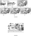
Fig. 1 is a view in partial perspective of an exemplary embodiment of a diamond wire cutter; -
Fig. 2 is a view in partial perspective of the exemplary embodiment of the diamond wire cutter from its opposite side; -
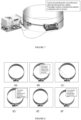
Fig. 3 is a view in partial perspective of a close-up of an end of the exemplary embodiment of the diamond wire cutter; -
Fig. 4 is a view in partial perspective of the exemplary embodiment of the diamond wire cutter deployed about a tubular to be cut; -
Fig. 5 , which includesFigs. 5A-5F , are views in partial perspective of the exemplary embodiment of the diamond wire cutter being initiated; -
Fig. 6 is a view of partial perspective of the exemplary embodiment of the diamond wire cutter about to be engaged; -
Fig. 7 is a view of partial perspective of the exemplary embodiment of the diamond wire cutter beginning to travel about an outer circumference of the tubular to be cut; and -
Fig. 8 is a view of partial perspective of the exemplary embodiment of the diamond wire cutter as it travels about an outer circumference of the tubular to be cut. - Referring now to
Fig. 1 , in an embodimentdiamond wire cutter 100 comprisesdiamond wire saw 1,movable pulley cart 10 disposed proximate, or otherwise coupled or docked, todiamond wire saw 1, and chain tensioner 32 (Fig. 2 ) adapted to receive a predetermined portion ofchain 30 and maintain tension onchain 30. By way of example and not limitation,diamond wire saw 1 may comprise docking lugs 56 (Fig. 3 ) andmovable pulley cart 10 comprise a complimentary set of lug receivers 16 (Fig. 3 ). Although not specifically illustrated,diamond wire saw 1 may comprise a set ofdocking lugs 56 on each of two opposing sides andmovable pulley cart 10 comprise a complimentary set oflug receivers 16 on each of its two opposing sides to allowing docking ofmovable pulley cart 10 at either end of diamond wire saw 1. - In an embodiment,
diamond wire saw 1 comprisesdiamond wire rotator 40;diamond wire 50, comprising a fixed total length and a variable exposed length and operatively in communication withdiamond wire rotator 40;chain 30, comprisingfirst chain end 30a (Fig. 3 ) andsecond chain end 30b (Fig. 3 ); andchain driver 31 operatively connected tochain 30. - In embodiments,
diamond wire cutter 100 comprises housing 55 in which at least some components ofdiamond wire saw 1 are at least partially housed. -
Chain driver 31 typically comprises a motor and a drive wheel operatively connected to the motor. - Chain tensioner 32 is typically present as well and may be disposed at least partially within diamond wire saw 1.
- Referring additionally to
Fig. 2 , in embodiments diamond wire saw 1 further comprises one or moreexpandable pulleys 53 adapted to acceptdiamond wire 50. In addition, in certain embodiments, diamond wire saw 1 further comprises one ormore buoyancy floats 60 and/or one ormore magnets 62 wheremagnets 62 are adapted to aid in adhering diamond wire saw 1 to a structure to be cut such as pipe 200 (Fig. 4 ). - Where it is compatible with a remotely operated vehicle (ROV),
diamond wire cutter 100 typically comprises one or more, usually two, remotely operated vehiclecompatible handles 13 disposed about a predetermined portion of 1diamond wire saw 1, e.g. on opposing sides ofhousing 55, as well as remotely operatedvehicle power interface 54 which is operatively in communication withdiamond wire rotator 40 and/orchain driver 31. Because various components ofdiamond wire cutter 100 can be hydraulically and/or electrically operated, remotely operatedvehicle power interface 54 can be a hydraulic power interface, an electrical power interface, or the like, or a combination thereof. - Referring additionally to
Fig. 3 ,movable pulley cart 10 is typically operatively connected tochain 30 such as atchain receiver 14 which adapted to receivefirst chain end 30a and/orsecond chain end 30b. As one of ordinary skill in these arts will appreciate,chain receiver 14 may be a single connection point, as illustrated inFig. 3 , or two separate chain receivers, first chain receiver 14a and second chain receiver 14b (neither shown in the illustrations) which can be located at two separate places ofmovable pulley cart 10. In most embodiments,movable pulley cart 10 is releasably connected todiamond wire saw 1, by way of example and not limitation such as being selectively dockable todiamond wire saw 1.Movable pulley cart 10 typically comprises one or morediamond wire pulleys 13 adapted to receive a portion ofdiamond wire 50. - In an embodiment,
diamond wire saw 1 is a wire carrier which comprises a wire carrier housing similar tohousing 55, a wire carrier chain similar tochain 30, and a diamond wire similar todiamond wire 50. In these embodiments,movable pulley cart 10 is releasably connected to the wire carrier housing such as by being selectively dockable to the wire carrier housing, operatively connected to the wire carrier chain, and adapted to receive a portion of the diamond wire. - In the operation of an exemplary embodiment, referring generally to
Figs. 4-8 , through-cutting of a tubular, e.g. pipe 200 (Fig. 4 ), may be accomplished using diamond wire cutter 100 (Fig. 4 ), which is as described above. Typically, remotely operated vehicle (ROV) 300 (Fig. 4 ) is used to maneuverdiamond wire cutter 100 to a location proximate tubular 200 to be cut. Use ofdiamond wire cutter 100 typically also only requires oneROV 300 to install and operate, e.g. there are no cranes required. -
Chain 30 is then disposed about a predetermined portion of an outer surface of tubular 200, e.g. about an entire circumference of tubular 200, such as by usingROV 300 andfirst chain end 30a (Fig. 3 ) andsecond chain end 30b (Fig. 3 ) secured or otherwise attached to movable pulley cart 10 (Fig. 3 ). Oncechain 30 is in place,movable pulley cart 10 may be engaged against tubular 200 byfitting chain 30 in chain tensioner 32 (Fig. 2 ) andtensioning chain 30 about tubular 200 until a desired tension is achieved. -
Movable pulley cart 10 may be started from a position whereinmovable pulley cart 10 is initially removably parked on or otherwise attached or docked to diamond wire saw 1.Movable pulley cart 10 is released from diamond wire saw 1 prior to movingmovable pulley cart 10 about the predetermined portion of the outer surface of tubular 200. Where diamond wire saw 1 comprises one ormore magnets 62, thesemagnets 62 may be used to aid in adhering diamond wire saw 1 to tubular 200. - Once
movable pulley cart 10 is engaged against tubular 200, rotation ofdiamond wire 50 may begin. Asdiamond wire 50 rotates,movable pulley cart 10 is moved about the predetermined portion of the outer surface of tubular 200. As illustrated atFigs. 8A-8E , inembodiments diamond wire 50 may be extended towards tubular 200 from diamond wire saw 1 to engage tubular 200, e.g. asmovable pulley cart 10 travels about the outer surface of tubular 200. Whilemovable pulley cart 10 travels about the outer surface of tubular 200, an exposed length ofdiamond wire 50 may be allowed to either lengthen or shorten as needed to allowdiamond wire 50 to engage the outer surface of tubular 200, thereby cutting tubular 200. The lengthening/shortening can be accomplished at least in part by contracting or extending chain tensioner 32 and/or by contracting or extendingdiamond wire 50 with respect to diamond wire saw 1 to keep the exposed length ofdiamond wire 50 in tension whilemovable pulley cart 10 moves about the predetermined portion of the outer surface of the tubular 200. - When cutting is competed,
movable pulley cart 10 may be parked back on, or otherwise attached or docked to, diamond wire saw 1, e.g. on a side opposite the side of diamond wire saw from whichmovable cart 10 was first attached or docked. - Accordingly,
diamond wire cutter 100, using an adjustable length pulley system andmovable pulley cart 10, can perform a through-cut of complete sections of tubular 200 by movingmovable cart 10 about the outer circumference of tubular 200 while usingdiamond wire 50 to cut tubular 200 betweenmovable cart 10 and diamond wire saw 1. - The foregoing disclosure and description of the embodiments are illustrative and explanatory. Various changes in the size, shape, and materials, as well as in the details of the illustrative construction and/or an illustrative method may be made without departing from the the invention as defined by the claims.
Claims (15)
- A diamond wire cutter (100), comprising:a. a diamond wire saw (1) for cutting a structure (200), comprising:i. a diamond wire rotator (40);ii. a diamond wire (50) operatively in communication with the diamond wire rotator, the diamond wire comprising a fixed total length and a variable exposed length;iii. a chain (30) comprising a first chain end (30a) and a second chain end (30b), the chain being disposable about a predetermined portion of an outer surface of the structure (200) to be cut; andiv. a chain driver (31) operatively connected to the chain;b. a movable pulley cart (10) movable about the predetermined portion of the outer surface of the structure (200) and disposed proximate to the diamond wire saw, the movable pulley cart comprising:i. a diamond wire pulley (13) adapted to receive a portion of the diamond wire; andii. a chain receiver (14) adapted to receive the first chain end (30a) and the second chain end (30b) the chain receiver operatively connected to the chain (30); andc. a chain tensioner (32) adapted to receive a predetermined portion of the chain and maintain tension on the chain.
- The diamond wire cutter of Claim 1, wherein the chain tensioner (32) is disposed at least partially within the diamond wire saw (1).
- The diamond wire cutter of Claim 1, wherein the movable pulley cart (10) disposed proximate to the diamond wire saw (1) is releasably connected to the diamond wire saw.
- The diamond wire cutter of Claim 1, wherein the diamond wire saw (1) further comprises an expandable pulley (53) adapted to accept the diamond wire.
- The diamond wire cutter of Claim 1, wherein the diamond wire saw (1) further comprises a buoyancy float (60).
- The diamond wire cutter of Claim 1, wherein the diamond wire saw (1) further comprises a magnet (62) adapted to aid in adhering the diamond wire saw to a structure (200) to be cut.
- The diamond wire cutter of Claim 1, wherein the diamond wire cutter (100) comprises a remotely operated vehicle compatible diamond wire cutter, the remotely operated vehicle compatible diamond wire cutter comprising:a. a remotely operated vehicle compatible handle (13) disposed about a predetermined portion of the diamond wire saw (1); andb. a remotely operated vehicle power interface (54) operatively in communication with the diamond wire rotator and the chain driver.
- The diamond wire cutter of Claim 1, wherein the chain driver (31) comprises:a. a motor; andb. a drive wheel operatively connected to the motor.
- The diamond wire cutter of Claim 1, wherein the chain receiver (14) comprises:a. a first chain receiver (14a) adapted to receive the first chain end (30a); andb. a second chain receiver (14b) adapted to receive the second chain end (30b).
- A method of through-cutting a structure (200) using a diamond wire cutter, the diamond wire cutter comprising a diamond wire saw comprising a diamond wire rotator, a diamond wire operatively in communication with the diamond wire rotator and comprising a fixed total length and a variable exposed length and, a chain comprising a first chain end and a second chain end, and a chain driver operatively connected to the chain; a movable pulley cart disposed proximate to the diamond wire saw, operatively connected to the chain, and comprising a diamond wire pulley adapted to receive a portion of the diamond wire; and a chain tensioner adapted to receive a predetermined portion of the chain and maintain tension on the chain, the method comprising:a. disposing the chain (30) about a predetermined portion of an outer surface of the structure (200);b. securing the first chain end (30a) and the second chain end (30b) to the movable pulley cart (10);c. engaging the movable pulley cart against the structure (200) by tensioning the chain about the structure (200);d. rotating the diamond wire (50);e. moving the movable pulley cart about the predetermined portion of the outer surface of the structure (200) while allowing an exposed length of diamond wire to lengthen or shorten as needed to engage the outer surface of the structure (200) while the diamond wire is being rotated to cut the structure (200); andf. contracting or extending the chain tensioner to keep the exposed length of diamond wire in tension while the movable pulley cart moves about the predetermined portion of the outer surface of the structure (200).
- The method of Claim 10, further comprising:a. starting the movable pulley cart from a position wherein the movable pulley cart is initially removably secured to the diamond wire saw;b. releasing the movable pulley cart from the diamond wire saw prior moving the movable pulley cart about the predetermined portion of the outer surface of the structure (200); andc. when cutting is competed, securing the movable pulley cart back to the diamond wire saw.
- The method of Claim 10, wherein the diamond wire saw further comprises a magnet, the method further comprising using the magnetic to aid in adhering the diamond wire saw to the structure (200).
- The method of Claim 10, further comprising using a remotely operated vehicle (ROV) to maneuver the diamond wire cutter (100) to a location proximate the structure (200) prior to moving movable pulley cart about the predetermined portion of the outer surface of structure (200).
- The method of Claim 10, wherein the structure (200) comprises a tubular.
- The diamond wire cutter of Claim 1, wherein the structure (200) comprises a tubular.
Applications Claiming Priority (2)
| Application Number | Priority Date | Filing Date | Title |
|---|---|---|---|
| US201662395268P | 2016-09-15 | 2016-09-15 | |
| PCT/US2017/051770 WO2018053259A1 (en) | 2016-09-15 | 2017-09-15 | Chain driven diamond wire cutter |
Publications (4)
| Publication Number | Publication Date |
|---|---|
| EP3512674A1 EP3512674A1 (en) | 2019-07-24 |
| EP3512674A4 EP3512674A4 (en) | 2020-05-06 |
| EP3512674B1 true EP3512674B1 (en) | 2023-09-13 |
| EP3512674C0 EP3512674C0 (en) | 2023-09-13 |
Family
ID=61559016
Family Applications (1)
| Application Number | Title | Priority Date | Filing Date |
|---|---|---|---|
| EP17851598.7A Active EP3512674B1 (en) | 2016-09-15 | 2017-09-15 | Chain driven diamond wire cutter |
Country Status (3)
| Country | Link |
|---|---|
| US (1) | US10322460B2 (en) |
| EP (1) | EP3512674B1 (en) |
| WO (1) | WO2018053259A1 (en) |
Families Citing this family (1)
| Publication number | Priority date | Publication date | Assignee | Title |
|---|---|---|---|---|
| CN110421728B (en) * | 2019-08-16 | 2021-08-03 | 南京溧水高新产业股权投资有限公司 | Cutting device for marble equidistant safe cutting |
Family Cites Families (8)
| Publication number | Priority date | Publication date | Assignee | Title |
|---|---|---|---|---|
| ITGE20030011A1 (en) * | 2003-02-12 | 2004-08-13 | Francesco Matteucci | METHOD FOR CUTTING AND REMOVAL |
| US7406905B2 (en) * | 2006-07-28 | 2008-08-05 | Oceaneering International, Inc | System for driving a wire loop cutting element |
| US8056633B2 (en) * | 2008-04-28 | 2011-11-15 | Barra Marc T | Apparatus and method for removing subsea structures |
| US7922424B2 (en) * | 2008-06-20 | 2011-04-12 | Tetra Technologies, Inc. | Method of cutting target members using a cutting saw device |
| US8833219B2 (en) * | 2009-01-26 | 2014-09-16 | Illinois Tool Works Inc. | Wire saw |
| WO2014093530A1 (en) * | 2012-12-12 | 2014-06-19 | Oceaneering International, Inc. | Underwater wire saw and method of use |
| US9636761B2 (en) * | 2013-07-25 | 2017-05-02 | MacTech, Inc. | Modular cutting system, method and apparatus |
| WO2017007946A1 (en) * | 2015-07-07 | 2017-01-12 | Mimouni Nabil | Pile removal system |
-
2017
- 2017-09-15 WO PCT/US2017/051770 patent/WO2018053259A1/en unknown
- 2017-09-15 US US15/705,760 patent/US10322460B2/en active Active
- 2017-09-15 EP EP17851598.7A patent/EP3512674B1/en active Active
Also Published As
| Publication number | Publication date |
|---|---|
| EP3512674A1 (en) | 2019-07-24 |
| US20180071844A1 (en) | 2018-03-15 |
| WO2018053259A1 (en) | 2018-03-22 |
| US10322460B2 (en) | 2019-06-18 |
| EP3512674A4 (en) | 2020-05-06 |
| EP3512674C0 (en) | 2023-09-13 |
Similar Documents
| Publication | Publication Date | Title |
|---|---|---|
| US7406905B2 (en) | System for driving a wire loop cutting element | |
| US20080304915A1 (en) | Method and Device For Attaching a Subsea Cutting Apparatus | |
| US8746228B2 (en) | Underwater diamond wire saw assembly | |
| US20190276993A1 (en) | Trenching Assembly | |
| EP3512674B1 (en) | Chain driven diamond wire cutter | |
| US20090266552A1 (en) | Apparatus and Method for Removing Subsea Structures | |
| FR2967598A3 (en) | DRILLING DEVICE FOR AN OSCILLATING TOOL | |
| AU2008243507A1 (en) | Drilling system with a barrel drilling head driven by a downhole tractor | |
| JP4951511B2 (en) | Cutting machine and method for removing rock or hard soil using this cutting machine | |
| EP3719209A2 (en) | Excavating assembly and operating machine comprising this assembly | |
| KR101442185B1 (en) | Rotary connector | |
| US10480151B1 (en) | Manhole removal device for use with a manhole cutting and removing tool | |
| CN108222037B (en) | Construction method of stone side slope | |
| KR101886962B1 (en) | Cutting machine for sludge removal and tee pipe of water pipeline | |
| CN106761512B (en) | Core cutting device and construction method | |
| US11639592B2 (en) | Spacer structure for a saw disc assembly and a saw disc assembly | |
| KR101358337B1 (en) | Device for installing boosting pump in pipeline, ship including the same and method of installing boosting pump in pipeline using the same | |
| US10584458B1 (en) | Single blade pile cutting system | |
| JP6608009B1 (en) | How to embed submarine cables | |
| JP2019103432A (en) | Tree trimming device | |
| RU146459U1 (en) | PIPE CUTTER | |
| EP1840322B1 (en) | Rotary percussion drilling device and method | |
| GB2603372A (en) | Bolt cutting apparatus | |
| JP2021078324A (en) | Underground cable edging device and underground cable removal method | |
| KR20230174979A (en) | Pipe drilling apparatus |
Legal Events
| Date | Code | Title | Description |
|---|---|---|---|
| STAA | Information on the status of an ep patent application or granted ep patent |
Free format text: STATUS: THE INTERNATIONAL PUBLICATION HAS BEEN MADE |
|
| PUAI | Public reference made under article 153(3) epc to a published international application that has entered the european phase |
Free format text: ORIGINAL CODE: 0009012 |
|
| STAA | Information on the status of an ep patent application or granted ep patent |
Free format text: STATUS: REQUEST FOR EXAMINATION WAS MADE |
|
| 17P | Request for examination filed |
Effective date: 20190215 |
|
| AK | Designated contracting states |
Kind code of ref document: A1 Designated state(s): AL AT BE BG CH CY CZ DE DK EE ES FI FR GB GR HR HU IE IS IT LI LT LU LV MC MK MT NL NO PL PT RO RS SE SI SK SM TR |
|
| AX | Request for extension of the european patent |
Extension state: BA ME |
|
| DAV | Request for validation of the european patent (deleted) | ||
| DAX | Request for extension of the european patent (deleted) | ||
| A4 | Supplementary search report drawn up and despatched |
Effective date: 20200403 |
|
| RIC1 | Information provided on ipc code assigned before grant |
Ipc: B26D 1/547 20060101AFI20200330BHEP Ipc: B26D 7/02 20060101ALI20200330BHEP Ipc: B23D 57/00 20060101ALI20200330BHEP |
|
| GRAP | Despatch of communication of intention to grant a patent |
Free format text: ORIGINAL CODE: EPIDOSNIGR1 |
|
| STAA | Information on the status of an ep patent application or granted ep patent |
Free format text: STATUS: GRANT OF PATENT IS INTENDED |
|
| INTG | Intention to grant announced |
Effective date: 20211217 |
|
| GRAJ | Information related to disapproval of communication of intention to grant by the applicant or resumption of examination proceedings by the epo deleted |
Free format text: ORIGINAL CODE: EPIDOSDIGR1 |
|
| STAA | Information on the status of an ep patent application or granted ep patent |
Free format text: STATUS: REQUEST FOR EXAMINATION WAS MADE |
|
| INTC | Intention to grant announced (deleted) | ||
| GRAP | Despatch of communication of intention to grant a patent |
Free format text: ORIGINAL CODE: EPIDOSNIGR1 |
|
| STAA | Information on the status of an ep patent application or granted ep patent |
Free format text: STATUS: GRANT OF PATENT IS INTENDED |
|
| INTG | Intention to grant announced |
Effective date: 20220523 |
|
| GRAJ | Information related to disapproval of communication of intention to grant by the applicant or resumption of examination proceedings by the epo deleted |
Free format text: ORIGINAL CODE: EPIDOSDIGR1 |
|
| STAA | Information on the status of an ep patent application or granted ep patent |
Free format text: STATUS: REQUEST FOR EXAMINATION WAS MADE |
|
| RAP1 | Party data changed (applicant data changed or rights of an application transferred) |
Owner name: CLAXTON ENGINEERING SERVICES AS |
|
| INTC | Intention to grant announced (deleted) | ||
| GRAP | Despatch of communication of intention to grant a patent |
Free format text: ORIGINAL CODE: EPIDOSNIGR1 |
|
| STAA | Information on the status of an ep patent application or granted ep patent |
Free format text: STATUS: GRANT OF PATENT IS INTENDED |
|
| INTG | Intention to grant announced |
Effective date: 20221130 |
|
| GRAJ | Information related to disapproval of communication of intention to grant by the applicant or resumption of examination proceedings by the epo deleted |
Free format text: ORIGINAL CODE: EPIDOSDIGR1 |
|
| STAA | Information on the status of an ep patent application or granted ep patent |
Free format text: STATUS: REQUEST FOR EXAMINATION WAS MADE |
|
| GRAP | Despatch of communication of intention to grant a patent |
Free format text: ORIGINAL CODE: EPIDOSNIGR1 |
|
| STAA | Information on the status of an ep patent application or granted ep patent |
Free format text: STATUS: GRANT OF PATENT IS INTENDED |
|
| INTC | Intention to grant announced (deleted) | ||
| INTG | Intention to grant announced |
Effective date: 20230405 |
|
| P01 | Opt-out of the competence of the unified patent court (upc) registered |
Effective date: 20230526 |
|
| GRAS | Grant fee paid |
Free format text: ORIGINAL CODE: EPIDOSNIGR3 |
|
| GRAA | (expected) grant |
Free format text: ORIGINAL CODE: 0009210 |
|
| STAA | Information on the status of an ep patent application or granted ep patent |
Free format text: STATUS: THE PATENT HAS BEEN GRANTED |
|
| AK | Designated contracting states |
Kind code of ref document: B1 Designated state(s): AL AT BE BG CH CY CZ DE DK EE ES FI FR GB GR HR HU IE IS IT LI LT LU LV MC MK MT NL NO PL PT RO RS SE SI SK SM TR |
|
| REG | Reference to a national code |
Ref country code: GB Ref legal event code: FG4D |
|
| REG | Reference to a national code |
Ref country code: CH Ref legal event code: EP |
|
| REG | Reference to a national code |
Ref country code: DE Ref legal event code: R096 Ref document number: 602017074259 Country of ref document: DE |
|
| REG | Reference to a national code |
Ref country code: IE Ref legal event code: FG4D |
|
| U01 | Request for unitary effect filed |
Effective date: 20231004 |
|
| P04 | Withdrawal of opt-out of the competence of the unified patent court (upc) registered |
Effective date: 20231010 |
|
| U07 | Unitary effect registered |
Designated state(s): AT BE BG DE DK EE FI FR IT LT LU LV MT NL PT SE SI Effective date: 20231013 |
|
| REG | Reference to a national code |
Ref country code: NO Ref legal event code: T2 Effective date: 20230913 |
|
| PG25 | Lapsed in a contracting state [announced via postgrant information from national office to epo] |
Ref country code: GR Free format text: LAPSE BECAUSE OF FAILURE TO SUBMIT A TRANSLATION OF THE DESCRIPTION OR TO PAY THE FEE WITHIN THE PRESCRIBED TIME-LIMIT Effective date: 20231214 |
|
| PGFP | Annual fee paid to national office [announced via postgrant information from national office to epo] |
Ref country code: GB Payment date: 20231204 Year of fee payment: 7 |
|
| U20 | Renewal fee paid [unitary effect] |
Year of fee payment: 7 Effective date: 20231220 |
|
| PG25 | Lapsed in a contracting state [announced via postgrant information from national office to epo] |
Ref country code: RS Free format text: LAPSE BECAUSE OF FAILURE TO SUBMIT A TRANSLATION OF THE DESCRIPTION OR TO PAY THE FEE WITHIN THE PRESCRIBED TIME-LIMIT Effective date: 20230913 Ref country code: HR Free format text: LAPSE BECAUSE OF FAILURE TO SUBMIT A TRANSLATION OF THE DESCRIPTION OR TO PAY THE FEE WITHIN THE PRESCRIBED TIME-LIMIT Effective date: 20230913 Ref country code: GR Free format text: LAPSE BECAUSE OF FAILURE TO SUBMIT A TRANSLATION OF THE DESCRIPTION OR TO PAY THE FEE WITHIN THE PRESCRIBED TIME-LIMIT Effective date: 20231214 |
|
| PGFP | Annual fee paid to national office [announced via postgrant information from national office to epo] |
Ref country code: NO Payment date: 20231206 Year of fee payment: 7 |
|
| PG25 | Lapsed in a contracting state [announced via postgrant information from national office to epo] |
Ref country code: IS Free format text: LAPSE BECAUSE OF FAILURE TO SUBMIT A TRANSLATION OF THE DESCRIPTION OR TO PAY THE FEE WITHIN THE PRESCRIBED TIME-LIMIT Effective date: 20240113 |