EP3512608B1 - Soupape d'expiration et appareil respiratoire comprenant ladite soupape d'expiration - Google Patents
Soupape d'expiration et appareil respiratoire comprenant ladite soupape d'expiration Download PDFInfo
- Publication number
- EP3512608B1 EP3512608B1 EP17777443.7A EP17777443A EP3512608B1 EP 3512608 B1 EP3512608 B1 EP 3512608B1 EP 17777443 A EP17777443 A EP 17777443A EP 3512608 B1 EP3512608 B1 EP 3512608B1
- Authority
- EP
- European Patent Office
- Prior art keywords
- valve
- valve seat
- flap
- seal surface
- exhalation
- Prior art date
- Legal status (The legal status is an assumption and is not a legal conclusion. Google has not performed a legal analysis and makes no representation as to the accuracy of the status listed.)
- Active
Links
- 239000012530 fluid Substances 0.000 claims description 34
- 238000001914 filtration Methods 0.000 claims description 33
- 229920001971 elastomer Polymers 0.000 claims description 20
- 239000000806 elastomer Substances 0.000 claims description 12
- 238000004891 communication Methods 0.000 claims description 8
- 238000000576 coating method Methods 0.000 claims description 6
- 239000011248 coating agent Substances 0.000 claims description 3
- 239000012788 optical film Substances 0.000 claims description 3
- 239000007789 gas Substances 0.000 description 26
- 239000010410 layer Substances 0.000 description 26
- 238000000034 method Methods 0.000 description 23
- 239000000463 material Substances 0.000 description 15
- 238000012360 testing method Methods 0.000 description 13
- 230000000052 comparative effect Effects 0.000 description 11
- 239000000835 fiber Substances 0.000 description 11
- 238000007493 shaping process Methods 0.000 description 10
- 238000007789 sealing Methods 0.000 description 9
- 239000005060 rubber Substances 0.000 description 8
- 239000002245 particle Substances 0.000 description 7
- 239000000356 contaminant Substances 0.000 description 6
- 230000008901 benefit Effects 0.000 description 5
- 230000009286 beneficial effect Effects 0.000 description 4
- -1 polypropylene Polymers 0.000 description 4
- 230000029058 respiratory gaseous exchange Effects 0.000 description 4
- 229920001410 Microfiber Polymers 0.000 description 3
- 238000012417 linear regression Methods 0.000 description 3
- 238000004519 manufacturing process Methods 0.000 description 3
- 239000003658 microfiber Substances 0.000 description 3
- 230000000241 respiratory effect Effects 0.000 description 3
- 230000004044 response Effects 0.000 description 3
- 229920001169 thermoplastic Polymers 0.000 description 3
- 239000004416 thermosoftening plastic Substances 0.000 description 3
- RTZKZFJDLAIYFH-UHFFFAOYSA-N Diethyl ether Chemical compound CCOCC RTZKZFJDLAIYFH-UHFFFAOYSA-N 0.000 description 2
- VYPSYNLAJGMNEJ-UHFFFAOYSA-N Silicium dioxide Chemical compound O=[Si]=O VYPSYNLAJGMNEJ-UHFFFAOYSA-N 0.000 description 2
- 239000000853 adhesive Substances 0.000 description 2
- 230000001070 adhesive effect Effects 0.000 description 2
- QVGXLLKOCUKJST-UHFFFAOYSA-N atomic oxygen Chemical compound [O] QVGXLLKOCUKJST-UHFFFAOYSA-N 0.000 description 2
- 238000010276 construction Methods 0.000 description 2
- 238000013461 design Methods 0.000 description 2
- 239000002657 fibrous material Substances 0.000 description 2
- 230000006872 improvement Effects 0.000 description 2
- 238000005259 measurement Methods 0.000 description 2
- 239000000203 mixture Substances 0.000 description 2
- 239000001301 oxygen Substances 0.000 description 2
- 229910052760 oxygen Inorganic materials 0.000 description 2
- 229920003023 plastic Polymers 0.000 description 2
- 239000004033 plastic Substances 0.000 description 2
- 229920000642 polymer Polymers 0.000 description 2
- 238000003825 pressing Methods 0.000 description 2
- 230000008569 process Effects 0.000 description 2
- 239000000741 silica gel Substances 0.000 description 2
- 229910002027 silica gel Inorganic materials 0.000 description 2
- 229920000468 styrene butadiene styrene block copolymer Polymers 0.000 description 2
- 239000000126 substance Substances 0.000 description 2
- 239000002912 waste gas Substances 0.000 description 2
- WSSSPWUEQFSQQG-UHFFFAOYSA-N 4-methyl-1-pentene Chemical compound CC(C)CC=C WSSSPWUEQFSQQG-UHFFFAOYSA-N 0.000 description 1
- 241000894006 Bacteria Species 0.000 description 1
- 229920001634 Copolyester Polymers 0.000 description 1
- 229920002943 EPDM rubber Polymers 0.000 description 1
- 229920000181 Ethylene propylene rubber Polymers 0.000 description 1
- YCKRFDGAMUMZLT-UHFFFAOYSA-N Fluorine atom Chemical compound [F] YCKRFDGAMUMZLT-UHFFFAOYSA-N 0.000 description 1
- 229920000459 Nitrile rubber Polymers 0.000 description 1
- 229920000034 Plastomer Polymers 0.000 description 1
- 239000005062 Polybutadiene Substances 0.000 description 1
- 239000004698 Polyethylene Substances 0.000 description 1
- 239000004743 Polypropylene Substances 0.000 description 1
- GOOHAUXETOMSMM-UHFFFAOYSA-N Propylene oxide Chemical compound CC1CO1 GOOHAUXETOMSMM-UHFFFAOYSA-N 0.000 description 1
- 241000700605 Viruses Species 0.000 description 1
- 239000000654 additive Substances 0.000 description 1
- 229910052782 aluminium Inorganic materials 0.000 description 1
- XAGFODPZIPBFFR-UHFFFAOYSA-N aluminium Chemical compound [Al] XAGFODPZIPBFFR-UHFFFAOYSA-N 0.000 description 1
- 238000005452 bending Methods 0.000 description 1
- 229920001400 block copolymer Polymers 0.000 description 1
- 239000008280 blood Substances 0.000 description 1
- 210000004369 blood Anatomy 0.000 description 1
- 229920005549 butyl rubber Polymers 0.000 description 1
- 229920006235 chlorinated polyethylene elastomer Polymers 0.000 description 1
- 238000005520 cutting process Methods 0.000 description 1
- 230000003247 decreasing effect Effects 0.000 description 1
- 230000001419 dependent effect Effects 0.000 description 1
- 238000011161 development Methods 0.000 description 1
- 238000009826 distribution Methods 0.000 description 1
- 239000000428 dust Substances 0.000 description 1
- 229920005558 epichlorohydrin rubber Polymers 0.000 description 1
- HGVPOWOAHALJHA-UHFFFAOYSA-N ethene;methyl prop-2-enoate Chemical compound C=C.COC(=O)C=C HGVPOWOAHALJHA-UHFFFAOYSA-N 0.000 description 1
- 229920006229 ethylene acrylic elastomer Polymers 0.000 description 1
- 229920006225 ethylene-methyl acrylate Polymers 0.000 description 1
- 239000005043 ethylene-methyl acrylate Substances 0.000 description 1
- 230000007717 exclusion Effects 0.000 description 1
- 239000010408 film Substances 0.000 description 1
- 229920002457 flexible plastic Polymers 0.000 description 1
- 239000011737 fluorine Substances 0.000 description 1
- 229910052731 fluorine Inorganic materials 0.000 description 1
- 125000001153 fluoro group Chemical group F* 0.000 description 1
- 230000005484 gravity Effects 0.000 description 1
- 229930195733 hydrocarbon Natural products 0.000 description 1
- 150000002430 hydrocarbons Chemical class 0.000 description 1
- 238000001746 injection moulding Methods 0.000 description 1
- 238000009434 installation Methods 0.000 description 1
- 229920000126 latex Polymers 0.000 description 1
- 239000007788 liquid Substances 0.000 description 1
- 230000008376 long-term health Effects 0.000 description 1
- 238000012423 maintenance Methods 0.000 description 1
- 229910052751 metal Inorganic materials 0.000 description 1
- 239000002184 metal Substances 0.000 description 1
- 239000003595 mist Substances 0.000 description 1
- 238000012986 modification Methods 0.000 description 1
- 230000004048 modification Effects 0.000 description 1
- 238000009740 moulding (composite fabrication) Methods 0.000 description 1
- 230000007935 neutral effect Effects 0.000 description 1
- 244000052769 pathogen Species 0.000 description 1
- 229920001084 poly(chloroprene) Polymers 0.000 description 1
- 229920001200 poly(ethylene-vinyl acetate) Polymers 0.000 description 1
- 229920003221 poly(phosphazene) elastomer Polymers 0.000 description 1
- 229920000058 polyacrylate Polymers 0.000 description 1
- 229920013639 polyalphaolefin Polymers 0.000 description 1
- 229920002857 polybutadiene Polymers 0.000 description 1
- 229920000728 polyester Polymers 0.000 description 1
- 229920000573 polyethylene Polymers 0.000 description 1
- 229920001195 polyisoprene Polymers 0.000 description 1
- 229920000098 polyolefin Polymers 0.000 description 1
- 229920001155 polypropylene Polymers 0.000 description 1
- 229920005996 polystyrene-poly(ethylene-butylene)-polystyrene Polymers 0.000 description 1
- 229920000346 polystyrene-polyisoprene block-polystyrene Polymers 0.000 description 1
- 229920001021 polysulfide Polymers 0.000 description 1
- 229920002635 polyurethane Polymers 0.000 description 1
- 239000004814 polyurethane Substances 0.000 description 1
- 238000004080 punching Methods 0.000 description 1
- 238000011160 research Methods 0.000 description 1
- 210000002345 respiratory system Anatomy 0.000 description 1
- 230000000717 retained effect Effects 0.000 description 1
- 210000003296 saliva Anatomy 0.000 description 1
- 238000000926 separation method Methods 0.000 description 1
- 229920002379 silicone rubber Polymers 0.000 description 1
- 239000004945 silicone rubber Substances 0.000 description 1
- 239000002356 single layer Substances 0.000 description 1
- 239000007787 solid Substances 0.000 description 1
- 239000002594 sorbent Substances 0.000 description 1
- 229920002725 thermoplastic elastomer Polymers 0.000 description 1
- 229920001187 thermosetting polymer Polymers 0.000 description 1
- 229920001862 ultra low molecular weight polyethylene Polymers 0.000 description 1
- 238000011144 upstream manufacturing Methods 0.000 description 1
- 238000013022 venting Methods 0.000 description 1
- 239000011800 void material Substances 0.000 description 1
- 238000010792 warming Methods 0.000 description 1
- 238000003466 welding Methods 0.000 description 1
Images

Classifications
-
- A—HUMAN NECESSITIES
- A62—LIFE-SAVING; FIRE-FIGHTING
- A62B—DEVICES, APPARATUS OR METHODS FOR LIFE-SAVING
- A62B18/00—Breathing masks or helmets, e.g. affording protection against chemical agents or for use at high altitudes or incorporating a pump or compressor for reducing the inhalation effort
- A62B18/08—Component parts for gas-masks or gas-helmets, e.g. windows, straps, speech transmitters, signal-devices
- A62B18/10—Valves
-
- A—HUMAN NECESSITIES
- A41—WEARING APPAREL
- A41D—OUTERWEAR; PROTECTIVE GARMENTS; ACCESSORIES
- A41D13/00—Professional, industrial or sporting protective garments, e.g. surgeons' gowns or garments protecting against blows or punches
- A41D13/05—Professional, industrial or sporting protective garments, e.g. surgeons' gowns or garments protecting against blows or punches protecting only a particular body part
- A41D13/11—Protective face masks, e.g. for surgical use, or for use in foul atmospheres
-
- A—HUMAN NECESSITIES
- A62—LIFE-SAVING; FIRE-FIGHTING
- A62B—DEVICES, APPARATUS OR METHODS FOR LIFE-SAVING
- A62B23/00—Filters for breathing-protection purposes
- A62B23/02—Filters for breathing-protection purposes for respirators
-
- A—HUMAN NECESSITIES
- A62—LIFE-SAVING; FIRE-FIGHTING
- A62B—DEVICES, APPARATUS OR METHODS FOR LIFE-SAVING
- A62B23/00—Filters for breathing-protection purposes
- A62B23/02—Filters for breathing-protection purposes for respirators
- A62B23/025—Filters for breathing-protection purposes for respirators the filter having substantially the shape of a mask
-
- F—MECHANICAL ENGINEERING; LIGHTING; HEATING; WEAPONS; BLASTING
- F16—ENGINEERING ELEMENTS AND UNITS; GENERAL MEASURES FOR PRODUCING AND MAINTAINING EFFECTIVE FUNCTIONING OF MACHINES OR INSTALLATIONS; THERMAL INSULATION IN GENERAL
- F16K—VALVES; TAPS; COCKS; ACTUATING-FLOATS; DEVICES FOR VENTING OR AERATING
- F16K1/00—Lift valves or globe valves, i.e. cut-off apparatus with closure members having at least a component of their opening and closing motion perpendicular to the closing faces
- F16K1/16—Lift valves or globe valves, i.e. cut-off apparatus with closure members having at least a component of their opening and closing motion perpendicular to the closing faces with pivoted closure-members
- F16K1/18—Lift valves or globe valves, i.e. cut-off apparatus with closure members having at least a component of their opening and closing motion perpendicular to the closing faces with pivoted closure-members with pivoted discs or flaps
- F16K1/22—Lift valves or globe valves, i.e. cut-off apparatus with closure members having at least a component of their opening and closing motion perpendicular to the closing faces with pivoted closure-members with pivoted discs or flaps with axis of rotation crossing the valve member, e.g. butterfly valves
- F16K1/226—Shaping or arrangements of the sealing
-
- A—HUMAN NECESSITIES
- A62—LIFE-SAVING; FIRE-FIGHTING
- A62B—DEVICES, APPARATUS OR METHODS FOR LIFE-SAVING
- A62B18/00—Breathing masks or helmets, e.g. affording protection against chemical agents or for use at high altitudes or incorporating a pump or compressor for reducing the inhalation effort
- A62B18/02—Masks
- A62B18/025—Halfmasks
Definitions
- filtering face masks Persons who work in polluted environments commonly wear filtering face masks to protect themselves from inhaling airborne contaminants.
- Such filtering face masks typically have a fibrous or sorbent filter that is capable of removing particulate and/or gaseous contaminants from the air.
- wearers When wearing face masks in a contaminated environment, wearers are comforted with the knowledge that they are breathing filter air, but they can, however, be contemporaneously discomforted by the warm, moist, exhaled air that accumulates around their faces.
- US 2002/195108 A1 describes a unidirectional valve comprising: a valve body including a frame, a valve opening through the frame, and a valve seat extending from the frame and at least partially surrounding the valve opening; and a valve flap having a first portion attached to the frame and an adjacent second portion free to move from a first position where the second portion is in contact with at least a part of the valve seat to a second position where at least part of the second portion is spaced from the valve seat, wherein the valve flap has a nonuniform thickness.
- US 2011/139158 A1 describes a unidirectional valve for use with a filtering face mask, the unidirectional valve positioned to provide fluid communication between a first gas space and a second gas space, the unidirectional valve comprising: a valve seat comprising a seal surface and an aperture positioned to provide fluid communication between the first gas space and the second gas space; and a flap, the flap being flexible and coupled to the valve seat such that the flap makes contact with the seal surface when the flap is in a closed position and such that the flap can flex away from the seal surface to an open position, wherein the first gas space and the second gas space are not in fluid communication via the aperture when the flap is in the closed position, and wherein the first gas space and the second gas space are in fluid communication via the aperture when the flap is in the open position, the flap having a fixed end and a free end; a housing positioned to at least partially cover the valve seat and the flap, wherein the housing has a front and a rear, the front of the housing being proximate the free end of the flap and
- buttons-style exhalation valves on the masks to enable exhaled air to be purged from the interior of the masks.
- the button-style valves typically have employed a thin circular flexible flap as the dynamic mechanical element that lets exhaled air escape from the mask interior.
- the flap is centrally mounted to a valve seat through a central post. Examples of button-style valves are described, e.g., in U.S. Patent Nos. 2,072,516 ; 2,230,770 ; 2,895,472 ; and 4,630,604 .
- a circumferential portion of the flap is lifted from the valve seat to allow air to escape from the mask interior.
- Button-style valves have represented an advance in the attempt to improve wearer comfort, but investigators have made other improvements, one example of which is described in U.S. Patent No. 4,934,362 to Braun .
- the valve described in this patent uses a parabolic valve seat and an elongated flexible flap.
- the Braun valve also has a centrally-mounted flap that includes a flap edge portion that lifts from a seal surface during an exhalation to allow the exhaled air to escape from the mask interior.
- Japuntich et al. uses a single flexible flap that is mounted off-center in cantilevered fashion to minimize the exhalation pressure that is required to open the valve. When the valve-opening pressure is minimized, less power is required to operate the valve, which means that the wearer does not need to work as hard to expel exhaled air from the mask interior when breathing.
- valves that have been introduced after the Japuntich et al. valve also have used a non-centrally mounted cantilevered flexible flap. See, e.g., U.S. Patent Nos. 5,687,767 and 6,047,698 . Valves that have this kind of construction are sometimes referred to as "flapper-style" exhalation valves.
- a mask breather valve is provided with a breather valve base shaped as a sector and a breather valve upper cover, wherein a silica gel valve plate is arranged on the breather valve base.
- the mask breather valve has the advantages that on the one hand, the shape of the breather valve is changed into a sector shape, compared with a traditional circular valve plate, the valve plate of the breather valve can generate greater gaps with the same air thrust for allowing waste gas in a mask body to be rapidly exhausted due to more effective distribution of weight and tension, and due to the promotion of the exhaust efficiency of the waste gas, the volume of the sector-shaped valve plate is only 1/3 of that of the traditional circular valve plate; on the other hand, the silica gel valve plate adopts a stepped thickness design and is divided into two steps; the step relatively thick at a rear part is beneficial to fixation and locking of the valve plate, and the step with ]relatively thin at a front part is beneficial to fast opening of the valve plate in the expiration process and fast closing during inspiration.
- the present disclosure provides various embodiments of an exhalation valve and a filtering face mask that includes such exhalation valve.
- the exhalation valve can include a valve seat that includes a seal surface and a substantially circular orifice, and a valve flap disposed over the seal surface and the substantially circular orifice.
- the seal surface circumscribes the orifice and includes a substantially noncircular shape in a plane defined by a first major surface of the valve seat.
- an area enclosed by the seal surface can be greater than an area enclosed by the orifice.
- the present disclosure provides an exhalation valve.
- the valve includes a valve seat including a first major surface, a second major surface, an orifice disposed between the first and second major surfaces of the valve seat, and a valve seat axis extending between a first end and a second end of the valve seat.
- the orifice has a substantially circular shape in a plane defined by the first major surface of the valve seat.
- the valve seat further includes a seal surface and a flap retaining surface each disposed on the first major surface of the valve seat, where the seal surface circumscribes the orifice and includes a substantially noncircular shape in the plane defined by the first major surface of the valve seat.
- the exhalation valve further includes a valve flap disposed over the seal surface and the orifice, wherein the valve flap includes a first end connected to the flap retaining surface.
- the valve flap is adapted to be sealed against the seal surface of the valve seat when the exhalation valve is disposed in a closed configuration such that fluid is prevented from flowing through the valve seat.
- a second end of the valve flap is adapted to be spaced apart from the seal surface when the exhalation valve is disposed in an open configuration such that fluid can flow through the valve seat.
- the valve flap includes a curved shape in a plane orthogonal to the first major surface of the valve seat when the exhalation valve is disposed in the closed configuration.
- the orifice has a substantially circular shape in a plane defined by the first major surface of the valve seat.
- One or more portions of the perimeter through the orifice are coincident with the seal surface as measured along the first major surface of the valve seat. No greater than 75% of the perimeter of the orifice is coincident with the seal surface as measured in the plane defined by the first major surface of the valve seat.
- the present disclosure provides a filtering face mask.
- the filtering face mask includes a mask body adapted to fit at least over the nose and mouth of a wearer to form an interior gas space when worn.
- the face mask also includes an exhalation valve that is in fluid communication with the interior gas space of the face mask.
- the exhalation valve includes a valve seat including a first major surface, a second major surface, an orifice disposed between the first and second major surfaces of the valve seat, and a valve seat axis extending between a first end and a second end of the valve seat.
- the orifice has a substantially circular shape in a plane defined by the first major surface of the valve seat.
- the valve seat further includes a seal surface and a flap retaining surface each disposed on the first major surface of the valve seat, where the seal surface circumscribes the orifice and includes a substantially noncircular shape in the plane defined by the first major surface of the valve seat.
- the exhalation valve further includes a valve flap disposed over the seal surface and the orifice, where the valve flap includes a first end connected to the flap retaining surface.
- the valve flap is adapted to be sealed against the seal surface of the valve seat when the exhalation valve is disposed in a closed configuration such that fluid is prevented from flowing through the valve seat.
- a second end of the valve flap is adapted to be spaced apart from the seal surface when the exhalation valve is disposed in an open configuration such that fluid can flow through the valve seat.
- the valve flap includes a curved shape in a plane orthogonal to the first major surface of the valve seat when the exhalation valve is disposed in the closed configuration.
- the orifice has a substantially circular shape in a plane defined by the first major surface of the valve seat.
- One or more portions of the perimeter through the orifice are coincident with the seal surface as measured along the first major surface of the valve seat. No greater than 75% of the perimeter of the orifice is coincident with the seal surface as measured in the plane defined by the first major surface of the valve seat.
- phrases "at least one of” and “comprises at least one of” followed by a list refers to any one of the items in the list and any combination of two or more items in the list.
- a number e.g., up to 50
- the number e.g., 50
- the present disclosure provides various embodiments of an exhalation valve and a filtering face mask that includes such exhalation valve.
- the exhalation valve can include a valve seat that includes a seal surface and a substantially circular orifice, and a valve flap disposed over the seal surface and the substantially circular orifice.
- the seal surface circumscribes the orifice and includes a substantially noncircular shape in a plane defined by a first major surface of the valve seat.
- an area enclosed by the seal surface can be greater than an area enclosed by the orifice.
- an area enclosed by the seal surface is greater than an area enclosed by the orifice.
- This greater area along with a noncircular shape of the seal surface can, in one or more embodiments, minimize a pressure differential required to open the exhalation valve and to maximize flow of fluid through the valve during exhalation.
- the seal surface can be non-coplanar with a plane parallel to a first major surface of the valve seat. This three-dimensional shape of the seal surface can be designed to provide sufficient force for pressing the valve flap against the seal surface such that the valve remains closed when no flow of fluid occurs and when the exhibition valve is in any orientation.
- the seal surface of the various embodiments of exhalation valves described herein can extend further from a fixed end of a cantilevered valve flap than a perimeter of the orifice. In one or more embodiments, the further the seal surface extends from the fixed end of the valve flap, the greater the moment arm of force of exhaled air flow that acts on the valve flap. This greater moment arm can result in a lower opening differential pressure. In one or more embodiments, such configurations can result in higher flow of fluid once the valve opens.
- the shape of a portion of the seal surface spaced furthest apart from the fixed end of the valve flap can include straight portions that can also increase the moment arm of the valve flap by maximizing the amount of seal surface that is most distant from the fixed end of the valve flap.
- the orifice can include a round shape the may be beneficial when manufacturing respirators that include the described exhalation valves.
- a round orifice can aid in positioning the valve on the respirator as slight angular deviations between the valve and the respirator will be less noticeable and may not result in blockage of the flow path.
- a round orifice can allow the use of a round tool for punching, cutting, and forming of the respirator and, in one or more embodiments, can aid in the attachment of valves to the respirator. Such round tooling may not require any angular alignment during installation and replacement, thereby making maintenance of the tooling more efficient and less prone to error.
- exhalation valves and face masks may improve wearer comfort and concomitantly make it more likely that wearers will continuously wear their masks in contaminated environments. Further, one or more embodiments described herein may improve worker safety and provide long term health benefits to workers and others who wear personal respiratory protection devices by making such devices more comfortable to wear.
- exhalation valves there are two primary benefits of including exhalation valves in disposable filtering face masks.
- an exhalation valve can significantly reduce the amount of warm, humid exhaled breath that must leave the face mask through the filter media of the face mask.
- an exhalation valve can reduce the effort required to exhale through the face mask.
- exhaled breath can increase the comfort of the wearer by reducing the average temperature and humidity inside the face mask. If all of the exhaled breath exits the respirator through the filter media, some of the heat and moisture in the exhaled breath can be stored by filter media of the face mask and then introduced into subsequent inhaled breath. Any heat and moisture in exhaled breath vented directly to the exterior of the face mask will not be stored in the face mask filter media and will not contribute to the warming and humidification of inhaled breath.
- the pressure required to exhale through the filter media of the face mask can vary from less than 5 mmH 2 O to over 20 mmH 2 O, depending upon breathing rate and the design of the face mask.
- An exhalation valve can significantly reduce the pressure required to exhale through a face mask by providing an additional flow path for exhaled air.
- Exhalation valves utilized in face masks can operate as check valves, opening during exhalation and closing during inhalation.
- the state of the exhalation valve i.e., whether it is opened or closed, is determined by the pressure differential between the inside and the outside of the face mask.
- the valve To maximize the amount of exhaled air that vents through an exhalation valve, the valve must open at a low applied pressure and provide a lower resistance to flow than the filter media of the face mask. In one or more embodiments, the valve should remain closed in all orientations of the valve when there is no airflow in or through the face mask. To keep the valve closed, a valve flap is typically arranged within the valve to generate a net force that presses the flap against a sealing surface when there is no air flow through the face mask.
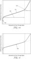
- FIG. 10 is a graph of differential pressure across an exemplary exhalation valve versus volumetric air flow through the valve.
- Curve 101 of the graph shows the typical behavior of differential pressure across the exhalation valve as the flow through the valve varies.
- the graph is divided into three regions based upon different operating modes of the valve.
- first region 100 a valve flap of the valve has been partially lifted or separated from a sealing surface. This region 100 occurs with low air flow through the valve when the valve flap is primarily supported by the sealing surface.
- Second region 102 where the valve flap has fully lifted or separated from the seal surface, occurs with moderate air flow through the valve when the flap is primarily supported by air flow. Parts of the valve flap may also be supported by the seal surface but to a much lesser extent than by the air flow. In this second region 102, the movement of the valve flap away from the seal surface is not constrained by valve body structures such as a valve cap or cover.
- Third region 104 where the valve flap has fully lifted or separated from the seal surface and has been fully deflected, occurs with high air flow through the valve when the flap is supported by air flow and its movement away from the seal surface is restricted by valve body structures such as a valve cap or cover.
- the shape of the second region 102 of the graph shown in FIG. 10 is roughly linear.
- the second region 102 can be approximated by a straight line 106, as is shown in FIG. 11 .
- This straight line 106 can be defined by an appropriate process such as linear regression.
- a differential pressure value that corresponds to a point where the fitted straight line 106 intersect the y-axis i.e., corresponding to a volumetric flow rate of 0
- a slope of the fitted line 106 corresponds to the linear flow resistance of the exhalation valve. This linear flow resistance can indicate the increase in differential pressure resulting from an increase in flow through the exhalation valve.
- respirator exhalation valves should remain closed during inhalation to prevent the leakage of contaminants into the respirator and stay closed when no flow is present and at very low inhalation flow rates.
- the valve flap of the exhalation valve can, in one or more embodiments, have a net force pressing it against the seal surface.
- the exhalation valve can have a finite opening pressure drop as it may not be desirable to have an exhalation valve with a valve opening pressure drop of zero.
- a low-weight flap can be achieved by using a thin, stiff material such as a polymeric film ( see , e.g., U.S. Patent Nos. 7,503,326 and 7,188,622 ).
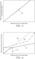
- FIG. 12 is a graph that illustrates a typical relationship between differential pressure and flow rate for a typical face mask that does not include an exhalation valve.
- a linear relationship between air flow rate and differential pressure with a resulting line 108 intersecting the y-axis at the point corresponding to zero flow rate and zero differential pressure.
- This line 108 represents the linear flow resistance of the filter media and other breathable layers of the face mask.
- FIG. 13 is a graph of differential pressure across a typical respirator that includes an exhalation valve versus a volumetric air flow through the respirator.
- a total exhalation flow 112 is the sum of the flow through the exhalation valve and the flow through the breathable layers of the face mask.
- respirator exhalation valve with the lowest possible opening pressure drop and the lowest slope in the linear portion of the valve's pressure/flow relationship. This can result in the greatest amount of exhalation flow through the valve, thereby providing increased comfort for a face mask wearer.
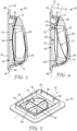
- FIG. 1 is a schematic perspective view of one embodiment of a filtering face mask 10.
- Filtering face mask 10 includes a cup-shaped mask body 12 onto which an exhalation valve 30 is attached.
- the valve 30 may be attached to the mask body using any suitable technique, including, for example, the techniques described in U.S. Patent No. 6,125,849 to Williams et al. or in PCT Publication No. WO2001/28634 to Curran et al.
- the exhalation valve 30 opens in response to increased pressure inside the mask 10, where such increased pressure occurs when a wearer exhales. In one or more embodiments, the exhalation valve 30 remains closed between breaths and during inhalation.
- Mask body 12 is adapted to fit over the nose and mouth of a wearer in spaced relation to the wearer's face to create an interior gas space or void between the wearer's face and the interior surface of the mask body.
- the mask body 12 can be fluid permeable and typically is provided with an opening (not shown) that is located where the exhalation valve 30 is attached to the mask body 12 so that exhaled air can exit the interior gas space through the valve without having to pass through the mask body 12.
- the opening provided for the valve 30 can be disposed in any suitable location on the mask body 12. In one or more embodiments, the opening is disposed directly in front of where the wearer's mouth would be when the mask 10 is being worn.
- essentially an entire exposed surface of mask body 12 is fluid permeable to inhaled air.
- a nose clip 16 that includes a pliable dead soft band of metal such as aluminum can be provided on the mask body 12 to allow it to be shaped to hold the face mask 10 in a desired fitting relationship over the nose of the wearer.
- Any suitable nose clip 16 can be utilized with respirator 10, e.g., the nose clips described in U.S. Patent No. 5,558,089 and Des. 412,573 to Castiglione .
- Mask body 12 can have a curved, hemispherical shape as shown in FIG. 1 ( see also U.S. Patent No. 4,807,619 to Dyrud et al. ) or it may take on other shapes as so desired.
- the mask body 12 can be a cup-shaped mask having a construction like the face mask disclosed in U.S. Patent No. 4,827,924 to Japuntich .
- the respirator 10 can also have a three-panel configuration that can fold flat when not in use but can open into a cup-shaped configuration when worn. See, e.g., U.S. Patent No. 6,123,077 to Bostock et al. ; U.S. Patent Des. 431,647 to Henderson et al.
- Respirators of the present disclosure can also take on many other configurations, such as flat bifold masks disclosed, e.g., in U.S. Pat. Des. 443,927 to Chen .
- the mask body 12 can also be fluid impermeable and have filter cartridges attached to it like the masks described in U.S. Patent No. 5,062,421 to Burns et al.
- the mask body 12 can also be adapted for use with a positive pressure air intake as opposed to the negative pressure masks just described. Examples of positive pressure masks are described, e.g., in U.S. Patent Nos. 5,924,420 to Grannis et al.
- the mask body 12 of the respirator 10 can also be connected to a self-contained breathing apparatus, which supplies filtered air to the wearer as disclosed, e.g., in U.S. Patent Nos. 5,035,239 and 4,971,052 .
- the mask body 12 can be configured to cover not only the nose and mouth of the wearer (referred to as a "half mask") but may also cover the eyes (referred to as a "full face mask”) to provide protection to a wearer's vision as well as to the wearer's respiratory system. See, e.g., U.S. Patent No. 5,924,420 to Reischel et al.
- the mask body 12 may be spaced from the wearer's face, or it may reside flush or in close proximity to it. In either instance, the mask 10 helps define an interior gas space into which exhaled air passes before leaving the mask interior through the exhalation valve 30.
- the mask body 12 can also have a thermochromic fit-indicating seal at its periphery to allow the wearer to easily ascertain if a proper fit has been established. See U.S. Patent No. 5,617,849 to Springett et al.
- mask body 12 can include a harness such as straps 15, tie strings, or any other suitable device attached to it for supporting the mask on the wearer's face.
- harnesses that may be suitable are shown, e.g., in U.S. Patent Nos. 5,394,568 , and 6,062,221 to Brostrom et al. ; and 5,464,010 to Byram .
- FIG. 2 is a schematic cross-section view of a portion of the mask body 12 of FIG. 1 .
- the mask body 12 may include multiple layers such as an inner shaping layer 17 and an outer filtration layer 18.
- Shaping layer 17 provides structure to the mask body 12 and support for filtration layer 18.
- Shaping layer 17 may be located on the inside and/or outside of filtration layer 18 (or on both sides) and can be made, for example, from a nonwoven web of thermally-bondable fibers molded into a cup-shaped configuration. See, e.g., U.S. Patent Nos. 4,807,619 to Dyrud et al. ; and 4,536,440 to Berg .
- the shaping layer 17 can also be made from a porous layer or an open work "fishnet" type network of flexible plastic like the shaping layer disclosed in U.S. Patent No. 4,850,347 to Skov .
- the shaping layer 17 can be molded in accordance with known procedures such as those described in Skov or in U.S. Patent No. 5,307,796 to Kronzer et al.
- a shaping layer 17 is designed with the primary purpose of providing structure to the mask 10 and providing support for the filtration layer 18, the shaping layer can, for example, also act as a filter for capturing larger particles. Together layers 17 and 18 operate as an inhale filter element.
- the filter layer 18 is integral with the mask body 12, i.e., it forms part of the mask body and is not an item that subsequently becomes attached to (or removed from) the mask body like a filter cartridge.
- Filtering materials that are commonplace on negative pressure half mask respirators-like the mask 10 shown in FIG. 1 -often contain an entangled web of electrically charged microfibers, particularly meltblown microfibers (BMF).
- Microfibers typically have an average effective fiber diameter of about 20 micrometers ( ⁇ m) or less, but commonly are about 1 to about 15 ⁇ m, and still more commonly about 3 to 10 ⁇ m in diameter. Effective fiber diameter may be calculated as described in Davies, C. N., The Separation of Airborne Dust and Particles, Institution of Mechanical Engineers, London, Proceedings 1B. 1952 .
- BMF webs can be formed as described in Wente, Van A., Superfine Thermoplastic Fibers in Industrial Engineering Chemistry, vol. 48, pages 1342 et seq.
- BMF webs can have sufficient integrity to be handled as a mat.
- Electric charge can be imparted to fibrous webs using techniques described, e.g., in U.S. Patent. Nos. 5,496,507 to Angadjivand et al. ; 4,215,682 to Kubik et al. ; and 4,592,815 to Nakao .
- fibrous materials that may be used as filters in a mask body are disclosed in U.S. Pat. Nos. 5,706,804 to Baumann et al. ; 4,419,993 to Peterson ; Re 28,102 to Mayhew ; 5,472,481 and 5,411,576 to Jones et al. ; and 5,908,598 to Rousseau et al.
- the fibers may contain polymers such as polypropylene and/or poly-4-methyl-1-pentene ( see, e.g., U.S. Patent Nos. 4,874,399 to Jones et al. ; and 6,057,256 to Dyrud et al.
- Fibers may also have low levels of extractable hydrocarbons to improve performance. See, e.g., U.S. Patent No. 6,213,122 to Rousseau et al. Fibrous webs may also be fabricated to have increased oily mist resistance as described in U.S. Patent Nos. 4,874,399 to Reed et al. ; and 6,238,466 and 6,068,799 to Rousseau et al.
- the mask body 12 may also include inner and/or outer cover webs (not shown) that can protect the filter layer 18 from abrasive forces and that can retain any fibers that may come loose from the filter layer 18 and/or shaping layer 17.
- the cover webs may also have filtering abilities, although typically not nearly as good as the filtering layer 18 and/or may serve to make the mask more comfortable to wear.
- the cover webs may be made from nonwoven fibrous materials such as spun bonded fibers that contain, for example, polyolefins, and polyesters. See, e.g., U.S. Patent Nos. 6,041,782 to Angadjivand et al. ; 4,807,619 to Dyrud et al. ; and 4,536,440 to Berg .
- FIGS. 3-9 are various views of the exhalation valve 30 of FIG. 1 .
- the exhalation valve 30 includes a valve seat 40 and a valve flap 70.
- the valve seat 40 extends along a valve seat axis 32 between a first end 46 and a second end 48 of the valve seat.
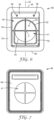
- the valve seat 40 includes a first major surface 42, a second major surface 44, and an orifice 41 disposed between the first and second major surfaces.
- the orifice 41 includes a substantially circular shape in a plane defined by the first major surface 42 of the valve seat 40.
- the valve seat 40 also includes a seal surface 50 and a flap retaining surface 56 disposed on the first major surface 42 of the valve seat.
- the seal surface 50 circumscribes the orifice 41. Further, in one or more embodiments, the seal surface 50 circumscribes the orifice 41 and includes a substantially noncircular shape in the plane defined by the first major surface 42 of the valve seat 40.
- the exhalation valve 30 can also include a cover 80 ( FIG. 9 ) connected to the valve seat 40 using any suitable technique or combination of techniques.
- the valve flap 70 is disposed over the seal surface 50 and the orifice 41. Further, the valve flap 70 includes a first end 72 connected to the flap retaining surface 56. The valve flap 70 is adapted to be sealed against the seal surface 50 of the valve seat 40 when the exhalation valve 30 is disposed in a closed configuration ( FIG. 3 ) such that fluid (e.g., gas) is prevented from flowing through the valve seat.
- the valve flap 70 also includes a second end 74 that is adapted to be spaced apart from the seal surface 50 when the exhalation valve 30 is disposed in an open configuration ( FIG. 4 ) such that fluid can flow through the valve seat 50.
- the valve flap 70 includes a curved shape in a plane orthogonal to the first major surface 42 of the valve seat 40 when the exhalation valve 30 is disposed in the closed configuration ( FIG. 3 ).
- the exhalation valve 30 can be connected to the filtering face mask 10 of FIG. 1 using any suitable technique or combination of techniques.
- an optional base connector 90 can be disposed on an inner surface of the face mask 10
- the valve seat 40 can be disposed on an outer surface of the face mask and connected to the optional base connector through the mask body 12.
- the valve seat 40 can include any suitable material or combination of materials, e.g., metallic, polymeric, etc. Further, any suitable technique or combination of techniques can be utilized to form the valve seat 40. In one or more embodiments, the valve seat 40 can be made from a relatively lightweight plastic that is molded into an integral one-piece body. In one or more embodiments, the valve seat 40 can be made by injection molding techniques. Further, the valve seat 40 can take any suitable shape or combination of shapes and have any suitable dimensions. In one or more embodiments, the valve seat 40 can take a rectangular shape in the plane parallel to the first major surface 42.
- the orifice 41 can be disposed radially inward from the seal surface 50. Further, the orifice 41 is disposed between the first major surface 42 and the second major surface 44 of the valve seat 40 and can take any suitable shape or combination of shapes in a plane defined by the first major surface 42 of the valve seat, e.g., elliptical, rectangular, polygonal, etc. In one or more embodiments, the orifice 41 can include a substantially circular shape. As used herein, the term "substantially circular shape" means that a perimeter 43 ( FIG. 6 ) of the orifice 41 is a smooth and convex closed curve with a continuous first derivative and that the distance from all points on the perimeter from a common central point 2 ( FIG. 6 ) vary by less than 5%.
- the orifice 41 can include a circular shape. Further, the orifice 41 can have any suitable dimensions. In one or more embodiments, a minimum distance from any point on the perimeter 43 to the common central point 2 is at least 0.5 cm and no greater than 2.0 cm. The orifice 41 can be disposed in any suitable location on or through the valve seat 40.
- the valve seat 40 can include cross members 34 disposed within the orifice 41 that can stabilize the seal surface 50 and ultimately the valve 30.
- the cross members 34 can also prevent the valve flap 70 from inverting into orifice 41 during inhalation. Moisture build-up on the cross members 34 can hamper the opening of the flap 70.
- the surfaces of the cross members 34 that face the flap 70 can be slightly recessed beneath the seal surface 50 when viewed from a side elevation to not hamper valve opening.
- the seal surface 50 of the valve seat 40 can be disposed on the first major surface 42 using any suitable technique or combination of techniques.
- the seal surface 50 is integral with the first major surface 42 of the valve seat 40.
- the seal surface 50 can be manufactured separately and connected to the first major surface 42 using any suitable technique or combination of techniques.
- the seal surface 50 can include any suitable material or combination of materials, e.g., the same materials described herein regarding the valve seat 40.
- the seal surface 50 can include one or more materials that are different from the materials utilized to form the valve seat 50.
- the seal surface 50 can circumscribe the orifice 41 such that the seal surface completely surrounds the orifice in the plane defined by the first major surface 42 of the valve seat 40. In one or more embodiments, the seal surface 50 can partially surround the orifice 41.
- the seal surface 50 can take any suitable shape in the plane defined by the first major surface 42 of the valve seat 40, e.g., elliptical, rectangular, polygonal, etc.
- the seal surface 50 can include a substantially noncircular shape.
- the seal surface 50 can include a trapezoidal portion 54 and an elliptical portion 52 connected to the trapezoidal portion as shown in FIG. 6 to provide a rounded trapezoidal shape.
- the elliptical portion 52 can be substantially circular in shape.
- the trapezoidal portion 54 can be substantially rectangular in shape.
- the seal surface 50 can be disposed in any suitable orientation relative to the flap retaining surface 56.
- the elliptical portion 52 of the seal surface 50 is disposed adjacent the flap retaining surface 56.
- adjacent the flap retaining surface means that the element or component is disposed closer to the flap retaining surface 56 than to the second end 48 of the valve seat 40.
- the seal surface 50 can take any suitable shape in the plane defined by the first major surface 42 of the valve seat 40. Further, the seal surface 50 can take any suitable shape in a plane orthogonal to the first major surface 42 of the valve seat 40. For example, as can be seen in FIG. 3 , the seal surface 50 has a concave shape in the plane orthogonal to the first major surface 42 of the valve seat 40. In one or more embodiments, the seal surface 50 can include a non-constant height as measured in a direction normal to the first major surface 42 of the valve seat 40 as is shown in FIG. 4 .
- a first portion 55 of the seal surface 50 adjacent the flap retaining surface 56 has a height 34 that is greater than a height 36 of a second portion 57 of the seal surface that is disposed between a first end 33 and a second and 35 of the seal surface.
- the first end 33 of the seal surface 50 is adjacent the first end 46 of the valve seat 40, and the second end 35 of the seal surface 50 is adjacent the second end 48 of the valve seat.
- the phrase "adjacent the first end 46 of the valve seat 40" means that the element or component is disposed closer to the first end of the valve seat than to the second end of the valve seat.
- the phrase "adjacent the second end 48 of the valve seat 40" means that the element or component is disposed closer to the second end of the valve seat than to the first end of the valve seat.
- any suitable portions of the seal surface 50 can have any suitable height as measured from the first major surface 42 of the valve seat 40.
- An area of the orifice 41 in the plane defined by the first major surface 42 of the valve seat 40 can have any suitable first area. Further, the seal surface 50 can enclose any suitable second area in the plane defined by the first major surface 42 of the valve seat 40. In one or more embodiments, the first area of the orifice 41 is less than the second area of the seal surface 50.
- the orifice 41 can be disposed in any suitable relationship relative to the seal surface 50.
- the perimeter 43 of the orifice 41 can be spaced apart from the seal surface 50 any suitable distance as measured along the first major surface 42 of the valve seat 40.
- the perimeter 43 of the orifice 41 is spaced apart from the seal surface 50 a distance that is no greater than 0.5 cm.
- a portion of the perimeter 43 of the orifice 41 can be spaced apart from a portion of the seal surface 50 a distance 38 ( FIG. 6 ) as measured along the first major surface 42 of the valve seat 40 that is equal to at least 0.1 cm.
- one or more portions of the perimeter 40 through the orifice 41 can be coincident with the seal surface 50 as measured along the first major surface 42 of the valve seat 40.
- the term "coincident" means that a portion or portions of the perimeter 43 of the orifice 41 follows a shape of the seal surface 50 such that there is no distance or space between such portions of the perimeter and the seal surface. For example, as shown in FIG. 6 , portion 47 of perimeter 43 is coincident with portion 53 of seal surface 50. Any suitable percentage of the perimeter 43 of the orifice 41 can be coincident with the seal surface 50 as measured along the first major surface 42 of the valve seat 40.
- no greater than 75% of the perimeter 43 of the orifice 41 is coincident with the seal surface 50. In one or more embodiments, no greater than 50% of the perimeter 43 of the orifice 41 is coincident with the seal surface 50. Further, in one or more embodiments, no greater than 25% of the perimeter 43 of the orifice 41 is coincident with the seal surface 50. Further, in one or more embodiments, no greater than 10% of the perimeter 43 is coincident with the seal surface 50.
- the seal surface 50 that makes contact with the flap 70 can be formed to be substantially uniformly smooth to ensure that a good seal occurs and may reside on the top of the surface.
- the seal surface 50 can have a width great enough to form a seal with the valve flap 70 but is not so wide as to allow adhesive forces caused by condensed moisture to make the flap significantly more difficult to open.
- a width of the seal surface 50 can be at least 0.2 mm and no greater than 0.5 mm.
- the valve flap 70 is disposed over the seal surface 50 and the orifice 41.
- the valve flap 70 includes the first end 72 connected to the flap retaining surface 56 using any suitable technique or combination of techniques.
- the flap retaining surface 56 can include one or more posts 58 that are adapted to engage openings 76 of the valve flap 70 that are disposed adjacent the first end 72 of the flap.
- the valve flap 70 can be secured to the surface 56, e.g., using sonic welding, an adhesive, mechanical clamping, etc.
- valve flap 70 includes the second end 74 that is adapted to be spaced apart from the seal surface 50 when the exhalation valve 10 is disposed in an open configuration as shown in FIG. 4 such that fluid (e.g., gas) can flow through the valve seat 40.
- fluid e.g., gas
- the flap 70 lifts from the seal surface 50 at its free end 74 when a significant pressure is reached in the interior gas space of the face mask 10 during an exhalation.
- the seal surface 50 can be adapted to generally curve in a direction parallel to the valve seat axis 32 such that it has a concave cross-section when viewed from a side elevation and may be non-aligned and relatively positioned with respect to a flap retaining surface 56 to allow the flap to be biased or pressed towards the seal surface under neutral conditions, i.e., when the wearer is neither inhaling or exhaling.
- the flap 70 can also have a transverse curvature imparted to it as described, e.g., in U.S. Patent No. 5,687,767 , reissued as Re 37,974 to Bowers .
- valve flap 70 is adapted be sealed against the seal surface 50 of the valve seat 40 when the exhalation valve 10 is disposed in the close configuration as shown in FIG. 3 such that fluid is prevented from flowing through the valve seat.
- the valve flap 70 can include a curved shape in a plane orthogonal to the first major surface 42 of the valve seat 40 when the exhalation valve 30 is disposed in the closed configuration as shown in FIG. 3 .
- the valve flap 70 can take any suitable shape or combination of shapes in a plane defined by the first major surface 42 of the valve seat 40.
- a width 78 of the first end 72 of the valve flap 70 is less than a width 79 of the second end 74 the valve flap as measured along a direction orthogonal to the valve seat axis 32 when the flap is connected to the flap retaining surface 56.
- the width 78 of the first end 72 is greater than the width 79 of the second end 74 the valve flap 70.
- the valve flap 70 can take any suitable shape or combination of shapes in the plane shown in FIG. 8 , e.g., elliptical, rectangular, polygonal, etc.
- the valve flap 70 can include a shape in the plane defined by the first major surface 42 of the valve seat 40 that corresponds to the shape of the seal surface 50 in the same plane.
- the term "corresponds" means that the shape of the valve flap 70 is substantially the same as the shape of the seal surface 50 but can have differing overall dimensions, e.g., the shape and dimensions of the valve flap can be selected such that the valve flap covers the seal surface when in the closed configuration.
- the first end 72 of the valve flap 70 is connected to the flap retaining surface 56, which can, in one or more embodiments, be substantially disposed in a plane 81 that forms an angle 31 with the valve seat axis 32 as is shown in FIG. 4 .
- Angle 31 can have any suitable value. In one or more embodiments, angle 31 can be greater than 0 degrees such that the valve flap 70 is cantilevered in relation to the first major surface 42 of the valve seat 40.
- This cantilevered arrangement of the flap retaining surface 56 can provide the flap 70 with a curved shape in the plane orthogonal to the first major surface 42 of the valve seat 40 as shown in FIG. 3 .
- the valve flap 70 can include any suitable material or combination of materials, e.g., metallic, polymeric, etc. Further, the valve flap 70 can include a single layer of material. In one or more embodiments, the valve flap can include two more layers of material as is described, e.g., in US Patent No. 7,028,689 to Martin et al. entitled FILTERING FACE MASK THAT USES AN EXHALATION VALVE THAT HAS A MULTILAYERED FLEXIBLE FLAP. In one or more embodiments, the valve flap 70 can include a multilayer optical film as is also described in US Patent No. 7,028,689 . The valve flap 70 can include any suitable coating or coatings.
- Such coatings can, in one or more embodiments, promote a good seal between the valve flap 70 and the seal surface 50.
- Suitable coatings can include elastomers, both thermoset and thermoplastic, and thermoplastic/plastomers.
- Elastomers which may be either thermoplastic elastomers or crosslinked rubbers, may include rubber materials such as polyisoprene, poly(styrene-butadiene) rubber, polybutadiene, butyl rubber, ethylene-propylene-diene rubber, ethylene-propylene rubber, nitrile rubber, polychloroprene rubber, chlorinated polyethylene rubber, chlorosulphonated polyethylene rubber, polyacrylate elastomer, ethylene-acrylic rubber, fluorine containing elastomers, silicone rubber, polyurethane, epichlorohydrin rubber, propylene oxide rubber, polysulphide rubber, polyphosphazene rubber, and latex rubber, styrene-butadienestyrene block
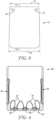
- the exhalation valve 30 can include a cover 80 ( FIG. 9 ).
- the cover 80 can be connected to the valve seat 40 using any suitable technique or combination of techniques.
- the valve seat 40 can include a cover retaining surface 60 that extends from the first major surface 42 of the valve seat 40 ( FIGS. 5-6 ).
- the cover retaining surface 60 can take any suitable shape or combination of shapes. Further, the cover retaining surface 60 can have any suitable dimensions.
- the cover retaining surface 60 can be integral with the first major surface 42 of the valve seat 40.
- the cover retaining surface 60 can be manufactured separately and attached to the first major surface 42 of the valve seat 40 using any suitable technique or combination of techniques.
- the valve cover 80 is press fit onto the valve seat 40 such that a friction fit is formed between the cover retaining surface 60 and an interior surface of the valve cover 80.
- the valve cover 80 is adapted to be connected to the valve seat 40 and disposed over the valve flap 70 and at least a portion of the first major surface 42 of the valve seat.
- the valve cover 80 can include an opening or openings in fluid communication with the orifice 41 when exhalation valve 30 is disposed in the open configuration as shown in FIG. 4 .
- the valve cover 80 includes side openings 82 and front openings 84.
- the side openings 82 and the front openings 84 can take any suitable shape or combination of shapes. In one or more embodiments, the side openings 82 take the same shape as the front openings 84.
- the shape of the side openings 82 is different from the shape of the front openings 84.
- the front openings 84 can have the same shape or different shapes.
- front openings 84 include large openings 87 and small openings 88 disposed between the large openings.
- the side and front openings 82, 84 can have any suitable dimensions.
- the cover 80 can take any suitable shape in the plane defined by the first major surface 42 of the valve seat 40. Further, the cover 80 can take any suitable shape or combination of shapes in a plane orthogonal to the first major surface 42. For example, as shown in FIGS 3-4 , the valve cover 80 can take a curved shape that has a height measured in a direction orthogonal to the first major surface 42 of the valve seat 40 that varies in a direction between the first end 46 and the second end 48 of the valve seat.
- the cover 80 can include a surface 86 that is adapted to engage the flap 70 such that the flap is retained against the flap retaining surface 56 of the valve seat 40. Further, the cover 80 can include one or more flap stops 83 disposed on an inner surface 85 of the valve cover. The flap stops 83 can take any suitable shape or combination of shapes and be located in any suitable location on the inner surface 85 of the valve cover 80. In one or more embodiments, the flap stops 83 are adapted to engage the second end 74 of the valve flap 70 when the exhalation valve 30 is in the open configuration to prevent the valve flap from becoming completely engaged with the inner surface 85 of the cover, where such engagement with the inner surface may prevent the valve flap from returning to the closed configuration. In one or more embodiments, such engagement between the valve flap 70 and the inner surface 85 of the cover 80 can be caused by moisture that forms on one or both of the valve flap and the cover.
- the exhaled air commonly passes through both the mask body 12 and the exhalation valve 30. Comfort can be improved when the highest percentage of the exhaled air passes through the exhalation valve 30, as opposed to the filter media and/or shaping and cover layers of the mask body 12. Exhaled air is expelled from the interior gas space through the orifice 41 of the valve 30 by having the exhaled air lift the valve flap 70 from the seal surface 50. The fluid that passes through the orifice 41 exerts a force on the flap 70, causing the free end 74 of the flap to be lifted from seal surface 50 to make the valve 30 open.
- valve 30 When valve 30 is used as an exhalation valve, the valve can be oriented on face mask 10 such that the free end 74 of flap 70 is located below the secured end when the mask 10 is positioned upright as shown in FIG. 1 . This enables exhaled air to be deflected downwards to prevent moisture from condensing on the wearer's eyewear.
- the various embodiments of exhalation valves described herein can provide any desired valve of pressure drop.
- the pressure drop may be determined in accordance with the Pressure Drop Test set forth herein.
- multi-layered flexible flaps may enable the inventive unidirectional fluid valve to have a pressure drop of less than 30 Pa, preferably less than 25 Pa, and more preferably less than 20 Pa.
- Pressure drops of about 5 to 50 Pa may be obtainable between flow rates of 10 L/min and 85 L/min using multi-layer flexible flaps in accordance with the present invention.
- the pressure drop may be less than 25 Pa over flow rates of 10 L/min to 85 L/min.
- the valve opening pressure drop measures the resistance to the initial lifting of the flap from the valve's seal surface. This parameter may be determined as described below in the Pressure Drop Test.
- the valve opening pressure drop at 10 L/min is less than 30 Pa, preferably less than 25 Pa, and more preferably less than 20 Pa when testing a valve in accordance with the Pressure Drop Test described below.
- the valve opening pressure drop is about 5 to 30 Pa at 10 L/min when testing a valve in accordance with the Pressure Drop Test described below.
- Prototype valve seats were provided utilizing stereolithography (SLA) rapid prototyping.
- the overall valve size was similar to the existing valve sold under the trade designation "CoolFlow” (available from 3M Company, Et. Paul, MN, and utilized in respirators sold under the trade designation “Particulate Respirator 8511,” also available from 3M Company).
- the valve seats are listed in Table 1 below.
- the "rounded trapezoid" shape refers to the shape of the sealing surface 56 as illustrated in FIG. 6 .
- Example 2 was created by attaching a sheet of plastic with a round hole similar in size and position to the orifice in the Comparative Example 1.
- Table 1 Prototype valve seat descriptions Valve Seats Sealing Surface Shape Orifice Shape Comparative Example 1 Round Round Comparative Example 2 Rounded Trapezoid Rounded Trapezoid Example Rounded Trapezoid Round
- the Comparative Examples 1-2 and the Example were used to assemble exhalation valves that included valve flaps and covers.
- the valve flaps were composed of 0.05 mm thick multilayer optical film coated on one side with a 0.05 mm thick coating of SBS rubber (available from Dexco Polymers, Plaquemine, LA, USA). When assembled, the coated side of the valve flap was placed against a sealing surface of each of the valve seats.
- the samples were tested on a pressure/flow test system composed of a 50 L/min electronic flow controller (available from MKS Instruments, Andover, MA), high resolution differential pressure transducer (available from Omega Engineering Inc., Stamford, CT), a valve test fixture and a personal computer running Windows 7 operating system. Compressed air was supplied to the flow controller at approximately 250 kPa, and the flow controller was attached the test fixture. The pressure transducer was attached to the test fixture to measure the differential pressure between the upstream and downstream sides of the valve installed in the test fixture. The computer ran a test program that controlled the flow controller and acquired measured flow and differential pressure data using a data acquisition interface (National Instruments Corporation, Austin, TX, USA).
- a data acquisition interface National Instruments Corporation, Austin, TX, USA.
- the Example had a significantly lower opening differential pressure than that of Comparative Example 1. While not wishing to be bound by any particular theory, this difference in pressure can be caused by a greater moment arm of the valve flap on the extended "rounded trapezoid" sealing surface of the Example.
- Comparative Example 2 had an opening differential pressure that was slightly lower than the Example because Comparative Sample has the same "rounded trapezoid" sealing surface as the Example. The presence of the rounded orifice in the Example increased the opening differential pressure by 0.4 Pa, or 7%, which is small compared to the increase in Comparative Example 1 of 3.4 Pa, or 60%.
Landscapes
- Health & Medical Sciences (AREA)
- General Health & Medical Sciences (AREA)
- Business, Economics & Management (AREA)
- Emergency Management (AREA)
- Pulmonology (AREA)
- Engineering & Computer Science (AREA)
- General Engineering & Computer Science (AREA)
- Zoology (AREA)
- Life Sciences & Earth Sciences (AREA)
- Mechanical Engineering (AREA)
- Physical Education & Sports Medicine (AREA)
- Textile Engineering (AREA)
- Respiratory Apparatuses And Protective Means (AREA)
- Check Valves (AREA)
Claims (15)
- Soupape d'expiration (30), comprenant :un siège de soupape (40) comprenant une première surface principale (42), une seconde surface principale (44), un orifice (41) disposé entre les première et seconde surfaces principales du siège de soupape, et un axe de siège de soupape (32) s'étendant entre une première extrémité (46) et une seconde extrémité (48) du siège de soupape, dans lequel l'orifice a une forme essentiellement circulaire dans un plan défini par la première surface principale du siège de soupape, dans lequel le siège de soupape comprend en outre une surface d'étanchéité (50) et une surface de retenue du clapet (56) disposée chacune sur la première surface principale du siège de soupape, dans lequel la surface d'étanchéité entoure l'orifice et comprend une forme essentiellement non circulaire dans le plan défini par la première surface principale du siège de soupape ; etun clapet de soupape (70) disposé sur la surface d'étanchéité (50) et l'orifice (41) et comprenant une première extrémité (72) raccordée à la surface de retenue du clapet (56), dans lequel le clapet de soupape est conçu pour être scellé contre la surface d'étanchéité du siège de soupape lorsque la soupape d'expiration est disposée dans une configuration fermée (Figure 3) de telle sorte que le fluide est empêché de s'écouler à travers le siège de soupape (50), dans lequel une seconde extrémité (74) du clapet de soupape (70) est conçue pour être espacée de la surface d'étanchéité lorsque la soupape d'expiration est disposée dans une configuration ouverte (Figure 4) de telle sorte que le fluide peut s'écouler à travers le siège de soupape (50), et dans lequel en outre le clapet de soupape comprend une forme incurvée dans un plan orthogonal à la première surface principale du siège de soupape lorsque la soupape d'expiration est disposée dans la configuration fermée ;dans laquelle une ou plusieurs parties d'un périmètre (40) à travers l'orifice (41) coïncident avec la surface d'étanchéité (50) telle que mesurée le long de la première surface principale (42) du siège de soupape (40).dans laquelle pas plus de 75 % du périmètre (43) de l'orifice (41) coïncide avec la surface d'étanchéité (50) telle que mesurée dans le plan défini par la première surface principale (42) du siège de soupape (40).
- Soupape d'expiration (30) selon la revendication 1, dans laquelle la surface de retenue de clapet (56) est disposée de manière adjacente à la première extrémité (46) du siège de soupape (40).
- Soupape d'expiration (30) selon la revendication 1 ou 2, dans laquelle l'orifice (41) comprend une première zone dans le plan défini par la première surface principale (42) du siège de soupape (40), dans laquelle la surface d'étanchéité (50) comprend une seconde zone dans le plan défini par la première surface principale, dans laquelle la première zone est inférieure à la seconde zone.
- Soupape d'expiration (30) selon l'une quelconque des revendications 1 à 3, dans laquelle le périmètre (43) de l'orifice (41) est espacé de la surface d'étanchéité (50) d'une distance qui n'est pas supérieure à 0,5 cm telle que mesurée le long de la première surface principale (42) du siège de soupape (40).
- Soupape d'expiration (30) selon la revendication 4, dans laquelle une partie du périmètre (43) de l'orifice (41) est espacée d'une partie de la surface d'étanchéité (50) d'une distance qui est égale à 0,1 cm telle que mesurée le long de la première surface principale (42) du siège de soupape (40).
- Soupape d'expiration (30) selon la revendication 1, dans laquelle pas plus de 25 % du périmètre (43) de l'orifice (41) coïncide avec la surface d'étanchéité (50) telle que mesurée dans le plan défini par la première surface principale (42) du siège de soupape (40).
- Soupape d'expiration (30) selon l'une quelconque des revendications 1 à 6, dans laquelle la surface d'étanchéité (50) comprend une forme concave dans un plan orthogonal à la première surface principale (42) du siège de soupape (40).
- Soupape d'expiration (30) selon l'une quelconque des revendications 1 à 7, dans laquelle la surface d'étanchéité (50) comprend une hauteur non constante telle que mesurée dans une direction normale à la première surface principale (42) du siège de soupape (40).
- Soupape d'expiration (30) selon la revendication 8, dans laquelle une hauteur d'une première partie de la surface d'étanchéité (50) adjacente à la surface de retenue du clapet (56) est supérieure à une hauteur d'une seconde partie de la surface d'étanchéité disposée entre une première extrémité et une seconde extrémité de la surface d'étanchéité (50), dans laquelle la première extrémité de la surface d'étanchéité est adjacente à la première extrémité (46) du siège de soupape (40) et la seconde extrémité de la surface d'étanchéité est adjacente à la seconde extrémité (48) du siège de soupape (40).
- Soupape d'expiration (30) selon l'une quelconque des revendications 1 à 9, dans laquelle le clapet de soupape (70) comprend deux couches ou plus.
- Soupape d'expiration (30) selon la revendication 10, dans laquelle le clapet de soupape (70) comprend en outre un revêtement élastomère.
- Soupape d'expiration (30) selon l'une quelconque des revendications 1 à 11, dans laquelle le clapet de soupape (70) comprend un film optique multicouche.
- Soupape d'expiration (30) selon l'une quelconque des revendications 1 à 12, dans laquelle le clapet de soupape (70) comprend une forme dans le plan défini par la première surface principale (42) du siège de soupape (40) qui correspond à la forme de la surface d'étanchéité (50) dans le plan défini par la première surface principale du siège de soupape.
- Soupape d'expiration (30) selon l'une quelconque des revendications 1 à 13, dans laquelle la surface d'étanchéité (50) comprend une partie trapézoïdale (54) et une partie elliptique (52) reliée à la partie trapézoïdale, dans laquelle la partie elliptique est disposée de manière adjacente à la surface de retenue du clapet (56).
- Masque facial filtrant (10) comprenant :un corps de masque (12) qui est conçu pour s'ajuster au moins pardessus le nez et la bouche d'un porteur pour former un espace de gaz intérieur lorsqu'il est porté ;soupape d'expiration (30) selon l'une quelconque des revendications 1 à 14, dans laquelle la soupape d'expiration est en communication fluidique avec l'espace de gaz intérieur.
Applications Claiming Priority (2)
| Application Number | Priority Date | Filing Date | Title |
|---|---|---|---|
| US201662395429P | 2016-09-16 | 2016-09-16 | |
| PCT/US2017/051066 WO2018052874A1 (fr) | 2016-09-16 | 2017-09-12 | Soupape d'expiration et appareil respiratoire comprenant ladite soupape d'expiration |
Publications (2)
| Publication Number | Publication Date |
|---|---|
| EP3512608A1 EP3512608A1 (fr) | 2019-07-24 |
| EP3512608B1 true EP3512608B1 (fr) | 2023-12-06 |
Family
ID=59982479
Family Applications (1)
| Application Number | Title | Priority Date | Filing Date |
|---|---|---|---|
| EP17777443.7A Active EP3512608B1 (fr) | 2016-09-16 | 2017-09-12 | Soupape d'expiration et appareil respiratoire comprenant ladite soupape d'expiration |
Country Status (10)
| Country | Link |
|---|---|
| US (1) | US12070634B2 (fr) |
| EP (1) | EP3512608B1 (fr) |
| JP (1) | JP6949944B2 (fr) |
| KR (1) | KR102558116B1 (fr) |
| CN (1) | CN109715252B (fr) |
| CA (1) | CA3036977A1 (fr) |
| CO (1) | CO2019002377A2 (fr) |
| MX (1) | MX2019002849A (fr) |
| RU (1) | RU2719873C1 (fr) |
| WO (1) | WO2018052874A1 (fr) |
Families Citing this family (12)
| Publication number | Priority date | Publication date | Assignee | Title |
|---|---|---|---|---|
| KR102147572B1 (ko) * | 2018-07-31 | 2020-08-25 | 이영희 | 온수 역순환 방지기능을 갖춘 전기온수매트용 보일러장치 |
| KR102360153B1 (ko) * | 2019-06-12 | 2022-02-08 | (주)씨앤투스성진 | 배기밸브가 구비된 마스크 |
| CN110169614A (zh) * | 2019-06-28 | 2019-08-27 | 华新医材股份有限公司 | 吸食防护口罩及其阀结构 |
| CN110368612B (zh) * | 2019-07-25 | 2024-05-14 | 上海宝亚安全装备股份有限公司 | 一种无需工具可拆卸呼气阀的面罩及其安装拆卸方法 |
| IT202000009118A1 (it) * | 2020-04-27 | 2021-10-27 | Motordesign Modena S R L | Procedimento per la produzione di manufatti in materiale composito |
| US20210353977A1 (en) * | 2020-05-13 | 2021-11-18 | D. Wheatley Enterprises, Inc. | Integrated respiratory and eye protective system |
| KR200493338Y1 (ko) * | 2020-05-14 | 2021-03-16 | 주식회사 민성정밀 | 마스크 밸브 |
| KR102485422B1 (ko) * | 2020-06-30 | 2023-01-06 | 엘지전자 주식회사 | 마스크 장치 |
| EP3978081A1 (fr) | 2020-09-30 | 2022-04-06 | Moldex-Metric AG & Co. KG | Masque respiratoire pourvu de soupape à disques |
| KR102408131B1 (ko) * | 2021-01-30 | 2022-06-14 | 유한회사 에어하이진 | 필름형 흡배기 밸브 및 상기 필름형 흡배기 밸브가 장착되며, 들숨공간과 날숨공간이 분리된 호흡용 필터 카트리지 |
| GB202108588D0 (en) * | 2021-06-16 | 2021-07-28 | Globus Shetland Ltd | Valve assembly |
| KR102710258B1 (ko) * | 2024-02-14 | 2024-09-26 | 주식회사 커버바이오 | 산소 발생 부재를 포함하는 산업용 방진 마스크 |
Family Cites Families (98)
| Publication number | Priority date | Publication date | Assignee | Title |
|---|---|---|---|---|
| US1268696A (en) | 1918-02-06 | 1918-06-04 | Robert Donald | Respirator or inhaler. |
| US2072516A (en) | 1934-02-08 | 1937-03-02 | American Mach & Foundry | Insert attachment for wrapping machines |
| US2230770A (en) | 1939-12-09 | 1941-02-04 | Cons Car Heating Co Inc | Circuit controller |
| US2895472A (en) | 1956-01-05 | 1959-07-21 | Electric Storage Battery Co | Respirator |
| GB825659A (en) | 1956-11-14 | 1959-12-16 | P B Cow & Company Ltd | Valves for use in breathing appliances |
| US2999498A (en) | 1957-05-07 | 1961-09-12 | Electric Storage Battery Co | Respirator |
| FR1475015A (fr) | 1966-02-18 | 1967-03-31 | Commissariat Energie Atomique | Dispositif d'expiration pour masques respiratoires |
| US3613678A (en) | 1970-02-24 | 1971-10-19 | Minnesota Mining & Mfg | Filtration mask |
| US4215682A (en) | 1978-02-06 | 1980-08-05 | Minnesota Mining And Manufacturing Company | Melt-blown fibrous electrets |
| US4850347A (en) | 1980-06-09 | 1989-07-25 | Metric Products, Inc. | Face mask |
| US4414973A (en) | 1981-03-10 | 1983-11-15 | U.S.D. Corp. | Respirator face mask |
| US4419993A (en) | 1981-12-10 | 1983-12-13 | Minnesota Mining & Manufacturing Company | Anti-fogging surgical mask |
| US4729371A (en) | 1983-10-11 | 1988-03-08 | Minnesota Mining And Manufacturing Company | Respirator comprised of blown bicomponent fibers |
| JPS6097123U (ja) | 1983-12-10 | 1985-07-02 | 株式会社モリタ製作所 | 歯科治療台 |
| JPS60168511A (ja) | 1984-02-10 | 1985-09-02 | Japan Vilene Co Ltd | エレクトレツトフイルタの製造方法 |
| US4536440A (en) | 1984-03-27 | 1985-08-20 | Minnesota Mining And Manufacturing Company | Molded fibrous filtration products |
| GB8428640D0 (en) | 1984-11-13 | 1984-12-19 | Avon Ind Polymers | Valve for respirator |
| US4630604A (en) | 1985-04-09 | 1986-12-23 | Siebe North, Inc. | Valve assembly for a replaceable filter respirator |
| US4807619A (en) | 1986-04-07 | 1989-02-28 | Minnesota Mining And Manufacturing Company | Resilient shape-retaining fibrous filtration face mask |
| US5099026A (en) | 1986-09-12 | 1992-03-24 | Crater Davis H | Fluorochemical oxazolidinones |
| US5025052A (en) | 1986-09-12 | 1991-06-18 | Minnesota Mining And Manufacturing Company | Fluorochemical oxazolidinones |
| EP0266456A1 (fr) | 1986-11-06 | 1988-05-11 | Moldex-Metric AG & Co.KG | Masque respiratoire |
| US4749003A (en) | 1987-01-22 | 1988-06-07 | Filtertek, Inc. | Center flow check valve |
| US4827924A (en) | 1987-03-02 | 1989-05-09 | Minnesota Mining And Manufacturing Company | High efficiency respirator |
| US4934362A (en) | 1987-03-26 | 1990-06-19 | Minnesota Mining And Manufacturing Company | Unidirectional fluid valve |
| US4790306A (en) | 1987-09-25 | 1988-12-13 | Minnesota Mining And Manufacturing Company | Respiratory mask having a rigid or semi-rigid, insert-molded filtration element and method of making |
| US5062421A (en) | 1987-11-16 | 1991-11-05 | Minnesota Mining And Manufacturing Company | Respiratory mask having a soft, compliant facepiece and a thin, rigid insert and method of making |
| US4874399A (en) | 1988-01-25 | 1989-10-17 | Minnesota Mining And Manufacturing Company | Electret filter made of fibers containing polypropylene and poly(4-methyl-1-pentene) |
| US4838262A (en) | 1988-05-02 | 1989-06-13 | Mine Safety Appliances Company | Exhalation valve |
| GB8815179D0 (en) | 1988-06-25 | 1988-08-03 | Racal Safety Ltd | Differential pressure sensor |
| GB2221164B (en) | 1988-07-26 | 1992-02-12 | Racal Safety Ltd | Breathing apparatus |
| US4981134A (en) | 1990-01-16 | 1991-01-01 | Courtney Darryl W | Filtering face mask with inhalation/exhalation check valves |
| DE4029939A1 (de) | 1990-09-21 | 1992-03-26 | Am Produkte Gmbh | Ventil fuer staubschutzmasken |
| US5307796A (en) | 1990-12-20 | 1994-05-03 | Minnesota Mining And Manufacturing Company | Methods of forming fibrous filtration face masks |
| JP3359033B2 (ja) | 1992-05-29 | 2002-12-24 | ミネソタ マイニング アンド マニュファクチャリング カンパニー | 逆止弁 |
| US5325892A (en) | 1992-05-29 | 1994-07-05 | Minnesota Mining And Manufacturing Company | Unidirectional fluid valve |
| US5394568A (en) | 1993-01-28 | 1995-03-07 | Minnesota Mining And Manufacturing Company | Molded head harness |
| US5331957A (en) | 1993-02-05 | 1994-07-26 | Liu Chin Chia | Respirator for only filtering air inhaled |
| AU669420B2 (en) | 1993-03-26 | 1996-06-06 | Minnesota Mining And Manufacturing Company | Oily mist resistant electret filter media |
| JP3476084B2 (ja) | 1993-08-17 | 2003-12-10 | ミネソタ マイニング アンド マニュファクチャリング カンパニー | エレクトレット濾過材の荷電方法 |
| US5464010A (en) | 1993-09-15 | 1995-11-07 | Minnesota Mining And Manufacturing Company | Convenient "drop-down" respirator harness structure and method of use |
| CN1107467C (zh) | 1994-10-13 | 2003-05-07 | 美国3M公司 | 口罩鼻夹 |
| USD412573S (en) | 1994-10-14 | 1999-08-03 | 3M Innovative Properties Company | Nose clip for a filtering face mask |
| JP4130474B2 (ja) | 1995-03-09 | 2008-08-06 | スリーエム カンパニー | 呼吸器保護装置およびその作製方法 |
| GB2304176B (en) * | 1995-08-04 | 1999-08-18 | Racal Health & Safety Ltd | Uni-directional fluid valve |
| GB9515986D0 (en) | 1995-08-04 | 1995-10-04 | Racal Health & Safety Ltd | Uni-directional fluid valve |
| US5908598A (en) | 1995-08-14 | 1999-06-01 | Minnesota Mining And Manufacturing Company | Fibrous webs having enhanced electret properties |
| US5617849A (en) | 1995-09-12 | 1997-04-08 | Minnesota Mining And Manufacturing Company | Respirator having thermochromic fit-indicating seal |
| USD424688S (en) | 1996-09-06 | 2000-05-09 | 3M Innovative Properties Company | Respiratory protection mask |
| USD431647S (en) | 1996-09-06 | 2000-10-03 | 3M Innovative Properties Company | Personal respiratory protection device having an exhalation valve |
| US5924420A (en) | 1996-09-24 | 1999-07-20 | Minnesota Mining And Manufacturing Company | Full face respirator mask having integral connectors disposed in lens area |
| US5706804A (en) | 1996-10-01 | 1998-01-13 | Minnesota Mining And Manufacturing Company | Liquid resistant face mask having surface energy reducing agent on an intermediate layer therein |
| US6041782A (en) | 1997-06-24 | 2000-03-28 | 3M Innovative Properties Company | Respiratory mask having comfortable inner cover web |
| FR2767482B1 (fr) | 1997-08-20 | 1999-10-29 | Graham Hamilton Millar | Dispositif souffleur incorpore dans un masque anti-poussiere |
| US6213122B1 (en) | 1997-10-01 | 2001-04-10 | 3M Innovative Properties Company | Electret fibers and filter webs having a low level of extractable hydrocarbons |
| US6238466B1 (en) | 1997-10-01 | 2001-05-29 | 3M Innovative Properties Company | Electret articles and filters with increased oily mist resistance |
| US6068799A (en) | 1997-10-01 | 2000-05-30 | 3M Innovative Properties Company | Method of making electret articles and filters with increased oily mist resistance |
| US6062221A (en) | 1997-10-03 | 2000-05-16 | 3M Innovative Properties Company | Drop-down face mask assembly |
| GB9723740D0 (en) | 1997-11-11 | 1998-01-07 | Minnesota Mining & Mfg | Respiratory masks incorporating valves or other attached components |
| US6432175B1 (en) | 1998-07-02 | 2002-08-13 | 3M Innovative Properties Company | Fluorinated electret |
| US6047698A (en) * | 1998-08-20 | 2000-04-11 | Moldex-Metric, Inc. | Unidirectional fluid valve |
| USD443927S1 (en) | 1999-02-17 | 2001-06-19 | 3M Innovative Properties Company | Respiratory mask |
| US6604524B1 (en) | 1999-10-19 | 2003-08-12 | 3M Innovative Properties Company | Manner of attaching component elements to filtration material such as may be utilized in respiratory masks |
| US6883518B2 (en) * | 2001-06-25 | 2005-04-26 | 3M Innovative Properties Company | Unidirectional respirator valve |
| EP1275412B1 (fr) | 2001-06-27 | 2008-04-16 | Fisher & Paykel Healthcare Limited | Valve d'expiration pour un masque respiratoire nasal |
| US7028689B2 (en) * | 2001-11-21 | 2006-04-18 | 3M Innovative Properties Company | Filtering face mask that uses an exhalation valve that has a multi-layered flexible flap |
| US20040040562A1 (en) * | 2002-08-28 | 2004-03-04 | Brunell Robert A. | Mask and spherically configured valve |
| US20040261795A1 (en) | 2002-08-28 | 2004-12-30 | Brunell Robert A. | Respirator mask and valve |
| WO2004112906A1 (fr) | 2003-06-17 | 2004-12-29 | Louis M. Gerson Co., Inc. | Masque respiratoire et soupape |
| US7188622B2 (en) | 2003-06-19 | 2007-03-13 | 3M Innovative Properties Company | Filtering face mask that has a resilient seal surface in its exhalation valve |
| US7769652B1 (en) | 2003-08-29 | 2010-08-03 | Trading Technologies International, Inc. | System and method for changing order priority levels in an electronic trading environment |
| JP4089584B2 (ja) | 2003-10-01 | 2008-05-28 | 日立工機株式会社 | 圧縮空気ねじ締め機 |
| ITPS20040007A1 (it) | 2004-02-18 | 2004-05-18 | Cl Com Advanced Tecnology Srl | Maschera di protezione contro gli agenti biologici |
| US6834649B1 (en) * | 2004-04-13 | 2004-12-28 | Tzong-Fuh Kuo | One-way valve on diving mask |
| DE502004004668D1 (de) | 2004-10-15 | 2007-09-27 | Moldex Metric Ag & Co Kg | Atemschutzmaske mit Ausatemventil |
| US7503326B2 (en) | 2005-12-22 | 2009-03-17 | 3M Innovative Properties Company | Filtering face mask with a unidirectional valve having a stiff unbiased flexible flap |
| US20090044811A1 (en) | 2007-08-16 | 2009-02-19 | Kimberly-Clark Worldwide, Inc. | Vent and strap fastening system for a disposable respirator providing improved donning |
| AU2008293810B2 (en) | 2007-08-31 | 2011-10-06 | 3M Innovative Properties Company | Unitary respirator with molded thermoset elastomeric elements |
| CN102553097A (zh) | 2007-11-27 | 2012-07-11 | 3M创新有限公司 | 具有单向阀的面罩 |
| KR100912233B1 (ko) | 2008-12-12 | 2009-08-14 | (주)피앤티디 | 마스크 |
| WO2011026515A1 (fr) | 2009-09-02 | 2011-03-10 | John Ribchester | Masque de visage |
| US8365771B2 (en) * | 2009-12-16 | 2013-02-05 | 3M Innovative Properties Company | Unidirectional valves and filtering face masks comprising unidirectional valves |
| US7958889B1 (en) | 2010-01-15 | 2011-06-14 | Aurora L. Fernandez de Castro | Protective face cover and moldable attachment |
| RU2013125285A (ru) * | 2010-12-29 | 2015-02-10 | 3М Инновейтив Пропертиз Компани | Респиратор, содержащий клапан с аблированной створкой |
| KR101348238B1 (ko) * | 2012-02-10 | 2014-01-22 | (주)씨앤투스이지스 | 마스크용 배기밸브 |
| CN202751705U (zh) | 2012-09-03 | 2013-02-27 | 上海港凯净化制品有限公司 | 一种呼吸阀结构 |
| AU2014290207B2 (en) | 2013-07-15 | 2017-05-11 | 3M Innovative Properties Company | Respirator having optically active exhalation valve |
| CN106456919A (zh) | 2014-05-26 | 2017-02-22 | 创烁私人有限公司 | 用于贴附主动排放系统的具有单向阀的呼吸罩装置 |
| CN203989554U (zh) | 2014-05-28 | 2014-12-10 | 张毅林 | 一种口罩呼吸阀 |
| CN104147719B (zh) | 2014-08-12 | 2017-11-10 | 广州拜费尔空气净化材料有限公司 | 带有呼吸阀的口罩 |
| RU154233U1 (ru) | 2014-12-08 | 2015-08-20 | Общество с ограниченной ответственностью "Уралспецзащита" | Респиратор складной |
| CN204519423U (zh) | 2015-04-17 | 2015-08-05 | 封志刚 | 一种带有全封闭式波纹管呼吸阀的双向防护口罩 |
| CN205055246U (zh) | 2015-10-13 | 2016-03-02 | 马斐 | 口罩用直接呼出阀 |
| CN105816972A (zh) | 2016-05-13 | 2016-08-03 | 秦小坤 | 可穿戴式空气净化器 |
| USD827812S1 (en) | 2016-09-16 | 2018-09-04 | 3M Innovative Properties Company | Valve cover with openings |
| USD842983S1 (en) | 2016-09-16 | 2019-03-12 | 3M Innovative Properties Company | Valve cover |
| USD828546S1 (en) | 2016-09-16 | 2018-09-11 | 3M Innovative Properties Company | Valve cover with openings |
| USD843562S1 (en) | 2016-09-16 | 2019-03-19 | 3M Innovative Properties Company | Valve cover with diamond pattern |
-
2017
- 2017-09-12 RU RU2019107294A patent/RU2719873C1/ru active
- 2017-09-12 CN CN201780057243.0A patent/CN109715252B/zh active Active
- 2017-09-12 KR KR1020197010523A patent/KR102558116B1/ko active IP Right Grant
- 2017-09-12 JP JP2019515204A patent/JP6949944B2/ja active Active
- 2017-09-12 US US16/332,413 patent/US12070634B2/en active Active
- 2017-09-12 CA CA3036977A patent/CA3036977A1/fr not_active Abandoned
- 2017-09-12 WO PCT/US2017/051066 patent/WO2018052874A1/fr unknown
- 2017-09-12 MX MX2019002849A patent/MX2019002849A/es unknown
- 2017-09-12 EP EP17777443.7A patent/EP3512608B1/fr active Active
-
2019
- 2019-03-14 CO CONC2019/0002377A patent/CO2019002377A2/es unknown
Also Published As
| Publication number | Publication date |
|---|---|
| RU2719873C1 (ru) | 2020-04-23 |
| WO2018052874A1 (fr) | 2018-03-22 |
| CA3036977A1 (fr) | 2018-03-22 |
| EP3512608A1 (fr) | 2019-07-24 |
| CN109715252B (zh) | 2021-10-19 |
| KR20190049842A (ko) | 2019-05-09 |
| MX2019002849A (es) | 2019-07-08 |
| US20210283434A1 (en) | 2021-09-16 |
| BR112019005171A2 (pt) | 2019-06-11 |
| KR102558116B1 (ko) | 2023-07-21 |
| JP6949944B2 (ja) | 2021-10-13 |
| US12070634B2 (en) | 2024-08-27 |
| CO2019002377A2 (es) | 2019-03-29 |
| JP2019530499A (ja) | 2019-10-24 |
| CN109715252A (zh) | 2019-05-03 |
Similar Documents
| Publication | Publication Date | Title |
|---|---|---|
| EP3512608B1 (fr) | Soupape d'expiration et appareil respiratoire comprenant ladite soupape d'expiration | |
| EP1633445B1 (fr) | Masque facial de filtration a surface d'etancheite resiliente dans son clapet d'expiration | |
| JP5513890B2 (ja) | 予備画定されたノーズフォーム形状を用いたレスピレータ | |
| JP4386728B2 (ja) | 多層可撓性フラップを有する吸気弁を用いるろ過フェイスマスク | |
| CN101330945B (zh) | 单向阀具有硬挺的非偏置柔性阀瓣的过滤面罩 | |
| US20120167890A1 (en) | Respirator having valve with an ablated flap | |
| EP2512606A2 (fr) | Valves unidirectionnelles et masques faciaux filtrants comprenant ces valves unidirectionnelles | |
| US20120168658A1 (en) | Valve having an ablated flap | |
| CA2676532A1 (fr) | Valve de fluide dotee d'un montant central | |
| BR112019005171B1 (pt) | Válvula de exalação e máscara facial filtrante | |
| EP4401595A1 (fr) | Masque facial à deux compartiments |
Legal Events
| Date | Code | Title | Description |
|---|---|---|---|
| STAA | Information on the status of an ep patent application or granted ep patent |
Free format text: STATUS: UNKNOWN |
|
| STAA | Information on the status of an ep patent application or granted ep patent |
Free format text: STATUS: THE INTERNATIONAL PUBLICATION HAS BEEN MADE |
|
| PUAI | Public reference made under article 153(3) epc to a published international application that has entered the european phase |
Free format text: ORIGINAL CODE: 0009012 |
|
| STAA | Information on the status of an ep patent application or granted ep patent |
Free format text: STATUS: REQUEST FOR EXAMINATION WAS MADE |
|
| 17P | Request for examination filed |
Effective date: 20190314 |
|
| AK | Designated contracting states |
Kind code of ref document: A1 Designated state(s): AL AT BE BG CH CY CZ DE DK EE ES FI FR GB GR HR HU IE IS IT LI LT LU LV MC MK MT NL NO PL PT RO RS SE SI SK SM TR |
|
| AX | Request for extension of the european patent |
Extension state: BA ME |
|
| STAA | Information on the status of an ep patent application or granted ep patent |
Free format text: STATUS: EXAMINATION IS IN PROGRESS |
|
| DAV | Request for validation of the european patent (deleted) | ||
| DAX | Request for extension of the european patent (deleted) | ||
| 17Q | First examination report despatched |
Effective date: 20191219 |
|
| STAA | Information on the status of an ep patent application or granted ep patent |
Free format text: STATUS: EXAMINATION IS IN PROGRESS |
|
| GRAP | Despatch of communication of intention to grant a patent |
Free format text: ORIGINAL CODE: EPIDOSNIGR1 |
|
| STAA | Information on the status of an ep patent application or granted ep patent |
Free format text: STATUS: GRANT OF PATENT IS INTENDED |
|
| INTG | Intention to grant announced |
Effective date: 20230627 |
|
| P01 | Opt-out of the competence of the unified patent court (upc) registered |
Effective date: 20230818 |
|
| GRAS | Grant fee paid |
Free format text: ORIGINAL CODE: EPIDOSNIGR3 |
|
| GRAA | (expected) grant |
Free format text: ORIGINAL CODE: 0009210 |
|
| STAA | Information on the status of an ep patent application or granted ep patent |
Free format text: STATUS: THE PATENT HAS BEEN GRANTED |
|
| AK | Designated contracting states |
Kind code of ref document: B1 Designated state(s): AL AT BE BG CH CY CZ DE DK EE ES FI FR GB GR HR HU IE IS IT LI LT LU LV MC MK MT NL NO PL PT RO RS SE SI SK SM TR |
|
| REG | Reference to a national code |
Ref country code: GB Ref legal event code: FG4D |
|
| REG | Reference to a national code |
Ref country code: DE Ref legal event code: R096 Ref document number: 602017077243 Country of ref document: DE |
|
| REG | Reference to a national code |
Ref country code: CH Ref legal event code: EP |
|
| REG | Reference to a national code |
Ref country code: IE Ref legal event code: FG4D |
|
| REG | Reference to a national code |
Ref country code: LT Ref legal event code: MG9D |
|
| PG25 | Lapsed in a contracting state [announced via postgrant information from national office to epo] |
Ref country code: GR Free format text: LAPSE BECAUSE OF FAILURE TO SUBMIT A TRANSLATION OF THE DESCRIPTION OR TO PAY THE FEE WITHIN THE PRESCRIBED TIME-LIMIT Effective date: 20240307 |
|
| REG | Reference to a national code |
Ref country code: NL Ref legal event code: MP Effective date: 20231206 |
|
| PG25 | Lapsed in a contracting state [announced via postgrant information from national office to epo] |
Ref country code: LT Free format text: LAPSE BECAUSE OF FAILURE TO SUBMIT A TRANSLATION OF THE DESCRIPTION OR TO PAY THE FEE WITHIN THE PRESCRIBED TIME-LIMIT Effective date: 20231206 |
|
| PG25 | Lapsed in a contracting state [announced via postgrant information from national office to epo] |
Ref country code: ES Free format text: LAPSE BECAUSE OF FAILURE TO SUBMIT A TRANSLATION OF THE DESCRIPTION OR TO PAY THE FEE WITHIN THE PRESCRIBED TIME-LIMIT Effective date: 20231206 |
|
| PG25 | Lapsed in a contracting state [announced via postgrant information from national office to epo] |
Ref country code: LT Free format text: LAPSE BECAUSE OF FAILURE TO SUBMIT A TRANSLATION OF THE DESCRIPTION OR TO PAY THE FEE WITHIN THE PRESCRIBED TIME-LIMIT Effective date: 20231206 Ref country code: GR Free format text: LAPSE BECAUSE OF FAILURE TO SUBMIT A TRANSLATION OF THE DESCRIPTION OR TO PAY THE FEE WITHIN THE PRESCRIBED TIME-LIMIT Effective date: 20240307 Ref country code: ES Free format text: LAPSE BECAUSE OF FAILURE TO SUBMIT A TRANSLATION OF THE DESCRIPTION OR TO PAY THE FEE WITHIN THE PRESCRIBED TIME-LIMIT Effective date: 20231206 Ref country code: BG Free format text: LAPSE BECAUSE OF FAILURE TO SUBMIT A TRANSLATION OF THE DESCRIPTION OR TO PAY THE FEE WITHIN THE PRESCRIBED TIME-LIMIT Effective date: 20240306 |
|
| REG | Reference to a national code |
Ref country code: AT Ref legal event code: MK05 Ref document number: 1637852 Country of ref document: AT Kind code of ref document: T Effective date: 20231206 |
|
| PG25 | Lapsed in a contracting state [announced via postgrant information from national office to epo] |
Ref country code: NL Free format text: LAPSE BECAUSE OF FAILURE TO SUBMIT A TRANSLATION OF THE DESCRIPTION OR TO PAY THE FEE WITHIN THE PRESCRIBED TIME-LIMIT Effective date: 20231206 |
|
| PG25 | Lapsed in a contracting state [announced via postgrant information from national office to epo] |
Ref country code: SE Free format text: LAPSE BECAUSE OF FAILURE TO SUBMIT A TRANSLATION OF THE DESCRIPTION OR TO PAY THE FEE WITHIN THE PRESCRIBED TIME-LIMIT Effective date: 20231206 Ref country code: RS Free format text: LAPSE BECAUSE OF FAILURE TO SUBMIT A TRANSLATION OF THE DESCRIPTION OR TO PAY THE FEE WITHIN THE PRESCRIBED TIME-LIMIT Effective date: 20231206 Ref country code: NO Free format text: LAPSE BECAUSE OF FAILURE TO SUBMIT A TRANSLATION OF THE DESCRIPTION OR TO PAY THE FEE WITHIN THE PRESCRIBED TIME-LIMIT Effective date: 20240306 Ref country code: NL Free format text: LAPSE BECAUSE OF FAILURE TO SUBMIT A TRANSLATION OF THE DESCRIPTION OR TO PAY THE FEE WITHIN THE PRESCRIBED TIME-LIMIT Effective date: 20231206 Ref country code: LV Free format text: LAPSE BECAUSE OF FAILURE TO SUBMIT A TRANSLATION OF THE DESCRIPTION OR TO PAY THE FEE WITHIN THE PRESCRIBED TIME-LIMIT Effective date: 20231206 Ref country code: HR Free format text: LAPSE BECAUSE OF FAILURE TO SUBMIT A TRANSLATION OF THE DESCRIPTION OR TO PAY THE FEE WITHIN THE PRESCRIBED TIME-LIMIT Effective date: 20231206 |
|
| PG25 | Lapsed in a contracting state [announced via postgrant information from national office to epo] |
Ref country code: IS Free format text: LAPSE BECAUSE OF FAILURE TO SUBMIT A TRANSLATION OF THE DESCRIPTION OR TO PAY THE FEE WITHIN THE PRESCRIBED TIME-LIMIT Effective date: 20240406 |
|
| PG25 | Lapsed in a contracting state [announced via postgrant information from national office to epo] |
Ref country code: AT Free format text: LAPSE BECAUSE OF FAILURE TO SUBMIT A TRANSLATION OF THE DESCRIPTION OR TO PAY THE FEE WITHIN THE PRESCRIBED TIME-LIMIT Effective date: 20231206 Ref country code: CZ Free format text: LAPSE BECAUSE OF FAILURE TO SUBMIT A TRANSLATION OF THE DESCRIPTION OR TO PAY THE FEE WITHIN THE PRESCRIBED TIME-LIMIT Effective date: 20231206 |
|
| PG25 | Lapsed in a contracting state [announced via postgrant information from national office to epo] |
Ref country code: SK Free format text: LAPSE BECAUSE OF FAILURE TO SUBMIT A TRANSLATION OF THE DESCRIPTION OR TO PAY THE FEE WITHIN THE PRESCRIBED TIME-LIMIT Effective date: 20231206 |
|
| PG25 | Lapsed in a contracting state [announced via postgrant information from national office to epo] |
Ref country code: SM Free format text: LAPSE BECAUSE OF FAILURE TO SUBMIT A TRANSLATION OF THE DESCRIPTION OR TO PAY THE FEE WITHIN THE PRESCRIBED TIME-LIMIT Effective date: 20231206 Ref country code: SK Free format text: LAPSE BECAUSE OF FAILURE TO SUBMIT A TRANSLATION OF THE DESCRIPTION OR TO PAY THE FEE WITHIN THE PRESCRIBED TIME-LIMIT Effective date: 20231206 Ref country code: RO Free format text: LAPSE BECAUSE OF FAILURE TO SUBMIT A TRANSLATION OF THE DESCRIPTION OR TO PAY THE FEE WITHIN THE PRESCRIBED TIME-LIMIT Effective date: 20231206 Ref country code: IT Free format text: LAPSE BECAUSE OF FAILURE TO SUBMIT A TRANSLATION OF THE DESCRIPTION OR TO PAY THE FEE WITHIN THE PRESCRIBED TIME-LIMIT Effective date: 20231206 Ref country code: IS Free format text: LAPSE BECAUSE OF FAILURE TO SUBMIT A TRANSLATION OF THE DESCRIPTION OR TO PAY THE FEE WITHIN THE PRESCRIBED TIME-LIMIT Effective date: 20240406 Ref country code: EE Free format text: LAPSE BECAUSE OF FAILURE TO SUBMIT A TRANSLATION OF THE DESCRIPTION OR TO PAY THE FEE WITHIN THE PRESCRIBED TIME-LIMIT Effective date: 20231206 Ref country code: CZ Free format text: LAPSE BECAUSE OF FAILURE TO SUBMIT A TRANSLATION OF THE DESCRIPTION OR TO PAY THE FEE WITHIN THE PRESCRIBED TIME-LIMIT Effective date: 20231206 Ref country code: AT Free format text: LAPSE BECAUSE OF FAILURE TO SUBMIT A TRANSLATION OF THE DESCRIPTION OR TO PAY THE FEE WITHIN THE PRESCRIBED TIME-LIMIT Effective date: 20231206 |
|
| PG25 | Lapsed in a contracting state [announced via postgrant information from national office to epo] |
Ref country code: PL Free format text: LAPSE BECAUSE OF FAILURE TO SUBMIT A TRANSLATION OF THE DESCRIPTION OR TO PAY THE FEE WITHIN THE PRESCRIBED TIME-LIMIT Effective date: 20231206 Ref country code: PT Free format text: LAPSE BECAUSE OF FAILURE TO SUBMIT A TRANSLATION OF THE DESCRIPTION OR TO PAY THE FEE WITHIN THE PRESCRIBED TIME-LIMIT Effective date: 20240408 |
|
| PG25 | Lapsed in a contracting state [announced via postgrant information from national office to epo] |
Ref country code: PT Free format text: LAPSE BECAUSE OF FAILURE TO SUBMIT A TRANSLATION OF THE DESCRIPTION OR TO PAY THE FEE WITHIN THE PRESCRIBED TIME-LIMIT Effective date: 20240408 Ref country code: PL Free format text: LAPSE BECAUSE OF FAILURE TO SUBMIT A TRANSLATION OF THE DESCRIPTION OR TO PAY THE FEE WITHIN THE PRESCRIBED TIME-LIMIT Effective date: 20231206 |
|
| PGFP | Annual fee paid to national office [announced via postgrant information from national office to epo] |
Ref country code: DE Payment date: 20240820 Year of fee payment: 8 |
|
| PG25 | Lapsed in a contracting state [announced via postgrant information from national office to epo] |
Ref country code: DK Free format text: LAPSE BECAUSE OF FAILURE TO SUBMIT A TRANSLATION OF THE DESCRIPTION OR TO PAY THE FEE WITHIN THE PRESCRIBED TIME-LIMIT Effective date: 20231206 |
|
| PLBE | No opposition filed within time limit |
Free format text: ORIGINAL CODE: 0009261 |
|
| STAA | Information on the status of an ep patent application or granted ep patent |
Free format text: STATUS: NO OPPOSITION FILED WITHIN TIME LIMIT |
|
| PGFP | Annual fee paid to national office [announced via postgrant information from national office to epo] |
Ref country code: GB Payment date: 20240820 Year of fee payment: 8 |