EP3512008A1 - Module de batterie et bloc-batterie, et véhicule les comprenant - Google Patents
Module de batterie et bloc-batterie, et véhicule les comprenant Download PDFInfo
- Publication number
- EP3512008A1 EP3512008A1 EP18828081.2A EP18828081A EP3512008A1 EP 3512008 A1 EP3512008 A1 EP 3512008A1 EP 18828081 A EP18828081 A EP 18828081A EP 3512008 A1 EP3512008 A1 EP 3512008A1
- Authority
- EP
- European Patent Office
- Prior art keywords
- bus bar
- short
- battery module
- battery
- module according
- Prior art date
- Legal status (The legal status is an assumption and is not a legal conclusion. Google has not performed a legal analysis and makes no representation as to the accuracy of the status listed.)
- Granted
Links
- 230000008961 swelling Effects 0.000 claims description 18
- 230000004308 accommodation Effects 0.000 claims description 12
- 239000004020 conductor Substances 0.000 claims description 3
- WHXSMMKQMYFTQS-UHFFFAOYSA-N Lithium Chemical compound [Li] WHXSMMKQMYFTQS-UHFFFAOYSA-N 0.000 description 6
- 238000010586 diagram Methods 0.000 description 6
- 229910052744 lithium Inorganic materials 0.000 description 6
- PXHVJJICTQNCMI-UHFFFAOYSA-N Nickel Chemical compound [Ni] PXHVJJICTQNCMI-UHFFFAOYSA-N 0.000 description 4
- 230000002159 abnormal effect Effects 0.000 description 3
- 238000007599 discharging Methods 0.000 description 3
- 239000007789 gas Substances 0.000 description 3
- 230000002093 peripheral effect Effects 0.000 description 3
- 230000008878 coupling Effects 0.000 description 2
- 238000010168 coupling process Methods 0.000 description 2
- 238000005859 coupling reaction Methods 0.000 description 2
- 238000000354 decomposition reaction Methods 0.000 description 2
- 239000003792 electrolyte Substances 0.000 description 2
- 230000006870 function Effects 0.000 description 2
- 229910052751 metal Inorganic materials 0.000 description 2
- 239000002184 metal Substances 0.000 description 2
- 230000004048 modification Effects 0.000 description 2
- 238000012986 modification Methods 0.000 description 2
- 239000007773 negative electrode material Substances 0.000 description 2
- 229910052759 nickel Inorganic materials 0.000 description 2
- 239000007774 positive electrode material Substances 0.000 description 2
- OKTJSMMVPCPJKN-UHFFFAOYSA-N Carbon Chemical compound [C] OKTJSMMVPCPJKN-UHFFFAOYSA-N 0.000 description 1
- UFHFLCQGNIYNRP-UHFFFAOYSA-N Hydrogen Chemical compound [H][H] UFHFLCQGNIYNRP-UHFFFAOYSA-N 0.000 description 1
- 239000011149 active material Substances 0.000 description 1
- 229910052782 aluminium Inorganic materials 0.000 description 1
- XAGFODPZIPBFFR-UHFFFAOYSA-N aluminium Chemical compound [Al] XAGFODPZIPBFFR-UHFFFAOYSA-N 0.000 description 1
- 230000000903 blocking effect Effects 0.000 description 1
- OJIJEKBXJYRIBZ-UHFFFAOYSA-N cadmium nickel Chemical compound [Ni].[Cd] OJIJEKBXJYRIBZ-UHFFFAOYSA-N 0.000 description 1
- 229910052799 carbon Inorganic materials 0.000 description 1
- 239000003575 carbonaceous material Substances 0.000 description 1
- 230000008859 change Effects 0.000 description 1
- 230000008602 contraction Effects 0.000 description 1
- 230000000694 effects Effects 0.000 description 1
- 238000004146 energy storage Methods 0.000 description 1
- 239000003344 environmental pollutant Substances 0.000 description 1
- 238000004880 explosion Methods 0.000 description 1
- 239000000446 fuel Substances 0.000 description 1
- 230000020169 heat generation Effects 0.000 description 1
- 229910052739 hydrogen Inorganic materials 0.000 description 1
- 239000001257 hydrogen Substances 0.000 description 1
- 238000010030 laminating Methods 0.000 description 1
- 230000008018 melting Effects 0.000 description 1
- 238000002844 melting Methods 0.000 description 1
- 230000003446 memory effect Effects 0.000 description 1
- QELJHCBNGDEXLD-UHFFFAOYSA-N nickel zinc Chemical compound [Ni].[Zn] QELJHCBNGDEXLD-UHFFFAOYSA-N 0.000 description 1
- 231100000719 pollutant Toxicity 0.000 description 1
- 238000007789 sealing Methods 0.000 description 1
- 238000013022 venting Methods 0.000 description 1
Images


Classifications
-
- H—ELECTRICITY
- H01—ELECTRIC ELEMENTS
- H01M—PROCESSES OR MEANS, e.g. BATTERIES, FOR THE DIRECT CONVERSION OF CHEMICAL ENERGY INTO ELECTRICAL ENERGY
- H01M50/00—Constructional details or processes of manufacture of the non-active parts of electrochemical cells other than fuel cells, e.g. hybrid cells
- H01M50/50—Current conducting connections for cells or batteries
- H01M50/572—Means for preventing undesired use or discharge
- H01M50/574—Devices or arrangements for the interruption of current
- H01M50/578—Devices or arrangements for the interruption of current in response to pressure
-
- B—PERFORMING OPERATIONS; TRANSPORTING
- B60—VEHICLES IN GENERAL
- B60L—PROPULSION OF ELECTRICALLY-PROPELLED VEHICLES; SUPPLYING ELECTRIC POWER FOR AUXILIARY EQUIPMENT OF ELECTRICALLY-PROPELLED VEHICLES; ELECTRODYNAMIC BRAKE SYSTEMS FOR VEHICLES IN GENERAL; MAGNETIC SUSPENSION OR LEVITATION FOR VEHICLES; MONITORING OPERATING VARIABLES OF ELECTRICALLY-PROPELLED VEHICLES; ELECTRIC SAFETY DEVICES FOR ELECTRICALLY-PROPELLED VEHICLES
- B60L58/00—Methods or circuit arrangements for monitoring or controlling batteries or fuel cells, specially adapted for electric vehicles
- B60L58/10—Methods or circuit arrangements for monitoring or controlling batteries or fuel cells, specially adapted for electric vehicles for monitoring or controlling batteries
- B60L58/12—Methods or circuit arrangements for monitoring or controlling batteries or fuel cells, specially adapted for electric vehicles for monitoring or controlling batteries responding to state of charge [SoC]
- B60L58/15—Preventing overcharging
-
- B—PERFORMING OPERATIONS; TRANSPORTING
- B60—VEHICLES IN GENERAL
- B60K—ARRANGEMENT OR MOUNTING OF PROPULSION UNITS OR OF TRANSMISSIONS IN VEHICLES; ARRANGEMENT OR MOUNTING OF PLURAL DIVERSE PRIME-MOVERS IN VEHICLES; AUXILIARY DRIVES FOR VEHICLES; INSTRUMENTATION OR DASHBOARDS FOR VEHICLES; ARRANGEMENTS IN CONNECTION WITH COOLING, AIR INTAKE, GAS EXHAUST OR FUEL SUPPLY OF PROPULSION UNITS IN VEHICLES
- B60K6/00—Arrangement or mounting of plural diverse prime-movers for mutual or common propulsion, e.g. hybrid propulsion systems comprising electric motors and internal combustion engines ; Control systems therefor, i.e. systems controlling two or more prime movers, or controlling one of these prime movers and any of the transmission, drive or drive units Informative references: mechanical gearings with secondary electric drive F16H3/72; arrangements for handling mechanical energy structurally associated with the dynamo-electric machine H02K7/00; machines comprising structurally interrelated motor and generator parts H02K51/00; dynamo-electric machines not otherwise provided for in H02K see H02K99/00
- B60K6/20—Arrangement or mounting of plural diverse prime-movers for mutual or common propulsion, e.g. hybrid propulsion systems comprising electric motors and internal combustion engines ; Control systems therefor, i.e. systems controlling two or more prime movers, or controlling one of these prime movers and any of the transmission, drive or drive units Informative references: mechanical gearings with secondary electric drive F16H3/72; arrangements for handling mechanical energy structurally associated with the dynamo-electric machine H02K7/00; machines comprising structurally interrelated motor and generator parts H02K51/00; dynamo-electric machines not otherwise provided for in H02K see H02K99/00 the prime-movers consisting of electric motors and internal combustion engines, e.g. HEVs
- B60K6/22—Arrangement or mounting of plural diverse prime-movers for mutual or common propulsion, e.g. hybrid propulsion systems comprising electric motors and internal combustion engines ; Control systems therefor, i.e. systems controlling two or more prime movers, or controlling one of these prime movers and any of the transmission, drive or drive units Informative references: mechanical gearings with secondary electric drive F16H3/72; arrangements for handling mechanical energy structurally associated with the dynamo-electric machine H02K7/00; machines comprising structurally interrelated motor and generator parts H02K51/00; dynamo-electric machines not otherwise provided for in H02K see H02K99/00 the prime-movers consisting of electric motors and internal combustion engines, e.g. HEVs characterised by apparatus, components or means specially adapted for HEVs
- B60K6/28—Arrangement or mounting of plural diverse prime-movers for mutual or common propulsion, e.g. hybrid propulsion systems comprising electric motors and internal combustion engines ; Control systems therefor, i.e. systems controlling two or more prime movers, or controlling one of these prime movers and any of the transmission, drive or drive units Informative references: mechanical gearings with secondary electric drive F16H3/72; arrangements for handling mechanical energy structurally associated with the dynamo-electric machine H02K7/00; machines comprising structurally interrelated motor and generator parts H02K51/00; dynamo-electric machines not otherwise provided for in H02K see H02K99/00 the prime-movers consisting of electric motors and internal combustion engines, e.g. HEVs characterised by apparatus, components or means specially adapted for HEVs characterised by the electric energy storing means, e.g. batteries or capacitors
-
- B—PERFORMING OPERATIONS; TRANSPORTING
- B60—VEHICLES IN GENERAL
- B60L—PROPULSION OF ELECTRICALLY-PROPELLED VEHICLES; SUPPLYING ELECTRIC POWER FOR AUXILIARY EQUIPMENT OF ELECTRICALLY-PROPELLED VEHICLES; ELECTRODYNAMIC BRAKE SYSTEMS FOR VEHICLES IN GENERAL; MAGNETIC SUSPENSION OR LEVITATION FOR VEHICLES; MONITORING OPERATING VARIABLES OF ELECTRICALLY-PROPELLED VEHICLES; ELECTRIC SAFETY DEVICES FOR ELECTRICALLY-PROPELLED VEHICLES
- B60L50/00—Electric propulsion with power supplied within the vehicle
- B60L50/50—Electric propulsion with power supplied within the vehicle using propulsion power supplied by batteries or fuel cells
- B60L50/60—Electric propulsion with power supplied within the vehicle using propulsion power supplied by batteries or fuel cells using power supplied by batteries
- B60L50/64—Constructional details of batteries specially adapted for electric vehicles
-
- B—PERFORMING OPERATIONS; TRANSPORTING
- B60—VEHICLES IN GENERAL
- B60L—PROPULSION OF ELECTRICALLY-PROPELLED VEHICLES; SUPPLYING ELECTRIC POWER FOR AUXILIARY EQUIPMENT OF ELECTRICALLY-PROPELLED VEHICLES; ELECTRODYNAMIC BRAKE SYSTEMS FOR VEHICLES IN GENERAL; MAGNETIC SUSPENSION OR LEVITATION FOR VEHICLES; MONITORING OPERATING VARIABLES OF ELECTRICALLY-PROPELLED VEHICLES; ELECTRIC SAFETY DEVICES FOR ELECTRICALLY-PROPELLED VEHICLES
- B60L58/00—Methods or circuit arrangements for monitoring or controlling batteries or fuel cells, specially adapted for electric vehicles
- B60L58/10—Methods or circuit arrangements for monitoring or controlling batteries or fuel cells, specially adapted for electric vehicles for monitoring or controlling batteries
- B60L58/18—Methods or circuit arrangements for monitoring or controlling batteries or fuel cells, specially adapted for electric vehicles for monitoring or controlling batteries of two or more battery modules
-
- H—ELECTRICITY
- H01—ELECTRIC ELEMENTS
- H01M—PROCESSES OR MEANS, e.g. BATTERIES, FOR THE DIRECT CONVERSION OF CHEMICAL ENERGY INTO ELECTRICAL ENERGY
- H01M50/00—Constructional details or processes of manufacture of the non-active parts of electrochemical cells other than fuel cells, e.g. hybrid cells
- H01M50/20—Mountings; Secondary casings or frames; Racks, modules or packs; Suspension devices; Shock absorbers; Transport or carrying devices; Holders
- H01M50/204—Racks, modules or packs for multiple batteries or multiple cells
- H01M50/207—Racks, modules or packs for multiple batteries or multiple cells characterised by their shape
- H01M50/211—Racks, modules or packs for multiple batteries or multiple cells characterised by their shape adapted for pouch cells
-
- H—ELECTRICITY
- H01—ELECTRIC ELEMENTS
- H01M—PROCESSES OR MEANS, e.g. BATTERIES, FOR THE DIRECT CONVERSION OF CHEMICAL ENERGY INTO ELECTRICAL ENERGY
- H01M50/00—Constructional details or processes of manufacture of the non-active parts of electrochemical cells other than fuel cells, e.g. hybrid cells
- H01M50/50—Current conducting connections for cells or batteries
- H01M50/502—Interconnectors for connecting terminals of adjacent batteries; Interconnectors for connecting cells outside a battery casing
- H01M50/507—Interconnectors for connecting terminals of adjacent batteries; Interconnectors for connecting cells outside a battery casing comprising an arrangement of two or more busbars within a container structure, e.g. busbar modules
-
- H—ELECTRICITY
- H01—ELECTRIC ELEMENTS
- H01M—PROCESSES OR MEANS, e.g. BATTERIES, FOR THE DIRECT CONVERSION OF CHEMICAL ENERGY INTO ELECTRICAL ENERGY
- H01M50/00—Constructional details or processes of manufacture of the non-active parts of electrochemical cells other than fuel cells, e.g. hybrid cells
- H01M50/50—Current conducting connections for cells or batteries
- H01M50/502—Interconnectors for connecting terminals of adjacent batteries; Interconnectors for connecting cells outside a battery casing
- H01M50/509—Interconnectors for connecting terminals of adjacent batteries; Interconnectors for connecting cells outside a battery casing characterised by the type of connection, e.g. mixed connections
- H01M50/51—Connection only in series
-
- H—ELECTRICITY
- H01—ELECTRIC ELEMENTS
- H01M—PROCESSES OR MEANS, e.g. BATTERIES, FOR THE DIRECT CONVERSION OF CHEMICAL ENERGY INTO ELECTRICAL ENERGY
- H01M50/00—Constructional details or processes of manufacture of the non-active parts of electrochemical cells other than fuel cells, e.g. hybrid cells
- H01M50/50—Current conducting connections for cells or batteries
- H01M50/543—Terminals
-
- B—PERFORMING OPERATIONS; TRANSPORTING
- B60—VEHICLES IN GENERAL
- B60Y—INDEXING SCHEME RELATING TO ASPECTS CROSS-CUTTING VEHICLE TECHNOLOGY
- B60Y2200/00—Type of vehicle
- B60Y2200/90—Vehicles comprising electric prime movers
- B60Y2200/91—Electric vehicles
-
- B—PERFORMING OPERATIONS; TRANSPORTING
- B60—VEHICLES IN GENERAL
- B60Y—INDEXING SCHEME RELATING TO ASPECTS CROSS-CUTTING VEHICLE TECHNOLOGY
- B60Y2200/00—Type of vehicle
- B60Y2200/90—Vehicles comprising electric prime movers
- B60Y2200/92—Hybrid vehicles
-
- B—PERFORMING OPERATIONS; TRANSPORTING
- B60—VEHICLES IN GENERAL
- B60Y—INDEXING SCHEME RELATING TO ASPECTS CROSS-CUTTING VEHICLE TECHNOLOGY
- B60Y2300/00—Purposes or special features of road vehicle drive control systems
- B60Y2300/92—Battery protection from overload or overcharge
-
- H—ELECTRICITY
- H01—ELECTRIC ELEMENTS
- H01M—PROCESSES OR MEANS, e.g. BATTERIES, FOR THE DIRECT CONVERSION OF CHEMICAL ENERGY INTO ELECTRICAL ENERGY
- H01M2200/00—Safety devices for primary or secondary batteries
- H01M2200/20—Pressure-sensitive devices
-
- H—ELECTRICITY
- H01—ELECTRIC ELEMENTS
- H01M—PROCESSES OR MEANS, e.g. BATTERIES, FOR THE DIRECT CONVERSION OF CHEMICAL ENERGY INTO ELECTRICAL ENERGY
- H01M2220/00—Batteries for particular applications
- H01M2220/20—Batteries in motive systems, e.g. vehicle, ship, plane
-
- H—ELECTRICITY
- H01—ELECTRIC ELEMENTS
- H01M—PROCESSES OR MEANS, e.g. BATTERIES, FOR THE DIRECT CONVERSION OF CHEMICAL ENERGY INTO ELECTRICAL ENERGY
- H01M50/00—Constructional details or processes of manufacture of the non-active parts of electrochemical cells other than fuel cells, e.g. hybrid cells
- H01M50/10—Primary casings; Jackets or wrappings
- H01M50/172—Arrangements of electric connectors penetrating the casing
- H01M50/174—Arrangements of electric connectors penetrating the casing adapted for the shape of the cells
- H01M50/178—Arrangements of electric connectors penetrating the casing adapted for the shape of the cells for pouch or flexible bag cells
-
- H—ELECTRICITY
- H01—ELECTRIC ELEMENTS
- H01M—PROCESSES OR MEANS, e.g. BATTERIES, FOR THE DIRECT CONVERSION OF CHEMICAL ENERGY INTO ELECTRICAL ENERGY
- H01M50/00—Constructional details or processes of manufacture of the non-active parts of electrochemical cells other than fuel cells, e.g. hybrid cells
- H01M50/50—Current conducting connections for cells or batteries
- H01M50/543—Terminals
- H01M50/547—Terminals characterised by the disposition of the terminals on the cells
- H01M50/548—Terminals characterised by the disposition of the terminals on the cells on opposite sides of the cell
-
- H—ELECTRICITY
- H01—ELECTRIC ELEMENTS
- H01M—PROCESSES OR MEANS, e.g. BATTERIES, FOR THE DIRECT CONVERSION OF CHEMICAL ENERGY INTO ELECTRICAL ENERGY
- H01M50/00—Constructional details or processes of manufacture of the non-active parts of electrochemical cells other than fuel cells, e.g. hybrid cells
- H01M50/50—Current conducting connections for cells or batteries
- H01M50/543—Terminals
- H01M50/552—Terminals characterised by their shape
- H01M50/553—Terminals adapted for prismatic, pouch or rectangular cells
-
- Y—GENERAL TAGGING OF NEW TECHNOLOGICAL DEVELOPMENTS; GENERAL TAGGING OF CROSS-SECTIONAL TECHNOLOGIES SPANNING OVER SEVERAL SECTIONS OF THE IPC; TECHNICAL SUBJECTS COVERED BY FORMER USPC CROSS-REFERENCE ART COLLECTIONS [XRACs] AND DIGESTS
- Y02—TECHNOLOGIES OR APPLICATIONS FOR MITIGATION OR ADAPTATION AGAINST CLIMATE CHANGE
- Y02E—REDUCTION OF GREENHOUSE GAS [GHG] EMISSIONS, RELATED TO ENERGY GENERATION, TRANSMISSION OR DISTRIBUTION
- Y02E60/00—Enabling technologies; Technologies with a potential or indirect contribution to GHG emissions mitigation
- Y02E60/10—Energy storage using batteries
-
- Y—GENERAL TAGGING OF NEW TECHNOLOGICAL DEVELOPMENTS; GENERAL TAGGING OF CROSS-SECTIONAL TECHNOLOGIES SPANNING OVER SEVERAL SECTIONS OF THE IPC; TECHNICAL SUBJECTS COVERED BY FORMER USPC CROSS-REFERENCE ART COLLECTIONS [XRACs] AND DIGESTS
- Y02—TECHNOLOGIES OR APPLICATIONS FOR MITIGATION OR ADAPTATION AGAINST CLIMATE CHANGE
- Y02T—CLIMATE CHANGE MITIGATION TECHNOLOGIES RELATED TO TRANSPORTATION
- Y02T10/00—Road transport of goods or passengers
- Y02T10/60—Other road transportation technologies with climate change mitigation effect
- Y02T10/70—Energy storage systems for electromobility, e.g. batteries
Definitions
- the present disclosure relates to a battery module, and a battery pack and a vehicle including the same, and more particularly, to a battery module having improved stability by preventing overcharge of the battery module, and a battery pack and a vehicle including the same.
- Secondary batteries commercially available at the present include nickel-cadmium batteries, nickel hydrogen batteries, nickel-zinc batteries, lithium secondary batteries and the like.
- the lithium secondary batteries are in the limelight since they have almost no memory effect compared to nickel-based secondary batteries and also have very low self-discharging rate and high energy density.
- the lithium secondary battery mainly uses lithium-based oxide and carbonaceous material as a positive electrode active material and a negative electrode active material, respectively.
- the lithium secondary battery includes an electrode assembly in which a positive electrode plate and a negative electrode plate respectively coated with a positive electrode active material and a negative electrode active material are disposed with a separator being interposed therebetween, and an exterior, namely a battery case, in which the electrode assembly is accommodated and sealed together with an electrolyte.
- a lithium secondary battery may be classified into a can-type secondary battery in which an electrode assembly is included in a metal can and a pouch-type secondary battery in which an electrode assembly is included in a pouch made of aluminum laminate sheets, depending on the shape of an exterior.
- the battery pack of the hybrid electric vehicle or electric vehicle includes a plurality of secondary batteries, and the plurality of secondary batteries are connected in series and in parallel to improve capacity and power.
- the secondary battery has excellent electrical characteristics, but in the abnormal operating conditions such as overcharge, overdischarge, exposure to high temperature and electrical short circuit, the decomposition reaction of an active material, an electrolyte and the like of the battery is caused to generate heat and gas, thereby resulting in a so-called swelling phenomenon where the secondary battery swells.
- the swelling phenomenon accelerates the decomposition reaction, which may cause explosion and ignition of the secondary battery due to thermal runaway.
- the secondary battery includes a safety system such as a protection circuit for cutting a current at overcharge, overdischarge or overcurrent, a positive temperature coefficient (PTC) element for cutting a current by greatly increasing resistance when temperature rises, a safety vent for cutting a current or venting a gas when pressure increases due to gas generation.
- a safety system such as a protection circuit for cutting a current at overcharge, overdischarge or overcurrent, a positive temperature coefficient (PTC) element for cutting a current by greatly increasing resistance when temperature rises, a safety vent for cutting a current or venting a gas when pressure increases due to gas generation.
- PTC positive temperature coefficient
- the secondary battery repeats expansion and contraction even when it is in a normal operating state, not in an abnormal operating state, and thus the current of the secondary battery may be cut even in a normal operation range, which may deteriorate the operation reliability.
- the present disclosure is designed to solve the problems of the related art, and therefore the present disclosure is directed to providing a battery module which may prevent overcharge by electrically connecting a first bus bar and a second bus bar having different polarities by an expanding force applied due to a volume increase of battery cells when an overcharge situation occurs, thereby generating a short circuit so that a breaking portion formed in at least one of the pair of bus bars is broken to stop charging, and a battery pack and a vehicle including the battery module.
- a battery module comprising: a cell stack having a first battery cell and a second battery cell; a first bus bar connected to the cell stack and having a first polarity; a second bus bar connected to the cell stack and having a second polarity opposite to the first polarity; a short-circuit unit configured to move toward the first bus bar and the second bus bar by receiving an expanding force caused by a volume increase of the first battery cell and the second battery cell so that the first bus bar and the second bus bar are electrically connected to generate a short circuit; and a cartridge configured to at least partially accommodate the first bus bar, the second bus bar and the short-circuit unit.
- the short-circuit unit may include an elastic member having one end supported to an inner side of the cartridge and configured to store an elastic energy by being compressed in a direction away from the bus bar; and a short-circuit terminal configured to move toward the bus bar when the elastic member is restored so that the first bus bar and the second bus bar are electrically connected.
- the short-circuit terminal may be provided at one side end of the slide bar and made of a conductive material.
- a stopper may be provided at the other side end of the slide bar and be caught by and fixed to the cartridge so that the elastic member keeps a compressed state and thus the slide bar keeps a state spaced apart from the first bus bar and the second bus bar.
- the stopper may release the caught state by receiving the expanding force caused by swelling of the battery cell so that the slide bar moves toward the first bus bar and the second bus bar.
- the cartridge may have an accommodation space formed therein with a shape corresponding to an appearance of the short-circuit unit to accommodate the short-circuit unit therein.
- the accommodation space may be formed corresponding to size and shape of the short-circuit unit according to a restoration state of the elastic member.
- a least one of the first bus bar and the second bus bar may have a breaking portion that is broken when the short circuit occurs to block the short-circuit current.
- a battery pack including the battery module
- a vehicle including the battery module according to an embodiment of the present disclosure.
- an expanding force is applied by a volume increase of battery cells so that a first bus bar and a second bus bar having different polarities are electrically connected to generate a short circuit and thus break a breaking portion formed in at least one of the pair of bus bars to stop charging, thereby preventing overcharge of a battery module. In this way, it is possible to improve safety of the battery module.
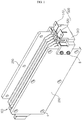
- FIG. 1 is a perspective view showing a battery module according to an embodiment of the present disclosure
- FIG. 2 is a perspective view showing a cell stack employed in the present disclosure
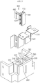
- FIG. 3 is an exploded perspective view showing a cartridge and a short-circuit unit employed in the present disclosure.
- the battery module may include a cell stack 100, a pair of end plates 200, a cartridge 300, a short-circuit unit 400 and a bus bar 500.
- the cell stack 100 includes at least two battery cells 110, and the plurality of battery cells 110 are stacked so that their broad surfaces face each other.
- the battery cell 110 is a pouch-type cell and may be configured so that an electrode assembly prepared by laminating a positive electrode plate, a separator and a negative electrode plate at least once is accommodated in a pouch case made of a pouch film, and rim regions of upper and lower pouch cases are sealed by thermal fusing.
- a pair of electrode leads 111, 112 are respectively connected to uncoated portions of the positive electrode plate and the negative electrode plate of the electrode assembly and are drawn out through the sealing region of the pouch case.
- the pair of electrode leads 111, 112 have different polarities, and the pair of electrode leads 111, 112 may extend in opposite directions.
- the battery cells 110 of the cell stack 100 may be arranged such that neighboring electrode leads have polarities opposite to each other. In this case, the battery cells 110 may be connected in series with each other.
- a pair of battery cells 110 disposed at the outermost side of the cell stack 100 respectively include electrode leads 111, 112 extending in the same direction and having different polarities.
- the electrode lead 111 provided in the battery cell 110 disposed at one outermost side of the cell stack 100 and extending toward the cartridge 300 and the electrode lead 112 provided in the battery cell 110 disposed at the other outermost side of the cell stack 100 and extending toward the cartridge 300 have different polarities.
- the electrode leads 111, 112 having different polarities may be in contact to each other to form a single lead aggregate 113.
- the electrode leads 111, 112 and the lead aggregate 113 are inserted and fixed in accommodation grooves formed in the cartridge 300 as described above, respectively, and this will be described in detail later.
- the pair of end plates 200 are disposed at both sides of the cell stack 100 to cover broad surfaces of the battery cells 110 disposed at the outermost sides.
- the pair of end plates 200 may be fastened to each other through a plurality of coupling holes H formed in peripheral regions thereof to fix and press the cell stack 100.
- the pair of end plates 200 may be fastened through the coupling holes H by applying various known fastening structures such as a bolting assembly or a bolt and nut fastening structure.
- the cartridge 300 is positioned at one side of the cell stack 100, in a direction along which the electrode leads 111, 112 and the lead aggregate 113 provided at the cell stack 100 are extended, so that one side of the cartridge 300 is fixed to one end plate 200 and the other side thereof is fixed to the other end plate 200.
- the cartridge 300 and the end plates 200 may be fixed using a bolt B.
- the cartridge 300 has an accommodation space 310 with a shape corresponding to the short-circuit unit 400, explained later, and also has a support portion 320 formed so that a stopper 440 of the short-circuit unit 400 may be caught and fixed.
- the cartridge 300 includes a first accommodation groove 330, a second accommodation groove 340 and a third accommodation groove 350 in which bus bars 510, 520, the lead aggregate 113 and the electrode leads 111, 112 are inserted and fixed, respectively.
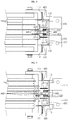
- FIG. 4 is a partial plane view showing the battery module according to an embodiment of the present disclosure, to illustrate a state before swelling occurs
- FIG. 5 is a partial plane view showing the battery module according to an embodiment of the present disclosure, to illustrate a state after swelling occurs.
- the short-circuit unit 400 is a component for electrically connecting the first bus bar 510 and the second bus bar 520 by using the expanding force of the battery cells 110 caused by swelling, so that a short circuit is generated.
- the short-circuit unit 400 may include a slide bar 410, an elastic member 420, a short-circuit terminal 430, and a pair of stoppers 440.
- the slide bar 410 is disposed in the accommodation space 310 of the cartridge 300 and moves from the battery cell 110 toward the bus bars 510, 520 when an expanding force is applied to the short-circuit unit 400 due to swelling.
- the slide bar 410 may be moved toward the bus bars 510, 520 by the force generated when the elastic member 420 such as a spring is compressed and then restored.
- the slide short-circuit unit 400 includes a short-circuit terminal 430 formed at one side end of the slide bar 410 and made of a conductive material.
- the short-circuit unit 400 includes the stopper 440 formed at one side end of the slide bar 410 so that the elastic member 420 may maintain a compressed state.
- the stopper 440 has, for example, a hook shape and may be caught by the support portion 320 of the cartridge 300.
- the stopper 440 keeps caught by the support portion 320, and thus the elastic member 420 stores the elastic energy in a compressed state.
- the short-circuit unit 400 if swelling occurs in the battery cells 110 to apply an expanding force of the battery cell 110 to the stopper 440, the caught and fixed state between the stopper 440 and the support portion 320 is released, and the slide bar 410 is moved toward the bus bars 510, 520 due to the restoration force of the elastic member 420 to electrically connect the pair of bus bars 510, 520 having different polarities to each other, thereby generating a short circuit.
- bus bar 500 employed at the present disclosure will be described in detail with reference to FIG. 6 along with FIGS. 3 to 5 .
- FIG. 6 is a perspective view showing a bus bar employed at the battery module according to an embodiment of the present disclosure.
- the bus bars 510, 520 employed at the present disclosure are accommodated and fixed in the first accommodation groove 330 formed in the cartridge 300, and their one ends are in contact with the electrode leads 111, 112 of the battery cells 110 disposed at the outermost sides of the cell stack 100 inside the third accommodation groove 350 of the cartridge 300.
- the pair of bus bars 510, 520 may be electrically connected to the cell stack 100 to have a first polarity and a second polarity opposite to the first polarity, respectively, and function as an external terminal of the battery module. Accordingly, the pair of bus bars 510, 520 may be respectively connected to a positive electrode and a negative electrode of an external device such as charging device or an electronic device driven by an electric energy to supply or receive a charging current.
- an external device such as charging device or an electronic device driven by an electric energy to supply or receive a charging current.
- At least one of the pair of bus bars 510, 520 may include breaking portions 511, 521 to break quickly and thus entirely block the current flow when overcurrent is generated due to a short circuit.
- the breaking portions 511, 521 may be shaped to have a smaller cross-sectional area becomes as compared with the peripheral regions by forming a notch thereto.
- the breaking portions 511, 521 may be prepared without any limitation as long as they may function as a fuse, for example by applying a metal with a lower melting point than the peripheral regions, in addition to the notch.
- FIG. 7 is a circuit diagram showing a state before a short circuit occurs at the battery module according to an embodiment of the present disclosure
- FIG. 8 is a circuit diagram showing a state after a short circuit occurs at the battery module according to an embodiment of the present disclosure
- FIG. 9 is a circuit diagram showing a state where the bus bar is broken due to a short circuit generated at the battery module according to an embodiment of the present disclosure.
- the short-circuit unit 400 may receive an expanding force of the battery cell 110 to electrically connect the first bus bar 510 and the second bus bar 520 so that a short circuit is generated on the circuit, and thus an abnormal high current may flow on the circuit.
- the breaking portion 511, 521 formed in at least one of the bus bars is broken due to heat generation caused by the high current, thereby blocking a current flow supplied from an external voltage source to the battery module or a current flow supplied from the battery module to an external electronic device. In this way, it is possible to prevent the battery module from being exploded or ignited in advance.
- a battery pack according to the present disclosure includes at least one battery module as described above. Also, in addition to the battery module according to an embodiment of the present disclosure, the battery pack may further include a case for accommodating the battery module, and various devices for controlling charge/discharge of the battery module such as a battery management system (BMS), a current sensor and a fuse.
- BMS battery management system
- the battery pack may include the first bus bar, the second bus bar, the short-circuit unit and the cartridge at each battery module provided at the battery pack to cut off the power supplied from the external voltage source by fracturing the first bus bar when the battery cell abnormally expands, so that overcharge is prevented for each battery module.
- the battery module according to the present disclosure may be applied to a vehicle such as an electric vehicle and a hybrid vehicle. That is, the vehicle according to the present disclosure may include the battery module of the present disclosure.
Landscapes
- Engineering & Computer Science (AREA)
- Chemical & Material Sciences (AREA)
- General Chemical & Material Sciences (AREA)
- Electrochemistry (AREA)
- Chemical Kinetics & Catalysis (AREA)
- Mechanical Engineering (AREA)
- Transportation (AREA)
- Life Sciences & Earth Sciences (AREA)
- Power Engineering (AREA)
- Sustainable Energy (AREA)
- Sustainable Development (AREA)
- Combustion & Propulsion (AREA)
- Battery Mounting, Suspending (AREA)
- Connection Of Batteries Or Terminals (AREA)
Applications Claiming Priority (2)
| Application Number | Priority Date | Filing Date | Title |
|---|---|---|---|
| KR1020170085993A KR102201342B1 (ko) | 2017-07-06 | 2017-07-06 | 배터리 모듈과 이를 포함하는 배터리 팩 및 자동차 |
| PCT/KR2018/007594 WO2019009625A1 (fr) | 2017-07-06 | 2018-07-04 | Module de batterie et bloc-batterie, et véhicule les comprenant |
Publications (3)
| Publication Number | Publication Date |
|---|---|
| EP3512008A1 true EP3512008A1 (fr) | 2019-07-17 |
| EP3512008A4 EP3512008A4 (fr) | 2019-10-02 |
| EP3512008B1 EP3512008B1 (fr) | 2023-01-11 |
Family
ID=64951061
Family Applications (1)
| Application Number | Title | Priority Date | Filing Date |
|---|---|---|---|
| EP18828081.2A Active EP3512008B1 (fr) | 2017-07-06 | 2018-07-04 | Module de batterie et bloc-batterie, et véhicule les comprenant |
Country Status (6)
| Country | Link |
|---|---|
| US (1) | US11046206B2 (fr) |
| EP (1) | EP3512008B1 (fr) |
| JP (1) | JP6780100B2 (fr) |
| KR (1) | KR102201342B1 (fr) |
| CN (1) | CN109844996B (fr) |
| WO (1) | WO2019009625A1 (fr) |
Cited By (1)
| Publication number | Priority date | Publication date | Assignee | Title |
|---|---|---|---|---|
| EP3540818A4 (fr) * | 2017-06-27 | 2020-01-15 | LG Chem, Ltd. | Module de batterie, et bloc-batterie et véhicule comprenant ledit module |
Families Citing this family (12)
| Publication number | Priority date | Publication date | Assignee | Title |
|---|---|---|---|---|
| KR102327877B1 (ko) * | 2019-01-23 | 2021-11-18 | 주식회사 와이제이테크놀로지 | 에너지저장시스템의 열폭주 방지장치 |
| CN110299574B (zh) * | 2019-05-21 | 2021-11-12 | 重庆交通大学 | 电池过充保护装置 |
| KR102464824B1 (ko) * | 2019-06-25 | 2022-11-07 | 주식회사 엘지에너지솔루션 | 전지 모듈 및 이를 포함하는 전지 팩 |
| KR102583650B1 (ko) * | 2019-07-01 | 2023-09-26 | 주식회사 엘지에너지솔루션 | 전지 모듈 및 이를 포함하는 전지팩 |
| KR20210064844A (ko) * | 2019-11-26 | 2021-06-03 | 주식회사 엘지에너지솔루션 | 전지 모듈 및 이를 포함하는 전지 팩 |
| CN111477800A (zh) * | 2020-04-30 | 2020-07-31 | 昆山宝创新能源科技有限公司 | 电池模块、电池包和车辆 |
| CN111477828A (zh) * | 2020-04-30 | 2020-07-31 | 昆山宝创新能源科技有限公司 | 电池模块及具有其的电池模组和汽车 |
| PL4044353T3 (pl) * | 2021-02-11 | 2023-10-02 | Samsung Sdi Co., Ltd. | Zestaw montażowy do montażu ramy nośnej stosu bloków ogniw baterii |
| CN113097665A (zh) * | 2021-03-30 | 2021-07-09 | 东莞新能安科技有限公司 | 电池模组及用电装置 |
| CN114374060B (zh) * | 2022-03-22 | 2022-06-14 | 深圳市青之鸟科技有限公司 | 一种应用于植保无人机的电池组 |
| CN114614202A (zh) * | 2022-03-29 | 2022-06-10 | 东莞新能安科技有限公司 | 电池包及用电设备 |
| KR20240054010A (ko) * | 2022-10-18 | 2024-04-25 | 주식회사 엘지에너지솔루션 | 통전 차단부를 구비한 배터리 팩 |
Family Cites Families (38)
| Publication number | Priority date | Publication date | Assignee | Title |
|---|---|---|---|---|
| JPH10294097A (ja) * | 1997-02-24 | 1998-11-04 | Mitsubishi Electric Corp | 薄型電池 |
| US5800937A (en) | 1997-05-02 | 1998-09-01 | Motorola, Inc. | Current interrupt device for secondary batteries |
| WO2005114810A1 (fr) * | 2004-05-17 | 2005-12-01 | Railpower Technologies Corp. | Dérivation automatique de shunt de cellule de batterie |
| KR100579377B1 (ko) * | 2004-10-28 | 2006-05-12 | 삼성에스디아이 주식회사 | 이차 전지 |
| BRPI0519197A2 (pt) * | 2004-12-23 | 2008-12-30 | Siemens Ag | processo e dispositivo para a operaÇço segura de um aparelho de comutaÇço |
| KR101046192B1 (ko) | 2007-10-30 | 2011-07-05 | 에스케이이노베이션 주식회사 | 2차 전지용 과충전 안전장치 |
| WO2009066880A2 (fr) * | 2007-11-21 | 2009-05-28 | Lg Chem, Ltd. | Module de batterie à sécurité améliorée et bloc batterie de taille moyenne ou grande le contenant |
| JP5329558B2 (ja) * | 2007-11-23 | 2013-10-30 | エルジー・ケム・リミテッド | 優れた生産性及び構造的安定性を与える二次バッテリーパック |
| KR101128423B1 (ko) * | 2008-04-28 | 2012-03-23 | 에스케이이노베이션 주식회사 | 전기자동차용 2차 전지의 안전 스위치 및 이를 이용한전기자동차용 2차 전지의 충방전 시스템 |
| KR101041153B1 (ko) * | 2009-03-04 | 2011-06-13 | 에스비리모티브 주식회사 | 이차전지 및 그 모듈 |
| US8323813B2 (en) * | 2009-05-14 | 2012-12-04 | Sb Limotive Co., Ltd. | Rechargeable battery including an extensible member |
| JP5355281B2 (ja) * | 2009-07-30 | 2013-11-27 | 日清紡ホールディングス株式会社 | 電気二重層キャパシタ |
| KR101072955B1 (ko) * | 2009-08-14 | 2011-10-12 | 에스비리모티브 주식회사 | 전지 모듈 |
| US8877361B2 (en) * | 2009-09-01 | 2014-11-04 | Samsung Sdi Co., Ltd. | Rechargeable battery |
| KR101281744B1 (ko) * | 2010-11-18 | 2013-07-04 | 주식회사 엘지화학 | 안전성의 향상을 위한 부재를 전지셀들 사이에 포함하고 있는 전지모듈 |
| KR101546545B1 (ko) | 2010-12-09 | 2015-08-24 | 주식회사 엘지화학 | 파우치형 리튬이차전지 |
| CN102738434B (zh) * | 2011-03-31 | 2014-03-05 | 松下蓄电池(沈阳)有限公司 | 铅蓄电池 |
| KR101359310B1 (ko) | 2011-07-25 | 2014-02-07 | 주식회사 엘지화학 | 안전성이 향상된 전지팩 |
| KR101294168B1 (ko) | 2011-09-26 | 2013-08-08 | 기아자동차주식회사 | 배터리의 과충전 방지장치 |
| EP2662913B1 (fr) | 2011-11-28 | 2016-04-20 | LG Chem, Ltd. | Module de batterie et barre omnibus appliquée au module de batterie |
| KR101404712B1 (ko) * | 2012-01-26 | 2014-06-09 | 주식회사 엘지화학 | 안전성이 향상된 전지팩 |
| EP2827408B1 (fr) | 2012-03-15 | 2017-04-19 | Kabushiki Kaisha Toshiba | Batterie lithium-ion rechargeable |
| JP5727090B2 (ja) * | 2012-03-15 | 2015-06-03 | 株式会社東芝 | リチウムイオン二次電池 |
| KR101965398B1 (ko) * | 2012-10-26 | 2019-04-03 | 에스케이이노베이션 주식회사 | 리튬이차전지의 셀 탭 커팅장치 및 이를 갖는 전지팩 |
| KR101389227B1 (ko) | 2012-12-27 | 2014-04-29 | 에이치엘그린파워 주식회사 | 과충전 방지 수단을 가지는 리튬이온 배터리 모듈 |
| KR102018693B1 (ko) * | 2013-02-06 | 2019-09-05 | 삼성에스디아이 주식회사 | 이차 전지 팩 |
| KR101449306B1 (ko) * | 2013-06-28 | 2014-10-08 | 현대자동차주식회사 | 배터리 과충전 보호장치 |
| KR101500101B1 (ko) | 2013-07-10 | 2015-03-06 | 현대자동차주식회사 | 배터리 과충전 방지장치 |
| US9722231B2 (en) | 2013-09-06 | 2017-08-01 | Johnson Controls Technology Company | Bladed fuse connectors for use in a vehicle battery module |
| KR20150053597A (ko) * | 2013-11-08 | 2015-05-18 | 삼성에스디아이 주식회사 | 배터리 모듈 |
| KR102046125B1 (ko) * | 2013-11-13 | 2019-11-18 | 에스케이이노베이션 주식회사 | 착탈식 전압센싱모듈 및 이를 구비한 배터리장치 |
| KR101846418B1 (ko) * | 2013-12-17 | 2018-04-06 | 지멘스 악티엔게젤샤프트 | Hvdc 컨버터를 위한 보호 전자 모듈 |
| KR20160026469A (ko) * | 2014-09-01 | 2016-03-09 | 에스케이이노베이션 주식회사 | 저전압 센싱모듈 일체형 버스바를 구비한 배터리모듈 |
| KR20160030688A (ko) | 2014-09-11 | 2016-03-21 | 주식회사 루트제이드 | 과전류 차단수단이 구비된 이차전지 |
| KR102032503B1 (ko) * | 2015-11-05 | 2019-10-15 | 주식회사 엘지화학 | 배터리 모듈, 이러한 배터리 모듈을 포함하는 배터리 팩 및 이러한 배터리 팩을 포함하는 자동차 |
| CN205790140U (zh) * | 2016-07-11 | 2016-12-07 | 宁德时代新能源科技股份有限公司 | 动力电池模组的侧板及动力电池模组 |
| KR102201344B1 (ko) * | 2017-05-26 | 2021-01-08 | 주식회사 엘지화학 | 배터리 모듈과 이를 포함하는 배터리 팩 및 자동차 |
| KR102163656B1 (ko) * | 2017-06-27 | 2020-10-08 | 주식회사 엘지화학 | 배터리 모듈과 이를 포함하는 배터리 팩 및 자동차 |
-
2017
- 2017-07-06 KR KR1020170085993A patent/KR102201342B1/ko active IP Right Grant
-
2018
- 2018-07-04 US US16/332,836 patent/US11046206B2/en active Active
- 2018-07-04 EP EP18828081.2A patent/EP3512008B1/fr active Active
- 2018-07-04 WO PCT/KR2018/007594 patent/WO2019009625A1/fr unknown
- 2018-07-04 CN CN201880004012.8A patent/CN109844996B/zh active Active
- 2018-07-04 JP JP2019517888A patent/JP6780100B2/ja active Active
Cited By (2)
| Publication number | Priority date | Publication date | Assignee | Title |
|---|---|---|---|---|
| EP3540818A4 (fr) * | 2017-06-27 | 2020-01-15 | LG Chem, Ltd. | Module de batterie, et bloc-batterie et véhicule comprenant ledit module |
| US10892468B2 (en) | 2017-06-27 | 2021-01-12 | Lg Chem, Ltd. | Battery module with short-circuit unit, and battery pack and vehicle including the same |
Also Published As
| Publication number | Publication date |
|---|---|
| US20190366875A1 (en) | 2019-12-05 |
| KR20190005403A (ko) | 2019-01-16 |
| EP3512008A4 (fr) | 2019-10-02 |
| US11046206B2 (en) | 2021-06-29 |
| CN109844996B (zh) | 2021-11-09 |
| EP3512008B1 (fr) | 2023-01-11 |
| KR102201342B1 (ko) | 2021-01-08 |
| JP2019530186A (ja) | 2019-10-17 |
| CN109844996A (zh) | 2019-06-04 |
| WO2019009625A1 (fr) | 2019-01-10 |
| JP6780100B2 (ja) | 2020-11-04 |
Similar Documents
| Publication | Publication Date | Title |
|---|---|---|
| US11046206B2 (en) | Battery module with short-circuit unit, and battery pack and vehicle including the same | |
| KR100881641B1 (ko) | 안전 시스템을 구비한 중대형 전지팩 | |
| KR100914839B1 (ko) | 안전성이 향상된 전지모듈 및 이를 포함하는 중대형 전지팩 | |
| JP5575761B2 (ja) | 安全性を改良した中型又は大型バッテリーパック | |
| US10892468B2 (en) | Battery module with short-circuit unit, and battery pack and vehicle including the same | |
| JP7034405B2 (ja) | バッテリーモジュール、それを含むバッテリーパック及び自動車 | |
| EP3540823B1 (fr) | Module de batterie et bloc-batterie et véhicule les comprenant | |
| KR102249457B1 (ko) | 배터리 모듈과 이를 포함하는 배터리 팩 및 자동차 | |
| US11881597B2 (en) | Battery module with improved safety, battery pack comprising battery module, and vehicle comprising battery pack | |
| KR102267056B1 (ko) | 배터리 모듈과 이를 포함하는 배터리 팩 및 자동차 | |
| KR102308168B1 (ko) | 배터리 모듈과 이를 포함하는 배터리 팩 및 자동차 |
Legal Events
| Date | Code | Title | Description |
|---|---|---|---|
| STAA | Information on the status of an ep patent application or granted ep patent |
Free format text: STATUS: THE INTERNATIONAL PUBLICATION HAS BEEN MADE |
|
| PUAI | Public reference made under article 153(3) epc to a published international application that has entered the european phase |
Free format text: ORIGINAL CODE: 0009012 |
|
| STAA | Information on the status of an ep patent application or granted ep patent |
Free format text: STATUS: REQUEST FOR EXAMINATION WAS MADE |
|
| 17P | Request for examination filed |
Effective date: 20190410 |
|
| AK | Designated contracting states |
Kind code of ref document: A1 Designated state(s): AL AT BE BG CH CY CZ DE DK EE ES FI FR GB GR HR HU IE IS IT LI LT LU LV MC MK MT NL NO PL PT RO RS SE SI SK SM TR |
|
| AX | Request for extension of the european patent |
Extension state: BA ME |
|
| A4 | Supplementary search report drawn up and despatched |
Effective date: 20190902 |
|
| RIC1 | Information provided on ipc code assigned before grant |
Ipc: H01M 2/10 20060101ALI20190827BHEP Ipc: B60K 6/28 20071001ALI20190827BHEP Ipc: H01M 2/30 20060101ALI20190827BHEP Ipc: H01M 2/20 20060101ALI20190827BHEP Ipc: H01M 2/34 20060101AFI20190827BHEP |
|
| STAA | Information on the status of an ep patent application or granted ep patent |
Free format text: STATUS: EXAMINATION IS IN PROGRESS |
|
| 17Q | First examination report despatched |
Effective date: 20200416 |
|
| STAA | Information on the status of an ep patent application or granted ep patent |
Free format text: STATUS: EXAMINATION IS IN PROGRESS |
|
| DAV | Request for validation of the european patent (deleted) | ||
| DAX | Request for extension of the european patent (deleted) | ||
| RAP1 | Party data changed (applicant data changed or rights of an application transferred) |
Owner name: LG ENERGY SOLUTION LTD. |
|
| RAP3 | Party data changed (applicant data changed or rights of an application transferred) |
Owner name: LG ENERGY SOLUTION, LTD. |
|
| REG | Reference to a national code |
Ref country code: DE Ref legal event code: R079 Ref document number: 602018045371 Country of ref document: DE Free format text: PREVIOUS MAIN CLASS: H01M0002340000 Ipc: B60K0006280000 |
|
| RIC1 | Information provided on ipc code assigned before grant |
Ipc: H01M 50/553 20210101ALN20220823BHEP Ipc: H01M 50/548 20210101ALN20220823BHEP Ipc: H01M 50/178 20210101ALN20220823BHEP Ipc: H01M 50/578 20210101ALI20220823BHEP Ipc: H01M 50/51 20210101ALI20220823BHEP Ipc: H01M 50/507 20210101ALI20220823BHEP Ipc: H01M 50/211 20210101ALI20220823BHEP Ipc: B60K 6/28 20071001AFI20220823BHEP |
|
| GRAP | Despatch of communication of intention to grant a patent |
Free format text: ORIGINAL CODE: EPIDOSNIGR1 |
|
| STAA | Information on the status of an ep patent application or granted ep patent |
Free format text: STATUS: GRANT OF PATENT IS INTENDED |
|
| INTG | Intention to grant announced |
Effective date: 20221010 |
|
| GRAS | Grant fee paid |
Free format text: ORIGINAL CODE: EPIDOSNIGR3 |
|
| GRAA | (expected) grant |
Free format text: ORIGINAL CODE: 0009210 |
|
| STAA | Information on the status of an ep patent application or granted ep patent |
Free format text: STATUS: THE PATENT HAS BEEN GRANTED |
|
| AK | Designated contracting states |
Kind code of ref document: B1 Designated state(s): AL AT BE BG CH CY CZ DE DK EE ES FI FR GB GR HR HU IE IS IT LI LT LU LV MC MK MT NL NO PL PT RO RS SE SI SK SM TR |
|
| REG | Reference to a national code |
Ref country code: GB Ref legal event code: FG4D |
|
| REG | Reference to a national code |
Ref country code: CH Ref legal event code: EP |
|
| REG | Reference to a national code |
Ref country code: DE Ref legal event code: R096 Ref document number: 602018045371 Country of ref document: DE |
|
| REG | Reference to a national code |
Ref country code: IE Ref legal event code: FG4D |
|
| REG | Reference to a national code |
Ref country code: AT Ref legal event code: REF Ref document number: 1543217 Country of ref document: AT Kind code of ref document: T Effective date: 20230215 |
|
| REG | Reference to a national code |
Ref country code: LT Ref legal event code: MG9D |
|
| REG | Reference to a national code |
Ref country code: NL Ref legal event code: MP Effective date: 20230111 |
|
| REG | Reference to a national code |
Ref country code: AT Ref legal event code: MK05 Ref document number: 1543217 Country of ref document: AT Kind code of ref document: T Effective date: 20230111 |
|
| P01 | Opt-out of the competence of the unified patent court (upc) registered |
Effective date: 20230512 |
|
| PG25 | Lapsed in a contracting state [announced via postgrant information from national office to epo] |
Ref country code: NL Free format text: LAPSE BECAUSE OF FAILURE TO SUBMIT A TRANSLATION OF THE DESCRIPTION OR TO PAY THE FEE WITHIN THE PRESCRIBED TIME-LIMIT Effective date: 20230111 |
|
| PG25 | Lapsed in a contracting state [announced via postgrant information from national office to epo] |
Ref country code: RS Free format text: LAPSE BECAUSE OF FAILURE TO SUBMIT A TRANSLATION OF THE DESCRIPTION OR TO PAY THE FEE WITHIN THE PRESCRIBED TIME-LIMIT Effective date: 20230111 Ref country code: PT Free format text: LAPSE BECAUSE OF FAILURE TO SUBMIT A TRANSLATION OF THE DESCRIPTION OR TO PAY THE FEE WITHIN THE PRESCRIBED TIME-LIMIT Effective date: 20230511 Ref country code: NO Free format text: LAPSE BECAUSE OF FAILURE TO SUBMIT A TRANSLATION OF THE DESCRIPTION OR TO PAY THE FEE WITHIN THE PRESCRIBED TIME-LIMIT Effective date: 20230411 Ref country code: LV Free format text: LAPSE BECAUSE OF FAILURE TO SUBMIT A TRANSLATION OF THE DESCRIPTION OR TO PAY THE FEE WITHIN THE PRESCRIBED TIME-LIMIT Effective date: 20230111 Ref country code: LT Free format text: LAPSE BECAUSE OF FAILURE TO SUBMIT A TRANSLATION OF THE DESCRIPTION OR TO PAY THE FEE WITHIN THE PRESCRIBED TIME-LIMIT Effective date: 20230111 Ref country code: HR Free format text: LAPSE BECAUSE OF FAILURE TO SUBMIT A TRANSLATION OF THE DESCRIPTION OR TO PAY THE FEE WITHIN THE PRESCRIBED TIME-LIMIT Effective date: 20230111 Ref country code: ES Free format text: LAPSE BECAUSE OF FAILURE TO SUBMIT A TRANSLATION OF THE DESCRIPTION OR TO PAY THE FEE WITHIN THE PRESCRIBED TIME-LIMIT Effective date: 20230111 Ref country code: AT Free format text: LAPSE BECAUSE OF FAILURE TO SUBMIT A TRANSLATION OF THE DESCRIPTION OR TO PAY THE FEE WITHIN THE PRESCRIBED TIME-LIMIT Effective date: 20230111 |
|
| PGFP | Annual fee paid to national office [announced via postgrant information from national office to epo] |
Ref country code: FR Payment date: 20230621 Year of fee payment: 6 |
|
| PG25 | Lapsed in a contracting state [announced via postgrant information from national office to epo] |
Ref country code: SE Free format text: LAPSE BECAUSE OF FAILURE TO SUBMIT A TRANSLATION OF THE DESCRIPTION OR TO PAY THE FEE WITHIN THE PRESCRIBED TIME-LIMIT Effective date: 20230111 Ref country code: PL Free format text: LAPSE BECAUSE OF FAILURE TO SUBMIT A TRANSLATION OF THE DESCRIPTION OR TO PAY THE FEE WITHIN THE PRESCRIBED TIME-LIMIT Effective date: 20230111 Ref country code: IS Free format text: LAPSE BECAUSE OF FAILURE TO SUBMIT A TRANSLATION OF THE DESCRIPTION OR TO PAY THE FEE WITHIN THE PRESCRIBED TIME-LIMIT Effective date: 20230511 Ref country code: GR Free format text: LAPSE BECAUSE OF FAILURE TO SUBMIT A TRANSLATION OF THE DESCRIPTION OR TO PAY THE FEE WITHIN THE PRESCRIBED TIME-LIMIT Effective date: 20230412 Ref country code: FI Free format text: LAPSE BECAUSE OF FAILURE TO SUBMIT A TRANSLATION OF THE DESCRIPTION OR TO PAY THE FEE WITHIN THE PRESCRIBED TIME-LIMIT Effective date: 20230111 |
|
| REG | Reference to a national code |
Ref country code: DE Ref legal event code: R097 Ref document number: 602018045371 Country of ref document: DE |
|
| PG25 | Lapsed in a contracting state [announced via postgrant information from national office to epo] |
Ref country code: SM Free format text: LAPSE BECAUSE OF FAILURE TO SUBMIT A TRANSLATION OF THE DESCRIPTION OR TO PAY THE FEE WITHIN THE PRESCRIBED TIME-LIMIT Effective date: 20230111 Ref country code: RO Free format text: LAPSE BECAUSE OF FAILURE TO SUBMIT A TRANSLATION OF THE DESCRIPTION OR TO PAY THE FEE WITHIN THE PRESCRIBED TIME-LIMIT Effective date: 20230111 Ref country code: EE Free format text: LAPSE BECAUSE OF FAILURE TO SUBMIT A TRANSLATION OF THE DESCRIPTION OR TO PAY THE FEE WITHIN THE PRESCRIBED TIME-LIMIT Effective date: 20230111 Ref country code: DK Free format text: LAPSE BECAUSE OF FAILURE TO SUBMIT A TRANSLATION OF THE DESCRIPTION OR TO PAY THE FEE WITHIN THE PRESCRIBED TIME-LIMIT Effective date: 20230111 Ref country code: CZ Free format text: LAPSE BECAUSE OF FAILURE TO SUBMIT A TRANSLATION OF THE DESCRIPTION OR TO PAY THE FEE WITHIN THE PRESCRIBED TIME-LIMIT Effective date: 20230111 |
|
| PGFP | Annual fee paid to national office [announced via postgrant information from national office to epo] |
Ref country code: GB Payment date: 20230620 Year of fee payment: 6 |
|
| PLBE | No opposition filed within time limit |
Free format text: ORIGINAL CODE: 0009261 |
|
| STAA | Information on the status of an ep patent application or granted ep patent |
Free format text: STATUS: NO OPPOSITION FILED WITHIN TIME LIMIT |
|
| PG25 | Lapsed in a contracting state [announced via postgrant information from national office to epo] |
Ref country code: SK Free format text: LAPSE BECAUSE OF FAILURE TO SUBMIT A TRANSLATION OF THE DESCRIPTION OR TO PAY THE FEE WITHIN THE PRESCRIBED TIME-LIMIT Effective date: 20230111 |
|
| PGFP | Annual fee paid to national office [announced via postgrant information from national office to epo] |
Ref country code: DE Payment date: 20230620 Year of fee payment: 6 |
|
| 26N | No opposition filed |
Effective date: 20231012 |
|
| PG25 | Lapsed in a contracting state [announced via postgrant information from national office to epo] |
Ref country code: SI Free format text: LAPSE BECAUSE OF FAILURE TO SUBMIT A TRANSLATION OF THE DESCRIPTION OR TO PAY THE FEE WITHIN THE PRESCRIBED TIME-LIMIT Effective date: 20230111 |
|
| PG25 | Lapsed in a contracting state [announced via postgrant information from national office to epo] |
Ref country code: MC Free format text: LAPSE BECAUSE OF FAILURE TO SUBMIT A TRANSLATION OF THE DESCRIPTION OR TO PAY THE FEE WITHIN THE PRESCRIBED TIME-LIMIT Effective date: 20230111 |
|
| PG25 | Lapsed in a contracting state [announced via postgrant information from national office to epo] |
Ref country code: MC Free format text: LAPSE BECAUSE OF FAILURE TO SUBMIT A TRANSLATION OF THE DESCRIPTION OR TO PAY THE FEE WITHIN THE PRESCRIBED TIME-LIMIT Effective date: 20230111 |
|
| REG | Reference to a national code |
Ref country code: CH Ref legal event code: PL |
|
| REG | Reference to a national code |
Ref country code: BE Ref legal event code: MM Effective date: 20230731 |
|
| PG25 | Lapsed in a contracting state [announced via postgrant information from national office to epo] |
Ref country code: LU Free format text: LAPSE BECAUSE OF NON-PAYMENT OF DUE FEES Effective date: 20230704 |
|
| PG25 | Lapsed in a contracting state [announced via postgrant information from national office to epo] |
Ref country code: LU Free format text: LAPSE BECAUSE OF NON-PAYMENT OF DUE FEES Effective date: 20230704 |
|
| REG | Reference to a national code |
Ref country code: IE Ref legal event code: MM4A |
|
| PG25 | Lapsed in a contracting state [announced via postgrant information from national office to epo] |
Ref country code: CH Free format text: LAPSE BECAUSE OF NON-PAYMENT OF DUE FEES Effective date: 20230731 |