EP3540823B1 - Module de batterie et bloc-batterie et véhicule les comprenant - Google Patents
Module de batterie et bloc-batterie et véhicule les comprenant Download PDFInfo
- Publication number
- EP3540823B1 EP3540823B1 EP18817230.8A EP18817230A EP3540823B1 EP 3540823 B1 EP3540823 B1 EP 3540823B1 EP 18817230 A EP18817230 A EP 18817230A EP 3540823 B1 EP3540823 B1 EP 3540823B1
- Authority
- EP
- European Patent Office
- Prior art keywords
- bus bar
- battery cell
- battery module
- short
- battery
- Prior art date
- Legal status (The legal status is an assumption and is not a legal conclusion. Google has not performed a legal analysis and makes no representation as to the accuracy of the status listed.)
- Active
Links
- 230000004308 accommodation Effects 0.000 claims description 8
- 239000004020 conductor Substances 0.000 claims description 3
- 238000005452 bending Methods 0.000 description 32
- 238000010586 diagram Methods 0.000 description 20
- WHXSMMKQMYFTQS-UHFFFAOYSA-N Lithium Chemical compound [Li] WHXSMMKQMYFTQS-UHFFFAOYSA-N 0.000 description 8
- 229910052744 lithium Inorganic materials 0.000 description 8
- PXHVJJICTQNCMI-UHFFFAOYSA-N Nickel Chemical compound [Ni] PXHVJJICTQNCMI-UHFFFAOYSA-N 0.000 description 5
- 230000001965 increasing effect Effects 0.000 description 5
- 238000007599 discharging Methods 0.000 description 3
- 239000007789 gas Substances 0.000 description 3
- 230000008961 swelling Effects 0.000 description 3
- 230000002159 abnormal effect Effects 0.000 description 2
- OJIJEKBXJYRIBZ-UHFFFAOYSA-N cadmium nickel Chemical compound [Ni].[Cd] OJIJEKBXJYRIBZ-UHFFFAOYSA-N 0.000 description 2
- 238000000354 decomposition reaction Methods 0.000 description 2
- 239000003792 electrolyte Substances 0.000 description 2
- 230000006870 function Effects 0.000 description 2
- 229910052751 metal Inorganic materials 0.000 description 2
- 239000002184 metal Substances 0.000 description 2
- 239000007773 negative electrode material Substances 0.000 description 2
- 229910052759 nickel Inorganic materials 0.000 description 2
- QELJHCBNGDEXLD-UHFFFAOYSA-N nickel zinc Chemical compound [Ni].[Zn] QELJHCBNGDEXLD-UHFFFAOYSA-N 0.000 description 2
- 239000007774 positive electrode material Substances 0.000 description 2
- 238000000926 separation method Methods 0.000 description 2
- OKTJSMMVPCPJKN-UHFFFAOYSA-N Carbon Chemical compound [C] OKTJSMMVPCPJKN-UHFFFAOYSA-N 0.000 description 1
- UFHFLCQGNIYNRP-UHFFFAOYSA-N Hydrogen Chemical compound [H][H] UFHFLCQGNIYNRP-UHFFFAOYSA-N 0.000 description 1
- HBBGRARXTFLTSG-UHFFFAOYSA-N Lithium ion Chemical compound [Li+] HBBGRARXTFLTSG-UHFFFAOYSA-N 0.000 description 1
- 239000011149 active material Substances 0.000 description 1
- 229910052782 aluminium Inorganic materials 0.000 description 1
- XAGFODPZIPBFFR-UHFFFAOYSA-N aluminium Chemical compound [Al] XAGFODPZIPBFFR-UHFFFAOYSA-N 0.000 description 1
- 229910052799 carbon Inorganic materials 0.000 description 1
- 239000003575 carbonaceous material Substances 0.000 description 1
- 230000008602 contraction Effects 0.000 description 1
- 230000000694 effects Effects 0.000 description 1
- 238000004146 energy storage Methods 0.000 description 1
- 238000005516 engineering process Methods 0.000 description 1
- 239000003344 environmental pollutant Substances 0.000 description 1
- 238000004880 explosion Methods 0.000 description 1
- 239000000446 fuel Substances 0.000 description 1
- 229910052739 hydrogen Inorganic materials 0.000 description 1
- 239000001257 hydrogen Substances 0.000 description 1
- 230000001939 inductive effect Effects 0.000 description 1
- 229910001416 lithium ion Inorganic materials 0.000 description 1
- 238000002844 melting Methods 0.000 description 1
- 230000008018 melting Effects 0.000 description 1
- 230000003446 memory effect Effects 0.000 description 1
- 238000000034 method Methods 0.000 description 1
- 229910000652 nickel hydride Inorganic materials 0.000 description 1
- 231100000719 pollutant Toxicity 0.000 description 1
- 229920000642 polymer Polymers 0.000 description 1
- 230000002250 progressing effect Effects 0.000 description 1
- 230000003252 repetitive effect Effects 0.000 description 1
- 238000013022 venting Methods 0.000 description 1
Images


Classifications
-
- H—ELECTRICITY
- H01—ELECTRIC ELEMENTS
- H01M—PROCESSES OR MEANS, e.g. BATTERIES, FOR THE DIRECT CONVERSION OF CHEMICAL ENERGY INTO ELECTRICAL ENERGY
- H01M50/00—Constructional details or processes of manufacture of the non-active parts of electrochemical cells other than fuel cells, e.g. hybrid cells
- H01M50/50—Current conducting connections for cells or batteries
- H01M50/572—Means for preventing undesired use or discharge
-
- F—MECHANICAL ENGINEERING; LIGHTING; HEATING; WEAPONS; BLASTING
- F16—ENGINEERING ELEMENTS AND UNITS; GENERAL MEASURES FOR PRODUCING AND MAINTAINING EFFECTIVE FUNCTIONING OF MACHINES OR INSTALLATIONS; THERMAL INSULATION IN GENERAL
- F16H—GEARING
- F16H19/00—Gearings comprising essentially only toothed gears or friction members and not capable of conveying indefinitely-continuing rotary motion
- F16H19/02—Gearings comprising essentially only toothed gears or friction members and not capable of conveying indefinitely-continuing rotary motion for interconverting rotary or oscillating motion and reciprocating motion
- F16H19/04—Gearings comprising essentially only toothed gears or friction members and not capable of conveying indefinitely-continuing rotary motion for interconverting rotary or oscillating motion and reciprocating motion comprising a rack
-
- H—ELECTRICITY
- H01—ELECTRIC ELEMENTS
- H01M—PROCESSES OR MEANS, e.g. BATTERIES, FOR THE DIRECT CONVERSION OF CHEMICAL ENERGY INTO ELECTRICAL ENERGY
- H01M10/00—Secondary cells; Manufacture thereof
- H01M10/42—Methods or arrangements for servicing or maintenance of secondary cells or secondary half-cells
- H01M10/4235—Safety or regulating additives or arrangements in electrodes, separators or electrolyte
-
- H—ELECTRICITY
- H01—ELECTRIC ELEMENTS
- H01M—PROCESSES OR MEANS, e.g. BATTERIES, FOR THE DIRECT CONVERSION OF CHEMICAL ENERGY INTO ELECTRICAL ENERGY
- H01M50/00—Constructional details or processes of manufacture of the non-active parts of electrochemical cells other than fuel cells, e.g. hybrid cells
- H01M50/20—Mountings; Secondary casings or frames; Racks, modules or packs; Suspension devices; Shock absorbers; Transport or carrying devices; Holders
- H01M50/204—Racks, modules or packs for multiple batteries or multiple cells
- H01M50/207—Racks, modules or packs for multiple batteries or multiple cells characterised by their shape
- H01M50/211—Racks, modules or packs for multiple batteries or multiple cells characterised by their shape adapted for pouch cells
-
- H—ELECTRICITY
- H01—ELECTRIC ELEMENTS
- H01M—PROCESSES OR MEANS, e.g. BATTERIES, FOR THE DIRECT CONVERSION OF CHEMICAL ENERGY INTO ELECTRICAL ENERGY
- H01M50/00—Constructional details or processes of manufacture of the non-active parts of electrochemical cells other than fuel cells, e.g. hybrid cells
- H01M50/50—Current conducting connections for cells or batteries
- H01M50/502—Interconnectors for connecting terminals of adjacent batteries; Interconnectors for connecting cells outside a battery casing
- H01M50/507—Interconnectors for connecting terminals of adjacent batteries; Interconnectors for connecting cells outside a battery casing comprising an arrangement of two or more busbars within a container structure, e.g. busbar modules
-
- H—ELECTRICITY
- H01—ELECTRIC ELEMENTS
- H01M—PROCESSES OR MEANS, e.g. BATTERIES, FOR THE DIRECT CONVERSION OF CHEMICAL ENERGY INTO ELECTRICAL ENERGY
- H01M50/00—Constructional details or processes of manufacture of the non-active parts of electrochemical cells other than fuel cells, e.g. hybrid cells
- H01M50/50—Current conducting connections for cells or batteries
- H01M50/572—Means for preventing undesired use or discharge
- H01M50/584—Means for preventing undesired use or discharge for preventing incorrect connections inside or outside the batteries
- H01M50/588—Means for preventing undesired use or discharge for preventing incorrect connections inside or outside the batteries outside the batteries, e.g. incorrect connections of terminals or busbars
-
- H—ELECTRICITY
- H01—ELECTRIC ELEMENTS
- H01M—PROCESSES OR MEANS, e.g. BATTERIES, FOR THE DIRECT CONVERSION OF CHEMICAL ENERGY INTO ELECTRICAL ENERGY
- H01M2200/00—Safety devices for primary or secondary batteries
-
- H—ELECTRICITY
- H01—ELECTRIC ELEMENTS
- H01M—PROCESSES OR MEANS, e.g. BATTERIES, FOR THE DIRECT CONVERSION OF CHEMICAL ENERGY INTO ELECTRICAL ENERGY
- H01M2200/00—Safety devices for primary or secondary batteries
- H01M2200/20—Pressure-sensitive devices
-
- H—ELECTRICITY
- H01—ELECTRIC ELEMENTS
- H01M—PROCESSES OR MEANS, e.g. BATTERIES, FOR THE DIRECT CONVERSION OF CHEMICAL ENERGY INTO ELECTRICAL ENERGY
- H01M2220/00—Batteries for particular applications
- H01M2220/20—Batteries in motive systems, e.g. vehicle, ship, plane
-
- Y—GENERAL TAGGING OF NEW TECHNOLOGICAL DEVELOPMENTS; GENERAL TAGGING OF CROSS-SECTIONAL TECHNOLOGIES SPANNING OVER SEVERAL SECTIONS OF THE IPC; TECHNICAL SUBJECTS COVERED BY FORMER USPC CROSS-REFERENCE ART COLLECTIONS [XRACs] AND DIGESTS
- Y02—TECHNOLOGIES OR APPLICATIONS FOR MITIGATION OR ADAPTATION AGAINST CLIMATE CHANGE
- Y02E—REDUCTION OF GREENHOUSE GAS [GHG] EMISSIONS, RELATED TO ENERGY GENERATION, TRANSMISSION OR DISTRIBUTION
- Y02E60/00—Enabling technologies; Technologies with a potential or indirect contribution to GHG emissions mitigation
- Y02E60/10—Energy storage using batteries
Definitions
- the present disclosure relates to a battery module, and a battery pack and a vehicle including the same, and more particularly, to a battery module having improved stability by preventing overcharge of the battery module, and a battery pack and a vehicle including the same.
- Secondary batteries commercially available at the present include nickel-cadmium batteries, nickel hydrogen batteries, nickel-zinc batteries, lithium secondary batteries and the like.
- the lithium secondary batteries are in the limelight since they have almost no memory effect compared to nickel-based secondary batteries and also have very low self-discharging rate and high energy density.
- the lithium secondary battery mainly uses lithium-based oxide and carbonaceous material as a positive electrode active material and a negative electrode active material, respectively.
- the lithium secondary battery includes an electrode assembly in which a positive electrode plate and a negative electrode plate respectively coated with a positive electrode active material and a negative electrode active material are disposed with a separator being interposed therebetween, and an exterior, namely a battery case, in which the electrode assembly is accommodated and sealed together with an electrolyte.
- a lithium secondary battery may be classified into a can-type secondary battery in which an electrode assembly is included in a metal can and a pouch-type secondary battery in which an electrode assembly is included in a pouch made of aluminum laminate sheets, depending on the shape of an exterior.
- the battery pack of the hybrid electric vehicle or electric vehicle includes a plurality of secondary batteries, and the plurality of secondary batteries are connected in series and in parallel to improve capacity and power.
- the secondary battery has excellent electrical characteristics, but in the abnormal operating conditions such as overcharge, overdischarge, exposure to high temperature and electrical short circuit, the decomposition reaction of an active material, an electrolyte and the like of the battery is caused to generate heat and gas, thereby resulting in a so-called swelling phenomenon where the secondary battery swells.
- the swelling phenomenon accelerates the decomposition reaction, which may cause explosion and ignition of the secondary battery due to thermal runaway.
- the secondary battery includes a safety system such as a protection circuit for cutting a current at overcharge, overdischarge or overcurrent, a positive temperature coefficient (PTC) element for cutting a current by greatly increasing resistance when temperature rises, a safety vent for cutting a current or venting a gas when pressure increases due to gas generation.
- a safety system such as a protection circuit for cutting a current at overcharge, overdischarge or overcurrent, a positive temperature coefficient (PTC) element for cutting a current by greatly increasing resistance when temperature rises, a safety vent for cutting a current or venting a gas when pressure increases due to gas generation.
- PTC positive temperature coefficient
- the secondary battery repeats expansion and contraction even when it is in a normal operating state, not in an abnormal operating state, and thus the current of the secondary battery may be cut even in a normal operation range, which may deteriorate the operation reliability.
- EP 2 284 929 A1 concerns a battery module including a plurality of rechargeable batteries including a case and terminals protruding outside of the case; a plurality of connecting members electrically connecting first terminals of neighboring rechargeable batteries; and a shorting member configured to generate a short circuit by connecting neighboring connecting members to each other.
- the shorting member comprises a shorting plate contactable with the neighboring connecting members for inducing the short circuit, and a driver coupled to the shorting plate and configured to move the shorting plate to contact the neighboring connecting members.
- the present disclosure is directed to providing a battery module, which may prevent overcharge by fracturing a fracturing portion formed at a first bus bar since a short-circuit unit moves toward a first bus bar and a second bus bar and comes into contact thereto by receiving an expansive force due to the volume increase of at least one of a first battery cell and a second battery cell to electrically connect the first bus bar and the second bus bar and thus cause a short circuit, and to providing a battery pack and a vehicle including the battery module.
- a battery module comprising: a first bus bar electrically connected to a first electrode lead of a first battery cell; a second bus bar electrically connected to a second electrode lead of a second battery cell; a short-circuit unit configured to move toward the first bus bar and the second bus bar by receiving an expansive force due to a volume increase of at least one of the first battery cell and the second battery cell so that the first bus bar and the second bus bar are electrically connected to generate a short circuit; and a cartridge configured to accommodate or support at least a portion of the first electrode lead, the second electrode lead, the first bus bar, the second bus bar and the short-circuit unit.
- the short-circuit unit includes: an elastic member having one end supported to an inner side of the cartridge and configured to provide an elastic force in a direction opposite to the expansive force; a slide bar having a short-circuit terminal provided at one end thereof to contact the other end of the elastic member and receive the elastic force from the elastic member, the slide bar having a rack gear formed along a surface of the other end thereof; and an expansive force transmitting unit having a pinion gear provided at one end thereof to engage with the rack gear and support the other end of the slide bar, the expansive force transmitting unit having the other end that is in contact with one end of each of the first battery cell and the second battery cell to receive the expansive force.
- the slide bar may receive only the elastic force so that the short-circuit terminal is spaced apart from the first battery cell and the second battery cell.
- the expansive force transmitting unit may receive the expansive force to move toward the first bus bar and the second bus bar and transmit the received expansive force to the slide bar through the rack gear engaged with the pinion gear.
- the slide bar may receive the expansive force through the rack gear engaged with the pinion gear to move toward the first bus bar and the second bus bar.
- the short-circuit terminal may come into contact with the first bus bar and the second bus bar and electrically connect the first bus bar and the second bus bar to generate a short circuit.
- the short-circuit terminal may be made of a conductive material.
- the cartridge may have an accommodation portion formed therein with a shape corresponding to an appearance of the short-circuit unit to accommodate the short-circuit unit therein.
- the accommodation portion may be formed to correspond to the volume of the elastic member according to a restoring state of the elastic member.
- the cartridge may support at least a portion of each of the first electrode lead and the first bus bar that are in surface contact with each other to be electrically connected, and support at least a portion of each of the second electrode lead and the second bus bar that are in surface contact with each other to be electrically connected.
- At least one of the first bus bar and the second bus bar may further include a fracturing portion that is fractured to cut an electric connection to the outside when the short circuit is generated.
- a battery pack according to the present disclosure may include the battery module.
- a vehicle according to the present disclosure may include the battery module.
- a first bus bar and a second bus bar are electrically connected by means of an expansive force due to the volume increase of at least one of a first battery cell and a second battery cell to cause a short circuit, and thus a fracturing portion formed at any one of the first bus bar and the second bus bar is fractured to prevent overcharge of the battery module, thereby improving the stability of the battery module.
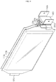
- FIG. 1 is a perspective view showing a battery module according to an embodiment of the present disclosure
- FIG. 2 is an exploded perspective view showing a battery module according to an embodiment of the present disclosure
- FIG. 3 is a diagram showing the battery module according to an embodiment of the present disclosure before its volume increases.
- a battery module may include a battery cell 110a, 110b, a bus bar 200a, 200b, a short-circuit unit 300 and a cartridge 400.
- the battery cell 110a, 110b may be provided in plural, and the battery cells 110a, 110b may be stacked side by side in the right and left direction.
- the kind of the battery cell 110a, 110b is not specially limited, and various kinds of secondary batteries may be used for the battery module according to the present disclosure.
- the battery cell 110a, 110b may be a lithium ion battery, a lithium polymer battery, a nickel cadmium battery, a nickel hydride battery, a nickel zinc battery, or the like.
- the battery cell 110a, 110b may be a lithium secondary battery.
- the battery cell 110a, 110b may be classified into a pouch type, a cylindrical type, a rectangular type and the like, depending on its exterior.
- the battery cell 110a, 110b of the battery module according to the present disclosure may be a pouch-type secondary battery.
- each battery cell 110a, 110b has broad surfaces at right and left sides thereof, and the broad surfaces of the battery cells 110a, 110b may be provided to face to each other.
- each battery cell 110a, 110b may include an electrode lead 120a, 120b that is bent while protruding toward the front.
- the electrode lead 120a, 120b may include a positive electrode lead and a negative electrode lead.
- the positive electrode lead may be connected to a positive electrode plate of an electrode assembly
- the negative electrode lead may be connected to a negative electrode plate of the electrode assembly.
- the battery cell 110a, 110b may include a first battery cell 110a located at a left side and a second battery cell 110b located at a right side.
- the electrode leads of the first battery cell 110a and the second battery cell 110b may be disposed so that the electrode leads 120a, 120b having the different polarity are oriented in the same direction.
- the first battery cell 110a may be disposed so that the first electrode lead 120a having a positive polarity is oriented to the front direction
- the second battery cell 110b may be disposed so that the second electrode lead 120b having a negative polarity is oriented to the front direction.
- first battery cell 110a may be disposed so that the second electrode lead 120b having a negative polarity is oriented to the rear direction, and the second battery cell 110b may be disposed such that the first electrode lead 120a having a positive polarity is oriented to the rear direction.
- the second electrode lead 120b of the first battery cell 110a and the first electrode lead 120a of the second battery cell 110b may be electrically connected.
- first electrode lead 120a of the first battery cell 110a may electrically connected to the first bus bar 200a, explained later, to receive a positive voltage from an external power source.
- second electrode lead 120b of the second battery cell 110b may be electrically connected to the second bus bar 200b, explained later, to receive a negative voltage from the external power source.
- the first bus bar 200a may be a bus bar that is electrically connected to the first electrode lead 120a of the first battery cell 110a, among the bus bars 200a, 200b according to the present disclosure
- the second bus bar 200b may be a bus bar that is electrically connected to the second electrode lead 120b of the second battery cell 110b, among the bus bars 200a, 200b according to the present disclosure.
- connection structure between the first electrode lead 120a of the first battery cell 110a and the first bus bar 200a and the connection structure between the second electrode lead 120b of the second battery cell 110b and the second bus bar 200b according to the present disclosure will be described in detail.
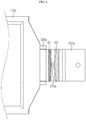
- FIG. 4 is a diagram showing only a first battery cell, a first bus bar, a second battery cell and a second bus bar of the battery module according to an embodiment of the present disclosure.
- the first electrode lead 120a of the first battery cell 110a may protrude toward the front from the first battery cell 110a and be bent about perpendicular toward the outside of the battery module to be in surface contact with the first bus bar 200a.
- the second electrode lead 120b of the second battery cell 110b may protrude toward the front from the second battery cell 110b and be bent at about a right angle in an outer direction of the battery module, namely in a direction opposite to the bending direction of the first electrode lead 120a of the first battery cell 110a, to make surface contact with the second bus bar 200b.
- the first bus bar 200a and the second bus bar 200b may have a shape in which a plate elongated in a vertical direction is bent several times at a right angle.
- the first bus bar 200a may include a first bending portion B1 that is in surface contact with the first electrode lead 120a of the first battery cell 110a and bent perpendicularly toward the front, a second bending portion B2 extending from the first bending portion B1 and bent toward the inside of the battery module, a third bending portion B3 extending from the second bending portion B2 and bent toward the front of the battery module, a fourth bending portion B4 extending from the third bending portion B3 and bent toward the outside of the battery module, and a fifth bending portion B5 extending from the fourth bending portion B4 and bent toward the front of the battery module.
- the second bus bar 200b may include a sixth bending portion B6 that is in contact with the second electrode lead 120b of the second battery cell 110b and bent toward the front, a seventh bending portion B7 extending from the sixth bending portion B6 and bent toward the inside of the battery module, an eighth bending portion B8 extending from the seventh bending portion B7 and bent toward the front of the battery module, a ninth bending portion B9 extending from the eighth bending portion B8 and bent toward the outside of the battery module, and tenth bending portion B10 extending from the ninth bending portion B9 and bent toward the front of the battery module.
- first bus bar 200a and the second bus bar 200b may be bent from the second bending portion B2 and the seventh bending portion B7 and extend toward each other to reduce the separation distance, and may be bent from the third bending portion B3 and the eighth bending portion B8 toward the front of the battery module to maintain the separation distance.
- the third bending portion B3 of the first bus bar 200a and the eighth bending portion B8 of the second bus bar 200b are located close to each other.
- a short-circuit terminal 322 FIG. 3
- the short-circuit terminal 322 may simultaneously contact the first bus bar 200a and the second bus bar 200b to electrically short-circuit the first bus bar 200a and the second bus bar 200b.
- the first electrode lead 120a of the first battery cell 110a and the first bus bar 200a may be partly inserted into and supported by a support groove 430 ( FIG. 2 ) of the cartridge 400 ( FIG. 2 ), explained later, in a state of being surface-contacted and electrically connected to each other.
- the second electrode lead 120b of the second battery cell 110b and the second bus bar 200b may be partly inserted into and supported by the supporting groove 430 ( FIG. 2 ) of the cartridge 400 ( FIG. 2 ), explained later, in a state of being surface-contacted and electrically connected to each other.
- the cartridge 400 ( FIG. 2 ) will be described later in detail.
- FIG. 5 is a diagram showing a side of the battery module according to an embodiment of the present disclosure before a fracturing portion is fractured
- FIG. 6 is a diagram showing a side of the battery module according to an embodiment of the present disclosure after a fracturing portion is fractured.
- the first bus bar 200a may have a fracturing portion 210a that is formed in a region between the first bending portion B1 and the second bending portion B2 and has a narrower sectional area than the outer region between the first bending portion B1 and the second bending portion B2.
- the resistance may be increased.
- first bus bar 200a and the second bus bar 200b are electrically connected to form a short circuit between the first bus bar 200a and the second bus bar 200b ( FIG. 3 ), as shown in FIG. 6 , an overcurrent flows to the first bus bar 200a to generate a high-temperature resistance heat, so that the fracturing portion 210a may be fractured.
- a fracturing portion 210a of the first bus bar 200a that electrically connect the first electrode lead 120a of the first battery cell 110a and an external power source may be fractured to stop charging.
- the battery module according to the present disclosure may apply the expansive force generated by a volume increase due to overcharge of the first battery cell 110a to the short-circuit unit 300 ( FIG. 3 ) to electrically connect the first bus bar 200a and the second bus bar 200b ( FIG. 3 ). Subsequently, as the fracturing portion 210a of the first bus bar 200a is fractured due to the short circuit of high current flowing at the first bus bar 200a and the second bus bar 200b ( FIG. 3 ), the battery module according to the present disclosure may stop charging to prevent the overcharge of the battery module from progressing.
- fracturing portion 210a of the battery module according to an embodiment of the present disclosure is formed at the first bus bar 200a
- a fracturing portion of a battery module according to another embodiment of the present disclosure may be formed at the second bus bar
- a fracturing portion of a battery module according to still another embodiment of the present disclosure may be formed at both the first bus bar and the second bus bar.
- the fracturing portion 210a may be formed to have a narrower width than the adjacent region as described above.
- the fracturing portion 210a may be made of a metal having a melting point lower than that of the adjacent region, and the fracturing portion 210a may adopt any configuration as long as it is able to function as a fuse.
- FIG. 7 is a perspective view showing a short-circuit unit of the battery module according to an embodiment of the present disclosure
- FIG. 8 is a diagram showing a top surface of the battery module according to an embodiment of the present disclosure, where a cartridge among components of the battery module is partially sectioned.
- the short-circuit unit 300 may cause a short circuit by receiving an expansive force due to a volume increase of at least one of the first battery cell 110a and the second battery cell 110b to move toward the first bus bar 200a and the second bus bar 200b and contact the first bus bar 200a and the second bus bar 200b.
- the short-circuit unit 300 may include an elastic member 310, a slide bar 320 and expansive force transmitting units 330a, 330b.
- one end of the elastic member 310 may be supported to the inner side of the cartridge 400 to provide an elastic force in a direction opposite to the expansive force.
- the elastic member 310 may be formed so that a spring S is inserted between a first plate PI contacting one end of the slide bar 320 and a second plate P2 contacting the inner side of the cartridge 400, to provide an elastic force in a direction (a) toward the slide bar 320 and in a direction (b) toward the cartridge 400.
- the slide bar 320 may have a short-circuit terminal 322 that contacts the first plate PI of the elastic member 310 at one end to which the elastic force is applied from the elastic member 310.
- the short-circuit terminal 322 having a plate shape provided at one end of the slide bar 320 may be in surface contact with the first plate PI of the elastic member 310 to receive an elastic force in the direction (a).
- the slide bar 320 may have a rack gear 321 provided at the other end thereof and having a plurality of protrusions protruded along the surface thereof.
- the slide bar 320 may include a first plate elongated from the other end to one end and a second plate perpendicularly contacting the first plate at one end of the first plate. That is, the slide bar 320 may be formed to have a 'T' shape as two plates are in contact perpendicularly.
- the rack gear 321 described above is formed at the surface of the other end of the first plate, and the rack gear 321 may have a plurality of protrusions.
- the expansive force transmitting units 330a, 330b include a first expansive force transmitting unit 330a that contacts the rack gear 321 at a left surface among the surfaces of the slide bar 320 at the other end thereof, and a second expansive force transmitting unit 330b that contacts the rack gear 321 formed at a right surface.
- the first expansive force transmitting unit 330a and the second expansive force transmitting unit 330b have the same components and function and may be shaped symmetrically in the right and left direction from one end to the other end thereof.
- the first expansive force transmitting unit 330a may include a pinion gear 331a provided at one end thereof to engage with the rack gear 321 and support the other end of the slide bar 320.
- the pinion gear 331a provided at one end of the first expansive force transmitting unit 330a has a disk shape, and a plurality of projections may be formed along the outer circumference of the disk.
- the plurality of projections of the pinion gear 331a may be inserted between the plurality of projections of the rack gear 321 to fix and support the first expansive force transmitting unit 330a to the slide bar 320.
- the other end of the first expansive force transmitting unit 330a may come into contact with one end of the first battery cell 110a to receive an expansive force when the volume of the first battery cell 110a increases.
- a plurality of bent portions may be formed between one end and the other end of the first expansive force transmitting unit 330a and be disposed in a space formed between the first battery cell 110a and the slide bar 320.
- the other end of the slide bar 320 is gear-coupled with the first expansive force transmitting unit 330a and the second expansive force transmitting unit 330b which are in contact with the first battery cell 110a and the second battery cell 110b, respectively, and an elastic force may be applied to one end of the slide bar 320 from the elastic member 310 in contact with the inner side of the cartridge 400.
- the short-circuit terminal 322 of the slide bar 320 may receive an elastic force from the elastic member 310 as much as to be spaced from the first bus bar 200a and the second bus bar 200b, and thus may not contact the first bus bar 200a and the second bus bar 200b.
- FIG. 9 is a diagram showing the top surface of the battery module according to an embodiment of the present disclosure, after its volume increases.
- the volume of at least one of the first battery cell 110a and the second battery cell 110b may increase.
- an expansive force may be applied to the first expansive force transmitting unit 330a
- an expansive force may be applied to the second expansive force transmitting unit 330b.
- the first expansive force transmitting unit 330a and the second expansive force transmitting unit 330b may receive an expansive force oriented to the front.
- the first expansive force transmitting unit 330a and the second expansive force transmitting unit 330b may transmit the expansive force to the gear-coupled slide bar 320, and the slide bar 320 receiving the expansive force may move in a direction (c) toward the first bus bar 200a and the second bus bar 200b.
- the short-circuit terminal 322 placed at the other end of the slide bar 320 may contact the first bus bar 200a and the second bus bar 200b to electrically connect the first bus bar 200a and the second bus bar 200b.
- the circuit including the short-circuit terminal 322, the first bus bar 200a and the second bus bar 200b may form a short circuit.
- the short-circuit terminal 322 may be made of a conductive material.
- the short-circuit unit 300 may receive an expansive force from the first battery cell 110a and the second battery cell 110b to move toward the first bus bar 200a and the second bus bar 200b and electrically connect the first bus bar 200a and the second bus bar 200b, thereby generating a short circuit.
- the short-circuit unit 300 may electrically connect the first bus bar 200a and the second bus bar 200b to cause a short circuit.
- the slide bar 320 may receive an expansive force from only the first expansive force transmitting unit 330a to move toward the first bus bar 200a and the second bus bar 200b.
- the slide bar 320 may receive the expansive force due to the volume increase and move toward the first bus bar 200a and the second bus bar 200b to generate a short circuit by electrically connecting the first bus bar 200a and the second bus bar 200b.
- the slide bar 320 may move toward the first bus bar 200a and the second bus bar 200b by receiving the expansive force from only the second expansive force transmitting unit 330b.
- the slide bar 320 may receive the expansive force according to the volume increase and move toward the first bus bar 200a and the second bus bar 200b to generate a short circuit by electrically connecting the first bus bar 200a and the second bus bar 200b.
- FIG. 10 is an equivalent circuit diagram before overcharge occurs at the battery module according to an embodiment of the present disclosure
- FIG. 11 is an equivalent circuit diagram just after a short-circuit unit moves after overcharge occurs at the battery module according to an embodiment of the present disclosure
- FIG. 12 is an equivalent circuit diagram after the short-circuit unit moves to fracture fracturing portion after overcharge occurs at the battery module according to an embodiment of the present disclosure.
- the battery module according to the present disclosure if the battery module according to the present disclosure is not overcharged but operates normally, as shown in FIG. 10 , the volume of the battery cell 110a and the second battery cell 110b does not increase, and thus the first bus bar 200a and the second bus bar 200b may not cause an electrical short circuit.
- the short-circuit unit 300 may receive an expansive force to move toward the first bus bar 200a and the second bus bar 200b. Accordingly, the short-circuit terminal 322 ( FIG. 8 ) of the short-circuit unit 300 may contact the first bus bar 200a and the second bus bar 200b and electrically connect the first bus bar 200a and the second bus bar 200b to generate a short circuit.
- a short circuit including the short-circuit unit 300, the first bus bar 200a and the second bus bar 200b is formed so that a high current I may flow.
- the fracturing portion 210a having great resistance due to a narrow cross section generates high-temperature resistance heat and thus is fractured, thereby cutting the power supplied from the external power source to the battery module and thus preventing the overcharge.
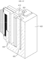
- FIG. 13 is a diagram showing a section of the cartridge of the battery module according to an embodiment of the present disclosure
- FIG. 14 is a perspective view showing an inside of a cartridge of the battery module according to an embodiment of the present disclosure.
- the cartridge 400 may be located between the first battery cell 110a and the second battery cell 110b to accommodate or support a part of the first electrode lead 120a of the first battery cell 110a, the second electrode lead 120b of the second battery cell 110b, the first bus bar 200a, the second bus bar 200b and the short-circuit unit 300.
- the cartridge 400 may support the first electrode lead 120a of the first battery cell 110a and the first bus bar 200a, which are in surface contact with each other to be electrically connected, at a lower portion thereof, and may support the second electrode lead 120b of the second battery cell 110b and the second bus bar 200b, which are in surface contact with each other to be electrically connected, at a lower portion thereof.
- the cartridge 400 may have a support groove 430 formed to have a shape corresponding to the bending shape of the first electrode lead 120a of the first battery cell 110a, the second electrode lead 120b of the second battery cell 110b, the first bus bar 200a and the second bus bar 200b.
- the cartridge 400 may have an accommodation portion 410 formed therein with a shape corresponding to an appearance of the short-circuit unit 300 and an appearance of the short-circuit unit 300 to accommodate the short-circuit unit 300 therein.
- the accommodation portion 410 of the cartridge 400 may be formed to correspond to the volume when the elastic member 310 of the short-circuit unit 300 is restored from a deformed state.
- the accommodation portion 410 of the cartridge 400 may be formed to correspond to the volume that changes when the elastic member 310 ( FIG. 7 ) of the short-circuit unit 300 repeats deformation and restoration.
- the accommodation portion 410 may be formed at the inside of the cartridge 400 to have a shape corresponding to an appearance of the short-circuit unit 300.
- the battery module according to the present disclosure may improve the stability of the battery module by fracturing the first bus bar accurately when the battery cell abnormally expands to cut off the power supplied from the external voltage source and thus prevent the overcharge of the battery module.
- a battery pack according to the present disclosure includes at least one battery module as described above.
- the battery pack may further include a case for accommodating the battery module, and various devices for controlling charge/discharge of the battery module such as a battery management system (BMS), a current sensor and a fuse.
- BMS battery management system
- the battery pack according to an embodiment of the present disclosure may include the first bus bar, the second bus bar, the short-circuit unit and the cartridge at each battery module to cut off the power supplied from the external voltage source by fracturing the first bus bar when the battery cell abnormally expands, so that overcharge is prevented for each battery module.
- the battery module according to the present disclosure may be applied to a vehicle such as an electric vehicle and a hybrid vehicle. That is, the vehicle according to the present disclosure may include the battery module of the present disclosure.
Landscapes
- Chemical & Material Sciences (AREA)
- Chemical Kinetics & Catalysis (AREA)
- Electrochemistry (AREA)
- General Chemical & Material Sciences (AREA)
- Engineering & Computer Science (AREA)
- General Engineering & Computer Science (AREA)
- Mechanical Engineering (AREA)
- Manufacturing & Machinery (AREA)
- Connection Of Batteries Or Terminals (AREA)
- Battery Mounting, Suspending (AREA)
Claims (12)
- Module de batterie, comprenant :une première barre omnibus (200a) électriquement connectée à un premier fil d'électrode (120a) d'un premier élément de batterie (110a) ;une seconde barre omnibus (200b) électriquement connectée à un second fil d'électrode (120b) d'un second élément de batterie (110b) ;une unité de court-circuit (300) configurée pour se déplacer vers la première barre omnibus (200a) et la seconde barre omnibus (200b) par la réception d'une force d'expansion due à une augmentation de volume d'au moins l'un du premier élément de batterie (110a) et du second élément de batterie (110b) de sorte que la première barre omnibus (200a) et la seconde barre omnibus (200b) sont électriquement connectées pour générer un court-circuit ; caractérisé parune cartouche (400) configurée pour recevoir ou porter au moins une portion du premier fil d'électrode (120a), du second fil d'électrode (120b), de la première barre omnibus (200a), de la seconde barre omnibus (200b) et de l'unité de court-circuit (300),dans lequel l'unité de court-circuit (300) inclut :un élément élastique (310) ayant une extrémité portée sur un côté interne de la cartouche (400) et configuré pour fournir une force élastique dans une direction opposée à la force d'expansion ;une barre coulissante (320) ayant une borne de court-circuit (322) ménagée à une extrémité de celle-ci pour venir en contact avec l'autre extrémité de l'élément élastique (310) et recevoir la force élastique de l' élément élastique (310), la barre coulissante (320) ayant une crémaillère (321) formée le long d'une surface de l'autre extrémité de celle-ci ; etune unité de transmission de force d'expansion (330a, 330b) ayant un pignon (331a, 331b) ménagé à une extrémité de celle-ci pour venir en prise avec la crémaillère (321) et porter l'autre extrémité de la barre coulissante (320), l'unité de transmission de force d'expansion (330a, 330b) ayant l'autre extrémité qui est en contact avec une extrémité de chacun du premier élément de batterie (110a) et du second élément de batterie (110b) pour recevoir la force d'expansion.
- Module de batterie selon la revendication 1,
dans lequel lorsque le volume à la fois du premier élément de batterie (110a) et du second élément de batterie (110b) n'augmente pas, la barre coulissante (320) reçoit uniquement la force élastique de sorte que la borne de court-circuit (322) est espacée du premier élément de batterie (110a) et du second élément de batterie (110b). - Module de batterie selon la revendication 1,
dans lequel lorsque le volume d'au moins l'un du premier élément de batterie (110a) et du second élément de batterie (110b) augmente, l'unité de transmission de force d'expansion (330a, 330b) reçoit la force d'expansion pour se déplacer vers la première barre omnibus (110a) et la seconde barre omnibus (110b) et transmet la force d'expansion reçue à la barre coulissante (320) par l'intermédiaire de la crémaillère (321) mise en prise avec le pignon (331a, 331b). - Module de batterie selon la revendication 1,
dans lequel lorsque le volume d'au moins l'un du premier élément de batterie (110a) et du second élément de batterie (110b) augmente, la barre coulissante (320) reçoit la force d'expansion par l'intermédiaire de la crémaillère (321) mise en prise avec le pignon (331a, 331b) pour se déplacer vers la première barre omnibus (200a) et la seconde barre omnibus (200b). - Module de batterie selon la revendication 1,
dans lequel la borne de court-circuit (322) vient en contact avec la première barre omnibus (200a) et la seconde barre omnibus (200b) et connecte électriquement la première barre omnibus (200a) et la seconde barre omnibus (200b) pour générer un court-circuit. - Module de batterie selon la revendication 1,
dans lequel la borne de court-circuit (322) est constituée d'un matériau conducteur. - Module de batterie selon la revendication 1,
dans lequel la cartouche (400) possède une portion de réception (410) formée dans celle-ci avec une géométrie correspondant à une apparence de l'unité de court-circuit (300) pour recevoir l'unité de court-circuit (300) dans celle-ci. - Module de batterie selon la revendication 7,
dans lequel la portion de réception (410) est formée pour correspondre au volume d'un élément élastique (310) en fonction d'un état de rappel de l' élément élastique (310). - Module de batterie selon la revendication 1,
dans lequel la cartouche (400) porte au moins une portion de chacun du premier fil d'électrode (120a) et de la première barre omnibus (200a) qui sont en contact de surface l'un avec l'autre pour être électriquement connectés, et porte au moins une portion de chacun du second fil d'électrode (120b) et de la seconde barre omnibus (200b) qui sont en contact de surface l'un avec l'autre pour être électriquement connectés. - Module de batterie selon la revendication 1,
dans lequel au moins l'une de la première barre omnibus (200a) et de la seconde barre omnibus (200b) inclut en outre une portion de fracturation (210) qui est fracturée pour couper une connexion électrique vers l'extérieur lorsque le court-circuit est généré. - Bloc-batterie comprenant un module de batterie selon l'une quelconque des revendications 1 à 10.
- Véhicule comprenant un module de batterie selon l'une quelconque des revendications 1 à 10.
Priority Applications (1)
| Application Number | Priority Date | Filing Date | Title |
|---|---|---|---|
| PL18817230T PL3540823T3 (pl) | 2017-06-15 | 2018-06-11 | Moduł akumulatorowy oraz zawierający go pakiet akumulatorowy i pojazd |
Applications Claiming Priority (2)
| Application Number | Priority Date | Filing Date | Title |
|---|---|---|---|
| KR1020170076020A KR102201347B1 (ko) | 2017-06-15 | 2017-06-15 | 배터리 모듈과 이를 포함하는 배터리 팩 및 자동차 |
| PCT/KR2018/006604 WO2018230907A1 (fr) | 2017-06-15 | 2018-06-11 | Module de batterie et bloc-batterie et véhicule les comprenant |
Publications (3)
| Publication Number | Publication Date |
|---|---|
| EP3540823A1 EP3540823A1 (fr) | 2019-09-18 |
| EP3540823A4 EP3540823A4 (fr) | 2020-05-06 |
| EP3540823B1 true EP3540823B1 (fr) | 2020-10-21 |
Family
ID=64660968
Family Applications (1)
| Application Number | Title | Priority Date | Filing Date |
|---|---|---|---|
| EP18817230.8A Active EP3540823B1 (fr) | 2017-06-15 | 2018-06-11 | Module de batterie et bloc-batterie et véhicule les comprenant |
Country Status (7)
| Country | Link |
|---|---|
| US (1) | US11011802B2 (fr) |
| EP (1) | EP3540823B1 (fr) |
| JP (1) | JP7027638B2 (fr) |
| KR (1) | KR102201347B1 (fr) |
| CN (1) | CN109923695B (fr) |
| PL (1) | PL3540823T3 (fr) |
| WO (1) | WO2018230907A1 (fr) |
Families Citing this family (4)
| Publication number | Priority date | Publication date | Assignee | Title |
|---|---|---|---|---|
| KR102163656B1 (ko) * | 2017-06-27 | 2020-10-08 | 주식회사 엘지화학 | 배터리 모듈과 이를 포함하는 배터리 팩 및 자동차 |
| US11063320B2 (en) | 2019-01-08 | 2021-07-13 | Lg Chem, Ltd. | Terminal busbar |
| KR20210064844A (ko) * | 2019-11-26 | 2021-06-03 | 주식회사 엘지에너지솔루션 | 전지 모듈 및 이를 포함하는 전지 팩 |
| EP4222809A1 (fr) * | 2020-10-02 | 2023-08-09 | Blue Solutions Canada Inc. | Unité de stockage d'énergie comprenant un ensemble bâti et une pluralité de modules de batterie |
Family Cites Families (40)
| Publication number | Priority date | Publication date | Assignee | Title |
|---|---|---|---|---|
| US5800937A (en) | 1997-05-02 | 1998-09-01 | Motorola, Inc. | Current interrupt device for secondary batteries |
| JP2006504244A (ja) * | 2002-10-25 | 2006-02-02 | ラヨヴァック・コーポレーション | 電気化学電池の充電調整方法及び装置 |
| JP2004319463A (ja) | 2003-03-28 | 2004-11-11 | Matsushita Electric Ind Co Ltd | 二次電池 |
| WO2005114810A1 (fr) * | 2004-05-17 | 2005-12-01 | Railpower Technologies Corp. | Dérivation automatique de shunt de cellule de batterie |
| KR100542677B1 (ko) * | 2004-06-25 | 2006-01-11 | 삼성에스디아이 주식회사 | 이차 전지 |
| KR100579377B1 (ko) * | 2004-10-28 | 2006-05-12 | 삼성에스디아이 주식회사 | 이차 전지 |
| BRPI0519197A2 (pt) * | 2004-12-23 | 2008-12-30 | Siemens Ag | processo e dispositivo para a operaÇço segura de um aparelho de comutaÇço |
| KR100764618B1 (ko) * | 2005-09-07 | 2007-10-08 | 주식회사 엘지화학 | 안전장치를 구비하고 있는 이차전지 |
| JP5092331B2 (ja) * | 2006-09-29 | 2012-12-05 | パナソニック株式会社 | 鉛蓄電池用エキスパンド格子および鉛蓄電池 |
| CN101012798A (zh) * | 2007-01-24 | 2007-08-08 | 潍柴动力股份有限公司 | 一种柴油机电起动装置 |
| WO2009066880A2 (fr) * | 2007-11-21 | 2009-05-28 | Lg Chem, Ltd. | Module de batterie à sécurité améliorée et bloc batterie de taille moyenne ou grande le contenant |
| CN201178120Y (zh) * | 2008-04-11 | 2009-01-07 | 山东电力研究院 | 移动机器人电池充电连接器 |
| KR101128423B1 (ko) * | 2008-04-28 | 2012-03-23 | 에스케이이노베이션 주식회사 | 전기자동차용 2차 전지의 안전 스위치 및 이를 이용한전기자동차용 2차 전지의 충방전 시스템 |
| KR101041153B1 (ko) | 2009-03-04 | 2011-06-13 | 에스비리모티브 주식회사 | 이차전지 및 그 모듈 |
| KR101072955B1 (ko) * | 2009-08-14 | 2011-10-12 | 에스비리모티브 주식회사 | 전지 모듈 |
| DE102009050316A1 (de) * | 2009-10-16 | 2011-04-21 | Elringklinger Ag | Zellverbinder |
| JP5331085B2 (ja) * | 2010-11-09 | 2013-10-30 | 三菱重工業株式会社 | 電池 |
| KR101546545B1 (ko) | 2010-12-09 | 2015-08-24 | 주식회사 엘지화학 | 파우치형 리튬이차전지 |
| WO2012157855A1 (fr) | 2011-05-17 | 2012-11-22 | 주식회사 엘지화학 | Bloc-batterie offrant une sécurité améliorée |
| KR101359310B1 (ko) * | 2011-07-25 | 2014-02-07 | 주식회사 엘지화학 | 안전성이 향상된 전지팩 |
| KR101383167B1 (ko) | 2011-10-20 | 2014-04-10 | 주식회사 엘지화학 | 안전성이 향상된 전지팩 |
| EP2634835A1 (fr) * | 2011-12-02 | 2013-09-04 | Hitachi, Ltd. | Système de batterie |
| KR101404712B1 (ko) * | 2012-01-26 | 2014-06-09 | 주식회사 엘지화학 | 안전성이 향상된 전지팩 |
| KR101614434B1 (ko) * | 2012-08-31 | 2016-05-02 | 주식회사 엘지화학 | 안전성이 향상된 배터리 셀 |
| KR101524002B1 (ko) * | 2012-09-24 | 2015-05-29 | 주식회사 엘지화학 | 자동 전자 개폐기를 적용한 전지팩 |
| KR101944837B1 (ko) * | 2012-09-28 | 2019-02-07 | 에스케이이노베이션 주식회사 | 이차 전지용 배터리 셀의 과충전 방지장치 |
| KR101428331B1 (ko) | 2012-12-27 | 2014-08-07 | 현대자동차주식회사 | 차량용 배터리모듈의 안전장치 |
| SE537191C2 (sv) * | 2013-05-31 | 2015-03-03 | Scania Cv Ab | Intrinsiskt överladdningsskydd för battericell |
| KR101449307B1 (ko) * | 2013-06-28 | 2014-10-08 | 현대자동차주식회사 | 배터리 안전장치 |
| KR101449306B1 (ko) * | 2013-06-28 | 2014-10-08 | 현대자동차주식회사 | 배터리 과충전 보호장치 |
| KR101846418B1 (ko) * | 2013-12-17 | 2018-04-06 | 지멘스 악티엔게젤샤프트 | Hvdc 컨버터를 위한 보호 전자 모듈 |
| KR101500222B1 (ko) | 2013-12-18 | 2015-03-06 | 현대자동차주식회사 | 배터리 과충전 방지 장치 |
| JP2015118792A (ja) | 2013-12-18 | 2015-06-25 | トヨタ自動車株式会社 | 二次電池モジュール |
| JP6281398B2 (ja) | 2014-04-21 | 2018-02-21 | 株式会社豊田自動織機 | 電池モジュール |
| EP3151328B1 (fr) * | 2014-05-26 | 2022-03-23 | W.L. Gore & Associates G.K. | Batterie rechargeable et séparateur utilisé dans cette dernière |
| KR20160026469A (ko) * | 2014-09-01 | 2016-03-09 | 에스케이이노베이션 주식회사 | 저전압 센싱모듈 일체형 버스바를 구비한 배터리모듈 |
| KR20160030688A (ko) | 2014-09-11 | 2016-03-21 | 주식회사 루트제이드 | 과전류 차단수단이 구비된 이차전지 |
| KR20170016065A (ko) | 2015-08-03 | 2017-02-13 | 에스케이이노베이션 주식회사 | 이차 전지 |
| KR20170076020A (ko) | 2015-12-24 | 2017-07-04 | 주식회사 대유위니아 | 에어컨 |
| KR102201344B1 (ko) * | 2017-05-26 | 2021-01-08 | 주식회사 엘지화학 | 배터리 모듈과 이를 포함하는 배터리 팩 및 자동차 |
-
2017
- 2017-06-15 KR KR1020170076020A patent/KR102201347B1/ko active IP Right Grant
-
2018
- 2018-06-11 CN CN201880004176.0A patent/CN109923695B/zh active Active
- 2018-06-11 WO PCT/KR2018/006604 patent/WO2018230907A1/fr unknown
- 2018-06-11 PL PL18817230T patent/PL3540823T3/pl unknown
- 2018-06-11 JP JP2019529564A patent/JP7027638B2/ja active Active
- 2018-06-11 US US16/336,337 patent/US11011802B2/en active Active
- 2018-06-11 EP EP18817230.8A patent/EP3540823B1/fr active Active
Non-Patent Citations (1)
| Title |
|---|
| None * |
Also Published As
| Publication number | Publication date |
|---|---|
| WO2018230907A1 (fr) | 2018-12-20 |
| KR102201347B1 (ko) | 2021-01-08 |
| CN109923695A (zh) | 2019-06-21 |
| US20190245186A1 (en) | 2019-08-08 |
| EP3540823A1 (fr) | 2019-09-18 |
| JP2020501312A (ja) | 2020-01-16 |
| JP7027638B2 (ja) | 2022-03-02 |
| PL3540823T3 (pl) | 2021-01-25 |
| KR20180136803A (ko) | 2018-12-26 |
| US11011802B2 (en) | 2021-05-18 |
| CN109923695B (zh) | 2021-11-12 |
| EP3540823A4 (fr) | 2020-05-06 |
Similar Documents
| Publication | Publication Date | Title |
|---|---|---|
| EP3512008B1 (fr) | Module de batterie et bloc-batterie, et véhicule les comprenant | |
| US10892468B2 (en) | Battery module with short-circuit unit, and battery pack and vehicle including the same | |
| JP5575761B2 (ja) | 安全性を改良した中型又は大型バッテリーパック | |
| KR100881641B1 (ko) | 안전 시스템을 구비한 중대형 전지팩 | |
| EP3540823B1 (fr) | Module de batterie et bloc-batterie et véhicule les comprenant | |
| EP3540822B1 (fr) | Module de batterie et bloc-batterie, et automobile les comprenant | |
| KR102249457B1 (ko) | 배터리 모듈과 이를 포함하는 배터리 팩 및 자동차 | |
| KR102250180B1 (ko) | 배터리 모듈과 이를 포함하는 배터리 팩 및 자동차 | |
| KR102378571B1 (ko) | 배터리 모듈, 이를 포함하는 배터리 팩 및 자동차 | |
| KR102267056B1 (ko) | 배터리 모듈과 이를 포함하는 배터리 팩 및 자동차 | |
| CN109891636B (zh) | 电池模块和包括该电池模块的电池组 | |
| KR102308168B1 (ko) | 배터리 모듈과 이를 포함하는 배터리 팩 및 자동차 |
Legal Events
| Date | Code | Title | Description |
|---|---|---|---|
| STAA | Information on the status of an ep patent application or granted ep patent |
Free format text: STATUS: THE INTERNATIONAL PUBLICATION HAS BEEN MADE |
|
| PUAI | Public reference made under article 153(3) epc to a published international application that has entered the european phase |
Free format text: ORIGINAL CODE: 0009012 |
|
| STAA | Information on the status of an ep patent application or granted ep patent |
Free format text: STATUS: REQUEST FOR EXAMINATION WAS MADE |
|
| 17P | Request for examination filed |
Effective date: 20190613 |
|
| AK | Designated contracting states |
Kind code of ref document: A1 Designated state(s): AL AT BE BG CH CY CZ DE DK EE ES FI FR GB GR HR HU IE IS IT LI LT LU LV MC MK MT NL NO PL PT RO RS SE SI SK SM TR |
|
| AX | Request for extension of the european patent |
Extension state: BA ME |
|
| A4 | Supplementary search report drawn up and despatched |
Effective date: 20200403 |
|
| RIC1 | Information provided on ipc code assigned before grant |
Ipc: H01M 2/20 20060101ALI20200330BHEP Ipc: F16H 19/04 20060101ALI20200330BHEP Ipc: H01M 2/34 20060101AFI20200330BHEP Ipc: H01M 2/10 20060101ALI20200330BHEP |
|
| GRAP | Despatch of communication of intention to grant a patent |
Free format text: ORIGINAL CODE: EPIDOSNIGR1 |
|
| STAA | Information on the status of an ep patent application or granted ep patent |
Free format text: STATUS: GRANT OF PATENT IS INTENDED |
|
| GRAS | Grant fee paid |
Free format text: ORIGINAL CODE: EPIDOSNIGR3 |
|
| DAV | Request for validation of the european patent (deleted) | ||
| DAX | Request for extension of the european patent (deleted) | ||
| INTG | Intention to grant announced |
Effective date: 20200818 |
|
| GRAA | (expected) grant |
Free format text: ORIGINAL CODE: 0009210 |
|
| STAA | Information on the status of an ep patent application or granted ep patent |
Free format text: STATUS: THE PATENT HAS BEEN GRANTED |
|
| AK | Designated contracting states |
Kind code of ref document: B1 Designated state(s): AL AT BE BG CH CY CZ DE DK EE ES FI FR GB GR HR HU IE IS IT LI LT LU LV MC MK MT NL NO PL PT RO RS SE SI SK SM TR |
|
| REG | Reference to a national code |
Ref country code: GB Ref legal event code: FG4D |
|
| REG | Reference to a national code |
Ref country code: CH Ref legal event code: EP |
|
| REG | Reference to a national code |
Ref country code: IE Ref legal event code: FG4D |
|
| REG | Reference to a national code |
Ref country code: DE Ref legal event code: R096 Ref document number: 602018009002 Country of ref document: DE |
|
| REG | Reference to a national code |
Ref country code: AT Ref legal event code: REF Ref document number: 1326758 Country of ref document: AT Kind code of ref document: T Effective date: 20201115 |
|
| REG | Reference to a national code |
Ref country code: DE Ref legal event code: R079 Ref document number: 602018009002 Country of ref document: DE Free format text: PREVIOUS MAIN CLASS: H01M0002340000 Ipc: H01M0050572000 |
|
| REG | Reference to a national code |
Ref country code: SE Ref legal event code: TRGR |
|
| REG | Reference to a national code |
Ref country code: AT Ref legal event code: MK05 Ref document number: 1326758 Country of ref document: AT Kind code of ref document: T Effective date: 20201021 |
|
| REG | Reference to a national code |
Ref country code: NL Ref legal event code: MP Effective date: 20201021 |
|
| PG25 | Lapsed in a contracting state [announced via postgrant information from national office to epo] |
Ref country code: PT Free format text: LAPSE BECAUSE OF FAILURE TO SUBMIT A TRANSLATION OF THE DESCRIPTION OR TO PAY THE FEE WITHIN THE PRESCRIBED TIME-LIMIT Effective date: 20210222 Ref country code: RS Free format text: LAPSE BECAUSE OF FAILURE TO SUBMIT A TRANSLATION OF THE DESCRIPTION OR TO PAY THE FEE WITHIN THE PRESCRIBED TIME-LIMIT Effective date: 20201021 Ref country code: FI Free format text: LAPSE BECAUSE OF FAILURE TO SUBMIT A TRANSLATION OF THE DESCRIPTION OR TO PAY THE FEE WITHIN THE PRESCRIBED TIME-LIMIT Effective date: 20201021 Ref country code: NO Free format text: LAPSE BECAUSE OF FAILURE TO SUBMIT A TRANSLATION OF THE DESCRIPTION OR TO PAY THE FEE WITHIN THE PRESCRIBED TIME-LIMIT Effective date: 20210121 Ref country code: GR Free format text: LAPSE BECAUSE OF FAILURE TO SUBMIT A TRANSLATION OF THE DESCRIPTION OR TO PAY THE FEE WITHIN THE PRESCRIBED TIME-LIMIT Effective date: 20210122 |
|
| REG | Reference to a national code |
Ref country code: LT Ref legal event code: MG4D |
|
| PG25 | Lapsed in a contracting state [announced via postgrant information from national office to epo] |
Ref country code: AT Free format text: LAPSE BECAUSE OF FAILURE TO SUBMIT A TRANSLATION OF THE DESCRIPTION OR TO PAY THE FEE WITHIN THE PRESCRIBED TIME-LIMIT Effective date: 20201021 Ref country code: ES Free format text: LAPSE BECAUSE OF FAILURE TO SUBMIT A TRANSLATION OF THE DESCRIPTION OR TO PAY THE FEE WITHIN THE PRESCRIBED TIME-LIMIT Effective date: 20201021 Ref country code: LV Free format text: LAPSE BECAUSE OF FAILURE TO SUBMIT A TRANSLATION OF THE DESCRIPTION OR TO PAY THE FEE WITHIN THE PRESCRIBED TIME-LIMIT Effective date: 20201021 Ref country code: IS Free format text: LAPSE BECAUSE OF FAILURE TO SUBMIT A TRANSLATION OF THE DESCRIPTION OR TO PAY THE FEE WITHIN THE PRESCRIBED TIME-LIMIT Effective date: 20210221 Ref country code: BG Free format text: LAPSE BECAUSE OF FAILURE TO SUBMIT A TRANSLATION OF THE DESCRIPTION OR TO PAY THE FEE WITHIN THE PRESCRIBED TIME-LIMIT Effective date: 20210121 |
|
| PG25 | Lapsed in a contracting state [announced via postgrant information from national office to epo] |
Ref country code: HR Free format text: LAPSE BECAUSE OF FAILURE TO SUBMIT A TRANSLATION OF THE DESCRIPTION OR TO PAY THE FEE WITHIN THE PRESCRIBED TIME-LIMIT Effective date: 20201021 Ref country code: NL Free format text: LAPSE BECAUSE OF FAILURE TO SUBMIT A TRANSLATION OF THE DESCRIPTION OR TO PAY THE FEE WITHIN THE PRESCRIBED TIME-LIMIT Effective date: 20201021 |
|
| REG | Reference to a national code |
Ref country code: DE Ref legal event code: R097 Ref document number: 602018009002 Country of ref document: DE |
|
| PG25 | Lapsed in a contracting state [announced via postgrant information from national office to epo] |
Ref country code: LT Free format text: LAPSE BECAUSE OF FAILURE TO SUBMIT A TRANSLATION OF THE DESCRIPTION OR TO PAY THE FEE WITHIN THE PRESCRIBED TIME-LIMIT Effective date: 20201021 Ref country code: RO Free format text: LAPSE BECAUSE OF FAILURE TO SUBMIT A TRANSLATION OF THE DESCRIPTION OR TO PAY THE FEE WITHIN THE PRESCRIBED TIME-LIMIT Effective date: 20201021 Ref country code: EE Free format text: LAPSE BECAUSE OF FAILURE TO SUBMIT A TRANSLATION OF THE DESCRIPTION OR TO PAY THE FEE WITHIN THE PRESCRIBED TIME-LIMIT Effective date: 20201021 Ref country code: CZ Free format text: LAPSE BECAUSE OF FAILURE TO SUBMIT A TRANSLATION OF THE DESCRIPTION OR TO PAY THE FEE WITHIN THE PRESCRIBED TIME-LIMIT Effective date: 20201021 Ref country code: SK Free format text: LAPSE BECAUSE OF FAILURE TO SUBMIT A TRANSLATION OF THE DESCRIPTION OR TO PAY THE FEE WITHIN THE PRESCRIBED TIME-LIMIT Effective date: 20201021 Ref country code: SM Free format text: LAPSE BECAUSE OF FAILURE TO SUBMIT A TRANSLATION OF THE DESCRIPTION OR TO PAY THE FEE WITHIN THE PRESCRIBED TIME-LIMIT Effective date: 20201021 |
|
| PLBE | No opposition filed within time limit |
Free format text: ORIGINAL CODE: 0009261 |
|
| STAA | Information on the status of an ep patent application or granted ep patent |
Free format text: STATUS: NO OPPOSITION FILED WITHIN TIME LIMIT |
|
| PG25 | Lapsed in a contracting state [announced via postgrant information from national office to epo] |
Ref country code: DK Free format text: LAPSE BECAUSE OF FAILURE TO SUBMIT A TRANSLATION OF THE DESCRIPTION OR TO PAY THE FEE WITHIN THE PRESCRIBED TIME-LIMIT Effective date: 20201021 |
|
| 26N | No opposition filed |
Effective date: 20210722 |
|
| PG25 | Lapsed in a contracting state [announced via postgrant information from national office to epo] |
Ref country code: IT Free format text: LAPSE BECAUSE OF FAILURE TO SUBMIT A TRANSLATION OF THE DESCRIPTION OR TO PAY THE FEE WITHIN THE PRESCRIBED TIME-LIMIT Effective date: 20201021 Ref country code: AL Free format text: LAPSE BECAUSE OF FAILURE TO SUBMIT A TRANSLATION OF THE DESCRIPTION OR TO PAY THE FEE WITHIN THE PRESCRIBED TIME-LIMIT Effective date: 20201021 |
|
| PG25 | Lapsed in a contracting state [announced via postgrant information from national office to epo] |
Ref country code: SI Free format text: LAPSE BECAUSE OF FAILURE TO SUBMIT A TRANSLATION OF THE DESCRIPTION OR TO PAY THE FEE WITHIN THE PRESCRIBED TIME-LIMIT Effective date: 20201021 |
|
| PG25 | Lapsed in a contracting state [announced via postgrant information from national office to epo] |
Ref country code: MC Free format text: LAPSE BECAUSE OF FAILURE TO SUBMIT A TRANSLATION OF THE DESCRIPTION OR TO PAY THE FEE WITHIN THE PRESCRIBED TIME-LIMIT Effective date: 20201021 |
|
| REG | Reference to a national code |
Ref country code: CH Ref legal event code: PL |
|
| REG | Reference to a national code |
Ref country code: BE Ref legal event code: MM Effective date: 20210630 |
|
| PG25 | Lapsed in a contracting state [announced via postgrant information from national office to epo] |
Ref country code: LU Free format text: LAPSE BECAUSE OF NON-PAYMENT OF DUE FEES Effective date: 20210611 |
|
| PG25 | Lapsed in a contracting state [announced via postgrant information from national office to epo] |
Ref country code: LI Free format text: LAPSE BECAUSE OF NON-PAYMENT OF DUE FEES Effective date: 20210630 Ref country code: IE Free format text: LAPSE BECAUSE OF NON-PAYMENT OF DUE FEES Effective date: 20210611 Ref country code: CH Free format text: LAPSE BECAUSE OF NON-PAYMENT OF DUE FEES Effective date: 20210630 |
|
| PG25 | Lapsed in a contracting state [announced via postgrant information from national office to epo] |
Ref country code: IS Free format text: LAPSE BECAUSE OF FAILURE TO SUBMIT A TRANSLATION OF THE DESCRIPTION OR TO PAY THE FEE WITHIN THE PRESCRIBED TIME-LIMIT Effective date: 20210221 |
|
| PG25 | Lapsed in a contracting state [announced via postgrant information from national office to epo] |
Ref country code: BE Free format text: LAPSE BECAUSE OF NON-PAYMENT OF DUE FEES Effective date: 20210630 |
|
| P01 | Opt-out of the competence of the unified patent court (upc) registered |
Effective date: 20230512 |
|
| PG25 | Lapsed in a contracting state [announced via postgrant information from national office to epo] |
Ref country code: CY Free format text: LAPSE BECAUSE OF FAILURE TO SUBMIT A TRANSLATION OF THE DESCRIPTION OR TO PAY THE FEE WITHIN THE PRESCRIBED TIME-LIMIT Effective date: 20201021 |
|
| PG25 | Lapsed in a contracting state [announced via postgrant information from national office to epo] |
Ref country code: HU Free format text: LAPSE BECAUSE OF FAILURE TO SUBMIT A TRANSLATION OF THE DESCRIPTION OR TO PAY THE FEE WITHIN THE PRESCRIBED TIME-LIMIT; INVALID AB INITIO Effective date: 20180611 |
|
| PGFP | Annual fee paid to national office [announced via postgrant information from national office to epo] |
Ref country code: FR Payment date: 20230522 Year of fee payment: 6 Ref country code: DE Payment date: 20230522 Year of fee payment: 6 |
|
| PGFP | Annual fee paid to national office [announced via postgrant information from national office to epo] |
Ref country code: SE Payment date: 20230523 Year of fee payment: 6 Ref country code: PL Payment date: 20230523 Year of fee payment: 6 |
|
| REG | Reference to a national code |
Ref country code: GB Ref legal event code: 732E Free format text: REGISTERED BETWEEN 20230824 AND 20230831 |
|
| PGFP | Annual fee paid to national office [announced via postgrant information from national office to epo] |
Ref country code: GB Payment date: 20230523 Year of fee payment: 6 |
|
| REG | Reference to a national code |
Ref country code: DE Ref legal event code: R081 Ref document number: 602018009002 Country of ref document: DE Owner name: LG ENERGY SOLUTION, LTD., KR Free format text: FORMER OWNER: LG CHEM, LTD., SEOUL, KR |
|
| PG25 | Lapsed in a contracting state [announced via postgrant information from national office to epo] |
Ref country code: MK Free format text: LAPSE BECAUSE OF FAILURE TO SUBMIT A TRANSLATION OF THE DESCRIPTION OR TO PAY THE FEE WITHIN THE PRESCRIBED TIME-LIMIT Effective date: 20201021 |