EP3511654A1 - Panneau de guidage pour condensateur, condensateur et système de réfrigération - Google Patents
Panneau de guidage pour condensateur, condensateur et système de réfrigération Download PDFInfo
- Publication number
- EP3511654A1 EP3511654A1 EP19151521.2A EP19151521A EP3511654A1 EP 3511654 A1 EP3511654 A1 EP 3511654A1 EP 19151521 A EP19151521 A EP 19151521A EP 3511654 A1 EP3511654 A1 EP 3511654A1
- Authority
- EP
- European Patent Office
- Prior art keywords
- condenser
- deflector
- side plate
- deflecting structure
- inlet
- Prior art date
- Legal status (The legal status is an assumption and is not a legal conclusion. Google has not performed a legal analysis and makes no representation as to the accuracy of the status listed.)
- Granted
Links
- 238000005057 refrigeration Methods 0.000 title claims abstract description 10
- 239000003507 refrigerant Substances 0.000 claims abstract description 13
- 229910000831 Steel Inorganic materials 0.000 claims description 3
- 239000010959 steel Substances 0.000 claims description 3
- 238000003466 welding Methods 0.000 claims description 3
- 238000010586 diagram Methods 0.000 description 11
- XLYOFNOQVPJJNP-UHFFFAOYSA-N water Substances O XLYOFNOQVPJJNP-UHFFFAOYSA-N 0.000 description 3
- 230000000694 effects Effects 0.000 description 2
- 238000004519 manufacturing process Methods 0.000 description 2
- 238000001816 cooling Methods 0.000 description 1
- 230000001788 irregular Effects 0.000 description 1
- 239000007788 liquid Substances 0.000 description 1
- 239000000463 material Substances 0.000 description 1
- 238000012986 modification Methods 0.000 description 1
- 230000004048 modification Effects 0.000 description 1
- 239000011148 porous material Substances 0.000 description 1
- 238000005086 pumping Methods 0.000 description 1
Images


Classifications
-
- F—MECHANICAL ENGINEERING; LIGHTING; HEATING; WEAPONS; BLASTING
- F25—REFRIGERATION OR COOLING; COMBINED HEATING AND REFRIGERATION SYSTEMS; HEAT PUMP SYSTEMS; MANUFACTURE OR STORAGE OF ICE; LIQUEFACTION SOLIDIFICATION OF GASES
- F25B—REFRIGERATION MACHINES, PLANTS OR SYSTEMS; COMBINED HEATING AND REFRIGERATION SYSTEMS; HEAT PUMP SYSTEMS
- F25B39/00—Evaporators; Condensers
- F25B39/04—Condensers
-
- F—MECHANICAL ENGINEERING; LIGHTING; HEATING; WEAPONS; BLASTING
- F28—HEAT EXCHANGE IN GENERAL
- F28D—HEAT-EXCHANGE APPARATUS, NOT PROVIDED FOR IN ANOTHER SUBCLASS, IN WHICH THE HEAT-EXCHANGE MEDIA DO NOT COME INTO DIRECT CONTACT
- F28D3/00—Heat-exchange apparatus having stationary conduit assemblies for one heat-exchange medium only, the media being in contact with different sides of the conduit wall, in which the other heat-exchange medium flows in a continuous film, or trickles freely, over the conduits
- F28D3/02—Heat-exchange apparatus having stationary conduit assemblies for one heat-exchange medium only, the media being in contact with different sides of the conduit wall, in which the other heat-exchange medium flows in a continuous film, or trickles freely, over the conduits with tubular conduits
-
- F—MECHANICAL ENGINEERING; LIGHTING; HEATING; WEAPONS; BLASTING
- F28—HEAT EXCHANGE IN GENERAL
- F28F—DETAILS OF HEAT-EXCHANGE AND HEAT-TRANSFER APPARATUS, OF GENERAL APPLICATION
- F28F9/00—Casings; Header boxes; Auxiliary supports for elements; Auxiliary members within casings
- F28F9/02—Header boxes; End plates
- F28F9/026—Header boxes; End plates with static flow control means, e.g. with means for uniformly distributing heat exchange media into conduits
-
- F—MECHANICAL ENGINEERING; LIGHTING; HEATING; WEAPONS; BLASTING
- F28—HEAT EXCHANGE IN GENERAL
- F28F—DETAILS OF HEAT-EXCHANGE AND HEAT-TRANSFER APPARATUS, OF GENERAL APPLICATION
- F28F9/00—Casings; Header boxes; Auxiliary supports for elements; Auxiliary members within casings
- F28F9/22—Arrangements for directing heat-exchange media into successive compartments, e.g. arrangements of guide plates
-
- F—MECHANICAL ENGINEERING; LIGHTING; HEATING; WEAPONS; BLASTING
- F25—REFRIGERATION OR COOLING; COMBINED HEATING AND REFRIGERATION SYSTEMS; HEAT PUMP SYSTEMS; MANUFACTURE OR STORAGE OF ICE; LIQUEFACTION SOLIDIFICATION OF GASES
- F25B—REFRIGERATION MACHINES, PLANTS OR SYSTEMS; COMBINED HEATING AND REFRIGERATION SYSTEMS; HEAT PUMP SYSTEMS
- F25B2339/00—Details of evaporators; Details of condensers
- F25B2339/04—Details of condensers
- F25B2339/046—Condensers with refrigerant heat exchange tubes positioned inside or around a vessel containing water or pcm to cool the refrigerant gas
-
- F—MECHANICAL ENGINEERING; LIGHTING; HEATING; WEAPONS; BLASTING
- F25—REFRIGERATION OR COOLING; COMBINED HEATING AND REFRIGERATION SYSTEMS; HEAT PUMP SYSTEMS; MANUFACTURE OR STORAGE OF ICE; LIQUEFACTION SOLIDIFICATION OF GASES
- F25B—REFRIGERATION MACHINES, PLANTS OR SYSTEMS; COMBINED HEATING AND REFRIGERATION SYSTEMS; HEAT PUMP SYSTEMS
- F25B2500/00—Problems to be solved
- F25B2500/12—Sound
-
- F—MECHANICAL ENGINEERING; LIGHTING; HEATING; WEAPONS; BLASTING
- F25—REFRIGERATION OR COOLING; COMBINED HEATING AND REFRIGERATION SYSTEMS; HEAT PUMP SYSTEMS; MANUFACTURE OR STORAGE OF ICE; LIQUEFACTION SOLIDIFICATION OF GASES
- F25B—REFRIGERATION MACHINES, PLANTS OR SYSTEMS; COMBINED HEATING AND REFRIGERATION SYSTEMS; HEAT PUMP SYSTEMS
- F25B2500/00—Problems to be solved
- F25B2500/13—Vibrations
-
- F—MECHANICAL ENGINEERING; LIGHTING; HEATING; WEAPONS; BLASTING
- F28—HEAT EXCHANGE IN GENERAL
- F28F—DETAILS OF HEAT-EXCHANGE AND HEAT-TRANSFER APPARATUS, OF GENERAL APPLICATION
- F28F2265/00—Safety or protection arrangements; Arrangements for preventing malfunction
- F28F2265/28—Safety or protection arrangements; Arrangements for preventing malfunction for preventing noise
-
- F—MECHANICAL ENGINEERING; LIGHTING; HEATING; WEAPONS; BLASTING
- F28—HEAT EXCHANGE IN GENERAL
- F28F—DETAILS OF HEAT-EXCHANGE AND HEAT-TRANSFER APPARATUS, OF GENERAL APPLICATION
- F28F2265/00—Safety or protection arrangements; Arrangements for preventing malfunction
- F28F2265/30—Safety or protection arrangements; Arrangements for preventing malfunction for preventing vibrations
Definitions
- the present disclosure relates to the technical field of heat exchange equipment, and particularly to a deflector for a condenser, a condenser having the deflector for a condenser, and a refrigeration system equipped with the condenser.
- a deflector 14 is mounted inside a shell of a condenser as shown in FIG. 1 and at a position corresponding to a refrigerant gas inlet 13, to reduce the impact force of a high-temperature high-pressure gas from a discharge pipe 12 of the compressor.
- the deflector 14 is usually in the form of a flat plate, as shown in FIG. 1 and FIG. 2 .
- the deflector 14 is arranged inside the shell of the refrigerant gas inlet of the condenser in the form of a flat plate, the space inside the condenser is not fully used.
- a first aspect of the present disclosure provides a deflector for a condenser, so as to effectively solve the above-mentioned problems of the prior art and other problems.
- the condenser has an inlet in communication with a compressor, and a deflector for guiding a refrigerant gas flow from the compressor is arranged in the condenser and at a position close to the inlet, wherein the deflector is provided with a deflecting structure projecting toward the inlet, and the deflecting structure is configured as impermeable to the refrigerant gas flow.
- the deflecting structure includes a first side plate, a second side plate, and a top plate, the first side plate and the second side plate may be arranged on two sides of the top plate respectively, and the top plate projects toward the inlet relative to the first side plate and the second side plate.
- the first side plate and the second side plate may be of the same size and are symmetrically arranged on the two sides of the top plate respectively.
- the deflecting structure may be configured as a wavy cross section with peaks and troughs, and at least one peak points to the inlet.
- the deflecting structure may have a truncated spherical cross section.
- the deflecting structure may be made of steel.
- the deflecting structure may be fixed to a housing of the condenser by welding.
- a third aspect of the present disclosure provides a refrigeration system including the above-mentioned condenser.
- the deflector for a condenser not only can effectively alleviate the impact of the high-temperature high-pressure gas flow from the compressor, but also can help reduce the vibration of the condenser and noise when the condenser runs.
- the deflector for a condenser according to the preferred embodiment of the present disclosure makes maximum use of the space inside the condenser.
- orientational terms such as up, down, left, right, front, rear, inner side, outer side, top, and bottom, which are or may be mentioned in this specification, are defined in combination with the structures shown in the accompanying drawings. They are relative concepts, and therefore may change according to different positions and different usage states. Therefore, these or other orientational terms should not be construed as limiting terms.
- the condenser 101 has an inlet 103 in communication with a discharge pipe 102 of a compressor (not shown), and a deflector 104 for guiding a refrigerant gas flow from the compressor is arranged in the condenser 101 and at a position close to the inlet 103.
- the deflector 104 is fixed to a housing of the condenser 101 by welding or other means.
- the deflector 104 is provided with a deflecting structure projecting toward the inlet 103, to reduce the impact force of the high-temperature high-pressure gas flow from the compressor and alleviate the violent vibration caused in the internal structure of the condenser 101.
- the propagation direction of noise generated due to the vibration can be changed by the uneven surface of the deflector 104, and therefore the noise level of the condenser 101 can be effectively reduced.
- the deflecting structure is designed as impermeable to the refrigerant gas flow. For example, the deflecting structure does not have any pore.
- the deflecting structure is approximately configured as a wavy cross section with peaks and troughs, and at least one peak 110 points to the inlet 103, so that the gas flow entering the condenser 101 can be approximately evenly guided to the trough parts on two sides.
- the deflecting structure is arranged on the entire surface of the deflector 104, so as to provide a better vibration and noise reduction effect. Because the wavy cross section of the deflecting structure increases the circulation area, the deflector 104 makes use of the space inside the condenser 101 to a large extent.
- FIG. 6 shows a deflector for a condenser according to another specific embodiment of the present disclosure.
- the deflecting structure has a triangular cross section.
- the deflecting structure may include a first side plate 211 and a second side plate 212, and the first side plate 211 and the second side plate 212 are of the same size and are symmetrically arranged on the deflector 204 respectively.
- the top edge formed by the intersection of the first side plate 211 and the second side plate 212 points to the inlet 203.
- the gas flow can be approximately evenly guided to the first side plate 211 and the second side plate 212, thus reducing the impact of the high-pressure gas flow on the condenser and reducing noise.
- the deflecting structure is arranged on the entire surface of the deflector 204, so as to provide a better vibration and noise reduction effect. Because the triangular cross section of the deflecting structure increases the circulation area, the deflector 204 makes use of the space inside the condenser to a large extent.
- FIG. 8 shows a deflector for a condenser according to still another specific embodiment of the present disclosure.
- the deflecting structure has a truncated spherical cross section 305. The highest point of the spherical cross section 305 faces directly toward the inlet 303.
- the deflector 304 for a condenser in this embodiment has a longer guiding path and can better reduce the impact force of the gas flow from the compressor and reduce the noise level of the condenser.
- those skilled in the art can also use a deflecting structure having an irregular spherical cross section instead of the above-mentioned strictly regular spherical cross section.
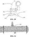
- FIG. 10 shows a deflector for a condenser according to another specific embodiment of the present disclosure.
- the deflecting structure has a trapezoidal section.
- the deflecting structure may include a first side plate 411, a second side plate 412, and a top plate 413.
- the top plate 413 faces directly toward the inlet 403, and the first side plate 411 and the second side plate 412 are of the same size and are symmetrically arranged on two sides of the top plate 413.
- the deflector having such a structure can also reduce the impact force of the gas flow from the compressor and reduce the noise level of the condenser.
- the deflector and the deflecting structure may be integrally formed.
- the deflecting structure may also be mounted on the deflector for a condenser as an additional component as long as the manufacturing or processing costs permit.
- the present disclosure provides a condenser including the above-mentioned deflector for a condenser. Because the deflector is disposed inside the condenser, the condenser is less likely to generate unexpected noise and vibration during running.
- the present disclosure further provides a refrigeration system including the above-mentioned condenser.
- the refrigeration system includes a cooling tower, a water chilling unit, a pumping device, etc. connected through pipelines.
- the water chilling unit consists of a compressor, a condenser, a throttle device, an evaporator, and the like.
- the condenser including the above-mentioned deflector can effectively achieve the objective of vibration and noise reduction without increasing the costs of the water chilling unit. Therefore, the above-mentioned condenser is suitable for use in various refrigeration systems.
- the deflector for a condenser the condenser including the deflector, and the refrigeration system equipped with the condenser of the present disclosure.
- These examples are only used for describing the principles and implementation manners of the present disclosure and are not intended to limit the scope of protection.
- Those of ordinary skill in the art can also make various modifications and improvements without departing from the scope of the present disclosure.
- the deflector may be made of steel or other high-strength materials.
Landscapes
- Engineering & Computer Science (AREA)
- Physics & Mathematics (AREA)
- Thermal Sciences (AREA)
- Mechanical Engineering (AREA)
- General Engineering & Computer Science (AREA)
- Heat-Exchange Devices With Radiators And Conduit Assemblies (AREA)
Applications Claiming Priority (1)
| Application Number | Priority Date | Filing Date | Title |
|---|---|---|---|
| CN201820068695.0U CN208332761U (zh) | 2018-01-16 | 2018-01-16 | 用于冷凝器的导流板、具有其的冷凝器及制冷系统 |
Publications (2)
| Publication Number | Publication Date |
|---|---|
| EP3511654A1 true EP3511654A1 (fr) | 2019-07-17 |
| EP3511654B1 EP3511654B1 (fr) | 2022-04-06 |
Family
ID=64788518
Family Applications (1)
| Application Number | Title | Priority Date | Filing Date |
|---|---|---|---|
| EP19151521.2A Active EP3511654B1 (fr) | 2018-01-16 | 2019-01-11 | Condensateur avec panneau de guidage et système de réfrigération |
Country Status (3)
| Country | Link |
|---|---|
| US (3) | US11098934B2 (fr) |
| EP (1) | EP3511654B1 (fr) |
| CN (1) | CN208332761U (fr) |
Families Citing this family (3)
| Publication number | Priority date | Publication date | Assignee | Title |
|---|---|---|---|---|
| CN208332761U (zh) | 2018-01-16 | 2019-01-04 | 开利公司 | 用于冷凝器的导流板、具有其的冷凝器及制冷系统 |
| KR20210036940A (ko) * | 2018-07-27 | 2021-04-05 | 요크 (우씨) 에어 컨디셔닝 앤드 리프리져레이션 씨오., 엘티디 | 응축기 |
| CN112304120B (zh) * | 2019-07-31 | 2022-08-02 | 中国石油天然气集团有限公司 | 换热器 |
Citations (3)
| Publication number | Priority date | Publication date | Assignee | Title |
|---|---|---|---|---|
| JPS59170697A (ja) * | 1983-03-18 | 1984-09-26 | Hitachi Ltd | 多管式熱交換器 |
| US20110024080A1 (en) * | 2009-07-29 | 2011-02-03 | Prodigy Energy Recovery Systems, Inc. | Heat Exchanger |
| CN202973672U (zh) * | 2012-11-06 | 2013-06-05 | 重庆美的通用制冷设备有限公司 | 壳管式冷凝器及制冷机组 |
Family Cites Families (29)
| Publication number | Priority date | Publication date | Assignee | Title |
|---|---|---|---|---|
| US2111570A (en) * | 1933-07-15 | 1938-03-22 | Baldwin Southwark Corp | Liquid control means for air conditioning apparatus |
| US2111133A (en) * | 1934-07-17 | 1938-03-15 | Baldwin Southwark Corp | Condensate entrainment means |
| US4194371A (en) * | 1976-08-13 | 1980-03-25 | Tecumseh Products Company | Refrigeration system with compressor mounted accumulator |
| US5122352A (en) * | 1988-03-08 | 1992-06-16 | Johnson Arthur F | Heat exchanger and pollutant removal system |
| US4928524A (en) * | 1988-07-22 | 1990-05-29 | Tokyo Keiso Co., Ltd. | Method and apparatus for measuring flow rate of a gas containing condensable components and mists |
| US5465783A (en) * | 1994-03-04 | 1995-11-14 | Fedco Automotive Components Company, Inc. | Sacrificial erosion bridge for a heat exchanger |
| US6668580B2 (en) * | 2002-04-16 | 2003-12-30 | Carrier Corporation | Chiller compressor circuit containing turning vanes |
| ITBS20020102A1 (it) | 2002-11-11 | 2004-05-12 | Turboden Srl | Gruppo di scambio termico integrato per turbine a vapore di fluido |
| US6968764B2 (en) * | 2003-08-21 | 2005-11-29 | J. E. Grote Company | Blade cleaner for a continuous loop blade on a food slicing machine |
| US20050115248A1 (en) * | 2003-10-29 | 2005-06-02 | Koehler Gregory J. | Liquefied natural gas structure |
| US6868695B1 (en) | 2004-04-13 | 2005-03-22 | American Standard International Inc. | Flow distributor and baffle system for a falling film evaporator |
| CN2739556Y (zh) * | 2004-10-18 | 2005-11-09 | 张凤岭 | 内埋双向多组壳管干式冷凝器 |
| CN2890783Y (zh) | 2006-03-24 | 2007-04-18 | 广州日立冷机有限公司 | 多壳程壳管式冷凝器 |
| WO2009089488A1 (fr) * | 2008-01-11 | 2009-07-16 | Johnson Controls Technology Company | Échangeur thermique |
| US8276653B2 (en) * | 2008-03-28 | 2012-10-02 | Saudi Arabian Oil Company | Raised overlapped impingement plate |
| EP2457051A2 (fr) | 2009-07-22 | 2012-05-30 | Johnson Controls Technology Company | Evaporateur compact pour refroidisseurs |
| CN202328931U (zh) | 2011-11-03 | 2012-07-11 | 上海瀚艺冷冻机械有限公司 | 带有过冷管的高能效干式壳管冷凝换热器 |
| EP2728155A1 (fr) * | 2012-11-06 | 2014-05-07 | BorgWarner Inc. | Dispositif d'échange de chaleur pour échanger de la chaleur entre des fluides |
| CN202928219U (zh) | 2012-12-11 | 2013-05-08 | 浙江国祥空调设备有限公司 | 一种高效水冷冷凝器 |
| CN203478730U (zh) | 2013-09-12 | 2014-03-12 | 西安交通大学 | 一种卧式管壳式水冷冷凝器 |
| CN104764258B (zh) | 2014-01-02 | 2017-08-11 | 约克(无锡)空调冷冻设备有限公司 | 壳管式冷凝器 |
| CN203964462U (zh) | 2014-04-25 | 2014-11-26 | 麦克维尔空调制冷(武汉)有限公司 | 一种冷凝器内置油分离器的冷水热泵机组 |
| CN104833140B (zh) | 2015-05-29 | 2017-03-08 | 珠海格力电器股份有限公司 | 一种换热设备及其回油式冷凝器 |
| CN205227950U (zh) | 2015-10-12 | 2016-05-11 | 珠海格力电器股份有限公司 | 一种油分离器以及包括该油分离器的冷凝器 |
| CN106642833A (zh) | 2015-11-04 | 2017-05-10 | 麦克维尔空调制冷(武汉)有限公司 | 冷凝器以及包含该冷凝器的换热系统 |
| CN105823353A (zh) | 2016-03-23 | 2016-08-03 | 东华大学 | 一种高效冷凝器 |
| CN206073517U (zh) | 2016-08-31 | 2017-04-05 | 广州捷邦节能设备制造有限公司 | 管壳式冷凝器用导流板 |
| CN107062709A (zh) | 2017-05-22 | 2017-08-18 | 珠海格力电器股份有限公司 | 冷凝器和制冷系统 |
| CN208332761U (zh) | 2018-01-16 | 2019-01-04 | 开利公司 | 用于冷凝器的导流板、具有其的冷凝器及制冷系统 |
-
2018
- 2018-01-16 CN CN201820068695.0U patent/CN208332761U/zh active Active
-
2019
- 2019-01-11 EP EP19151521.2A patent/EP3511654B1/fr active Active
- 2019-01-16 US US16/249,117 patent/US11098934B2/en active Active
-
2021
- 2021-04-21 US US17/236,414 patent/US11821665B2/en active Active
-
2023
- 2023-10-09 US US18/483,290 patent/US20240035720A1/en active Pending
Patent Citations (3)
| Publication number | Priority date | Publication date | Assignee | Title |
|---|---|---|---|---|
| JPS59170697A (ja) * | 1983-03-18 | 1984-09-26 | Hitachi Ltd | 多管式熱交換器 |
| US20110024080A1 (en) * | 2009-07-29 | 2011-02-03 | Prodigy Energy Recovery Systems, Inc. | Heat Exchanger |
| CN202973672U (zh) * | 2012-11-06 | 2013-06-05 | 重庆美的通用制冷设备有限公司 | 壳管式冷凝器及制冷机组 |
Also Published As
| Publication number | Publication date |
|---|---|
| EP3511654B1 (fr) | 2022-04-06 |
| CN208332761U (zh) | 2019-01-04 |
| US11098934B2 (en) | 2021-08-24 |
| US11821665B2 (en) | 2023-11-21 |
| US20210239372A1 (en) | 2021-08-05 |
| US20240035720A1 (en) | 2024-02-01 |
| US20190219314A1 (en) | 2019-07-18 |
Similar Documents
| Publication | Publication Date | Title |
|---|---|---|
| US11821665B2 (en) | Guiding panel for condenser, condenser and refrigeration system | |
| US9890977B2 (en) | Flash tank economizer for two stage centrifugal water chillers | |
| JP2013096622A (ja) | 空気調和装置の室外ユニット | |
| RU2644961C1 (ru) | Холодильник | |
| JP2006266636A (ja) | 冷凍装置 | |
| US5875643A (en) | Refrigeration cycle capacity enhancement apparatus | |
| EP2693138B1 (fr) | Refroidisseur centrifuge | |
| EP4105576B1 (fr) | Économiseur pour système de réfrigération et système de réfrigération | |
| CN215114057U (zh) | 一种新型喷淋式蒸发冷却换热器 | |
| CN104848454B (zh) | 房车空调器的水路结构及房车空调器 | |
| CN103836853B (zh) | 一种气液分离器及具有其的空调系统 | |
| JP3277634B2 (ja) | タ−ボ冷凍機 | |
| EP4092359A1 (fr) | Déflecteur pour condenseur, condenseur le comportant et système de refroidissement | |
| CN108237871B (zh) | 一种车载式人体微环境降温系统制冷主机 | |
| CN212414382U (zh) | 一种具有结构底板的海鲜机 | |
| CN210951948U (zh) | 一种超薄型增强式商超冷暖机 | |
| CN204665546U (zh) | 房车空调器的水路结构及房车空调器 | |
| CN218936508U (zh) | 空调器室外机 | |
| CN212414383U (zh) | 一种具有导流底板的海鲜机 | |
| CN221099058U (zh) | 气液分离器、压缩机及空调器 | |
| CN105485984B (zh) | 空调的气液分离器及制冷时对室内机降噪的方法 | |
| EP3839399A1 (fr) | Échangeur de chaleur à calandre et système de climatisation d'air | |
| CN218821086U (zh) | 一种基于风冷冰箱的新型双蒸发器制冷系统 | |
| CN219014474U (zh) | 移动空调 | |
| CN212414384U (zh) | 一种海鲜机 |
Legal Events
| Date | Code | Title | Description |
|---|---|---|---|
| PUAI | Public reference made under article 153(3) epc to a published international application that has entered the european phase |
Free format text: ORIGINAL CODE: 0009012 |
|
| STAA | Information on the status of an ep patent application or granted ep patent |
Free format text: STATUS: THE APPLICATION HAS BEEN PUBLISHED |
|
| AK | Designated contracting states |
Kind code of ref document: A1 Designated state(s): AL AT BE BG CH CY CZ DE DK EE ES FI FR GB GR HR HU IE IS IT LI LT LU LV MC MK MT NL NO PL PT RO RS SE SI SK SM TR |
|
| AX | Request for extension of the european patent |
Extension state: BA ME |
|
| STAA | Information on the status of an ep patent application or granted ep patent |
Free format text: STATUS: REQUEST FOR EXAMINATION WAS MADE |
|
| 17P | Request for examination filed |
Effective date: 20200117 |
|
| RBV | Designated contracting states (corrected) |
Designated state(s): AL AT BE BG CH CY CZ DE DK EE ES FI FR GB GR HR HU IE IS IT LI LT LU LV MC MK MT NL NO PL PT RO RS SE SI SK SM TR |
|
| GRAP | Despatch of communication of intention to grant a patent |
Free format text: ORIGINAL CODE: EPIDOSNIGR1 |
|
| STAA | Information on the status of an ep patent application or granted ep patent |
Free format text: STATUS: GRANT OF PATENT IS INTENDED |
|
| INTG | Intention to grant announced |
Effective date: 20220103 |
|
| GRAS | Grant fee paid |
Free format text: ORIGINAL CODE: EPIDOSNIGR3 |
|
| GRAA | (expected) grant |
Free format text: ORIGINAL CODE: 0009210 |
|
| STAA | Information on the status of an ep patent application or granted ep patent |
Free format text: STATUS: THE PATENT HAS BEEN GRANTED |
|
| AK | Designated contracting states |
Kind code of ref document: B1 Designated state(s): AL AT BE BG CH CY CZ DE DK EE ES FI FR GB GR HR HU IE IS IT LI LT LU LV MC MK MT NL NO PL PT RO RS SE SI SK SM TR |
|
| REG | Reference to a national code |
Ref country code: GB Ref legal event code: FG4D |
|
| REG | Reference to a national code |
Ref country code: CH Ref legal event code: EP |
|
| REG | Reference to a national code |
Ref country code: AT Ref legal event code: REF Ref document number: 1481690 Country of ref document: AT Kind code of ref document: T Effective date: 20220415 |
|
| REG | Reference to a national code |
Ref country code: DE Ref legal event code: R096 Ref document number: 602019013227 Country of ref document: DE |
|
| REG | Reference to a national code |
Ref country code: IE Ref legal event code: FG4D |
|
| REG | Reference to a national code |
Ref country code: SE Ref legal event code: TRGR |
|
| REG | Reference to a national code |
Ref country code: LT Ref legal event code: MG9D |
|
| REG | Reference to a national code |
Ref country code: NL Ref legal event code: MP Effective date: 20220406 |
|
| REG | Reference to a national code |
Ref country code: AT Ref legal event code: MK05 Ref document number: 1481690 Country of ref document: AT Kind code of ref document: T Effective date: 20220406 |
|
| PG25 | Lapsed in a contracting state [announced via postgrant information from national office to epo] |
Ref country code: NL Free format text: LAPSE BECAUSE OF FAILURE TO SUBMIT A TRANSLATION OF THE DESCRIPTION OR TO PAY THE FEE WITHIN THE PRESCRIBED TIME-LIMIT Effective date: 20220406 |
|
| PG25 | Lapsed in a contracting state [announced via postgrant information from national office to epo] |
Ref country code: PT Free format text: LAPSE BECAUSE OF FAILURE TO SUBMIT A TRANSLATION OF THE DESCRIPTION OR TO PAY THE FEE WITHIN THE PRESCRIBED TIME-LIMIT Effective date: 20220808 Ref country code: NO Free format text: LAPSE BECAUSE OF FAILURE TO SUBMIT A TRANSLATION OF THE DESCRIPTION OR TO PAY THE FEE WITHIN THE PRESCRIBED TIME-LIMIT Effective date: 20220706 Ref country code: LT Free format text: LAPSE BECAUSE OF FAILURE TO SUBMIT A TRANSLATION OF THE DESCRIPTION OR TO PAY THE FEE WITHIN THE PRESCRIBED TIME-LIMIT Effective date: 20220406 Ref country code: HR Free format text: LAPSE BECAUSE OF FAILURE TO SUBMIT A TRANSLATION OF THE DESCRIPTION OR TO PAY THE FEE WITHIN THE PRESCRIBED TIME-LIMIT Effective date: 20220406 Ref country code: GR Free format text: LAPSE BECAUSE OF FAILURE TO SUBMIT A TRANSLATION OF THE DESCRIPTION OR TO PAY THE FEE WITHIN THE PRESCRIBED TIME-LIMIT Effective date: 20220707 Ref country code: FI Free format text: LAPSE BECAUSE OF FAILURE TO SUBMIT A TRANSLATION OF THE DESCRIPTION OR TO PAY THE FEE WITHIN THE PRESCRIBED TIME-LIMIT Effective date: 20220406 Ref country code: ES Free format text: LAPSE BECAUSE OF FAILURE TO SUBMIT A TRANSLATION OF THE DESCRIPTION OR TO PAY THE FEE WITHIN THE PRESCRIBED TIME-LIMIT Effective date: 20220406 Ref country code: BG Free format text: LAPSE BECAUSE OF FAILURE TO SUBMIT A TRANSLATION OF THE DESCRIPTION OR TO PAY THE FEE WITHIN THE PRESCRIBED TIME-LIMIT Effective date: 20220706 Ref country code: AT Free format text: LAPSE BECAUSE OF FAILURE TO SUBMIT A TRANSLATION OF THE DESCRIPTION OR TO PAY THE FEE WITHIN THE PRESCRIBED TIME-LIMIT Effective date: 20220406 |
|
| PG25 | Lapsed in a contracting state [announced via postgrant information from national office to epo] |
Ref country code: RS Free format text: LAPSE BECAUSE OF FAILURE TO SUBMIT A TRANSLATION OF THE DESCRIPTION OR TO PAY THE FEE WITHIN THE PRESCRIBED TIME-LIMIT Effective date: 20220406 Ref country code: PL Free format text: LAPSE BECAUSE OF FAILURE TO SUBMIT A TRANSLATION OF THE DESCRIPTION OR TO PAY THE FEE WITHIN THE PRESCRIBED TIME-LIMIT Effective date: 20220406 Ref country code: LV Free format text: LAPSE BECAUSE OF FAILURE TO SUBMIT A TRANSLATION OF THE DESCRIPTION OR TO PAY THE FEE WITHIN THE PRESCRIBED TIME-LIMIT Effective date: 20220406 Ref country code: IS Free format text: LAPSE BECAUSE OF FAILURE TO SUBMIT A TRANSLATION OF THE DESCRIPTION OR TO PAY THE FEE WITHIN THE PRESCRIBED TIME-LIMIT Effective date: 20220806 |
|
| REG | Reference to a national code |
Ref country code: DE Ref legal event code: R097 Ref document number: 602019013227 Country of ref document: DE |
|
| PG25 | Lapsed in a contracting state [announced via postgrant information from national office to epo] |
Ref country code: SM Free format text: LAPSE BECAUSE OF FAILURE TO SUBMIT A TRANSLATION OF THE DESCRIPTION OR TO PAY THE FEE WITHIN THE PRESCRIBED TIME-LIMIT Effective date: 20220406 Ref country code: SK Free format text: LAPSE BECAUSE OF FAILURE TO SUBMIT A TRANSLATION OF THE DESCRIPTION OR TO PAY THE FEE WITHIN THE PRESCRIBED TIME-LIMIT Effective date: 20220406 Ref country code: RO Free format text: LAPSE BECAUSE OF FAILURE TO SUBMIT A TRANSLATION OF THE DESCRIPTION OR TO PAY THE FEE WITHIN THE PRESCRIBED TIME-LIMIT Effective date: 20220406 Ref country code: EE Free format text: LAPSE BECAUSE OF FAILURE TO SUBMIT A TRANSLATION OF THE DESCRIPTION OR TO PAY THE FEE WITHIN THE PRESCRIBED TIME-LIMIT Effective date: 20220406 Ref country code: DK Free format text: LAPSE BECAUSE OF FAILURE TO SUBMIT A TRANSLATION OF THE DESCRIPTION OR TO PAY THE FEE WITHIN THE PRESCRIBED TIME-LIMIT Effective date: 20220406 Ref country code: CZ Free format text: LAPSE BECAUSE OF FAILURE TO SUBMIT A TRANSLATION OF THE DESCRIPTION OR TO PAY THE FEE WITHIN THE PRESCRIBED TIME-LIMIT Effective date: 20220406 |
|
| PLBE | No opposition filed within time limit |
Free format text: ORIGINAL CODE: 0009261 |
|
| STAA | Information on the status of an ep patent application or granted ep patent |
Free format text: STATUS: NO OPPOSITION FILED WITHIN TIME LIMIT |
|
| 26N | No opposition filed |
Effective date: 20230110 |
|
| PG25 | Lapsed in a contracting state [announced via postgrant information from national office to epo] |
Ref country code: AL Free format text: LAPSE BECAUSE OF FAILURE TO SUBMIT A TRANSLATION OF THE DESCRIPTION OR TO PAY THE FEE WITHIN THE PRESCRIBED TIME-LIMIT Effective date: 20220406 |
|
| PG25 | Lapsed in a contracting state [announced via postgrant information from national office to epo] |
Ref country code: SI Free format text: LAPSE BECAUSE OF FAILURE TO SUBMIT A TRANSLATION OF THE DESCRIPTION OR TO PAY THE FEE WITHIN THE PRESCRIBED TIME-LIMIT Effective date: 20220406 |
|
| P01 | Opt-out of the competence of the unified patent court (upc) registered |
Effective date: 20230527 |
|
| GBPC | Gb: european patent ceased through non-payment of renewal fee |
Effective date: 20230111 |
|
| PG25 | Lapsed in a contracting state [announced via postgrant information from national office to epo] |
Ref country code: LU Free format text: LAPSE BECAUSE OF NON-PAYMENT OF DUE FEES Effective date: 20230111 |
|
| REG | Reference to a national code |
Ref country code: BE Ref legal event code: MM Effective date: 20230131 |
|
| PG25 | Lapsed in a contracting state [announced via postgrant information from national office to epo] |
Ref country code: GB Free format text: LAPSE BECAUSE OF NON-PAYMENT OF DUE FEES Effective date: 20230111 |
|
| PG25 | Lapsed in a contracting state [announced via postgrant information from national office to epo] |
Ref country code: BE Free format text: LAPSE BECAUSE OF NON-PAYMENT OF DUE FEES Effective date: 20230131 |
|
| PG25 | Lapsed in a contracting state [announced via postgrant information from national office to epo] |
Ref country code: IT Free format text: LAPSE BECAUSE OF FAILURE TO SUBMIT A TRANSLATION OF THE DESCRIPTION OR TO PAY THE FEE WITHIN THE PRESCRIBED TIME-LIMIT Effective date: 20220406 Ref country code: IE Free format text: LAPSE BECAUSE OF NON-PAYMENT OF DUE FEES Effective date: 20230111 |
|
| PGFP | Annual fee paid to national office [announced via postgrant information from national office to epo] |
Ref country code: SE Payment date: 20231219 Year of fee payment: 6 Ref country code: FR Payment date: 20231219 Year of fee payment: 6 |
|
| PGFP | Annual fee paid to national office [announced via postgrant information from national office to epo] |
Ref country code: DE Payment date: 20231219 Year of fee payment: 6 Ref country code: CH Payment date: 20240202 Year of fee payment: 6 |