EP3511430A1 - Method for a continuous heat treatment of a steel strip, and installation for dip coating a steel strip - Google Patents
Method for a continuous heat treatment of a steel strip, and installation for dip coating a steel strip Download PDFInfo
- Publication number
- EP3511430A1 EP3511430A1 EP19151613.7A EP19151613A EP3511430A1 EP 3511430 A1 EP3511430 A1 EP 3511430A1 EP 19151613 A EP19151613 A EP 19151613A EP 3511430 A1 EP3511430 A1 EP 3511430A1
- Authority
- EP
- European Patent Office
- Prior art keywords
- steel strip
- seconds
- chamber
- inductor
- atmosphere
- Prior art date
- Legal status (The legal status is an assumption and is not a legal conclusion. Google has not performed a legal analysis and makes no representation as to the accuracy of the status listed.)
- Pending
Links
- 229910000831 Steel Inorganic materials 0.000 title claims abstract description 190
- 239000010959 steel Substances 0.000 title claims abstract description 190
- 238000010438 heat treatment Methods 0.000 title claims abstract description 98
- 238000000034 method Methods 0.000 title claims abstract description 58
- 238000003618 dip coating Methods 0.000 title claims abstract description 8
- 238000009434 installation Methods 0.000 title 1
- 238000007254 oxidation reaction Methods 0.000 claims abstract description 45
- 230000003647 oxidation Effects 0.000 claims abstract description 44
- 238000001816 cooling Methods 0.000 claims abstract description 35
- 239000011248 coating agent Substances 0.000 claims abstract description 19
- 238000000576 coating method Methods 0.000 claims abstract description 19
- 238000000638 solvent extraction Methods 0.000 claims abstract description 12
- 238000011144 upstream manufacturing Methods 0.000 claims abstract description 7
- 229910052739 hydrogen Inorganic materials 0.000 claims description 39
- 239000001257 hydrogen Substances 0.000 claims description 37
- UFHFLCQGNIYNRP-UHFFFAOYSA-N Hydrogen Chemical compound [H][H] UFHFLCQGNIYNRP-UHFFFAOYSA-N 0.000 claims description 27
- IJGRMHOSHXDMSA-UHFFFAOYSA-N Atomic nitrogen Chemical compound N#N IJGRMHOSHXDMSA-UHFFFAOYSA-N 0.000 claims description 25
- 238000010583 slow cooling Methods 0.000 claims description 16
- 150000002431 hydrogen Chemical class 0.000 claims description 14
- 229910052760 oxygen Inorganic materials 0.000 claims description 7
- 229910052725 zinc Inorganic materials 0.000 claims description 7
- 239000011701 zinc Substances 0.000 claims description 7
- UQSXHKLRYXJYBZ-UHFFFAOYSA-N Iron oxide Chemical compound [Fe]=O UQSXHKLRYXJYBZ-UHFFFAOYSA-N 0.000 claims description 6
- HCHKCACWOHOZIP-UHFFFAOYSA-N Zinc Chemical compound [Zn] HCHKCACWOHOZIP-UHFFFAOYSA-N 0.000 claims description 6
- QVGXLLKOCUKJST-UHFFFAOYSA-N atomic oxygen Chemical compound [O] QVGXLLKOCUKJST-UHFFFAOYSA-N 0.000 claims description 4
- 239000001301 oxygen Substances 0.000 claims description 4
- XLYOFNOQVPJJNP-UHFFFAOYSA-N water Chemical compound O XLYOFNOQVPJJNP-UHFFFAOYSA-N 0.000 claims description 3
- 230000001590 oxidative effect Effects 0.000 claims description 2
- 230000007812 deficiency Effects 0.000 claims 1
- 238000010586 diagram Methods 0.000 description 10
- 229910052757 nitrogen Inorganic materials 0.000 description 6
- XEEYBQQBJWHFJM-UHFFFAOYSA-N Iron Chemical compound [Fe] XEEYBQQBJWHFJM-UHFFFAOYSA-N 0.000 description 5
- 229910001566 austenite Inorganic materials 0.000 description 4
- 230000008901 benefit Effects 0.000 description 4
- 239000007789 gas Substances 0.000 description 4
- 239000000463 material Substances 0.000 description 4
- 238000005275 alloying Methods 0.000 description 3
- 238000007598 dipping method Methods 0.000 description 3
- 230000008859 change Effects 0.000 description 2
- 238000011049 filling Methods 0.000 description 2
- 238000005246 galvanizing Methods 0.000 description 2
- 230000001939 inductive effect Effects 0.000 description 2
- 238000003754 machining Methods 0.000 description 2
- 238000004519 manufacturing process Methods 0.000 description 2
- 239000002184 metal Substances 0.000 description 2
- 229910052751 metal Inorganic materials 0.000 description 2
- 230000008569 process Effects 0.000 description 2
- 230000005855 radiation Effects 0.000 description 2
- 230000009467 reduction Effects 0.000 description 2
- 238000004904 shortening Methods 0.000 description 2
- 229910000859 α-Fe Inorganic materials 0.000 description 2
- 229910045601 alloy Inorganic materials 0.000 description 1
- 239000000956 alloy Substances 0.000 description 1
- 238000000137 annealing Methods 0.000 description 1
- 238000006243 chemical reaction Methods 0.000 description 1
- 238000002485 combustion reaction Methods 0.000 description 1
- 230000002860 competitive effect Effects 0.000 description 1
- 230000001419 dependent effect Effects 0.000 description 1
- 238000011161 development Methods 0.000 description 1
- 230000018109 developmental process Effects 0.000 description 1
- 238000009792 diffusion process Methods 0.000 description 1
- 239000011261 inert gas Substances 0.000 description 1
- 229910052742 iron Inorganic materials 0.000 description 1
- 239000007788 liquid Substances 0.000 description 1
- 230000004048 modification Effects 0.000 description 1
- 238000012986 modification Methods 0.000 description 1
- 238000002360 preparation method Methods 0.000 description 1
- 238000003303 reheating Methods 0.000 description 1
- 230000001629 suppression Effects 0.000 description 1
- 238000003856 thermoforming Methods 0.000 description 1
- 230000001052 transient effect Effects 0.000 description 1
- 238000010792 warming Methods 0.000 description 1
- 150000003751 zinc Chemical class 0.000 description 1
Images


Classifications
-
- C—CHEMISTRY; METALLURGY
- C21—METALLURGY OF IRON
- C21D—MODIFYING THE PHYSICAL STRUCTURE OF FERROUS METALS; GENERAL DEVICES FOR HEAT TREATMENT OF FERROUS OR NON-FERROUS METALS OR ALLOYS; MAKING METAL MALLEABLE, e.g. BY DECARBURISATION OR TEMPERING
- C21D9/00—Heat treatment, e.g. annealing, hardening, quenching or tempering, adapted for particular articles; Furnaces therefor
- C21D9/52—Heat treatment, e.g. annealing, hardening, quenching or tempering, adapted for particular articles; Furnaces therefor for wires; for strips ; for rods of unlimited length
- C21D9/54—Furnaces for treating strips or wire
- C21D9/56—Continuous furnaces for strip or wire
- C21D9/561—Continuous furnaces for strip or wire with a controlled atmosphere or vacuum
-
- C—CHEMISTRY; METALLURGY
- C21—METALLURGY OF IRON
- C21D—MODIFYING THE PHYSICAL STRUCTURE OF FERROUS METALS; GENERAL DEVICES FOR HEAT TREATMENT OF FERROUS OR NON-FERROUS METALS OR ALLOYS; MAKING METAL MALLEABLE, e.g. BY DECARBURISATION OR TEMPERING
- C21D9/00—Heat treatment, e.g. annealing, hardening, quenching or tempering, adapted for particular articles; Furnaces therefor
- C21D9/52—Heat treatment, e.g. annealing, hardening, quenching or tempering, adapted for particular articles; Furnaces therefor for wires; for strips ; for rods of unlimited length
- C21D9/54—Furnaces for treating strips or wire
- C21D9/56—Continuous furnaces for strip or wire
- C21D9/573—Continuous furnaces for strip or wire with cooling
-
- C—CHEMISTRY; METALLURGY
- C23—COATING METALLIC MATERIAL; COATING MATERIAL WITH METALLIC MATERIAL; CHEMICAL SURFACE TREATMENT; DIFFUSION TREATMENT OF METALLIC MATERIAL; COATING BY VACUUM EVAPORATION, BY SPUTTERING, BY ION IMPLANTATION OR BY CHEMICAL VAPOUR DEPOSITION, IN GENERAL; INHIBITING CORROSION OF METALLIC MATERIAL OR INCRUSTATION IN GENERAL
- C23C—COATING METALLIC MATERIAL; COATING MATERIAL WITH METALLIC MATERIAL; SURFACE TREATMENT OF METALLIC MATERIAL BY DIFFUSION INTO THE SURFACE, BY CHEMICAL CONVERSION OR SUBSTITUTION; COATING BY VACUUM EVAPORATION, BY SPUTTERING, BY ION IMPLANTATION OR BY CHEMICAL VAPOUR DEPOSITION, IN GENERAL
- C23C2/00—Hot-dipping or immersion processes for applying the coating material in the molten state without affecting the shape; Apparatus therefor
- C23C2/003—Apparatus
- C23C2/0038—Apparatus characterised by the pre-treatment chambers located immediately upstream of the bath or occurring locally before the dipping process
-
- C—CHEMISTRY; METALLURGY
- C23—COATING METALLIC MATERIAL; COATING MATERIAL WITH METALLIC MATERIAL; CHEMICAL SURFACE TREATMENT; DIFFUSION TREATMENT OF METALLIC MATERIAL; COATING BY VACUUM EVAPORATION, BY SPUTTERING, BY ION IMPLANTATION OR BY CHEMICAL VAPOUR DEPOSITION, IN GENERAL; INHIBITING CORROSION OF METALLIC MATERIAL OR INCRUSTATION IN GENERAL
- C23C—COATING METALLIC MATERIAL; COATING MATERIAL WITH METALLIC MATERIAL; SURFACE TREATMENT OF METALLIC MATERIAL BY DIFFUSION INTO THE SURFACE, BY CHEMICAL CONVERSION OR SUBSTITUTION; COATING BY VACUUM EVAPORATION, BY SPUTTERING, BY ION IMPLANTATION OR BY CHEMICAL VAPOUR DEPOSITION, IN GENERAL
- C23C2/00—Hot-dipping or immersion processes for applying the coating material in the molten state without affecting the shape; Apparatus therefor
- C23C2/02—Pretreatment of the material to be coated, e.g. for coating on selected surface areas
- C23C2/022—Pretreatment of the material to be coated, e.g. for coating on selected surface areas by heating
- C23C2/0224—Two or more thermal pretreatments
-
- C—CHEMISTRY; METALLURGY
- C23—COATING METALLIC MATERIAL; COATING MATERIAL WITH METALLIC MATERIAL; CHEMICAL SURFACE TREATMENT; DIFFUSION TREATMENT OF METALLIC MATERIAL; COATING BY VACUUM EVAPORATION, BY SPUTTERING, BY ION IMPLANTATION OR BY CHEMICAL VAPOUR DEPOSITION, IN GENERAL; INHIBITING CORROSION OF METALLIC MATERIAL OR INCRUSTATION IN GENERAL
- C23C—COATING METALLIC MATERIAL; COATING MATERIAL WITH METALLIC MATERIAL; SURFACE TREATMENT OF METALLIC MATERIAL BY DIFFUSION INTO THE SURFACE, BY CHEMICAL CONVERSION OR SUBSTITUTION; COATING BY VACUUM EVAPORATION, BY SPUTTERING, BY ION IMPLANTATION OR BY CHEMICAL VAPOUR DEPOSITION, IN GENERAL
- C23C2/00—Hot-dipping or immersion processes for applying the coating material in the molten state without affecting the shape; Apparatus therefor
- C23C2/04—Hot-dipping or immersion processes for applying the coating material in the molten state without affecting the shape; Apparatus therefor characterised by the coating material
- C23C2/06—Zinc or cadmium or alloys based thereon
-
- C—CHEMISTRY; METALLURGY
- C23—COATING METALLIC MATERIAL; COATING MATERIAL WITH METALLIC MATERIAL; CHEMICAL SURFACE TREATMENT; DIFFUSION TREATMENT OF METALLIC MATERIAL; COATING BY VACUUM EVAPORATION, BY SPUTTERING, BY ION IMPLANTATION OR BY CHEMICAL VAPOUR DEPOSITION, IN GENERAL; INHIBITING CORROSION OF METALLIC MATERIAL OR INCRUSTATION IN GENERAL
- C23C—COATING METALLIC MATERIAL; COATING MATERIAL WITH METALLIC MATERIAL; SURFACE TREATMENT OF METALLIC MATERIAL BY DIFFUSION INTO THE SURFACE, BY CHEMICAL CONVERSION OR SUBSTITUTION; COATING BY VACUUM EVAPORATION, BY SPUTTERING, BY ION IMPLANTATION OR BY CHEMICAL VAPOUR DEPOSITION, IN GENERAL
- C23C2/00—Hot-dipping or immersion processes for applying the coating material in the molten state without affecting the shape; Apparatus therefor
- C23C2/34—Hot-dipping or immersion processes for applying the coating material in the molten state without affecting the shape; Apparatus therefor characterised by the shape of the material to be treated
- C23C2/36—Elongated material
- C23C2/40—Plates; Strips
-
- F—MECHANICAL ENGINEERING; LIGHTING; HEATING; WEAPONS; BLASTING
- F27—FURNACES; KILNS; OVENS; RETORTS
- F27B—FURNACES, KILNS, OVENS, OR RETORTS IN GENERAL; OPEN SINTERING OR LIKE APPARATUS
- F27B9/00—Furnaces through which the charge is moved mechanically, e.g. of tunnel type; Similar furnaces in which the charge moves by gravity
- F27B9/02—Furnaces through which the charge is moved mechanically, e.g. of tunnel type; Similar furnaces in which the charge moves by gravity of multiple-track type; of multiple-chamber type; Combinations of furnaces
- F27B9/028—Multi-chamber type furnaces
-
- F—MECHANICAL ENGINEERING; LIGHTING; HEATING; WEAPONS; BLASTING
- F27—FURNACES; KILNS; OVENS; RETORTS
- F27B—FURNACES, KILNS, OVENS, OR RETORTS IN GENERAL; OPEN SINTERING OR LIKE APPARATUS
- F27B9/00—Furnaces through which the charge is moved mechanically, e.g. of tunnel type; Similar furnaces in which the charge moves by gravity
- F27B9/04—Furnaces through which the charge is moved mechanically, e.g. of tunnel type; Similar furnaces in which the charge moves by gravity adapted for treating the charge in vacuum or special atmosphere
- F27B9/045—Furnaces with controlled atmosphere
Definitions
- the invention relates to a method for a continuous heat treatment of a steel strip according to the preamble of claim 1 or to the preamble of claim 7, and a plant for hot dip coating a steel strip of high-strength grade, which is moved in a transport direction.
- the state of the art as a countermeasure known as the pre-oxidation, in which a coverage of these oxides by a FeO layer and a subsequent reduction to iron (Fe) takes place.
- This creates on or on the surface To a coated steel strip a pure Fe layer, whereupon a metallic coating adheres well.
- some materials tend to fail adhesion at a greater depth because the selectively formed oxides such as MnO and others produce a passive layer on which the adhesion of the pure Fe layer is poor.
- EP 1 819 840 B1 and EP 2 732 062 B1 each disclose a method and apparatus for hot dip coating a strip of higher strength steel, as well as a method for continuous heat treatment of a steel strip according to the preamble of claim 1 of the present patent application
- the object of the invention is to suppress the selective oxidation to the extent that these oxides do not interfere with the subsequent application of a metallic coating to a surface of the steel strip in order to prepare a coating of steel strips.
- a coating device can be provided for step c) or vi) which, viewed in the transport direction of the steel strip, is arranged downstream of a furnace device.
- PVD P hysical V apor D eposition
- RTF Radiant Tube Furnace
- the invention likewise provides a system for hot-dip coating of a steel strip of high-strength quality moving in a transport direction, in particular of oxidation-sensitive AHSS grades.
- a plant comprises a hot dip bath into which the steel strip is immersed for coating can be, wherein - seen in the transport direction of the steel strip - upstream of the Schmelztauchbad at least a first heating chamber with at least one inductor, preferably in the form of a transverse field inductor, a rapid cooling chamber and a holding chamber for a partitioning of the steel strip are arranged.
- an inductor and / or in the outlet region of the holding chamber, a further inductor may be provided in the inlet region of the holding chamber or upstream thereof.
- the invention is based on the essential finding that the strip heating or the heating of the steel strip to a temperature of up to 950 ° C takes place as quickly as possible, the subsequent holding or dwell time for the steel strip has to be small at a predetermined temperature.
- the temperature to which the steel strip in step a) or in step iv) is heated and preferably maintained below 950 ° C and, for example, a value of 945 ° C, 940 ° C, 935 ° C, 930 ° C, 925 ° C or 920 ° C.
- this temperature, to which the steel strip is heated and preferably also held in step a) or in step iv) assumes a value which lies between the example values just mentioned, and for example a value of 942 ° C or other intermediate values.
- the residence time of the steel strip> 750 ° C must be as short as possible.
- the heating of the steel strip to a temperature of up to 950 ° C has shown that with an atmosphere having at least a proportion of 20% hydrogen, preferably nitrogen, and a dew point of less than or less than -40 ° C residence times for the steel strip are allowed up to a maximum of 180 seconds. Depending on the nature of the steel strip to be coated, these residence times may also be shorter than 180 seconds.
- the material of the steel strip is partially or completely converted into austenite during the holding or residence time.
- rapid cooling is carried out for the steel strip under a hydrogen-containing atmosphere at ⁇ 500 ° C., as defined in step a) or in step v).
- the cooling rate can be at least 40 K / s, for which a high hydrogen content is expedient.
- a hydrogen-rich inert gas with a proportion of e.g. 50% hydrogen used in the heating part and / or in the slow cooling to avoid oxidation is expedient.
- DFF Direct Fired Furnace
- step a) the steel strip is heated by at least one inductor, preferably in the form of a transverse field inductor, to the holding temperature of up to 950 ° C. This makes it possible to achieve a rapid heating for the steel strip with a heating rate of at least 50 K / s.
- step a) the steel strip is inductively heated in two stages, the steel strip by a first inductor, preferably in the form of a longitudinal field inductor, initially to a temperature of up to 720 ° C is heated and then heated by a second inductor, preferably in the form of a transverse field inductor, to the holding temperature of up to 950 ° C.
- a first inductor preferably in the form of a longitudinal field inductor
- a second inductor preferably in the form of a transverse field inductor
- the residence time in the first-mentioned process according to the invention in step a) can also be less than 180 seconds.
- this residence time in the context of the present invention also ⁇ 170 seconds, preferably ⁇ 160 seconds, more preferably ⁇ 150 seconds, more preferably ⁇ 140 seconds, more preferably ⁇ 130 seconds, more preferably ⁇ 120 seconds, more preferably ⁇ 110 seconds, more preferably ⁇ 100 seconds, more preferably ⁇ 90 seconds, more preferably ⁇ 85 seconds, more preferably ⁇ 80 seconds, more preferably ⁇ 75 seconds, more preferably ⁇ 70 seconds, further preferably ⁇ 65 seconds, further preferably ⁇ 60 seconds , more preferably ⁇ 55 seconds, more preferably ⁇ 50 seconds, more preferably ⁇ 45 seconds, further preferably ⁇ 40 seconds, further preferably ⁇ 35 Seconds, more preferably ⁇ 30 seconds, more preferably ⁇ 25 seconds, more preferably ⁇ 20 seconds, more preferably ⁇ 15 seconds, more preferably ⁇ 10 seconds, more
- the steel strip is cooled in the rapid cooling in step b) or in step v) to a temperature which is in a range between 200 ° C and 450 ° C.
- a slow cooling is performed for the steel strip.
- such slow cooling takes place between steps a) and b), whereby in the case of the second-mentioned method according to the invention, such slow cooling takes place between steps iv) and v).
- a hydrogen-containing atmosphere which, for example, contains at least 20% hydrogen and may have a dew point of ⁇ -40 ° C.
- this atmosphere in addition to the hydrogen content then contains residual nitrogen.
- the time of slow cooling with respect to the oxidation of Si is part of the above-mentioned residence time.
- further process steps may be provided for the continuous heat treatment of the steel strip, which may be e.g. may be a reheating and / or a holding of the steel strip.
- These possible further process steps are driven at temperatures of> 600 ° C and are therefore irrelevant with regard to the oxidation of Si.
- a high hydrogen content is not required in this case, it is not disadvantageous, so that it is basically possible to drive for these further process steps in the same atmosphere as the preceding rapid cooling.
- FIG. 1 to 12 Preferred embodiment of a method according to the invention for a continuous heat treatment of a steel strip 102 and a system 10 according to the invention explained. Identical features in the drawing are each provided with the same reference numerals. At this point, it should be noted separately that the drawing is merely simplified and shown in particular without scale.
- Fig. 1 shows the system 10 simplified in principle in a side view thereof.
- This plant 10 is a continuous hot dip galvanizing line (CGL), with which a steel strip 102 is subjected to a heat treatment in various steps or chambers, followed by at least one surface of the steel strip, preferably all surfaces thereof, in one Hot-dip bath 104, in the Fig. 1 denoted by "zinc pot", a metallic coating is applied, preferably in the form of a zinc layer. Accordingly, the hot dip bath 104 is filled with liquid zinc.
- CGL continuous hot dip galvanizing line
- the chambers 1-6 are referred to hereinafter as the first to six-sixth chamber according to these numbers.
- the principle simplified side view according to Fig. 1 illustrates that the steel strip 102 is guided in a transport direction T along individual tape paths 1-24 through the said chambers 1-6.
- the steel strip 102 is inserted into the first chamber 105 through an inlet, then passed through the second to fifth chambers, and discharged at the end of the sixth chamber 117 through an outlet, for subsequent dipping into the hot dip bath 102.
- the Each adjacent to each other, openings or passages are formed through which the steel strip 102 in the transport direction T (further) is performed.
- FIG. 1 further illustrates a band-bypass, as a result of which the steel strip 102, when needed, after exiting the second chamber 109 (or the heating chamber) can then be introduced directly into the fifth chamber 116 for the purpose of rapid cooling. This means that in this case the third chamber 112 and the fourth chamber 115 will not pass through the steel strip 102.
- the embodiment of Fig. 2 represents a simplified modification of the plant of Fig. 1 and is used to treat oxidation-sensitive AHSS steels.
- a shortening of the plant of Fig. 1 are in the embodiment of Fig. 2 only 10 tape paths provided and accordingly named accordingly.
- Both the first chamber 105 and the pre-oxidation chamber 110 are each out of service. Instead, the steel strip 102 is heated directly in the second chamber 107 ("heating chamber") inductively in two stages to eg 950 ° C (band path 1). As explained, in this case the first inductor 108 with a longitudinal field and the second inductor 109 with a transverse field are formed.
- the heating rate for heating the steel strip 102 by means of the inductors 108, 109 is at least 50 K / s, and in the case of the embodiment of FIG Fig. 2 > 85 K / s.
- the atmosphere within the second chamber 107 is hydrogen-containing as explained above.
- the high hydrogen content and the low water content, the selective oxidation and the diffusion of Si and Mn to the surface (s) of the steel strip 102 is largely suppressed. Due to the high temperature, a very fast full Austenitmaschine takes place, for the example shown here, the required hold time is about 5 seconds, for example exactly 7 seconds. Such a short hold time is helpful so that the steel strip 102 still does not oxidize on its surfaces.
- the same atmosphere as in the heating chamber 107 is present.
- the hydrogen content in this atmosphere is preferably> 50%.
- the inlet chamber of the sixth chamber 117 is first heated by the inductor 3 to the partitioning temperature of e.g. 320 ° C. Subsequently, the steel strip 102 is held in the individual tape paths 5-10 of the sixth chamber 117 at this Partitioning temperature before it heated in the outlet region of the sixth chamber 117 by the inductor 4 to "Zinkpot temperature" and at this temperature then the hot dip 104th (“Zinc pot") is supplied.
- the partitioning temperature e.g. 320 ° C.
- Fig. 3 shows a further embodiment of a modified system 10, which also on a simplification or shortening of the plant of Fig. 1 and is used to treat oxidation-sensitive AHSS steels.
- the embodiment of Fig. 3 also on the above-mentioned possibility of a band-bypass.
- the first chamber 105 in operation, with the function of a directly fired preheating. Because the first chamber 105 has two tape paths, so does the embodiment of FIG Fig. 3 compared to that of Fig. 2 two tape paths more, namely a total of 12 tape paths, in the representation of Fig. 3 are named accordingly.
- the heating rate for the steel strip 102 is negligible up to a temperature of about 700 ° C, wherein the atmosphere within the first chamber 105 exhaust gas from a combustion with a slight lack of air sufficient.
- the first inductor 108 in the second chamber 106 can be omitted and replaced by a directly heated preheater or furnace part (DFF) 106, with which the first chamber 105 is equipped.
- DFF directly heated preheater or furnace part
- FIG Fig. 3 Compared to the embodiment of Fig. 2 and the electric power consumption for the first inductor 108 has the embodiment of FIG Fig. 3 the advantage of significantly lower heating energy costs associated with the gas heating of the DFF oven section.
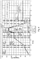
- FIG Fig. 3 The course of the temperature of the steel strip 102 over time is for the embodiment of FIG Fig. 3 in the diagram of Fig. 4 shown.
- the paths 1-12 which as explained in the illustration of Fig. 3 are shown at different times the band treatment entered.
- the atmosphere in the second chamber or the heating chamber 106 at least from entry into the second inductor 109, consists of a proportion of at least 20% hydrogen (H 2 ), preferably> 50% H 2 , and has a dew point of ⁇ -40 ° C on.
- H 2 hydrogen
- Relevant to the suppression of the selective oxidation of Si and Mn is a sufficiently short residence time of the steel strip 102 above a temperature of 700 ° C. In the embodiment according to Fig. 3 +4, this residence time should in any case be ⁇ 60 seconds, the residence time in the diagram of Fig. 4 for example, 15 seconds.
- a hot dip galvanizing line (CGL) is only rarely used with AHSS steels. Rather, there is often a need in industry to also produce conventional grades of steel strip such as thermoforming grades at competitive production costs, which conventional grades tend to be less susceptible to oxidation. In view of this, it is recommended to use a multi-purpose CGL equipped with an appendix 10 in accordance with Fig. 1 is realized.
- the chamber 1 (or the first chamber 105) may be switched off, wherein no pre-oxidation takes place in the chamber 2 (or the second chamber 107).
- the second chamber 107 in the present case the function of a Heating chamber satisfied, only the first inductor 108 and the second inductor 109 are provided, which are arranged one behind the other in the transport direction T of the steel strip 102.
- the steel strip 102 is heated at a heating rate of> 50 K / s to a holding temperature of up to 950 ° C.
- the exact holding temperature which may also be below 950 °, for example at 920 ° C, depends on the desired Austenitization. For example, the holding temperature between 840 ° C and 920 ° C, possibly also above 920 ° C.
- the first inductor 108 with longitudinal field heats the steel strip 102 to about 700 ° C
- the second inductor 109 with transverse field then the steel strip to a holding temperature of eg 920 ° C heated.
- the required holding time with which the steel strip 102 dwells at this holding temperature, is a maximum of 180 seconds, possibly also ⁇ 180 seconds, and is driven in the third chamber 112 and in the fourth chamber 115.
- the atmosphere consists of> 20% hydrogen, with a dew point of ⁇ -40 ° C. Because of the sufficiently short residence time ( ⁇ 180 seconds) and the strongly reducing atmosphere, the selective oxidation of the elements Si and Mn is suppressed, which is advantageous for very oxidation-sensitive steel grades.
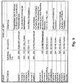
- a possible second mode of operation for a method according to the invention is described below with reference to the table of FIG Fig. 7 the resulting curve of the strip temperature over time in the diagram of Fig. 8 is shown.
- the second mode of operation also serves for the treatment or machining of AHSS steels, wherein the selective oxidation is (largely) suppressed.
- the steel strip in the first chamber 105 (“preheat chamber”) is heated to a temperature of up to 600 ° C, under an atmosphere containing exhaust gas with air shortage. Such heating is not critical for selective oxidation.
- the steel strip 102 in the second chamber 107 (or "first heating chamber”) is heated by the first inductor 108 to a maximum temperature of 700 ° C.
- the first inductor 108 can now be used in small load or with the second mode of operation run lower power, which leads to the advantage of lower energy costs compared to the first driving style.
- the remaining process steps of the second driving mode may correspond to the process steps of the first driving style, so that in order to avoid repetition of the above explanation of the Fig. 5 +6 may be referenced.
- the second driving style in the individual chambers of Appendix 10 of Fig. 1 are selected or set at this point to the entries in the table of Fig. 7 and in the diagram of Fig. 8 to get expelled.
- first and second driving modes coincide that the pre-oxidation chamber 110 is respectively out of operation.
- first heating chamber only heating by the inductors 108, 109 takes place for the steel strip 102 in the second chamber 107 ("first heating chamber").
- a possible third mode of operation for a method according to the invention is described below with reference to the table of FIG Fig. 9 the resulting curve of the strip temperature over time in the diagram of Fig. 10 is shown.
- the third method of operation is for machining AHSS steels, whereby a pre-oxidation is carried out here.
- the steel strip 102 is heated under open heating by means of the directly heated furnace part 106 to a temperature of at least 600 ° C.
- the steel strip 102 subsequently enters the second chamber 107, it is precisely heated to a temperature in the range of 650-700 ° C by the first inductor 108 to prepare for pre-oxidation.
- the steel strip 102 After being heated by the first inductor 108, the steel strip 102 passes through the pre-oxidation chamber 110 under a hydrogen-containing atmosphere. Subsequently, the steel strip 102 is heated in the second chamber 107 by the second inductor 109 to just below the austenitizing (eg, about 820 ° C) at a heating rate> 50 K / s. The range of ferrite to austenite conversion is slowly traversed in the third chamber 112 ("second heating chamber"). Depending on the mode of operation or control of the second inductor 109 and the selected heating rate through the radiant tube furnace 113 in the third chamber 112, a differently long holding time or residence time for the steel strip 102 can be set. This is advantageous for steel grades which, for reasons of microstructure, require slow austenitization and, in addition, a longer hold time. In any case, in the third chamber 112 and in the fourth chamber 115, the desired reduction for the steel strip 102 takes place.
- the austenitizing eg, about 8
- the second inductor 109 is operated at partial load, which advantageously leads to lower energy costs.
- the steel strip 102 has a temperature of 820 ° C.
- the heating rate in the third chamber 112 (“second heating chamber") is a good 2 K / s. This is at the end of the path 8 for the steel strip 102 reaches a holding temperature of 920 ° C (see. Fig. 10 ).
- the paths 9-13 are available in the third chamber 112, with a holding time of approximately 84 seconds.
- a possible fourth mode of operation for a method according to the invention also serves for AHSS steels with preset pre-oxidation, and is described below with reference to the table of FIG Fig. 11 the resulting curve of the strip temperature over time in the diagram of Fig. 12 is shown.
- the heating of the steel strip 102 in the first chamber 105, the subsequent heating in the second chamber 107 ("first heating chamber”) by the first inductor 108 and the treatment in the pre-oxidation chamber 110 are performed in the same manner as in the third mode , It should now be noted in the fourth mode of operation that the second inductor 109 remains switched off at the end of the second chamber 107.
- the steel strip 102 when entering the third chamber 112 ("second heating chamber"), the steel strip 102 only has a temperature of 700 ° C.
- the steel strip 102 in the third chamber 112 is conventionally heated by the jet tubes 114 at a lower heating rate.
- the holding temperature of 920 ° C. for the steel strip 102 in the third chamber 112 is reached only at the end of the belt path 10. For holding at the holding temperature of 920 ° C, only the paths 11-13 are available in the third chamber 112, wherein the holding time or residence time is about 47 seconds.
- Another advantageous aspect of the operation with the inductive rapid heating is that the transmitted heat flow from electrical quantities with good accuracy is known.
- heat flow and band data can be concluded that the temperature of the steel strip 102.
- a radiation pyrometer after an inductor can be evaluated with known strip temperature on the determination of the emissivity.
- the temperature of the steel strip 102 remains constant, whereby the surface and thus the emissivity can change greatly.
- This "online" specific emissivity of the steel strip 102 can be used via the thermal furnace model for precise guidance of the further heating in the radiant tube furnace.
- such a plant 10 is a multipurpose CGL, with which both a heat treatment of a steel strip with suppressed selective oxidation and a conventional treatment with pre-oxidation can be realized is, and in addition, the cost-effective production of comparatively undemanding filling grades of steel strips is possible.
Abstract
Die Erfindung betrifft ein Verfahren und eine Anlage (10) zum Schmelztauchbeschichten eines in einer Transportrichtung (T) bewegten Stahlbands (102) hochfester Güte, insbesondere von oxidationsempfindlichen AHSS-Qualitäten, umfassend ein Schmelztauchbad (104), in welches das Stahlband (102) zum Beschichten eintauchbar ist, wobei - in der Transportrichtung (T) des Stahlbandes (102) gesehen - stromaufwärts von dem Schmelztauchbad (104) zumindest eine erste Heizkammer (107) mit zumindest einem Induktor (108, 109), eine Schnellkühlkammer (116) und eine Haltekammer (117) für ein Partitioning des Stahlbandes (102) angeordnet sind.The invention relates to a method and a system (10) for hot dip coating a steel strip (102) of high strength, which is moved in a transport direction (T), in particular of oxidation-sensitive AHSS qualities, comprising a hot dip bath (104) into which the steel strip (102) is used Coating can be immersed, with at least one first heating chamber (107) with at least one inductor (108, 109), one rapid cooling chamber (116) and one - seen in the transport direction (T) of the steel strip (102) - upstream of the hot-dip bath (104) Holding chamber (117) for partitioning the steel strip (102) are arranged.
Description
Die Erfindung betrifft ein Verfahren für eine kontinuierliche Wärmebehandlung eines Stahlbands nach dem Oberbegriff von Anspruch 1 bzw. nach dem Oberbegriff von Anspruch 7, und eine Anlage zum Schmelztauchbeschichten eines Stahlbands hochfester Güte, das in einer Transportrichtung bewegt wird.The invention relates to a method for a continuous heat treatment of a steel strip according to the preamble of
Übliche hochfeste Bandstähle enthalten als Legierungselemente Mn, Si und/oder Al. Bei der rekristallisierenden Glühung vor der Schmelztauchbeschichtung diffundieren diese Legierungselemente zur Oberfläche hin. Da diese Legierungselemente sehr sauerstoff-affin sind, werden sie, soweit sie sich in geringer Tiefe im Band oder an dessen Oberfläche befinden, nahezu unvermeidlich oxidiert. Das Grundmaterial Eisen wird dabei nicht oxidiert. Man spricht deshalb von selektiver Oxidation. Die an der Oberfläche oder in geringer Tiefe gebildeten Oxide beeinträchtigen die Benetzbarkeit eines Stahlbands mit einem Überzugsmetall z.B. in schmelzflüssiger Form, mit der Folge von Fehlstellen (bare spots) bzw. einer schlechten Haftung des metallischen Überzuges.Conventional high-strength strip steels contain Mn, Si and / or Al as alloying elements. In the recrystallizing annealing prior to the hot dip coating, these alloying elements diffuse toward the surface. Since these alloying elements are very oxygen affinitive, they are almost inevitably oxidized, as far as they are at shallow depths in the band or on its surface. The basic material iron is not oxidized. This is why we speak of selective oxidation. The oxides formed on the surface or at a shallow depth affect the wettability of a steel strip with a coating metal, e.g. in molten form, with the result of imperfections (bare spots) or poor adhesion of the metallic coating.
In Anbetracht der vorstehend genannten Problematik der selektiven Oxidation ist nach dem Stand der Technik als Gegenmaßnahme die sogenannte Vor-Oxidation bekannt, bei der ein Abdecken dieser Oxide durch eine FeO- Schicht und eine nachfolgende Reduktion zu Eisen (Fe) erfolgt. Dies erzeugt an bzw. auf der Oberfläche eines zu beschichteten Stahlbands eine reine Fe- Schicht, worauf ein metallischer Überzug gut haftet. Diesbezüglich besteht bei einigen Materialen die Tendenz, dass die Haftung in größerer Tiefe versagt, da die selektiv gebildeten Oxide wie MnO u.a. eine Passivschicht erzeugen, auf der die Haftung der Rein-Fe-Schicht schlecht ist.In view of the above-mentioned problem of selective oxidation, the state of the art as a countermeasure known as the pre-oxidation, in which a coverage of these oxides by a FeO layer and a subsequent reduction to iron (Fe) takes place. This creates on or on the surface To a coated steel strip a pure Fe layer, whereupon a metallic coating adheres well. In this regard, some materials tend to fail adhesion at a greater depth because the selectively formed oxides such as MnO and others produce a passive layer on which the adhesion of the pure Fe layer is poor.
Der Erfindung liegt die Aufgabe zugrunde, zur Vorbereitung einer Beschichtung von Stahlbändern die selektive Oxidation so weit zu unterdrücken, dass diese Oxide für das anschließende Aufbringen eines metallischen Überzugs auf eine Oberfläche des Stahlbands nicht mehr stören.The object of the invention is to suppress the selective oxidation to the extent that these oxides do not interfere with the subsequent application of a metallic coating to a surface of the steel strip in order to prepare a coating of steel strips.
Diese Aufgabe wird durch ein Verfahren mit den Merkmalen von Anspruch 1 und von Anspruch 7, als auch durch eine Anlage mit den in Anspruch 15 angegebenen Merkmalen gelöst. Vorteilhafte Weiterbildung der Erfindung sind in den abhängigen Ansprüchen definiert.This object is achieved by a method having the features of
Mit einem erfindungsgemäßen Verfahren wird eine kontinuierliche Wärmebehandlung eines Stahlbands hochfester Güte, insbesondere von oxidationsempfindlichen AHSS- Qualitäten, durchgeführt, wobei das Stahlband durch zumindest eine Ofeneinrichtung bewegt wird. Ein solches Verfahren umfasst folgende Schritte:
- a) Erwärmen des Stahlbands in einer Atmosphäre, die ≥ 20 %, vorzugsweise ≥ 50 % Wasserstoff (H2) und Rest Stickstoff (N2) enthält und einen Taupunkt von < -40 °C aufweist, wobei das Stahlband spätestens ab 750 °C mit einer Heizrate von zumindest 50 K/s auf eine Haltetemperatur zwischen ≥ 800 °C und ≤ 950 °C erwärmt wird, wobei das Stahlband in dieser Atmosphäre oberhalb von 750°C mit einer Verweildauer von maximal 180 Sekunden verweilt,
- b) Schnellkühlen des Stahlbands auf < 500 °C unter einer wasserstoffhaltigen Atmosphäre, und
- c) Aufbringen eines metallischen Überzugs auf zumindest eine Oberfläche des Stahlbands.
- a) heating of the steel strip in an atmosphere containing ≥ 20%, preferably ≥ 50% hydrogen (H 2 ) and the balance nitrogen (N 2 ) and having a dew point of <-40 ° C, wherein the steel strip latest from 750 ° C. at a heating rate of at least 50 K / s a holding temperature between ≥ 800 ° C and ≤ 950 ° C is heated, the steel strip dwells in this atmosphere above 750 ° C with a residence time of a maximum of 180 seconds,
- b) rapid cooling of the steel strip to <500 ° C under a hydrogen-containing atmosphere, and
- c) applying a metallic coating to at least one surface of the steel strip.
Ein erfindungsgemäßes Verfahren nach einer weiteren Ausführungsform dient ebenfalls für eine kontinuierliche Wärmebehandlung eines Stahlbands hochfester Güte, insbesondere von oxidationsempfindlichen AHSS- Qualitäten, bei dem das Stahlband durch zumindest eine Ofeneinrichtung bewegt wird. Hierbei umfasst das Verfahren folgende Schritte:
- i) Erwärmen des Stahlbands (102) auf eine Temperatur von mindestens
600 °C durch einen direkt beheizten Vorwärmer (DFF = Direct Fired Furnace) (106) in einer Abgas-Atmosphäre mit Luftmangel, - ii) Erwärmen des Stahlbands (102) auf eine Temperatur zwischen 700 °C - 750 °C durch einen Induktor in einer wasserstoffhaltigen Atmosphäre,
- iii) Wärmebehandlung des Stahlbands in einer oxidierenden Atmosphäre mit einem Sauerstoffgehalt von 2-5 % O2, um dadurch an den Oberflächen des Stahlbandes Eisenoxidschichten auszubilden, wobei diese Wärmebehandlung eine Zeitdauer von 5-20 Sekunden hat,
- iv) Erwärmen des Stahlbands auf eine Temperatur von bis zu 950 °C in einer Atmosphäre, die Wasserstoff (H2), Wasserdampf und Rest Stickstoff (N2) enthält, wobei das Stahlband bei einer Temperatur von bis zu 950 °C mit einer Zeitdauer von ≥ 40 Sekunden gehalten wird,
- v) Schnellkühlen des Stahlbands auf < 500 °C unter einer wasserstoffhaltigen Atmosphäre, und
- vi) Aufbringen eines metallischen Überzugs auf zumindest eine Oberfläche des Stahlbands.
- i) heating the steel strip (102) to a temperature of at least
600 ° C by a directly heated pre-heater (DFF = Direct Fired Furnace) (106) in an exhaust atmosphere with lack of air, - ii) heating the steel strip (102) to a temperature between 700 ° C - 750 ° C by an inductor in a hydrogen-containing atmosphere,
- iii) heat treating the steel strip in an oxidizing atmosphere having an oxygen content of 2-5% O 2 to thereby form iron oxide layers on the surfaces of the steel strip, this heat treatment having a duration of 5-20 seconds,
- iv) heating the steel strip to a temperature of up to 950 ° C in an atmosphere containing hydrogen (H 2 ), water vapor and balance nitrogen (N 2 ), the steel strip at a temperature of up to 950 ° C with a period of time of ≥ 40 seconds,
- v) rapid cooling of the steel strip to <500 ° C under a hydrogen-containing atmosphere, and
- vi) applying a metallic coating to at least one surface of the steel strip.
Bei beiden der vorstehend genannten Varianten eines erfindungsgemäßen Verfahrens kann für den Schritt c) bzw. vi) eine Beschichtungseinrichtung vorgesehen sein, die - in der Transportrichtung des Stahlbandes gesehen - stromabwärts von einer Ofeneinrichtung angeordnet ist. Eine solche Beschichtungseinrichtung kann als Schmelztauchbad oder in Form einer PVD (= Physical Vapor Deposition)-Sektion ausgebildet sein, um auf zumindest eine Oberfläche der Stahlbandes, vorzugsweise auf den Oberflächen des Stahlbandes an dessen Ober- und Unterseite, einen metallischen Überzug aufzubringen. Bei Ausgestaltung der Beschichtungseinrichtung als Schmelztauchbad ist es zweckmäßig, wenn darin das Stahlband insbesondere mit Zink tauchbeschichtet wird.In both of the abovementioned variants of a method according to the invention, a coating device can be provided for step c) or vi) which, viewed in the transport direction of the steel strip, is arranged downstream of a furnace device. Such a coating means may be formed as a hot dipping bath or in the form of a PVD (= P hysical V apor D eposition) section to apply to at least one surface of the steel strip, preferably on the surfaces of the steel strip at the top and bottom surfaces, a metal coating , When designing the coating device as a hot dip, it is useful if the steel strip is dip-coated in particular with zinc.
In vorteilhafter Weiterbildung des zweitgenannten erfindungsgemäßen Verfahrens kann vorgesehen sein, dass in Schritt iv) das Stahlband durch einen RTF-Ofenteil (RTF = Radiant Tube Furnace) erwärmt wird, vorzugsweise, dass das Stahlband zu Beginn des Schritts iv) zusätzlich durch einen Querfeld-Induktor mit einer Heizrate von zumindest 50 K/s auf zumindest 820 °C erwärmt wird. Die Erwärmung des Stahlbandes mittels des Querfeld-Induktors zu Beginn des Schritts iv) führt zu dem Vorteil, dass wegen der genannten hohen Heizrate das Stahlband schneller auf die gewünschte Haltetemperatur gebracht wird.In an advantageous embodiment of the second-mentioned method according to the invention can be provided that in step iv) the steel strip is heated by a RTF furnace section (RTF = Radiant Tube Furnace), preferably, that the steel strip at the beginning of step iv) additionally by a transverse field inductor is heated to at least 820 ° C at a heating rate of at least 50 K / s. The heating of the steel strip by means of the transverse field inductor at the beginning of step iv) leads to the advantage that because of the said high heating rate, the steel strip is brought to the desired holding temperature more quickly.
Die Erfindung sieht ebenfalls eine Anlage zum Schmelztauchbeschichten eines in einer Transportrichtung bewegten Stahlbands hochfester Güte, insbesondere von oxidationsempfindlichen AHSS-Qualitäten, vor. Eine solche Anlage umfasst ein Schmelztauchbad, in welches das Stahlband zum Beschichten eingetaucht werden kann, wobei - in der Transportrichtung des Stahlbandes gesehen - stromaufwärts von dem Schmelztauchbad zumindest eine erste Heizkammer mit zumindest einem Induktor, vorzugsweise in Form eines Querfeld-Induktors, eine Schnellkühlkammer und eine Haltekammer für ein Partitioning des Stahlbandes angeordnet sind. Zweckmäßigerweise können im Einlaufbereich der Haltekammer bzw. stromaufwärts hiervon ein Induktor und/oder im Auslaufbereich der Haltekammer ein weiterer Induktor vorgesehen sein.The invention likewise provides a system for hot-dip coating of a steel strip of high-strength quality moving in a transport direction, in particular of oxidation-sensitive AHSS grades. Such a plant comprises a hot dip bath into which the steel strip is immersed for coating can be, wherein - seen in the transport direction of the steel strip - upstream of the Schmelztauchbad at least a first heating chamber with at least one inductor, preferably in the form of a transverse field inductor, a rapid cooling chamber and a holding chamber for a partitioning of the steel strip are arranged. Conveniently, an inductor and / or in the outlet region of the holding chamber, a further inductor may be provided in the inlet region of the holding chamber or upstream thereof.
Der Erfindung liegt die wesentliche Erkenntnis zugrunde, dass die Bandaufheizung bzw. das Erwärmen des Stahlbands auf eine Temperatur von bis zu 950 °C möglichst schnell erfolgt, wobei die anschließende Halte- bzw. Verweilzeit für das Stahlband auf einer vorbestimmten Temperatur klein zu sein hat. Dies führt zu dem Vorteil, dass während des Aufheizens eine selektive Oxidation (weitgehend) unterdrückt werden kann. Zu diesem Zweck ist es grundsätzlich von Vorteil, die Atmosphäre, in der das Stahlband erwärmt wird, so reduzierend wie möglich einzustellen, nämlich mit möglichst großem bzw. maximalem Wasserstoff-Gehalt und minimalem Taupunkt, wobei gleichzeitig eine Heizrate von > 50 K/s eingestellt wird. Dies gilt bei dem erstgenannten erfindungsgemäßen Verfahren für den Schritt a), und bei dem zweitgenannten erfindungsgemäßen Verfahren für den Schritt iv).The invention is based on the essential finding that the strip heating or the heating of the steel strip to a temperature of up to 950 ° C takes place as quickly as possible, the subsequent holding or dwell time for the steel strip has to be small at a predetermined temperature. This leads to the advantage that during the heating a selective oxidation can be (largely) suppressed. For this purpose, it is fundamentally advantageous to set the atmosphere in which the steel strip is heated as reducing as possible, namely with the largest possible or maximum hydrogen content and a minimum dew point, with a heating rate of> 50 K / s being set at the same time becomes. This applies in the first-mentioned method according to the invention for step a), and in the second-mentioned method according to the invention for step iv).
In vorteilhafter Weiterbildung der Erfindung kann vorgesehen sein, dass die Temperatur, auf welche das Stahlband im Schritt a) bzw. im Schritt iv) erwärmt und vorzugsweise auch gehalten wird, unterhalb von 950 °C liegt und z.B. einen Wert von 945 °C, 940 °C, 935 °C, 930 °C, 925 °C oder 920 °C annimmt. Diesbezüglich ist es auch möglich, dass diese Temperatur, auf welche das Stahlband im Schritt a) bzw. im Schritt iv) erwärmt und vorzugsweise auch gehalten wird, einen Wert annimmt, der zwischen den soeben genannten Beispielwerten liegt, und z.B. einen Wert von 942 °C oder andere Zwischenwerte annimmt.In an advantageous embodiment of the invention can be provided that the temperature to which the steel strip in step a) or in step iv) is heated and preferably maintained below 950 ° C and, for example, a value of 945 ° C, 940 ° C, 935 ° C, 930 ° C, 925 ° C or 920 ° C. In this regard, it is also possible that this temperature, to which the steel strip is heated and preferably also held in step a) or in step iv), assumes a value which lies between the example values just mentioned, and for example a value of 942 ° C or other intermediate values.
Um die Oxidation an den Oberflächen des Stahlbandes oberhalb von Temperaturen von etwa 700 °C wirksam zu unterdrücken, muss die Verweilzeit des Stahlbands > 750 °C so kurz wie möglich sein. Zur Realisierung dessen hat sich erfindungsgemäß für das Erwärmen des Stahlbands auf eine Temperatur von bis zu 950 °C gezeigt, dass mit einer Atmosphäre mit zumindest einem Anteil von 20 % Wasserstoff, vorzugsweise Rest Stickstoff, und einem Taupunkt von weniger bzw. kleiner als -40 °C Verweilzeiten für das Stahlband bis maximal 180 Sekunden zulässig sind. Je nach Beschaffenheit des zu beschichtendes Stahlbands kann diese Verweilzeiten auch kürzer als 180 Sekunden sein. Jedenfalls wird während der Halte- bzw. Verweilzeit das Material des Stahlbands teilweise oder vollständig in Austenit umgewandelt.In order to effectively suppress the oxidation at the surfaces of the steel strip above temperatures of about 700 ° C, the residence time of the steel strip> 750 ° C must be as short as possible. To realize this, according to the invention for the heating of the steel strip to a temperature of up to 950 ° C has shown that with an atmosphere having at least a proportion of 20% hydrogen, preferably nitrogen, and a dew point of less than or less than -40 ° C residence times for the steel strip are allowed up to a maximum of 180 seconds. Depending on the nature of the steel strip to be coated, these residence times may also be shorter than 180 seconds. In any case, the material of the steel strip is partially or completely converted into austenite during the holding or residence time.
Bei beiden der genannten Ausführungsformen eines erfindungsgemäßen Verfahrens ist vorgesehen, dass für das Stahlband ein Schnellkühlen unter einer wasserstoffhaltigen Atmosphäre auf < 500 °C durchgeführt wird, wie es im Schritt a) bzw. im Schritt v) definiert ist. Für ein solches Schnellkühlen kann die Kühlrate zumindest 40 K/s betragen, wofür ein hoher Wasserstoffgehalt zweckmäßig ist. Vorteilhafterweise wird ein wasserstoffreiches Schutzgas mit einem Anteil von z.B. 50% Wasserstoff im Aufheizteil und/oder in der Langsamkühlung zur Vermeidung der Oxidation eingesetzt.In both of the aforementioned embodiments of a method according to the invention, it is provided that rapid cooling is carried out for the steel strip under a hydrogen-containing atmosphere at <500 ° C., as defined in step a) or in step v). For such rapid cooling, the cooling rate can be at least 40 K / s, for which a high hydrogen content is expedient. Advantageously, a hydrogen-rich inert gas with a proportion of e.g. 50% hydrogen used in the heating part and / or in the slow cooling to avoid oxidation.
In vorteilhafter Weiterbildung des erstgenannten erfindungsgemäßen Verfahrens kann vorgesehen sein, dass das Stahlband vor dem Schritt a) durch einen direkt beheizten Vorwärmer (DFF = Direct Fired Furnace) in einer Abgas-Atmosphäre mit Luftmangel auf eine Temperatur von bis zu 750 °C erwärmt wird. Bei einem solchen Aufwärmen ist die Oxidationsneigung für das Stahlband in der Regel noch unkritisch, wobei für bestimmte Güten Aufheizraten von 15-20 K/s ausreichend sind. Des Weiteren wird mit einem solchen Erwärmen des Stahlbands hierfür vorteilhaft ein höheres Temperaturniveau erreicht, zur Vorbereitung der anschließenden intensiven Erwärmung im Schritt a).In an advantageous embodiment of the first-mentioned method according to the invention can be provided that the steel strip is heated to a temperature of up to 750 ° C by a directly heated preheater (DFF = Direct Fired Furnace) in an exhaust atmosphere with lack of air before step a). In such a warming, the tendency to oxidation of the steel strip is usually not critical, with heating rates of 15-20 K / s are sufficient for certain grades. Furthermore, with such heating of the steel strip therefor advantageously reaches a higher temperature level, in preparation for the subsequent intensive heating in step a).
In vorteilhafter Weiterbildung des erstgenannten erfindungsgemäßen Verfahrens kann vorgesehen sein, dass in Schritt a) das Stahlband durch zumindest einen Induktor, vorzugsweise in Form eines Querfeld-Induktors, auf die Haltetemperatur von bis zu 950 °C erwärmt wird. Hierdurch ist es möglich, ein schnelles Aufheizen für das Stahlband mit einer Heizrate von zumindest 50 K/s zu erzielen.In an advantageous embodiment of the first-mentioned method according to the invention can be provided that in step a) the steel strip is heated by at least one inductor, preferably in the form of a transverse field inductor, to the holding temperature of up to 950 ° C. This makes it possible to achieve a rapid heating for the steel strip with a heating rate of at least 50 K / s.
In vorteilhafter Weiterbildung des erstgenannten erfindungsgemäßen Verfahrens kann vorgesehen sein, dass in Schritt a) das Stahlband induktiv in zwei Stufen erwärmt wird, wobei das Stahlband durch einen ersten Induktor, vorzugsweise in Form eines Längsfeld-Induktors, zunächst auf eine Temperatur von bis zu 720 °C erwärmt wird und anschließend durch einen zweiten Induktor, vorzugsweise in Form eines Querfeld-Induktors, auf die Haltetemperatur von bis zu 950 °C erwärmt wird.In an advantageous embodiment of the first-mentioned method according to the invention can be provided that in step a) the steel strip is inductively heated in two stages, the steel strip by a first inductor, preferably in the form of a longitudinal field inductor, initially to a temperature of up to 720 ° C is heated and then heated by a second inductor, preferably in the form of a transverse field inductor, to the holding temperature of up to 950 ° C.
Wie vorstehend bereits erläutert, kann die Verweildauer bei dem erstgenannten erfindungsgemäßen Verfahren in Schritt a) auch weniger als 180 Sekunden betragen. Diesbezüglich wird darauf hingewiesen, dass diese Verweildauer im Rahmen der vorliegende Erfindung auch ≤ 170 Sekunden, vorzugsweise ≤ 160 Sekunden, weiter vorzugsweise ≤ 150 Sekunden, weiter vorzugsweise ≤ 140 Sekunden, weiter vorzugsweise ≤ 130 Sekunden, weiter vorzugsweise ≤ 120 Sekunden, weiter vorzugsweise ≤ 110 Sekunden, weiter vorzugsweise ≤ 100 Sekunden, weiter vorzugsweise ≤ 90 Sekunden, weiter vorzugsweise ≤ 85 Sekunden, weiter vorzugsweise ≤ 80 Sekunden, weiter vorzugsweise ≤ 75 Sekunden, weiter vorzugsweise ≤ 70 Sekunden, weiter vorzugsweise ≤ 65 Sekunden, weiter vorzugsweise ≤ 60 Sekunden, weiter vorzugsweise ≤ 55 Sekunden, weiter vorzugsweise ≤ 50 Sekunden, weiter vorzugsweise ≤ 45 Sekunden, weiter vorzugsweise ≤ 40 Sekunden, weiter vorzugsweise ≤ 35 Sekunden, weiter vorzugsweise ≤ 30 Sekunden, weiter vorzugsweise ≤ 25 Sekunden, weiter vorzugsweise ≤ 20 Sekunden, weiter vorzugsweise ≤ 15 Sekunden, weiter vorzugsweise ≤ 10 Sekunden, weiter vorzugsweise ≤ 5 Sekunden betragen kann, je nach Materialbeschaffenheit des zu beschichtenden Stahlbandes.As already explained above, the residence time in the first-mentioned process according to the invention in step a) can also be less than 180 seconds. In this regard, it should be noted that this residence time in the context of the present invention also ≤ 170 seconds, preferably ≤ 160 seconds, more preferably ≤ 150 seconds, more preferably ≤ 140 seconds, more preferably ≤ 130 seconds, more preferably ≤ 120 seconds, more preferably ≤ 110 seconds, more preferably ≤100 seconds, more preferably ≤90 seconds, more preferably ≤85 seconds, more preferably ≤80 seconds, more preferably ≤75 seconds, more preferably ≤70 seconds, further preferably ≤65 seconds, further preferably ≤60 seconds , more preferably ≦ 55 seconds, more preferably ≦ 50 seconds, more preferably ≦ 45 seconds, further preferably ≦ 40 seconds, further preferably ≦ 35 Seconds, more preferably ≤30 seconds, more preferably ≤25 seconds, more preferably ≤20 seconds, more preferably ≤15 seconds, more preferably ≤10 seconds, more preferably ≤5 seconds, depending on the material condition of the steel strip to be coated.
In vorteilhafter Weiterbildung der Erfindung kann vorgesehen sein, dass das Stahlband bei dem Schnellkühlen in Schritt b) bzw. in Schritt v) auf eine Temperatur gekühlt wird, die in einem Bereich zwischen 200 °C und 450 °C liegt. Für diesen Fall ist es weiter zweckmäßig, dass dann vor dem Schritt c) bzw. im Anschluss an Schritt v) ein Erwärmen des Stahlbands auf eine Partitioning-Temperatur von zumindest 300 °C, vorzugsweise 320 °C, in einer Atmosphäre, die ≥ 20 % Wasserstoff (H2) und Rest Stickstoff (N2) enthält, durchgeführt wird, wobei das Stahlband in dieser Atmosphäre für eine Dauer von ≥ 30 Sekunden verweilt.In an advantageous embodiment of the invention can be provided that the steel strip is cooled in the rapid cooling in step b) or in step v) to a temperature which is in a range between 200 ° C and 450 ° C. In this case, it is further expedient for the steel strip to be heated to a partitioning temperature of at least 300 ° C., preferably 320 ° C., in an atmosphere which is ≥ 20 before step c) or following step v) % Hydrogen (H 2 ) and balance nitrogen (N 2 ) is carried out with the steel strip in this atmosphere for a period of ≥ 30 seconds dwell.
In vorteilhafter Weiterbildung der Erfindung kann vorgesehen sein, dass für das Stahlband ein Langsamkühlen durchgeführt wird. Bei dem erstgenannten erfindungsgemäßen Verfahren erfolgt ein solches Langsamkühlen zwischen den Schritten a) und b), wobei bei dem zweitgenannten erfindungsgemäßen Verfahren ein solches Langsamkühlen zwischen den Schritten iv) und v) erfolgt. Jedenfalls ist es von Vorteil, wenn ein solches Langsamkühlen unter einer wasserstoffhaltigen Atmosphäre erfolgt, die z.B. einen Anteil von zumindest 20 % Wasserstoff enthalten und einen Taupunkt von < -40 °C aufweisen kann. Des Weiteren ist von Vorteil, wenn diese Atmosphäre neben dem Wasserstoffanteil dann Rest Stickstoff enthält. Jedenfalls ist für das Langsamkühlen von Bedeutung bzw. von Vorteil, dass dabei das Mischphasengebiet Ferrit + Austenit mit langsamer Abkühlung durchfahren wird, je nach Legierung bis herunter auf 750 °C, um dadurch einen definierten Austenit-Anteil einzustellen. Deswegen ist die Zeit der Langsamkühlung hinsichtlich die Oxidation von Si Teil der vorstehend genannten Verweilzeit.In an advantageous embodiment of the invention can be provided that a slow cooling is performed for the steel strip. In the first-mentioned method according to the invention, such slow cooling takes place between steps a) and b), whereby in the case of the second-mentioned method according to the invention, such slow cooling takes place between steps iv) and v). In any case, it is advantageous if such slow cooling takes place under a hydrogen-containing atmosphere which, for example, contains at least 20% hydrogen and may have a dew point of <-40 ° C. Furthermore, it is advantageous if this atmosphere in addition to the hydrogen content then contains residual nitrogen. In any case, it is important or advantageous for slow cooling that the mixed phase region ferrite + austenite is passed through with slow cooling, depending on the alloy down to 750 ° C., in order to thereby set a defined austenite content. Therefore, the time of slow cooling with respect to the oxidation of Si is part of the above-mentioned residence time.
In vorteilhafter Weiterbildung der Erfindung können für die kontinuierliche Wärmebehandlung des Stahlbandes weitere Prozessschritte vorgesehen sein, bei denen es sich z.B. um ein Wiederaufheizen und/oder um ein Halten des Stahlbands handeln kann. Diese möglichen weiteren Prozessschritte werden bei Temperaturen >> 600 °C gefahren und sind daher hinsichtlich der Oxidation von Si unerheblich. Ein hoher Wasserstoffgehalt ist hierbei zwar nicht erforderlich, jedoch auch nicht von Nachteil, so dass für diese weiteren Prozessschritte grundsätzlich in der gleichen Atmosphäre wie die vorhergehende Schnellkühlung gefahren werden kann.In an advantageous embodiment of the invention, further process steps may be provided for the continuous heat treatment of the steel strip, which may be e.g. may be a reheating and / or a holding of the steel strip. These possible further process steps are driven at temperatures of> 600 ° C and are therefore irrelevant with regard to the oxidation of Si. Although a high hydrogen content is not required in this case, it is not disadvantageous, so that it is basically possible to drive for these further process steps in the same atmosphere as the preceding rapid cooling.
Nachstehend sind bevorzugte Ausführungsformen der Erfindung anhand einer schematisch vereinfachten Zeichnung im Detail beschrieben. Es zeigen:
- Fig. 1
- eine prinzipielle Seitenansicht einer erfindungsgemäßen Anlage,
- Fig. 2
- eine prinzipielle Seitenansicht einer erfindungsgemäßen Anlage nach einer weiteren Ausführungsform,
- Fig. 3
- eine prinzipielle Seitenansicht einer erfindungsgemäßen Anlage nach einer weiteren Ausführungsform,
- Fig. 4
- den Temperaturverlauf für ein Stahlband bei einer Behandlung in der Anlage von
Fig. 3 , - Fig. 5
- eine tabellarische Übersicht zu Parametern einer möglichen Fahrweise eines erfindungsgemäßen Verfahrens,
- Fig. 6
- den Temperaturverlauf für ein Stahlband bei der Fahrweise von
Fig. 5 , - Fig. 7
- eine tabellarische Übersicht zu Parametern einer möglichen Fahrweise eines erfindungsgemäßen Verfahrens gemäß einer weiteren Ausführungsform,
- Fig. 8
- den Temperaturverlauf für ein Stahlband bei der Fahrweise von
Fig. 7 , - Fig. 9
- eine tabellarische Übersicht zu Parametern einer möglichen Fahrweise eines erfindungsgemäßen Verfahrens gemäß einer weiteren Ausführungsform,
- Fig. 10
- den Temperaturverlauf für ein Stahlband bei der Fahrweise von
Fig. 9 , - Fig. 11
- eine tabellarische Übersicht zu Parametern einer möglichen Fahrweise eines erfindungsgemäßen Verfahrens gemäß einer weiteren Ausführungsform, und
- Fig. 12
- den Temperaturverlauf für ein Stahlband bei der Fahrweise von
Fig. 11 .
- Fig. 1
- a schematic side view of a system according to the invention,
- Fig. 2
- a schematic side view of a system according to the invention according to a further embodiment,
- Fig. 3
- a schematic side view of a system according to the invention according to a further embodiment,
- Fig. 4
- the temperature curve for a steel strip during a treatment in the plant of
Fig. 3 . - Fig. 5
- a tabular overview of parameters of a possible driving style of a method according to the invention,
- Fig. 6
- the temperature curve for a steel strip in the driving style of
Fig. 5 . - Fig. 7
- a tabular overview of parameters of a possible driving style of a method according to the invention according to a further embodiment,
- Fig. 8
- the temperature curve for a steel strip in the driving style of
Fig. 7 . - Fig. 9
- a tabular overview of parameters of a possible driving style of a method according to the invention according to a further embodiment,
- Fig. 10
- the temperature curve for a steel strip in the driving style of
Fig. 9 . - Fig. 11
- a tabular overview of parameters of a possible driving style of a method according to the invention according to another embodiment, and
- Fig. 12
- the temperature curve for a steel strip in the driving style of
Fig. 11 ,
Nachstehend sind unter Bezugnahme auf die
Zur Wärmebehandlung des Stahlbands 102 umfasst die Anlage 10 mehrere Kammern, durch die das Stahlband 102 nacheinander für ein Aufheizen bzw. ein Abkühlen hindurch geführt wird, bevor es zum Aufbringen der Zinkschicht in das Schmelztauchbad 104 eingebracht wird. Die einzelnen Kammern der Anlage 10 sind folgende:
- Kammer 1: Vorheizkammer, direkt befeuert; in
Fig. 1 mit "105" bezeichnet; - Kammer 2: erste Heizkammer zur Schnellaufheizung, optional mit einer Vor-Oxidation ausgestattet; in
Fig. 1 mit "107" bezeichnet; - Kammer 3: zweite Heizkammer, strahlrohrbeheizt, dient zum Langsam-Aufheizen und zum Halten; in
Fig. 1 mit "112" bezeichnet; - Kammer 4: Langsamkühlkammer; in
Fig. 1 mit "115" bezeichnet; - Kammer 5: Schnellkühlkammer; in
Fig. 1 mit "116" bezeichnet; - Kammer 6: Kammer für ein Partitioning bzw. Überaltern; in
Fig. 1 mit "117" bezeichnet.
- Chamber 1: preheat chamber, directly fired; in
Fig. 1 denoted by "105"; - Chamber 2: first heating chamber for rapid heating, optionally equipped with pre-oxidation; in
Fig. 1 denoted by "107"; - Chamber 3: second heating chamber, jet tube heated, used for slow heating and holding; in
Fig. 1 denoted by "112"; - Chamber 4: slow cooling chamber; in
Fig. 1 denoted by "115"; - Chamber 5: rapid cooling chamber; in
Fig. 1 denoted by "116"; - Chamber 6: Partitioning or Overaging Chamber; in
Fig. 1 denoted by "117".
Die Kammern 1-6 werden diesen Ziffern entsprechend nachfolgend auch als erste bis sechse Kammer bezeichnet.The chambers 1-6 are referred to hereinafter as the first to six-sixth chamber according to these numbers.
Die prinzipiell vereinfachte Seitenansicht gemäß
Die einzelnen Kammern gemäß der Ausführungsform von
- Die erste Kammer bzw.
Vorheizkammer 105 ist mit zumindest einem direkt beheizten Vorwärmer bzw. Ofenteil (DFF = Direct Fired Furnace) ausgestattet, mitdem das Stahlband 102 auf eine Temperatur von zumindest 600 °C erwärmt werden kann. Insoweit erfüllt dieerste Kammer 105 die Funktion einer Vorheizkammer.Die erste Kammer 105 umfasst dieBandpfade 1+2. die ersteKammer 105 dient insbesondere zum kostengünstigen Aufheizen von weniger oxidationsempfindlichen Produkten bzw.Stahlbändern 102. Die zweite Kammer 107 bildet eine erste Heizkammer zur Schnellaufheizung desStahlbands 102, und ist zu diesem Zweck mit einem ersten Induktor 108 (inFig. 1 auch mit "Induktor 1" bezeichnet) und mit einem zweiten Induktor 109 (inFig. 1 auch mit "Induktor 2" bezeichnet) ausgestattet. In der Transportrichtung T desStahlbands 102 gesehen ist der zweiteInduktor 109 stromabwärts vonden ersten Induktor 108 angeordnet.Der erste Induktor 108 ist als Längsfeld- Induktor ausgebildet.Der zweite Induktor 109 ist als Querfeld-Induktor ausgebildet.Die zweite Kammer 107 umfasst dieBandpfade und 5.- Optional kann die
zweite Kammer 107 mit einerVoroxidationskammer 110 ausgestattet sein, die zwischen den erstenInduktor 108 unddem zweiten Induktor 109 angeordnet ist. Für diesen Falldurchläuft das Stahlband 102, nachdem es durchden ersten Induktor 108 erwärmt worden ist, zunächst dieVoroxidationskammer 110, bevor es dann vondem zweiten Induktor 109 erwärmt wird. Die dritte Kammer 112 bildet eine zweite Heizkammer und ist strahlrohrbeheizt, und dient zum Langsam-Aufheizen des Stahlbands 102 auf eine bestimmte Temperatur und zum anschließenden Halten auf dieser Temperatur.Die dritte Kammer 112 bildet einen RTF-Ofenteil (RTF = Radiant Tube Furnace) 113 und ist mit einerMehrzahl von Strahrohren 114 ausgestattet, die entlang der Bandpfade 6-13 angeordnet sind. Bei Bedarf lassen sich fürdas Stahlband 102 innerhalb der drittenKammer 112 auch längere Haltezeiten einstellen. Am Ende der drittenKammer 112 kann ein weiterer Induktor, z.B. in Form eines Querfeld-Induktors, vorgesehen sein, inFig. 1 mit "Induktor 3" bezeichnet.Mit dem Induktor 3kann das Stahlband 102 z.B. mit Heizraten von zumindest 50 K/s auf eine Temperatur von zumindest 820 °C erwärmt werden, bevor es diedritte Kammer 112 verlässt.Die dritte Kammer 112 umfasst die Bandpfade 6-13.Die vierte Kammer 115 dient zum Langsamkühlen desStahlbands 102, und umfasst hierzu die Bandpfade 14 + 15.Die fünfte Kammer 116 dient als Schnellkühlkammer, und ist zu diesem Zweck mit Kühleinrichtungen in Form einer "Schnellkühlung 1" und einer "Schnellkühlung 2" ausgestattet, die entlang des Bandpfades 16 nach- bzw. hintereinander angeordnet sind.Die sechste Kammer 117 dient dazu,das Stahlband 102 auf eine Partitioning-Temperatur von zumindest 300 °C, vorzugsweisevon 320 °C zu erwärmen. Im Einlaufbereich der sechstenKammer 117kann ein Induktor 4 vorgesehen sein, wobei im Auslaufbereich bzw. am Ende der sechstenKammer 117ein Induktor 5 vorgesehen sein kann.Mit diesen Induktoren kann das Stahlband 102 mit einer hohen Heizrate auf eine vorbestimmte Temperatur gebracht werden.Die sechste Kammer 117 umfasst die Bandpfade 17-24.
- The first chamber or
preheat chamber 105 is provided with at least one directly heated preheater or furnace part (DFF = Direct Fired Furnace). equipped, with which thesteel strip 102 can be heated to a temperature of at least 600 ° C. In that regard, thefirst chamber 105 performs the function of a preheat chamber. Thefirst chamber 105 comprises thetape paths 1 + 2. thefirst chamber 105 serves, in particular, for cost-effective heating of less oxidation-sensitive products or steel strips 102. - The
second chamber 107 forms a first heating chamber for rapid heating of thesteel strip 102, and for this purpose is provided with a first inductor 108 (in FIGFig. 1 also referred to as "inductor 1") and with a second inductor 109 (in FIGFig. 1 also referred to as "inductor 2"). As seen in the transport direction T of thesteel strip 102, thesecond inductor 109 is disposed downstream of thefirst inductor 108. Thefirst inductor 108 is designed as a longitudinal field inductor. Thesecond inductor 109 is designed as a transverse field inductor. Thesecond chamber 107 includes thetape paths - Optionally, the
second chamber 107 may be equipped with apre-oxidation chamber 110 disposed between thefirst inductor 108 and thesecond inductor 109. In this case, after being heated by thefirst inductor 108, thesteel strip 102 first passes through thepre-oxidation chamber 110 before being heated by thesecond inductor 109. - The
third chamber 112 forms a second heating chamber and is radiant tube heated and serves to slowly heat thesteel strip 102 to a predetermined temperature and then hold it at that temperature. Thethird chamber 112 forms a RTF (RTF = Radiant Tube Furnace)section 113 and is provided with a plurality oftubes 114 arranged along the tape paths 6-13. If necessary can be set for thesteel strip 102 within thethird chamber 112 and longer holding times. At the end of thethird chamber 112, a further inductor, for example in the form of a transverse field inductor, may be provided, in FIGFig. 1 denoted by "inductor 3". With theinductor 3, thesteel strip 102 can be heated to a temperature of at least 820 ° C, for example at heating rates of at least 50 K / s, before it leaves thethird chamber 112. Thethird chamber 112 includes the tape paths 6-13. - The
fourth chamber 115 serves for slow cooling of thesteel strip 102, and for this purpose comprises the strip paths 14 + 15. - The
fifth chamber 116 serves as a rapid cooling chamber, and is equipped for this purpose with cooling means in the form of a "rapid cooling 1" and a "rapid cooling 2", which are arranged along thebelt path 16 after or behind each other. - The
sixth chamber 117 serves to heat thesteel strip 102 to a partitioning temperature of at least 300 ° C, preferably 320 ° C. In the inlet region of thesixth chamber 117, aninductor 4 may be provided, wherein in the outlet region or at the end of thesixth chamber 117, aninductor 5 may be provided. With theseinductors steel strip 102 can be brought to a predetermined temperature with a high heating rate. Thesixth chamber 117 includes the band paths 17-24.
In den jeweiligen Kammern der Anlage 10, in denen eine Wärmebehandlung (Aufheizen oder Abkühlen) für das Stahlband 102 durchgeführt wird, sind bestimmte Atmosphären vorgesehen, denen das Stahlband 102 beim Durchlaufen der einzelnen Kammern ausgesetzt ist. Diesbezüglich wird darauf hingewiesen, dass die Öffnungen bzw. Durchlässe zwischen den einzelnen Kammern mit Dichtungen ausgestattet sind, so dass in jeder der Kammern die dafür vorgesehene Atmosphäre erhalten bleibt. Zu den Atmosphären in den einzelnen Kammern folgende Erläuterungen:
- In der ersten
Kammer 105 ist eine schwach reduzierende Atmosphäre vorgesehen, die Abgas mit (leichtem) Luftmangel enthält. - Die Atmosphäre in der zweiten Kammer 107 ("Heizkammer") besteht aus einem Anteil von zumindest 20 % Wasserstoff (H2), vorzugsweise einem Anteil von > 50 % H2, und weist einen Taupunkt von < -40 °C auf. Der restliche Anteil dieser Atmosphäre besteht aus Stickstoff (N2).
- In der vierten
Kammer 115 ist für das Langsamkühlen des Stahlbands eine Atmosphäre vorgesehen, die zumindest 20 % Wasserstoff (H2), und Rest Stickstoff (N2) enthält und dabei einen Taupunkt von < -40 °C aufweist. - In
der fünften Kammer 116, welche die Funktion einer Schnellkühlkammer erfüllt, liegt die gleiche Atmosphäre wie in der zweitenKammer 107 vor. Zugunsten einer gesteigerten Kühlleistung bzw. Kühlperformance liegt der Wasserstoff-Anteil vorzugsweise > 50%.
- In the
first chamber 105, a weak reducing atmosphere is provided containing exhaust gas with (slight) air shortage. - The atmosphere in the second chamber 107 ("heating chamber") consists of a proportion of at least 20% hydrogen (H 2 ), preferably a proportion of> 50% H 2 , and has a dew point of <-40 ° C. The remainder of this atmosphere is nitrogen (N 2 ).
- In the
fourth chamber 115, an atmosphere is provided for the slow cooling of the steel strip, which contains at least 20% hydrogen (H2), and the balance nitrogen (N2) and thereby has a dew point of <-40 ° C. - In the
fifth chamber 116, which performs the function of a rapid cooling chamber, the same atmosphere as in thesecond chamber 107 is present. In favor of an increased cooling capacity or cooling performance, the hydrogen content is preferably> 50%.
Die Darstellung von
In den einzelnen Kammern 1-6 der Anlage 10 erfolgt die Wärmebehandlung des Stahlbands 102 mit jeweils unterschiedlichen Heizraten bzw. Kühlraten. Dies wird nachfolgend anhand von verschiedenen Ausführungsformen der Erfindung im Einzelnen erläutert:
Die Ausführungsform von
The embodiment of
Bei der Ausführungsform von
Bei der Ausführungsform von
In der fünften Kammer bzw. der Schnellkühlkammer 116 liegt die gleiche Atmosphäre wie in der Heizkammer 107 vor. Zugunsten einer hohen Kühlperformance beträgt der Wasserstoff-Anteil in dieser Atmosphäre vorzugsweise > 50%. Jedenfalls erfolgt innerhalb der Schnellkühlkammer 116 eine Kühlung des Stahlbandes 102 herunter auf ca. 250 °C, mit einer Kühlrate von z.B. 70 K/s.In the fifth chamber or the
Nachdem das Stahlband 102 im Anschluss an die Schnellkühlkammer 116 in die sechste Kammer 117 eingetreten ist, erfolgt im Einlassbereich der sechsten Kammer 117 durch den Induktor 3 zunächst eine Aufheizung auf die Partitioning-Temperatur von z.B. 320 °C. Anschließend wird das Stahlband 102 in den einzelnen Bandpfaden 5-10 der sechsten Kammer 117 auf dieser Partitioning-Temperatur gehalten, bevor es im Auslaufbereich der sechsten Kammer 117 durch den Induktor 4 auf "Zinkpot-Temperatur" aufgeheizt und mit dieser Temperatur dann dem Schmelztauchbad 104 ("Zink-Pot") zugeführt wird.After the
Im Zusammenhang mit der Ausführungsform von
Im Vergleich zur Ausführungsform von
Der Verlauf der Temperatur des Stahlbandes 102 über der Zeit ist für die Ausführungsform von
Die Atmosphäre in der zweiten Kammer bzw. der Heizkammer 106, jedenfalls ab Eintritt in den zweiten Induktor 109, besteht aus einem Anteil von zumindest 20 % Wasserstoff (H2), vorzugsweise > 50 % H2, und weist einen Taupunkt von < -40 °C auf. Relevant für die Unterdrückung der selektiven Oxidation von Si und Mn ist eine ausreichend kurze Verweilzeit des Stahlbandes 102 oberhalb einer Temperatur von 700 °C. Bei der Ausführungsform gemäß
In Bezug auf eine Anlage 10 nach der Ausführungsform von
Nachfolgend sind weitere Fahrweisen für ein erfindungsgemäßen Verfahren erläutert, mit denen eine Anlage 10 nach
Die erste Fahrweise eines erfindungsgemäßen Verfahrens ist mit ihren zugehörigen Parametern in der Tabelle von
The first mode of operation of a method according to the invention with its associated parameters in the table of
Ausweislich der Erläuterungen in der Tabelle von
In Bezug auf weitere Details für die jeweiligen Temperaturen und Atmosphären, die bei der ersten Fahrweise in den einzelnen Kammern der Anlage 10 von
Eine mögliche zweite Fahrweise für ein erfindungsgemäßes Verfahren ist nachfolgend unter Bezugnahme auf die Tabelle von
Bei der zweiten Fahrweise wird das Stahlband in der ersten Kammer 105 ("Vorheizkammer") auf eine Temperatur von bis zu 600 °C erwärmt, unter einer Atmosphäre, die Abgas mit Luftmangel enthält. Eine solche Erwärmung ist für die selektive Oxidation noch unkritisch. Im Anschluss an die Erwärmung in der Vorheizkammer 105 wird das Stahlband 102 in der zweiten Kammer 107 (bzw. "ersten Heizkammer") durch den ersten Induktor 108 auf eine Temperatur von maximal 700 °C erwärmt. Unter Berücksichtigung dessen, dass das Stahlband 102 beim Einlaufen in die zweite Kammer 107 bereits in der Vorheizkammer 105 erwärmt worden ist und deshalb eine im Vergleich zur ersten Fahrweise höre Temperatur aufweist, kann nun bei der zweiten Fahrweise der erste Induktor 108 in Kleinlast bzw. mit geringerer Leistung laufen, was gegenüber der ersten Fahrweise zu dem Vorteil von geringeren Energiekosten führt.In the second mode, the steel strip in the first chamber 105 ("preheat chamber") is heated to a temperature of up to 600 ° C, under an atmosphere containing exhaust gas with air shortage. Such heating is not critical for selective oxidation. Following heating in the
Die übrigen Prozessschritte der zweiten Fahrweise können den Prozessschritten der ersten Fahrweise entsprechen, so dass zur Vermeidung von Wiederholungen auf die obige Erläuterung zu den
Für die weiteren Details der jeweiligen Temperaturen und Atmosphären, die bei der zweiten Fahrweise in den einzelnen Kammern der Anlage 10 von
An dieser Stelle wird gesondert darauf hingewiesen, dass die erste und zweite Fahrweise darin übereinstimmen, dass die Voroxidationskammer 110 jeweils außer Betrieb ist. In Folge dessen erfolgt für das Stahlband 102 in der zweiten Kammer 107 ("erste Heizkammer") lediglich eine Erwärmung durch die Induktoren 108, 109.At this point, it should be noted separately that the first and second driving modes coincide that the
Eine mögliche dritte Fahrweise für ein erfindungsgemäßes Verfahren ist nachfolgend unter Bezugnahme auf die Tabelle von
In der ersten Kammer 105 wird das Stahlband 102 unter offener Beheizung mittels des direkt beheizten Ofenteils 106 auf eine Temperatur von mindestens 600 °C erwärmt. Wenn das Stahlband 102 anschließend in die zweite Kammer 107 einläuft, wird es dabei - zur Vorbereitung der Vor-Oxidation - durch den ersten Induktor 108 präzise auf eine Temperatur im Bereich von 650-700 °C erwärmt. Nach der Erwärmung durch den ersten Induktor 108 durchläuft das Stahlband 102 die Voroxidationskammer 110, unter einer wasserstoffhaltigen Atmosphäre. Im Anschluss daran wird das Stahlband 102 in der zweiten Kammer 107 durch den zweiten Induktor 109 bis kurz unterhalb der Austenitisierung (z.B. ca. 820 °C) mit einer Heizrate > 50 K/s aufgeheizt. Der Bereich der Umwandlung von Ferrit nach Austenit wird in der dritten Kammer 112 ("zweite Heizkammer") langsam durchfahren. Je nach Fahrweise bzw. Ansteuerung des zweiten Induktors 109 und der gewählten Heizrate durch den Strahlrohrofen 113 in der dritten Kammer 112 kann sich eine verschieden lange Haltezeit bzw. Verweildauer für das Stahlband 102 einstellen. Dies ist vorteilhaft für Stahlsorten, die aus Gründen der Mikrostruktur eine langsame Austenitisierung und zusätzlich eine längere Haltezeit erfordern. Jedenfalls erfolgt in der dritten Kammer 112 und in der vierten Kammer 115 die gewünschte Reduktion für das Stahlband 102.A possible third mode of operation for a method according to the invention is described below with reference to the table of FIG
In the
Für die dritte Fahrweise wird zusätzlich darauf hingewiesen, dass der zweite Induktor 109 in Teillast betrieben wird, was vorteilhaft zu geringeren Energiekosten führt. Beim Eintritt in die dritte Kammer 112 (= Bandpfad 6) hat das Stahlband 102 eine Temperatur von 820 °C. Die Heizrate in der dritten Kammer 112 ("zweite Heizkammer") beträgt gut 2 K/s. Damit wird am Ende des Pfads 8 für das Stahlband 102 eine Haltetemperatur von 920 °C erreicht (vgl.
Für die weiteren Details der jeweiligen Temperaturen und Atmosphären, die bei der dritten Fahrweise in den einzelnen Kammern der Anlage 10 von
Eine mögliche vierte Fahrweise für ein erfindungsgemäßes Verfahren dient ebenfalls für AHSS-Stähle mit eingestellter Vor-Oxidation, und ist nachfolgend unter Bezugnahme auf die Tabelle von
Bei der vierten Fahrweise erfolgt die Erwärmung des Stahlbandes 102 in der ersten Kammer 105, die anschließende Erwärmung in der zweiten Kammer 107 ("erste Heizkammer") durch den ersten Induktor 108 und die Behandlung in der Voroxidationskammer 110 in gleicher Weise wie bei der dritten Fahrweise. Zu beachten ist nun bei der vierten Fahrweise, dass am Ende der zweiten Kammer 107 der zweite Induktor 109 ausgeschaltet bleibt. Somit weist das Stahlband 102 beim Eintritt in die dritte Kammer 112 ("zweite Heizkammer") lediglich eine Temperatur von 700 °C auf. In Folge dessen wird das Stahlband 102 in der dritten Kammer 112 konventionell durch die Strahlrohre 114 mit einer geringeren Heizrate aufgeheizt. Im Vergleich zur dritten Fahrweise zeigt sich dies darin, dass die Haltetemperatur von 920 °C für das Stahlband 102 in der dritten Kammer 112 erst am Ende des Bandpfad 10 erreicht wird. Für das Halten auf der Haltetemperatur von 920 °C stehen in der dritten Kammer 112 nur die Pfade 11-13 zur Verfügung, wobei die Haltezeit bzw. Verweildauer ca. 47 Sekunden beträgt.In the fourth mode, the heating of the
Für die Durchführung der vorliegenden Erfindung ist es zweckmäßig, während des Betriebs der Anlage 10 mit Füllgüten alle Übergangsvorgänge zu fahren, um die Bedingungen für die AHSS-Güten vorab einzustellen. Dazu gehört sowohl die zeitige Einstellung der jeweiligen Atmosphären in den einzelnen Kammern mit den notwendigen Spülvorgängen als auch das Hochfahren der induktiven Schnellerwärmung. Beim Wechsel von AHSS auf Füllgüten wird dies in umgekehrter Reihenfolge vollzogen, so dass das AHSS-Produkt von Band-Anfang bis BandEnde die notwendigen Bedingungen vorfindet.For the practice of the present invention, it is desirable to run all transient operations during operation of the
Ein weiterer vorteilhafter Aspekt des Betriebes mit der induktiven Schnellerwärmung besteht darin, dass der übertragene Wärmestrom aus elektrischen Größen mit guter Genauigkeit bekannt ist. Mit Wärmestrom und Banddaten kann auf die Temperatur des Stahlbandes 102 geschlossen werden. Ein Strahlungspyrometer nach einem Induktor kann mit bekannter Bandtemperatur auf die Bestimmung des Emissionsgrades ausgewertet werden. Während der Voroxidation bleibt die Temperatur des Stahlbandes 102 konstant, wobei sich die Oberfläche und damit der Emissionsgrad stark ändern können. Unter Verwendung eines Strahlungspyrometers stromabwärts von der Voroxidationskammer 110 ist es möglich, diese Oberflächen-Veränderung durch die Voroxidation mit zu erfassen. Dieser "online"-bestimmte Emissionsgrad des Stahlbandes 102 kann über das thermische Ofenmodell zur präzisen Führung der weiteren Aufheizung im Strahlrohrofen benutzt werden.Another advantageous aspect of the operation with the inductive rapid heating is that the transmitted heat flow from electrical quantities with good accuracy is known. With heat flow and band data can be concluded that the temperature of the
Schließlich wird darauf hingewiesen, dass in Anbetracht der vorstehend erläuterten verschiedenen Fahrweisen eines Verfahrens, mit denen eine Anlage 10 von
- 1010
- Anlage zum SchmelztauchbeschichtenPlant for hot dip coating
- 102102
- Stahlbandsteel strip
- 104104
- Schmelztauchbadhot dipping bath
- 105105
- Vorheizkammerpreheating
- 106106
- direkt beheizte Vorwärmer (DFF = Direct Fired Furnace)directly heated preheaters (DFF = Direct Fired Furnace)
- 107107
- erste Heizkammerfirst heating chamber
- 108108
- (erster) Induktor(first) inductor
- 109109
- (zweiter) Induktor(second) inductor
- 110110
- VoroxidationskammerVoroxidationskammer
- 112112
- zweite Heizkammersecond heating chamber
- 113113
- RTF-Ofenteil (RTF = Radiant Tube Furnace)RTF furnace part (RTF = Radiant Tube Furnace)
- 114114
- Strahlrohr(e)Lance (s)
- 115115
- LangsamkühlkammerSlow cool chamber
- 116116
- SchnellkühlkammerQuick cooling chamber
- 117117
- (Partitioning-) Haltekammer(Partitioning) holding chamber
- 118118
- Induktor (im Auslaufbereich der Haltekammer 117)Inductor (in the outlet region of the holding chamber 117)
- 1-241-24
-
Bandpfade der Anlage 10, bei der Ausführungsform von
Fig. 1 Band paths ofAppendix 10, in the embodiment ofFig. 1 - 1-101-10
-
Bandpfade der Anlage 10, bei der Ausführungsform von
Fig. 2 Band paths ofAppendix 10, in the embodiment ofFig. 2 - 1-121-12
-
Bandpfade der Anlage 10, bei der Ausführungsform von
Fig. 3 Band paths ofAppendix 10, in the embodiment ofFig. 3 - TT
-
Transportrichtung für ein Bewegen des Stahlbands 102Transport direction for moving the
steel strip 102
Claims (22)
gekennzeichnet durch folgende Schritte:
characterized by the following steps:
gekennzeichnet durch folgende Schritte:
600 °C durch einen direkt beheizten Vorwärmer (DFF = Direct Fired Furnace) (106) in einer Abgas-Atmosphäre mit Luftmangel,
characterized by the following steps:
600 ° C by a directly heated pre-heater (DFF = Direct Fired Furnace) (106) in an exhaust atmosphere with lack of air,
Applications Claiming Priority (1)
| Application Number | Priority Date | Filing Date | Title |
|---|---|---|---|
| DE102018200490 | 2018-01-12 |
Publications (1)
| Publication Number | Publication Date |
|---|---|
| EP3511430A1 true EP3511430A1 (en) | 2019-07-17 |
Family
ID=65023777
Family Applications (1)
| Application Number | Title | Priority Date | Filing Date |
|---|---|---|---|
| EP19151613.7A Pending EP3511430A1 (en) | 2018-01-12 | 2019-01-14 | Method for a continuous heat treatment of a steel strip, and installation for dip coating a steel strip |
Country Status (2)
| Country | Link |
|---|---|
| EP (1) | EP3511430A1 (en) |
| DE (1) | DE102019200338A1 (en) |
Cited By (2)
| Publication number | Priority date | Publication date | Assignee | Title |
|---|---|---|---|---|
| CN112877532A (en) * | 2020-12-31 | 2021-06-01 | 上海海亮铜业有限公司 | Pipe heat treatment process |
| WO2023198634A1 (en) * | 2022-04-11 | 2023-10-19 | Sms Group Gmbh | Heat treatment line for a hot strip |
Citations (7)
| Publication number | Priority date | Publication date | Assignee | Title |
|---|---|---|---|---|
| EP1936000A1 (en) * | 2005-10-14 | 2008-06-25 | Nippon Steel Corporation | Method of continuous annealing/hot-dipping of steel sheet containing silicon and apparatus for continuous annealing/hot-dipping |
| EP1819840B1 (en) | 2004-12-09 | 2012-08-29 | ThyssenKrupp Steel Europe AG | Method for hot dip coating a strip of heavy-duty steel |
| EP2524970A1 (en) * | 2011-05-18 | 2012-11-21 | ThyssenKrupp Steel Europe AG | Extremely stable steel flat product and method for its production |
| EP2806043A1 (en) * | 2012-01-17 | 2014-11-26 | JFE Steel Corporation | Steel strip continuous annealing furnace and continuous annealing method |
| WO2016001888A2 (en) * | 2014-07-03 | 2016-01-07 | Arcelormittal | Multipurpose processing line for heat treating and hot dip coating a steel strip |
| EP2732062B1 (en) | 2011-07-11 | 2016-06-29 | ThyssenKrupp Steel Europe AG | Method for producing a flat steel product which is provided with a metallic protective layer by means of hot dip coating |
| EP3170913A1 (en) * | 2015-11-20 | 2017-05-24 | Cockerill Maintenance & Ingenierie S.A. | Method and device for reaction control |
-
2019
- 2019-01-14 DE DE102019200338.9A patent/DE102019200338A1/en active Pending
- 2019-01-14 EP EP19151613.7A patent/EP3511430A1/en active Pending
Patent Citations (7)
| Publication number | Priority date | Publication date | Assignee | Title |
|---|---|---|---|---|
| EP1819840B1 (en) | 2004-12-09 | 2012-08-29 | ThyssenKrupp Steel Europe AG | Method for hot dip coating a strip of heavy-duty steel |
| EP1936000A1 (en) * | 2005-10-14 | 2008-06-25 | Nippon Steel Corporation | Method of continuous annealing/hot-dipping of steel sheet containing silicon and apparatus for continuous annealing/hot-dipping |
| EP2524970A1 (en) * | 2011-05-18 | 2012-11-21 | ThyssenKrupp Steel Europe AG | Extremely stable steel flat product and method for its production |
| EP2732062B1 (en) | 2011-07-11 | 2016-06-29 | ThyssenKrupp Steel Europe AG | Method for producing a flat steel product which is provided with a metallic protective layer by means of hot dip coating |
| EP2806043A1 (en) * | 2012-01-17 | 2014-11-26 | JFE Steel Corporation | Steel strip continuous annealing furnace and continuous annealing method |
| WO2016001888A2 (en) * | 2014-07-03 | 2016-01-07 | Arcelormittal | Multipurpose processing line for heat treating and hot dip coating a steel strip |
| EP3170913A1 (en) * | 2015-11-20 | 2017-05-24 | Cockerill Maintenance & Ingenierie S.A. | Method and device for reaction control |
Cited By (2)
| Publication number | Priority date | Publication date | Assignee | Title |
|---|---|---|---|---|
| CN112877532A (en) * | 2020-12-31 | 2021-06-01 | 上海海亮铜业有限公司 | Pipe heat treatment process |
| WO2023198634A1 (en) * | 2022-04-11 | 2023-10-19 | Sms Group Gmbh | Heat treatment line for a hot strip |
Also Published As
| Publication number | Publication date |
|---|---|
| DE102019200338A1 (en) | 2019-07-18 |
Similar Documents
| Publication | Publication Date | Title |
|---|---|---|
| EP2010690B1 (en) | Hot dip coating process for a steel plate product made of high strengthheavy-duty steel | |
| EP2732062B1 (en) | Method for producing a flat steel product which is provided with a metallic protective layer by means of hot dip coating | |
| EP1819840B1 (en) | Method for hot dip coating a strip of heavy-duty steel | |
| EP2812458B1 (en) | Process for the hot dip coating of a flat steel product | |
| EP2824216B1 (en) | Method for manufacturing a flat steel product having a protective metal coating produced by means of hot-dip coating and continuous furnace for a hot-dip coating system | |
| EP2795218B1 (en) | Nozzle device for a furnace for heat-treating a flat steel product, and furnace equipped with such a nozzle device | |
| DE19610675C1 (en) | Dual phase steel for cold rolled sheet or strip - contg. manganese@, aluminium@ and silicon | |
| EP2855718A1 (en) | Steel, sheet steel product and process for producing a sheet steel product | |
| DE102014116929B3 (en) | Method for producing an embroidered packaging steel, cold rolled flat steel product and apparatus for recrystallizing annealing and embroidering a flat steel product | |
| WO2013139319A1 (en) | High-strength multi-phase steel, and method for producing a strip from said steel | |
| EP2513346B1 (en) | Method for producing an easily deformable flat steel product | |
| EP3511430A1 (en) | Method for a continuous heat treatment of a steel strip, and installation for dip coating a steel strip | |
| DE1440588A1 (en) | Arc welding process | |
| EP1786935B1 (en) | Method for the heat treatment of bearing parts made of steel | |
| DE102013101847B3 (en) | Method for producing a corrosion-resistant steel sheet | |
| DE3033501A1 (en) | METHOD FOR THE DIRECT HEAT TREATMENT OF RODWIRE FROM AUSTENITIC, STAINLESS STEEL | |
| EP1203106B1 (en) | Method and installation for hot dip galvanizing hot rolled steel strip | |
| EP3512969A1 (en) | Flexible heat treatment installation for metallic strip of a horizontal construction | |
| DE3139622A1 (en) | Process for the gas-carburisation of steel | |
| DE102015001438A1 (en) | Flexible heat treatment plant for metallic strip | |
| DE10258531B3 (en) | Production of a steel with a corrosion protection coating used in the production of an automobile chassis comprises annealing the steel, treating the surface of the steel using high energy, and coating the surface of the steel | |
| EP0959145B1 (en) | Method and apparatus for carrying out the heating of a galvannealed process | |
| WO2020079200A1 (en) | Method for producing a heat-formable flat steel product |
Legal Events
| Date | Code | Title | Description |
|---|---|---|---|
| PUAI | Public reference made under article 153(3) epc to a published international application that has entered the european phase |
Free format text: ORIGINAL CODE: 0009012 |
|
| STAA | Information on the status of an ep patent application or granted ep patent |
Free format text: STATUS: REQUEST FOR EXAMINATION WAS MADE |
|
| STAA | Information on the status of an ep patent application or granted ep patent |
Free format text: STATUS: EXAMINATION IS IN PROGRESS |
|
| 17P | Request for examination filed |
Effective date: 20190114 |
|
| AK | Designated contracting states |
Kind code of ref document: A1 Designated state(s): AL AT BE BG CH CY CZ DE DK EE ES FI FR GB GR HR HU IE IS IT LI LT LU LV MC MK MT NL NO PL PT RO RS SE SI SK SM TR |
|
| AX | Request for extension of the european patent |
Extension state: BA ME |
|
| 17Q | First examination report despatched |
Effective date: 20190627 |
|
| STAA | Information on the status of an ep patent application or granted ep patent |
Free format text: STATUS: EXAMINATION IS IN PROGRESS |
|
| RBV | Designated contracting states (corrected) |
Designated state(s): AL AT BE BG CH CY CZ DE DK EE ES FI FR GB GR HR HU IE IS IT LI LT LU LV MC MK MT NL NO PL PT RO RS SE SI SK SM TR |
|
| P01 | Opt-out of the competence of the unified patent court (upc) registered |
Effective date: 20230707 |