EP1936000A1 - Method of continuous annealing/hot-dipping of steel sheet containing silicon and apparatus for continuous annealing/hot-dipping - Google Patents
Method of continuous annealing/hot-dipping of steel sheet containing silicon and apparatus for continuous annealing/hot-dipping Download PDFInfo
- Publication number
- EP1936000A1 EP1936000A1 EP06797881A EP06797881A EP1936000A1 EP 1936000 A1 EP1936000 A1 EP 1936000A1 EP 06797881 A EP06797881 A EP 06797881A EP 06797881 A EP06797881 A EP 06797881A EP 1936000 A1 EP1936000 A1 EP 1936000A1
- Authority
- EP
- European Patent Office
- Prior art keywords
- steel sheet
- zone
- hot dip
- heating zone
- dip plating
- Prior art date
- Legal status (The legal status is an assumption and is not a legal conclusion. Google has not performed a legal analysis and makes no representation as to the accuracy of the status listed.)
- Granted
Links
- 229910000831 Steel Inorganic materials 0.000 title claims abstract description 125
- 239000010959 steel Substances 0.000 title claims abstract description 125
- 238000000137 annealing Methods 0.000 title claims abstract description 67
- 238000000034 method Methods 0.000 title claims abstract description 35
- 229910052710 silicon Inorganic materials 0.000 title description 15
- 238000007598 dipping method Methods 0.000 title description 4
- 239000010703 silicon Substances 0.000 title 1
- 238000010438 heat treatment Methods 0.000 claims abstract description 145
- 238000007747 plating Methods 0.000 claims abstract description 95
- IJGRMHOSHXDMSA-UHFFFAOYSA-N Atomic nitrogen Chemical compound N#N IJGRMHOSHXDMSA-UHFFFAOYSA-N 0.000 claims abstract description 42
- 238000002791 soaking Methods 0.000 claims abstract description 41
- 238000001816 cooling Methods 0.000 claims abstract description 29
- 238000005275 alloying Methods 0.000 claims abstract description 22
- 229910052757 nitrogen Inorganic materials 0.000 claims abstract description 19
- 239000001257 hydrogen Substances 0.000 claims abstract description 11
- 229910052739 hydrogen Inorganic materials 0.000 claims abstract description 11
- 239000012535 impurity Substances 0.000 claims abstract description 3
- 239000007789 gas Substances 0.000 claims description 43
- XEEYBQQBJWHFJM-UHFFFAOYSA-N Iron Chemical compound [Fe] XEEYBQQBJWHFJM-UHFFFAOYSA-N 0.000 claims description 28
- 238000007789 sealing Methods 0.000 claims description 19
- UFHFLCQGNIYNRP-UHFFFAOYSA-N Hydrogen Chemical compound [H][H] UFHFLCQGNIYNRP-UHFFFAOYSA-N 0.000 claims description 10
- 229910045601 alloy Inorganic materials 0.000 claims description 5
- 239000000956 alloy Substances 0.000 claims description 5
- 238000003303 reheating Methods 0.000 claims description 5
- 238000009736 wetting Methods 0.000 claims description 4
- 239000000203 mixture Substances 0.000 claims description 3
- 230000003647 oxidation Effects 0.000 abstract description 10
- 238000007254 oxidation reaction Methods 0.000 abstract description 10
- 238000010301 surface-oxidation reaction Methods 0.000 abstract description 5
- 125000004435 hydrogen atom Chemical class [H]* 0.000 abstract 1
- 230000015572 biosynthetic process Effects 0.000 description 10
- 230000007547 defect Effects 0.000 description 10
- XLYOFNOQVPJJNP-UHFFFAOYSA-N water Chemical compound O XLYOFNOQVPJJNP-UHFFFAOYSA-N 0.000 description 10
- 229910052751 metal Inorganic materials 0.000 description 7
- 239000002184 metal Substances 0.000 description 7
- 238000004519 manufacturing process Methods 0.000 description 5
- VYPSYNLAJGMNEJ-UHFFFAOYSA-N Silicium dioxide Chemical compound O=[Si]=O VYPSYNLAJGMNEJ-UHFFFAOYSA-N 0.000 description 4
- 229910001873 dinitrogen Inorganic materials 0.000 description 4
- 239000002131 composite material Substances 0.000 description 3
- 238000005516 engineering process Methods 0.000 description 3
- 150000002739 metals Chemical class 0.000 description 3
- 230000009467 reduction Effects 0.000 description 3
- ATJFFYVFTNAWJD-UHFFFAOYSA-N Tin Chemical compound [Sn] ATJFFYVFTNAWJD-UHFFFAOYSA-N 0.000 description 2
- HCHKCACWOHOZIP-UHFFFAOYSA-N Zinc Chemical compound [Zn] HCHKCACWOHOZIP-UHFFFAOYSA-N 0.000 description 2
- 229910052782 aluminium Inorganic materials 0.000 description 2
- XAGFODPZIPBFFR-UHFFFAOYSA-N aluminium Chemical compound [Al] XAGFODPZIPBFFR-UHFFFAOYSA-N 0.000 description 2
- 238000007664 blowing Methods 0.000 description 2
- 229910052681 coesite Inorganic materials 0.000 description 2
- 238000002485 combustion reaction Methods 0.000 description 2
- 229910052906 cristobalite Inorganic materials 0.000 description 2
- 230000000694 effects Effects 0.000 description 2
- 239000000377 silicon dioxide Substances 0.000 description 2
- 239000002436 steel type Substances 0.000 description 2
- 229910052682 stishovite Inorganic materials 0.000 description 2
- 229910052718 tin Inorganic materials 0.000 description 2
- 229910052905 tridymite Inorganic materials 0.000 description 2
- 229910052725 zinc Inorganic materials 0.000 description 2
- 239000011701 zinc Substances 0.000 description 2
- 239000009261 D 400 Substances 0.000 description 1
- 229910001335 Galvanized steel Inorganic materials 0.000 description 1
- 241000316887 Saissetia oleae Species 0.000 description 1
- QVGXLLKOCUKJST-UHFFFAOYSA-N atomic oxygen Chemical compound [O] QVGXLLKOCUKJST-UHFFFAOYSA-N 0.000 description 1
- 230000004888 barrier function Effects 0.000 description 1
- 230000008901 benefit Effects 0.000 description 1
- 229910052799 carbon Inorganic materials 0.000 description 1
- 238000005097 cold rolling Methods 0.000 description 1
- 230000008021 deposition Effects 0.000 description 1
- 238000001514 detection method Methods 0.000 description 1
- 230000006866 deterioration Effects 0.000 description 1
- 230000001627 detrimental effect Effects 0.000 description 1
- 238000009792 diffusion process Methods 0.000 description 1
- 238000002474 experimental method Methods 0.000 description 1
- 239000008397 galvanized steel Substances 0.000 description 1
- 150000002431 hydrogen Chemical class 0.000 description 1
- 230000006872 improvement Effects 0.000 description 1
- 238000007689 inspection Methods 0.000 description 1
- 238000005259 measurement Methods 0.000 description 1
- 239000001301 oxygen Substances 0.000 description 1
- 229910052760 oxygen Inorganic materials 0.000 description 1
- 238000005192 partition Methods 0.000 description 1
- 238000005554 pickling Methods 0.000 description 1
- 230000010287 polarization Effects 0.000 description 1
- 230000008569 process Effects 0.000 description 1
- 238000005070 sampling Methods 0.000 description 1
- 229910052814 silicon oxide Inorganic materials 0.000 description 1
- 239000004246 zinc acetate Substances 0.000 description 1
Images

Classifications
-
- C—CHEMISTRY; METALLURGY
- C23—COATING METALLIC MATERIAL; COATING MATERIAL WITH METALLIC MATERIAL; CHEMICAL SURFACE TREATMENT; DIFFUSION TREATMENT OF METALLIC MATERIAL; COATING BY VACUUM EVAPORATION, BY SPUTTERING, BY ION IMPLANTATION OR BY CHEMICAL VAPOUR DEPOSITION, IN GENERAL; INHIBITING CORROSION OF METALLIC MATERIAL OR INCRUSTATION IN GENERAL
- C23C—COATING METALLIC MATERIAL; COATING MATERIAL WITH METALLIC MATERIAL; SURFACE TREATMENT OF METALLIC MATERIAL BY DIFFUSION INTO THE SURFACE, BY CHEMICAL CONVERSION OR SUBSTITUTION; COATING BY VACUUM EVAPORATION, BY SPUTTERING, BY ION IMPLANTATION OR BY CHEMICAL VAPOUR DEPOSITION, IN GENERAL
- C23C2/00—Hot-dipping or immersion processes for applying the coating material in the molten state without affecting the shape; Apparatus therefor
- C23C2/26—After-treatment
- C23C2/28—Thermal after-treatment, e.g. treatment in oil bath
-
- C—CHEMISTRY; METALLURGY
- C21—METALLURGY OF IRON
- C21D—MODIFYING THE PHYSICAL STRUCTURE OF FERROUS METALS; GENERAL DEVICES FOR HEAT TREATMENT OF FERROUS OR NON-FERROUS METALS OR ALLOYS; MAKING METAL MALLEABLE, e.g. BY DECARBURISATION OR TEMPERING
- C21D1/00—General methods or devices for heat treatment, e.g. annealing, hardening, quenching or tempering
- C21D1/26—Methods of annealing
-
- C—CHEMISTRY; METALLURGY
- C21—METALLURGY OF IRON
- C21D—MODIFYING THE PHYSICAL STRUCTURE OF FERROUS METALS; GENERAL DEVICES FOR HEAT TREATMENT OF FERROUS OR NON-FERROUS METALS OR ALLOYS; MAKING METAL MALLEABLE, e.g. BY DECARBURISATION OR TEMPERING
- C21D1/00—General methods or devices for heat treatment, e.g. annealing, hardening, quenching or tempering
- C21D1/74—Methods of treatment in inert gas, controlled atmosphere, vacuum or pulverulent material
- C21D1/76—Adjusting the composition of the atmosphere
-
- C—CHEMISTRY; METALLURGY
- C21—METALLURGY OF IRON
- C21D—MODIFYING THE PHYSICAL STRUCTURE OF FERROUS METALS; GENERAL DEVICES FOR HEAT TREATMENT OF FERROUS OR NON-FERROUS METALS OR ALLOYS; MAKING METAL MALLEABLE, e.g. BY DECARBURISATION OR TEMPERING
- C21D9/00—Heat treatment, e.g. annealing, hardening, quenching or tempering, adapted for particular articles; Furnaces therefor
- C21D9/52—Heat treatment, e.g. annealing, hardening, quenching or tempering, adapted for particular articles; Furnaces therefor for wires; for strips ; for rods of unlimited length
- C21D9/54—Furnaces for treating strips or wire
- C21D9/56—Continuous furnaces for strip or wire
- C21D9/561—Continuous furnaces for strip or wire with a controlled atmosphere or vacuum
-
- C—CHEMISTRY; METALLURGY
- C21—METALLURGY OF IRON
- C21D—MODIFYING THE PHYSICAL STRUCTURE OF FERROUS METALS; GENERAL DEVICES FOR HEAT TREATMENT OF FERROUS OR NON-FERROUS METALS OR ALLOYS; MAKING METAL MALLEABLE, e.g. BY DECARBURISATION OR TEMPERING
- C21D9/00—Heat treatment, e.g. annealing, hardening, quenching or tempering, adapted for particular articles; Furnaces therefor
- C21D9/52—Heat treatment, e.g. annealing, hardening, quenching or tempering, adapted for particular articles; Furnaces therefor for wires; for strips ; for rods of unlimited length
- C21D9/54—Furnaces for treating strips or wire
- C21D9/56—Continuous furnaces for strip or wire
- C21D9/562—Details
- C21D9/563—Rolls; Drums; Roll arrangements
-
- C—CHEMISTRY; METALLURGY
- C21—METALLURGY OF IRON
- C21D—MODIFYING THE PHYSICAL STRUCTURE OF FERROUS METALS; GENERAL DEVICES FOR HEAT TREATMENT OF FERROUS OR NON-FERROUS METALS OR ALLOYS; MAKING METAL MALLEABLE, e.g. BY DECARBURISATION OR TEMPERING
- C21D9/00—Heat treatment, e.g. annealing, hardening, quenching or tempering, adapted for particular articles; Furnaces therefor
- C21D9/52—Heat treatment, e.g. annealing, hardening, quenching or tempering, adapted for particular articles; Furnaces therefor for wires; for strips ; for rods of unlimited length
- C21D9/54—Furnaces for treating strips or wire
- C21D9/56—Continuous furnaces for strip or wire
- C21D9/562—Details
- C21D9/565—Sealing arrangements
-
- C—CHEMISTRY; METALLURGY
- C21—METALLURGY OF IRON
- C21D—MODIFYING THE PHYSICAL STRUCTURE OF FERROUS METALS; GENERAL DEVICES FOR HEAT TREATMENT OF FERROUS OR NON-FERROUS METALS OR ALLOYS; MAKING METAL MALLEABLE, e.g. BY DECARBURISATION OR TEMPERING
- C21D9/00—Heat treatment, e.g. annealing, hardening, quenching or tempering, adapted for particular articles; Furnaces therefor
- C21D9/52—Heat treatment, e.g. annealing, hardening, quenching or tempering, adapted for particular articles; Furnaces therefor for wires; for strips ; for rods of unlimited length
- C21D9/54—Furnaces for treating strips or wire
- C21D9/56—Continuous furnaces for strip or wire
- C21D9/573—Continuous furnaces for strip or wire with cooling
-
- C—CHEMISTRY; METALLURGY
- C22—METALLURGY; FERROUS OR NON-FERROUS ALLOYS; TREATMENT OF ALLOYS OR NON-FERROUS METALS
- C22C—ALLOYS
- C22C38/00—Ferrous alloys, e.g. steel alloys
- C22C38/02—Ferrous alloys, e.g. steel alloys containing silicon
-
- C—CHEMISTRY; METALLURGY
- C23—COATING METALLIC MATERIAL; COATING MATERIAL WITH METALLIC MATERIAL; CHEMICAL SURFACE TREATMENT; DIFFUSION TREATMENT OF METALLIC MATERIAL; COATING BY VACUUM EVAPORATION, BY SPUTTERING, BY ION IMPLANTATION OR BY CHEMICAL VAPOUR DEPOSITION, IN GENERAL; INHIBITING CORROSION OF METALLIC MATERIAL OR INCRUSTATION IN GENERAL
- C23C—COATING METALLIC MATERIAL; COATING MATERIAL WITH METALLIC MATERIAL; SURFACE TREATMENT OF METALLIC MATERIAL BY DIFFUSION INTO THE SURFACE, BY CHEMICAL CONVERSION OR SUBSTITUTION; COATING BY VACUUM EVAPORATION, BY SPUTTERING, BY ION IMPLANTATION OR BY CHEMICAL VAPOUR DEPOSITION, IN GENERAL
- C23C2/00—Hot-dipping or immersion processes for applying the coating material in the molten state without affecting the shape; Apparatus therefor
- C23C2/003—Apparatus
- C23C2/0038—Apparatus characterised by the pre-treatment chambers located immediately upstream of the bath or occurring locally before the dipping process
- C23C2/004—Snouts
-
- C—CHEMISTRY; METALLURGY
- C23—COATING METALLIC MATERIAL; COATING MATERIAL WITH METALLIC MATERIAL; CHEMICAL SURFACE TREATMENT; DIFFUSION TREATMENT OF METALLIC MATERIAL; COATING BY VACUUM EVAPORATION, BY SPUTTERING, BY ION IMPLANTATION OR BY CHEMICAL VAPOUR DEPOSITION, IN GENERAL; INHIBITING CORROSION OF METALLIC MATERIAL OR INCRUSTATION IN GENERAL
- C23C—COATING METALLIC MATERIAL; COATING MATERIAL WITH METALLIC MATERIAL; SURFACE TREATMENT OF METALLIC MATERIAL BY DIFFUSION INTO THE SURFACE, BY CHEMICAL CONVERSION OR SUBSTITUTION; COATING BY VACUUM EVAPORATION, BY SPUTTERING, BY ION IMPLANTATION OR BY CHEMICAL VAPOUR DEPOSITION, IN GENERAL
- C23C2/00—Hot-dipping or immersion processes for applying the coating material in the molten state without affecting the shape; Apparatus therefor
- C23C2/02—Pretreatment of the material to be coated, e.g. for coating on selected surface areas
- C23C2/022—Pretreatment of the material to be coated, e.g. for coating on selected surface areas by heating
- C23C2/0222—Pretreatment of the material to be coated, e.g. for coating on selected surface areas by heating in a reactive atmosphere, e.g. oxidising or reducing atmosphere
-
- C—CHEMISTRY; METALLURGY
- C23—COATING METALLIC MATERIAL; COATING MATERIAL WITH METALLIC MATERIAL; CHEMICAL SURFACE TREATMENT; DIFFUSION TREATMENT OF METALLIC MATERIAL; COATING BY VACUUM EVAPORATION, BY SPUTTERING, BY ION IMPLANTATION OR BY CHEMICAL VAPOUR DEPOSITION, IN GENERAL; INHIBITING CORROSION OF METALLIC MATERIAL OR INCRUSTATION IN GENERAL
- C23C—COATING METALLIC MATERIAL; COATING MATERIAL WITH METALLIC MATERIAL; SURFACE TREATMENT OF METALLIC MATERIAL BY DIFFUSION INTO THE SURFACE, BY CHEMICAL CONVERSION OR SUBSTITUTION; COATING BY VACUUM EVAPORATION, BY SPUTTERING, BY ION IMPLANTATION OR BY CHEMICAL VAPOUR DEPOSITION, IN GENERAL
- C23C2/00—Hot-dipping or immersion processes for applying the coating material in the molten state without affecting the shape; Apparatus therefor
- C23C2/02—Pretreatment of the material to be coated, e.g. for coating on selected surface areas
- C23C2/022—Pretreatment of the material to be coated, e.g. for coating on selected surface areas by heating
- C23C2/0224—Two or more thermal pretreatments
-
- C—CHEMISTRY; METALLURGY
- C23—COATING METALLIC MATERIAL; COATING MATERIAL WITH METALLIC MATERIAL; CHEMICAL SURFACE TREATMENT; DIFFUSION TREATMENT OF METALLIC MATERIAL; COATING BY VACUUM EVAPORATION, BY SPUTTERING, BY ION IMPLANTATION OR BY CHEMICAL VAPOUR DEPOSITION, IN GENERAL; INHIBITING CORROSION OF METALLIC MATERIAL OR INCRUSTATION IN GENERAL
- C23C—COATING METALLIC MATERIAL; COATING MATERIAL WITH METALLIC MATERIAL; SURFACE TREATMENT OF METALLIC MATERIAL BY DIFFUSION INTO THE SURFACE, BY CHEMICAL CONVERSION OR SUBSTITUTION; COATING BY VACUUM EVAPORATION, BY SPUTTERING, BY ION IMPLANTATION OR BY CHEMICAL VAPOUR DEPOSITION, IN GENERAL
- C23C2/00—Hot-dipping or immersion processes for applying the coating material in the molten state without affecting the shape; Apparatus therefor
- C23C2/04—Hot-dipping or immersion processes for applying the coating material in the molten state without affecting the shape; Apparatus therefor characterised by the coating material
- C23C2/06—Zinc or cadmium or alloys based thereon
-
- C—CHEMISTRY; METALLURGY
- C23—COATING METALLIC MATERIAL; COATING MATERIAL WITH METALLIC MATERIAL; CHEMICAL SURFACE TREATMENT; DIFFUSION TREATMENT OF METALLIC MATERIAL; COATING BY VACUUM EVAPORATION, BY SPUTTERING, BY ION IMPLANTATION OR BY CHEMICAL VAPOUR DEPOSITION, IN GENERAL; INHIBITING CORROSION OF METALLIC MATERIAL OR INCRUSTATION IN GENERAL
- C23C—COATING METALLIC MATERIAL; COATING MATERIAL WITH METALLIC MATERIAL; SURFACE TREATMENT OF METALLIC MATERIAL BY DIFFUSION INTO THE SURFACE, BY CHEMICAL CONVERSION OR SUBSTITUTION; COATING BY VACUUM EVAPORATION, BY SPUTTERING, BY ION IMPLANTATION OR BY CHEMICAL VAPOUR DEPOSITION, IN GENERAL
- C23C2/00—Hot-dipping or immersion processes for applying the coating material in the molten state without affecting the shape; Apparatus therefor
- C23C2/34—Hot-dipping or immersion processes for applying the coating material in the molten state without affecting the shape; Apparatus therefor characterised by the shape of the material to be treated
- C23C2/36—Elongated material
- C23C2/40—Plates; Strips
-
- C—CHEMISTRY; METALLURGY
- C21—METALLURGY OF IRON
- C21D—MODIFYING THE PHYSICAL STRUCTURE OF FERROUS METALS; GENERAL DEVICES FOR HEAT TREATMENT OF FERROUS OR NON-FERROUS METALS OR ALLOYS; MAKING METAL MALLEABLE, e.g. BY DECARBURISATION OR TEMPERING
- C21D1/00—General methods or devices for heat treatment, e.g. annealing, hardening, quenching or tempering
- C21D1/34—Methods of heating
- C21D1/52—Methods of heating with flames
Definitions
- the present invention relates to a continuous annealing and hot dip plating method and continuous annealing and hot dip plating system for steel sheet containing Si.
- hot dip plating in the present invention does not particularly specify the type of the plating metal and includes hot dip plating of zinc, aluminum, tin, or other metals and their alloys.
- hot dip plating steel sheet with zinc, aluminum, tin, or another metal or their alloys usually the surface of the steel sheet surface is degreased and cleaned, then the steel sheet is annealed by an annealing furnace, the steel sheet surface is activated by hydrogen reduction, the sheet is cooled to a predetermined temperature, then the sheet is dipped in a hot dip plating bath.
- the components of the steel sheet include Si, Mn, and other easily oxidizable metals
- these easily oxidizable elements form single or composite oxides at the steel sheet surface, obstruct the plating ability, and cause nonplating defects.
- the alloying rate is lowered.
- Si forms an SiO 2 oxide film on the steel sheet surface to remarkably lower the steel sheet and hot dip plating metal wettability.
- the SiO 2 oxide film forms a large barrier to diffusion between the iron metal and the plating metal at the time of alloying. Therefore, this is particularly a problem. To avoid this problem, it is sufficient to sharply lower the oxygen potential in the annealing atmosphere, but industrially obtaining an atmosphere in which Si, Mn, etc. will not oxidize is de facto impossible.
- Japanese Patent No. 2,618,308 and Japanese Patent No. 2,648,772 disclose a method of using a direct-fired heating furnace arranged in front of the annealing furnace to form an Fe oxide film at a thickness of 100 nm or more, then control the subsequent indirect heating furnace and on so that the previously formed Fe oxide film is reduced right before dipping in the plating bath and as a result prevent the formation of oxides of Si, Mn, and other easily oxidizable metals.
- Japanese Unexamined Patent Publication No. 2000-309824 discloses a method of production of hot dip plated steel sheet by heat treating hot rolled steel sheet with the black scale as deposited at 650°C to 950°C to cause the easily oxidizable elements to internally oxidized, then pickling, cold rolling, and hot dip plating it.
- Japanese Unexamined Patent Publication No. 2004-315960 discloses a method of adjusting the atmosphere in an annealing furnace of a hot dip plating system to cause the Si or Mn to be internally oxidized and thereby avoid the detrimental effects of these oxides.
- Japanese Patent No. 2,618,308 and Japanese Patent No. 2,648,772 disclose methods finishing the reduction of Fe-based oxide films formed by a direct-fired heating furnace right before dipping in a hot dip plating bath. If the oxide films are insufficiently reduced, conversely a drop in the plating ability is induced. Further, if the oxide films are reduced too early, Si, Mn, and other surface oxides will form. Therefore, extremely sophisticated control of the furnace operation is necessary, so these methods lack industrial stability. Further, oxide films formed by a direct-fired heating furnace will peel off from the steel sheet and deposit on the roll surfaces while the steel sheet is being wound around the rolls in the furnace, so will form impression defects in the steel sheet. For this reason, recently, from the viewpoint of securing the quality of the steel sheet, rather than a direct-fired heating system, an indirect heating hot dip plating system has been becoming the mainstream. This technology cannot be used for an indirect heating hot dip plating system.
- Japanese Unexamined Patent Publication No. 2000-309824 disclose the method of heat treating the steel sheet at the hot rolled stage to cause the harmful Si, Mn, etc. to internally oxidize and render them harmless, but the number of steps increases compared with the usual process of production of hot dip plated steel sheet, so the production costs unavoidably rise.
- Japanese Unexamined Patent Publication No. 2004-315960 avoids the above problem, can be applied to an indirect heating hot dip plating system, and does not particularly increase the number of steps.
- the atmospheric conditions in an annealing furnace for causing Si or Mn to internally oxidize are also the conditions where surface oxidation of the iron metal occurs in the relatively low steel sheet temperature region, so unless defining the method of adjustment of the atmosphere in the annealing furnace, hearth roll defects are liable to be caused by the iron metal surface oxide film formed at the low temperature range.
- special measures are required in the control of the atmosphere.
- an object of the present invention is to provide a system and method for hot dip plating steel sheet containing Si by an indirect heating system during which preventing the formation of surface oxides of the iron metal in the relatively low temperature range and causing the Si or Mn to internally oxidize and thereby avoid a drop in the plating ability of the steel sheet and retardation in alloying.
- the present invention was made to solve the above problem and has as its gist the following.
- the dew points of the heating zone and soaking zone are controlled to avoid the formation of Fe-based oxides at the steel sheet surface and the Si is made to internally oxidize so suppress the surface concentration of Si.
- Production of hot dip plated steel sheet superior in plating appearance and plating adhesion and production of alloyed hot dip plated steel sheet not requiring an extreme rise in the alloying temperature or a longer alloying time become possible.
- the Si, Mn, and other easily oxidizable elements contained in steel sheet form single or composite oxides at the steel sheet surface, that is, are externally oxidized, under the atmospheric conditions of the annealing furnace used for a usual hot dip plating system, so cause the formation of nonplating defects due to the drop in the plating ability and a drop in the alloying speed in the alloying treatment after plating. If causing the Si, Mn, and other easily oxidizable elements to form oxides inside the steel sheet, that is, to be internally oxidized, the majority of the steel sheet surface will be occupied by Fe, so a drop in the plating ability or a drop in the alloying speed can be avoided.
- Such Si, Mn, or other sole or composite internal oxides are formed by making the atmosphere of the annealing furnace one comprised of hydrogen in an amount of 1 to 10% and nitrogen in 99 to 90%, having a dew point of -30°C to 0°C, and comprised of other unavoidable components and by heating the steel sheet to 550°C or more. If the dew point is less than -30°C, the external oxidation of the Si, Mn, etc. is insufficiently suppressed and the plating ability falls. On the other hand, if the dew point exceeds 0°C, internal oxides are formed, but simultaneously the iron metal is oxidized, so the plating ability drops due to the poor reduction of the Fe-based oxides.
- the atmosphere of the direct-fired heating zone is mainly comprised of the exhaust gas of combustion of the burner. Due to the larger amount of water vapor contained in the combustion exhaust gas, oxidation of the iron metal is inevitable and, as explained above, the steel sheet is liable to be formed with impression defects due to the hearth rolls. Therefore, for the region where the steel sheet temperature becomes 300°C or more, where the steel sheet will substantially oxidize by a direct-fired heating system, an indirect heating system is suitably employed. However, the present invention does not concern itself with the heating method up to less than 300°C.
- Si, Mn, etc. start to oxidize from the heating stage of the annealing, so the above atmospheric conditions suitable for internal oxidation should be made the heating zone and soaking zone of the annealing furnace.
- the dew point in the atmosphere becomes -25°C or more
- Fe-based oxides will form on the steel sheet surface in the temperature range in the middle of the heating where the steel sheet temperature is relatively low.
- This type of oxide formed by the indirect heating system disappears in the later heating process, but remains even if the steel sheet temperature exceeds 550°C. In this case, the inventors discovered that it sticks to the rolls in the furnace and, like with the direct-fired heating system, causes impression defects on the steel sheet surface.
- the dew points at the front heating zone and cooling zone of the annealing furnace have to be made less than -25°C to avoid the formation of Fe-based surface oxides and the atmosphere of the rear heating zone or soaking zone has to be made one of conditions suitable for the internal oxidation.
- the front heating zone should have a steel sheet peak temperature of 550°C to 750°C.
- the lower limit temperature of the steel sheet peak temperature is made 550°C because even if Fe-based oxides are formed at the steel sheet surface, if less than 550°C, there is substantially no problem of them sticking to the hearth rolls and causing impression defects in the steel sheet.
- the upper limit temperature of the steel sheet peak temperature was made 750°C because if over 750°C, Si and Mn external oxides rapidly grow, so even if heating or soaking later in an atmosphere suitable for internal oxidation of Si or Mn and forming internal oxides, a good plating ability or alloying characteristics will no longer be able to be obtained.
- the highest peak temperature in the annealing furnace is usually over 750°C, but the suitable temperature differs depending on the targeted strength level or steel components, so this is not defined here.
- the cooling temperature of the steel sheet in the cooling zone usually is about the same extent as the plating bath temperature, but the suitable temperature differs depending on the type of plating, so this is not defined here.
- the method for dividing the heating zone of an annealing furnace into front and rear zones there is the method of providing a partition at a suitable position in the heating zone or separating the heating zone itself through a throat.
- FIG. 1 illustrates the technique for forming internal oxides avoiding the formation of Fe-based oxides of the present invention explained above.
- a in the figure shows the limit of formation of Fe-based oxides and is near about 550°C. In a region of a temperature lower than this, Fe-based oxides are formed, while in a region of a temperature higher than this, Fe-based oxides are not formed and the Fe-based oxides formed at the low temperature side are reduced.
- B in the figure shows the upper limit of the dew point in the front heating zone according to the present invention and is near about - 25°C.
- I in the figure shows the steel sheet heating pattern suitable when forming internal oxides at the lowest dew point of the present invention.
- II in the figure shows the steel sheet heating pattern suitable when forming internal oxides at the highest dew point of the present invention. In each case, in the heating region where the steel sheet temperature becomes 550°C or more, no Fe-based oxides are formed.
- the suitable amount differs depending on the targeted strength level or steel structure, so this is not defined here.
- the atmospheric gas in the annealing furnace of the hot dip plating system usually flows from the plating bath side in the direction of the front heating zone. The majority is dispersed from the inlet of the heating zone to outside the furnace. Therefore, to separate the atmosphere, in particular the dew point, between the front and rear heating zones of the annealing furnace, the only option is to prevent the atmosphere of the high dew point soaking zone or rear heating zone from flowing into the front heating zone. There must be a system for exhausting part of the atmospheric gas flowing in from the rear heating zone to the front heating zone between the front and rear heating zones.
- the atmosphere required for the effective formation of internal oxides is obtained by adjusting the flow rate of the usual nitrogen gas or hydrogen gas or mixed gas of the same to give the required composition and introducing it into the furnace and simultaneously introducing water vapor into the furnace.
- the flow rate of the usual nitrogen gas or hydrogen gas or mixed gas of the same to give the required composition and introducing it into the furnace and simultaneously introducing water vapor into the furnace.
- the nitrogen gas or mixed gas of nitrogen and hydrogen flowing into the furnace usually has a dew point of a low -40°C or less, but the gas may be run through warm water or warm water may be sprayed against the gas flow or another method is used to obtain wet gas containing saturated water vapor close to the temperature of the warm water.
- the amount of moisture contained in the wet gas is much smaller than that of water vapor itself.
- the atmosphere flowing in from the rear heating zone may be exhausted by for example a flow rate adjustment damper and an exhaust gas blower.
- the sealing system installed at the front side of the exhaust gas system may be structured by for example a plurality of seal rolls, dampers, or baffle plates into which sealing use nitrogen is introduced. The sealing gas is partially exhausted by the exhaust system, but the atmosphere of the front heating zone is not exhausted much at all and the high dew point rear heating zone atmosphere can be kept from flowing into the front heating zone.
- the sealing system provided between the rear heating zone or soaking zone and the cooling zone may for example be structured in the same way as the sealing system provided at the front side of the exhaust gas system explained above, but the flow of gas in the annealing furnace is basically from the cooling zone side to the heating zone or soaking zone direction, so it is also possible not to introduce sealing use nitrogen.
- the thus obtained steel sheet is hot dip plated, then may be reheated to a steel sheet temperature of 460°C or more so as to cause the plating layer to alloy with the iron metal at a speed not causing problems industrially.
- An alloyed hot dip plated steel sheet containing Si which is free of nonplating defects can therefore be produced.
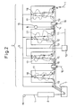
- FIG. 2 shows an outline of one embodiment of a hot dip plating system of the present invention.
- the hot dip plating system is comprised of, in order in the conveyance direction of the steel sheet 1, an annealing furnace 2 having a front heating zone 3, a rear heating zone 4, a soaking zone 5, and a cooling zone 6, a hot dip plating bath 7, and an alloying system 8.
- the zones 3, 4, 5, and 6 of the annealing furnace are provided with rollers 18 for continuously conveying the steel sheet. Openings 19 are provided between the zones to enable the steel sheet to pass through the zones in the furnace.
- the zones in the annealing furnace 2 are connected to atmospheric gas pipes 9 for introducing atmospheric gas comprised of hydrogen and nitrogen.
- Wet nitrogen is obtained by blowing into nitrogen gas from a nitrogen pipe 11 to a nitrogen wetting system 10 and travels through a wet nitrogen feed pipe 12 to be introduced to the rear heating zone 4 and soaking zone 5. Between the front heating zone 3 and the rear heating zone 4, an exhaust system 13 and a front heating zone sealing system 14 are provided. Further, between the soaking zone 5 and the cooling zone 6, a cooling zone sealing system 15 is provided. These sealing systems are connected to sealing use nitrogen pipes 16.
- a flow of gas in the annealing furnace is formed as shown schematically by the atmospheric gas flow 17, so even if introducing wet nitrogen resulting in dew points in the rear heating zone and soaking zone of -30°C or more, the flow of the high dew point atmosphere into the front heating zone or_cooling zone is greatly suppressed and as a result the dew points of the front heating zone and cooling zone can be maintained at less than -25°C.
- a steel sheet of each of the components shown in Table 1 was used as the plating sheet.
- the atmosphere in the annealing furnace was preadjusted to hydrogen 5% and the balance of nitrogen and unavoidable components, then in accordance with the plating conditions, wet nitrogen was introduced and the exhaust system and sealing system were operated to control the dew points in the different zones to -40°C to 5°C in range.
- the dew point in the cooling zone was made -30°C or less in all cases.
- the steel sheet temperature at the exit side of the front heating zone was controlled to 400°C to 780°C
- the steel sheet temperature at the exit side of the rear heating zone was controlled to 830°C to 850°C
- the steel sheet was held in the soaking zone for 75 seconds.
- the steel sheet temperature at the exit side of the cooling zone was made 465°C.
- the bath temperature was made 460°C
- the bath Al concentration was made 0.13%
- gas wiping was used to adjust the amount of plating deposition to 50 g/m 2 per side.
- the alloying conditions the alloying temperature was made 500°C and the sheet was held there for 30 seconds.
- the presence of any oxidation of the steel sheet during the heating and soaking was detected by using a radiant thermometer using a polarization type detection element to measure the emissivity of the steel sheet surface.
- a steel sheet When a steel sheet has no surface oxidation, it exhibits an emissivity of 0.20 to 0.30 or so, but the emissivity exhibits a higher value in accordance with the extent of oxidation of the steel sheet surface. This time, an emissivity of 0.33 or more was judged as indicating surface oxidation of the steel sheet.
- Such radiant thermometers were provided at the exit of the front heating zone, the center of the rear heating zone, the exit of the rear heating zone, and the exit of the soaking zone.
- the obtained plated steel sheet was evaluated for the presence of nonplating defects by inspection in the stopped state and for plating ability and alloying characteristics by measurement of the Fe concentration in the plating layer by sampling.
- the alloying characteristics a plating layer having an Fe concentration of less than 8% is judged as not yet alloyed, while one over 12% is judged as being excessively alloyed. The other layers are judged to have passed.
Abstract
Description
- The present invention relates to a continuous annealing and hot dip plating method and continuous annealing and hot dip plating system for steel sheet containing Si.
- Note that the hot dip plating in the present invention does not particularly specify the type of the plating metal and includes hot dip plating of zinc, aluminum, tin, or other metals and their alloys.
- When hot dip plating steel sheet with zinc, aluminum, tin, or another metal or their alloys, usually the surface of the steel sheet surface is degreased and cleaned, then the steel sheet is annealed by an annealing furnace, the steel sheet surface is activated by hydrogen reduction, the sheet is cooled to a predetermined temperature, then the sheet is dipped in a hot dip plating bath. With this method, when the components of the steel sheet include Si, Mn, and other easily oxidizable metals, during the annealing, these easily oxidizable elements form single or composite oxides at the steel sheet surface, obstruct the plating ability, and cause nonplating defects. Alternatively, when plating, then reheating for alloying, the alloying rate is lowered. Among these, Si forms an SiO2 oxide film on the steel sheet surface to remarkably lower the steel sheet and hot dip plating metal wettability. Simultaneously, the SiO2 oxide film forms a large barrier to diffusion between the iron metal and the plating metal at the time of alloying. Therefore, this is particularly a problem. To avoid this problem, it is sufficient to sharply lower the oxygen potential in the annealing atmosphere, but industrially obtaining an atmosphere in which Si, Mn, etc. will not oxidize is de facto impossible.
- To deal with this problem, Japanese Patent No.
2,618,308 2,648,772 - Further, Japanese Unexamined Patent Publication No.
2000-309824 - Further, Japanese Unexamined Patent Publication No.
2004-315960 - However, these prior arts have the following problems.
- Japanese Patent No.
2,618,308 2,648,772 - Japanese Unexamined Patent Publication No.
2000-309824 - Japanese Unexamined Patent Publication No.
2004-315960 - Therefore, an object of the present invention is to provide a system and method for hot dip plating steel sheet containing Si by an indirect heating system during which preventing the formation of surface oxides of the iron metal in the relatively low temperature range and causing the Si or Mn to internally oxidize and thereby avoid a drop in the plating ability of the steel sheet and retardation in alloying.
- The present invention was made to solve the above problem and has as its gist the following.
- (1) A continuous annealing and hot dip plating method for steel sheet containing Si using an annealing furnace having, in order in a direction of conveyance of steel sheet, a front heating zone, rear heating zone, soaking zone, and cooling zone and a hot dip plating bath provided at a rear of the same so as to continuously convey steel sheet to the annealing furnace and hot dip plating bath and continuously anneal and hot dip plate it, the continuous annealing and hot dip plating method characterized by heating or soaking the steel sheet at a steel sheet temperature of a temperature range of at least 300°C or more by indirect heating, making an atmosphere of the front heating zone, rear heating zone, soaking zone, and cooling zone one comprised of hydrogen in an amount of 1 to 10 vol% and a balance of nitrogen and unavoidable impurities, making a dew point of the front heating zone less than -25°C, making dew points of the rear heating zone and soaking zone -30°C to 0°C, making a dew point of the cooling zone less than -25°C, annealing with a steel sheet peak temperature during heating in the front heating zone 550 to 750°C, then hot dip plating the sheet.
- (2) A continuous annealing and hot dip plating method for steel sheet containing Si as set forth in (1), characterized by exhausting at least part of the atmospheric gas flowing from the front heating zone to the rear heating zone side between the front heating zone and the rear heating zone.
- (3) A continuous annealing and hot dip plating method for steel sheet containing Si as set forth in (2), characterized by sealing the atmosphere between the front heating zone and the atmospheric gas exhaust location.
- (4) A continuous annealing and hot dip plating method for steel sheet containing Si as set forth in any one of (1) to (3), characterized by sealing the atmosphere between the soaking zone and the cooling zone.
- (5) A continuous annealing and hot dip plating method for steel sheet containing Si as set forth in any one of (1) to (4), characterized by wetting and introducing a mixed gas of nitrogen and hydrogen to the rear heating zone and/or the soaking zone.
- (6) A continuous annealing and hot dip plating method for steel sheet containing Si as set forth in any one of (1) to (5), characterized by hot dip plating the steel sheet, then reheating it to 460°C or more to cause the plating layer to alloy with the iron metal.
- (7) A continuous annealing and hot dip plating system for steel sheet containing Si provided with an annealing furnace and a hot dip plating bath, loading a continuous steel sheet from a front of an annealing furnace, moving it continuously inside the furnace to anneal it, then taking it out from the furnace and then continuously hot dip plating it by the hot dip plating bath at the rear of the annealing furnace, the continuous annealing and hot dip plating system characterized in that the annealing furnace is provided with, in a direction of conveyance of the steel sheet, zones divided into a front heating zone, a rear heating zone, a soaking zone, and a cooling zone, each zone is provided with rollers for conveying the steel sheet and openings for continuously conveying the steel sheet between the zones, each zone has means for controlling a composition of an atmospheric gas and a dew point of the atmosphere, the front heating zone, rear heating zone, and soaking zone have indirect heating type steel sheet heating means, the front heating zone and rear heating zone have between them an atmospheric gas exhausting means for exhausting to the outside of the furnace at least part of the atmospheric gas flowing in from the front heating zone to the rear heating zone, and the atmospheric gas exhausting means and the front heating zone and/or the soaking zone and the cooling zone have between them an atmospheric gas sealing system.
- (8) A continuous annealing and hot dip plating system for steel sheet containing Si as set forth in (7), characterized by being provided with an alloying furnace provided with a heating means for reheating the plated steel sheet at the rear of the hot dip plating bath.
- According to the present invention, when heating steel sheet containing Si, the dew points of the heating zone and soaking zone are controlled to avoid the formation of Fe-based oxides at the steel sheet surface and the Si is made to internally oxidize so suppress the surface concentration of Si. Production of hot dip plated steel sheet superior in plating appearance and plating adhesion and production of alloyed hot dip plated steel sheet not requiring an extreme rise in the alloying temperature or a longer alloying time become possible.
-
-
FIG. 1 is a view illustrating a technique for forming internal oxides to avoid the formation of Fe-based oxides in the present invention. -
FIG. 2 is a view of the overall configuration of a hot dip plating system of the present invention. - The Si, Mn, and other easily oxidizable elements contained in steel sheet form single or composite oxides at the steel sheet surface, that is, are externally oxidized, under the atmospheric conditions of the annealing furnace used for a usual hot dip plating system, so cause the formation of nonplating defects due to the drop in the plating ability and a drop in the alloying speed in the alloying treatment after plating. If causing the Si, Mn, and other easily oxidizable elements to form oxides inside the steel sheet, that is, to be internally oxidized, the majority of the steel sheet surface will be occupied by Fe, so a drop in the plating ability or a drop in the alloying speed can be avoided. Such Si, Mn, or other sole or composite internal oxides are formed by making the atmosphere of the annealing furnace one comprised of hydrogen in an amount of 1 to 10% and nitrogen in 99 to 90%, having a dew point of -30°C to 0°C, and comprised of other unavoidable components and by heating the steel sheet to 550°C or more. If the dew point is less than -30°C, the external oxidation of the Si, Mn, etc. is insufficiently suppressed and the plating ability falls. On the other hand, if the dew point exceeds 0°C, internal oxides are formed, but simultaneously the iron metal is oxidized, so the plating ability drops due to the poor reduction of the Fe-based oxides. When heating to 550°C or more under atmospheric conditions suitable for the above internal oxidation, internal oxides are formed from the steel sheet surface down to 2 µm or less. If the internal oxides extend to a depth exceeding 2 µm from the steel sheet surface, due to heating at a high dew point under a high temperature for more than the necessary time etc., a large amount of internal oxides is formed. In this case, problems such as retardation of alloying arise.
- In the case of an annealing furnace employing direct-fired heating for the front stage of heating, the atmosphere of the direct-fired heating zone is mainly comprised of the exhaust gas of combustion of the burner. Due to the larger amount of water vapor contained in the combustion exhaust gas, oxidation of the iron metal is inevitable and, as explained above, the steel sheet is liable to be formed with impression defects due to the hearth rolls. Therefore, for the region where the steel sheet temperature becomes 300°C or more, where the steel sheet will substantially oxidize by a direct-fired heating system, an indirect heating system is suitably employed. However, the present invention does not concern itself with the heating method up to less than 300°C.
- Si, Mn, etc. start to oxidize from the heating stage of the annealing, so the above atmospheric conditions suitable for internal oxidation should be made the heating zone and soaking zone of the annealing furnace. However, if the dew point in the atmosphere becomes -25°C or more, Fe-based oxides will form on the steel sheet surface in the temperature range in the middle of the heating where the steel sheet temperature is relatively low. This type of oxide formed by the indirect heating system disappears in the later heating process, but remains even if the steel sheet temperature exceeds 550°C. In this case, the inventors discovered that it sticks to the rolls in the furnace and, like with the direct-fired heating system, causes impression defects on the steel sheet surface. To avoid this, the dew points at the front heating zone and cooling zone of the annealing furnace have to be made less than -25°C to avoid the formation of Fe-based surface oxides and the atmosphere of the rear heating zone or soaking zone has to be made one of conditions suitable for the internal oxidation. The front heating zone should have a steel sheet peak temperature of 550°C to 750°C. The lower limit temperature of the steel sheet peak temperature is made 550°C because even if Fe-based oxides are formed at the steel sheet surface, if less than 550°C, there is substantially no problem of them sticking to the hearth rolls and causing impression defects in the steel sheet. On the other hand, the upper limit temperature of the steel sheet peak temperature was made 750°C because if over 750°C, Si and Mn external oxides rapidly grow, so even if heating or soaking later in an atmosphere suitable for internal oxidation of Si or Mn and forming internal oxides, a good plating ability or alloying characteristics will no longer be able to be obtained.
- Note that the highest peak temperature in the annealing furnace is usually over 750°C, but the suitable temperature differs depending on the targeted strength level or steel components, so this is not defined here. Further, the cooling temperature of the steel sheet in the cooling zone usually is about the same extent as the plating bath temperature, but the suitable temperature differs depending on the type of plating, so this is not defined here.
- As the method for dividing the heating zone of an annealing furnace into front and rear zones, there is the method of providing a partition at a suitable position in the heating zone or separating the heating zone itself through a throat.
-
FIG. 1 illustrates the technique for forming internal oxides avoiding the formation of Fe-based oxides of the present invention explained above. A in the figure shows the limit of formation of Fe-based oxides and is near about 550°C. In a region of a temperature lower than this, Fe-based oxides are formed, while in a region of a temperature higher than this, Fe-based oxides are not formed and the Fe-based oxides formed at the low temperature side are reduced. B in the figure shows the upper limit of the dew point in the front heating zone according to the present invention and is near about - 25°C. Further, I in the figure shows the steel sheet heating pattern suitable when forming internal oxides at the lowest dew point of the present invention. Further, II in the figure shows the steel sheet heating pattern suitable when forming internal oxides at the highest dew point of the present invention. In each case, in the heating region where the steel sheet temperature becomes 550°C or more, no Fe-based oxides are formed. - Note that as the concentration of Si in the steel sheet for which this technology is effective, surface concentration of the Si causes the plating ability to drop creating a real problem at an Si concentration of 0.2 mass% or more. Further, if the Si concentration exceeds 2.5 mass%, the content of Si becomes too great and even if using this technology, it becomes hard to suppress surface concentration of the Si to a level not obstructing the plating ability. Therefore, a range of 0.2 to 2.5 mass% is preferable.
- Regarding the amount of addition of Mn, the suitable amount differs depending on the targeted strength level or steel structure, so this is not defined here.
- The atmospheric gas in the annealing furnace of the hot dip plating system usually flows from the plating bath side in the direction of the front heating zone. The majority is dispersed from the inlet of the heating zone to outside the furnace. Therefore, to separate the atmosphere, in particular the dew point, between the front and rear heating zones of the annealing furnace, the only option is to prevent the atmosphere of the high dew point soaking zone or rear heating zone from flowing into the front heating zone. There must be a system for exhausting part of the atmospheric gas flowing in from the rear heating zone to the front heating zone between the front and rear heating zones.
- Further, to improve the effect of preventing the flow of atmospheric gas of the soaking zone or rear heating zone to the front heating zone, it is effective to have a system for system for exhausting part of the atmospheric gas flowing in from the rear heating zone to the front heating zone between the front and rear heating zones and further to have a sealing system for suppressing the outflow of atmospheric gas of the front heating zone and inflow of atmospheric gas of the rear heating zone at the front side of the exhaust system.
- On the other hand, in the cooling zone at the rear from the heating zone or soaking zone, if the temperature of the steel sheet falls and the dew point becomes -25°C or more, an Fe-based oxide film is liable to be formed again at the steel sheet surface. Therefore, to keep the atmospheric gas of the heating zone or soaking zone from flowing in reverse to the subsequent cooling zone and realize the effect of improvement of the plating ability and alloying characteristics due to formation of suitable internal oxides, provision of a sealing system between the heating zone or soaking zone and the cooling zone is necessary.
- The atmosphere required for the effective formation of internal oxides is obtained by adjusting the flow rate of the usual nitrogen gas or hydrogen gas or mixed gas of the same to give the required composition and introducing it into the furnace and simultaneously introducing water vapor into the furnace. At this time, if directly introducing water vapor into the furnace, there will be the problem of deterioration of the uniformity of the dew point in the furnace and the problem that in the event of the high concentration water vapor directly contacting the steel sheet, useless oxides will be formed on the steel sheet surface, so the method of wetting and introducing nitrogen gas or a mixed gas of nitrogen and hydrogen is preferable. The nitrogen gas or mixed gas of nitrogen and hydrogen flowing into the furnace usually has a dew point of a low -40°C or less, but the gas may be run through warm water or warm water may be sprayed against the gas flow or another method is used to obtain wet gas containing saturated water vapor close to the temperature of the warm water. The amount of moisture contained in the wet gas is much smaller than that of water vapor itself. When the gas is introduced into the furnace, there is the advantage that a more uniform atmosphere may be quickly formed compared with blowing in water vapor.
- The atmosphere flowing in from the rear heating zone may be exhausted by for example a flow rate adjustment damper and an exhaust gas blower. Further, the sealing system installed at the front side of the exhaust gas system may be structured by for example a plurality of seal rolls, dampers, or baffle plates into which sealing use nitrogen is introduced. The sealing gas is partially exhausted by the exhaust system, but the atmosphere of the front heating zone is not exhausted much at all and the high dew point rear heating zone atmosphere can be kept from flowing into the front heating zone. The sealing system provided between the rear heating zone or soaking zone and the cooling zone may for example be structured in the same way as the sealing system provided at the front side of the exhaust gas system explained above, but the flow of gas in the annealing furnace is basically from the cooling zone side to the heating zone or soaking zone direction, so it is also possible not to introduce sealing use nitrogen.
- The thus obtained steel sheet is hot dip plated, then may be reheated to a steel sheet temperature of 460°C or more so as to cause the plating layer to alloy with the iron metal at a speed not causing problems industrially. An alloyed hot dip plated steel sheet containing Si which is free of nonplating defects can therefore be produced.
-
FIG. 2 shows an outline of one embodiment of a hot dip plating system of the present invention. In the present embodiment, the hot dip plating system is comprised of, in order in the conveyance direction of the steel sheet 1, an annealing furnace 2 having a front heating zone 3, a rear heating zone 4, a soaking zone 5, and a cooling zone 6, a hotdip plating bath 7, and an alloyingsystem 8. The zones 3, 4, 5, and 6 of the annealing furnace are provided withrollers 18 for continuously conveying the steel sheet.Openings 19 are provided between the zones to enable the steel sheet to pass through the zones in the furnace. The zones in the annealing furnace 2 are connected toatmospheric gas pipes 9 for introducing atmospheric gas comprised of hydrogen and nitrogen. Wet nitrogen is obtained by blowing into nitrogen gas from anitrogen pipe 11 to anitrogen wetting system 10 and travels through a wetnitrogen feed pipe 12 to be introduced to the rear heating zone 4 and soaking zone 5. Between the front heating zone 3 and the rear heating zone 4, anexhaust system 13 and a front heatingzone sealing system 14 are provided. Further, between the soaking zone 5 and the cooling zone 6, a coolingzone sealing system 15 is provided. These sealing systems are connected to sealinguse nitrogen pipes 16. By configuring the system in this way, a flow of gas in the annealing furnace is formed as shown schematically by theatmospheric gas flow 17, so even if introducing wet nitrogen resulting in dew points in the rear heating zone and soaking zone of -30°C or more, the flow of the high dew point atmosphere into the front heating zone or_cooling zone is greatly suppressed and as a result the dew points of the front heating zone and cooling zone can be maintained at less than -25°C. - Next, an example of use of the hot dip plating system of the present embodiment to hot dip galvanize an Si-containing steel sheet, then reheat it to produce alloyed hot dip galvanized steel sheet will be explained.
- For an experiment, a steel sheet of each of the components shown in Table 1 was used as the plating sheet. The atmosphere in the annealing furnace was preadjusted to hydrogen 5% and the balance of nitrogen and unavoidable components, then in accordance with the plating conditions, wet nitrogen was introduced and the exhaust system and sealing system were operated to control the dew points in the different zones to -40°C to 5°C in range. However, the dew point in the cooling zone was made -30°C or less in all cases. As the annealing conditions, the steel sheet temperature at the exit side of the front heating zone was controlled to 400°C to 780°C, the steel sheet temperature at the exit side of the rear heating zone was controlled to 830°C to 850°C, and the steel sheet was held in the soaking zone for 75 seconds. Further, the steel sheet temperature at the exit side of the cooling zone was made 465°C. As the conditions of the plating bath, the bath temperature was made 460°C, the bath Al concentration was made 0.13%, and gas wiping was used to adjust the amount of plating deposition to 50 g/m2 per side. As the alloying conditions, the alloying temperature was made 500°C and the sheet was held there for 30 seconds.
- The presence of any oxidation of the steel sheet during the heating and soaking was detected by using a radiant thermometer using a polarization type detection element to measure the emissivity of the steel sheet surface. When a steel sheet has no surface oxidation, it exhibits an emissivity of 0.20 to 0.30 or so, but the emissivity exhibits a higher value in accordance with the extent of oxidation of the steel sheet surface. This time, an emissivity of 0.33 or more was judged as indicating surface oxidation of the steel sheet. Such radiant thermometers were provided at the exit of the front heating zone, the center of the rear heating zone, the exit of the rear heating zone, and the exit of the soaking zone.
- The obtained plated steel sheet was evaluated for the presence of nonplating defects by inspection in the stopped state and for plating ability and alloying characteristics by measurement of the Fe concentration in the plating layer by sampling. Regarding the alloying characteristics, a plating layer having an Fe concentration of less than 8% is judged as not yet alloyed, while one over 12% is judged as being excessively alloyed. The other layers are judged to have passed.
- The obtained results are as shown in Table 2. For all of the types of steel containing Si, by making the steel sheet temperature at the exit side of the front heating zone 550°C to 750°C, making the dew point of the front heating zone less than -25°C, and making the dew points of the rear heating zone and soaking zone -30°C to 0°C, surface oxidation of the steel sheet in the annealing furnace could be avoided and alloyed hot dip plated steel sheet with good plating ability and alloying characteristics could be obtained.
Table 1 Steel type Steel components (mass%) C Si Mn P S Al Ti B Ni A 0.004 0.3 1.2 0.060 0.006 0.050 0.09 0.003 - B 0.1 0.5 1.6 0.008 0.003 0.025 - - - C 0.1 1.25 1.6 0.007 0.005 0.25 - - - D 0.12 1.2 1.1 0.009 0.007 0.32 - - 0.6 E 0.11 1.8 1.58 0.008 0.003 0.30 - - - Table 2 Steel type Front heating zone exit temperature °C Dew point Steel sheet quality Remarks Front heating zone °C Rear heating zone °C Soaking zone °C Steel sheet oxidation Nonplating defects Alloying A 550 -40 -25 -30 No No Pass Invention B 600 -15 -15 -15 Yes No Pass Comp. ex. B 550 -35 -20 -22 No No Pass Invention B 650 -28 -25 -22 No No Pass Invention C 600 -30 5 5 Yes Yes Fail Comp. ex. C 600 -35 -25 -25 No No Pass Invention C 500 -40 -40 -40 No Yes Fail Comp. ex. D 700 -25 -10 -10 No No Pass Invention D 600 -35 -20 -25 No No Pass Invention D 400 -30 -15 -15 Yes No Pass Comp. ex. E 780 -30 -20 -20 No Yes Fail Comp. ex. E 650 -30 -20 -20 No No Pass Invention E 720 -35 -5 -5 No No Pass Invention
Claims (8)
- A continuous annealing and hot dip plating method for steel sheet containing Si using an annealing furnace having, in order in a direction of conveyance of steel sheet, a front heating zone, rear heating zone, soaking zone, and cooling zone and a hot dip plating bath provided at a rear of the same so as to continuously convey steel sheet to the annealing furnace and hot dip plating bath and continuously anneal and hot dip plate it, said continuous annealing and hot dip plating method characterized by heating or soaking the steel sheet at a steel sheet temperature of a temperature range of at least 300°C or more by indirect heating, making an atmosphere of the front heating zone, rear heating zone, soaking zone, and cooling zone one comprised of hydrogen in an amount of 1 to 10 vol% and a balance of nitrogen and unavoidable impurities, making a dew point of the front heating zone less than -25°C, making dew points of the rear heating zone and soaking zone -30°C to 0°C, making a dew point of the cooling zone less than -25°C, annealing with a steel sheet peak temperature during heating in the front heating zone 550 to 750°C, then hot dip plating the sheet.
- A continuous annealing and hot dip plating method for steel sheet containing Si as set forth in claim 1, characterized by exhausting at least part of the atmospheric gas flowing from said front heating zone to said rear heating zone side between said front heating zone and said rear heating zone.
- A continuous annealing and hot dip plating method for steel sheet containing Si as set forth in claim 2, characterized by sealing the atmosphere between said front heating zone and said atmospheric gas exhaust location.
- A continuous annealing and hot dip plating method for steel sheet containing Si as set forth in any one of claims 1 to 3, characterized by sealing the atmosphere between said soaking zone and said cooling zone.
- A continuous annealing and hot dip plating method for steel sheet containing Si as set forth in any one of claims 1 to 4, characterized by wetting and introducing a mixed gas of nitrogen and hydrogen to said rear heating zone and/or said soaking zone.
- A continuous annealing and hot dip plating method for steel sheet containing Si as set forth in any one of claims 1 to 5, characterized by hot dip plating the steel sheet, then reheating it to 460°C or more to cause the plating layer to alloy with the iron metal.
- A continuous annealing and hot dip plating system for steel sheet containing Si provided with an annealing furnace and a hot dip plating bath, loading a continuous steel sheet from a front of an annealing furnace, moving it continuously inside the furnace to anneal it, then taking it out from the furnace and then continuously hot dip plating it by the hot dip plating bath at the rear of the annealing furnace, said continuous annealing and hot dip plating system characterized in that said annealing furnace is provided with, in a direction of conveyance of the steel sheet, zones divided into a front heating zone, a rear heating zone, a soaking zone, and a cooling zone, each zone is provided with rollers for conveying the steel sheet and openings for continuously conveying the steel sheet between the zones, each zone has means for controlling a composition of an atmospheric gas and a dew point of the atmosphere, the front heating zone, rear heating zone, and soaking zone have indirect heating type steel sheet heating means, the front heating zone and rear heating zone have between them an atmospheric gas exhausting means for exhausting to the outside of the furnace at least part of the atmospheric gas flowing in from the front heating zone to the rear heating zone, and the atmospheric gas exhausting means and the front heating zone and/or said soaking zone and said cooling zone have between them an atmospheric gas sealing system.
- A continuous annealing and hot dip plating system for steel sheet containing Si as set forth in claim 7, characterized by being provided with an alloying furnace provided with a heating means for reheating the plated steel sheet at the rear of said hot dip plating bath.
Applications Claiming Priority (2)
| Application Number | Priority Date | Filing Date | Title |
|---|---|---|---|
| JP2005299915 | 2005-10-14 | ||
| PCT/JP2006/318089 WO2007043273A1 (en) | 2005-10-14 | 2006-09-06 | Method of continuous annealing/hot-dipping of steel sheet containing silicon and apparatus for continuous annealing/hot-dipping |
Publications (3)
| Publication Number | Publication Date |
|---|---|
| EP1936000A1 true EP1936000A1 (en) | 2008-06-25 |
| EP1936000A4 EP1936000A4 (en) | 2010-03-10 |
| EP1936000B1 EP1936000B1 (en) | 2018-06-27 |
Family
ID=37942528
Family Applications (1)
| Application Number | Title | Priority Date | Filing Date |
|---|---|---|---|
| EP06797881.7A Active EP1936000B1 (en) | 2005-10-14 | 2006-09-06 | Continuous annealing and hot-dipping plating method and system for steel sheets containing silicon |
Country Status (10)
| Country | Link |
|---|---|
| US (1) | US20090123651A1 (en) |
| EP (1) | EP1936000B1 (en) |
| JP (1) | JP4791482B2 (en) |
| KR (1) | KR101011897B1 (en) |
| CN (1) | CN101287854B (en) |
| BR (1) | BRPI0617390B1 (en) |
| CA (1) | CA2625790C (en) |
| RU (1) | RU2387734C2 (en) |
| TW (1) | TWI302571B (en) |
| WO (1) | WO2007043273A1 (en) |
Cited By (15)
| Publication number | Priority date | Publication date | Assignee | Title |
|---|---|---|---|---|
| WO2009030823A1 (en) * | 2007-09-03 | 2009-03-12 | Siemens Vai Metals Technologies Sas | Controlled method and device for oxidation/reduction of the surface of a steel strip running continuously through a radiant tube oven for galvanisation thereof |
| DE102011051731A1 (en) | 2011-07-11 | 2013-01-17 | Thyssenkrupp Steel Europe Ag | Process for the preparation of a flat steel product provided by hot dip coating with a metallic protective layer |
| WO2013117273A1 (en) * | 2012-02-08 | 2013-08-15 | Thyssenkrupp Steel Europe Ag | Process for the hot dip coating of a flat steel product |
| EP2824216A1 (en) | 2013-05-24 | 2015-01-14 | ThyssenKrupp Steel Europe AG | Method for manufacturing a flat steel product having a protective metal coating produced by means of hot-dip coating and continuous furnace for a hot-dip coating system |
| US20150167113A1 (en) * | 2012-06-13 | 2015-06-18 | Jfe Steel Corporation | Method for continuously annealing steel strip, apparatus for continuously annealing steel strip, method for manufacturing hot-dip galvanized steel strip, and apparatus for manufacturing hot-dip galvanized steel strip |
| EP2862947A4 (en) * | 2012-06-13 | 2015-07-15 | Jfe Steel Corp | Method of continuous annealing of steel strip, and method of manufacturing hot-dip galvanized steel strip |
| EP2623631A4 (en) * | 2010-09-30 | 2016-11-23 | Jfe Steel Corp | High-strength steel sheet and method for producing same |
| EP3168321A4 (en) * | 2014-07-07 | 2017-05-31 | JFE Steel Corporation | Production method for alloyed hot-dip-galvanized steel sheet |
| US9713823B2 (en) | 2012-04-06 | 2017-07-25 | Jfe Steel Corporation | Continuous galvanizing line having an annealing furnace |
| EP3243924A4 (en) * | 2015-01-08 | 2017-11-15 | JFE Steel Corporation | Method of producing galvannealed steel sheet |
| EP3206509A4 (en) * | 2014-10-13 | 2018-06-27 | The State of Israel, Ministry of Agriculture and Rural Development, Agricultural Research Organisation, Volcani Center | Method and system for treating a product |
| US10053749B2 (en) * | 2008-12-26 | 2018-08-21 | Posco | Production method for plated steel sheet using a steel sheet annealing device |
| EP3369836A4 (en) * | 2015-10-27 | 2018-11-07 | JFE Steel Corporation | Method for manufacturing hot-dip galvanized steel sheet |
| EP3511430A1 (en) * | 2018-01-12 | 2019-07-17 | SMS Group GmbH | Method for a continuous heat treatment of a steel strip, and installation for dip coating a steel strip |
| WO2022130124A1 (en) * | 2020-12-15 | 2022-06-23 | Arcelormittal | Annealing method |
Families Citing this family (55)
| Publication number | Priority date | Publication date | Assignee | Title |
|---|---|---|---|---|
| EP2009128A1 (en) * | 2007-06-29 | 2008-12-31 | ArcelorMittal France | Galvanized or galvannealed silicon steel |
| JP5555992B2 (en) * | 2008-09-05 | 2014-07-23 | Jfeスチール株式会社 | Manufacturing method of high-strength hot-dip galvanized steel sheet with excellent surface appearance and plating adhesion |
| JP5672747B2 (en) * | 2009-03-31 | 2015-02-18 | Jfeスチール株式会社 | High-strength hot-dip galvanized steel sheet and manufacturing method thereof |
| JP5672745B2 (en) * | 2009-03-31 | 2015-02-18 | Jfeスチール株式会社 | High-strength hot-dip galvanized steel sheet and manufacturing method thereof |
| JP5672746B2 (en) * | 2009-03-31 | 2015-02-18 | Jfeスチール株式会社 | High-strength hot-dip galvanized steel sheet and manufacturing method thereof |
| JP5672744B2 (en) * | 2009-03-31 | 2015-02-18 | Jfeスチール株式会社 | High-strength hot-dip galvanized steel sheet and manufacturing method thereof |
| JP5206705B2 (en) * | 2009-03-31 | 2013-06-12 | Jfeスチール株式会社 | High-strength hot-dip galvanized steel sheet and manufacturing method thereof |
| ES2876258T3 (en) * | 2009-12-29 | 2021-11-12 | Posco | Zinc Plated Hot Pressed Parts and Production Procedure |
| JP5636683B2 (en) * | 2010-01-28 | 2014-12-10 | 新日鐵住金株式会社 | High-strength galvannealed steel sheet with excellent adhesion and manufacturing method |
| JP5533000B2 (en) * | 2010-02-15 | 2014-06-25 | 新日鐵住金株式会社 | Method for producing galvannealed steel sheet |
| CN101781745A (en) * | 2010-03-19 | 2010-07-21 | 杭州创宇金属制品科技有限公司 | Steel wire and steel strip hot-dip zero-emission energy-saving production system and production method |
| JP2011224584A (en) * | 2010-04-16 | 2011-11-10 | Jfe Steel Corp | Method of manufacturing hot-rolled steel sheet and method of manufacturing hot-dip galvanized steel sheet |
| DE102010017354A1 (en) * | 2010-06-14 | 2011-12-15 | Thyssenkrupp Steel Europe Ag | Process for producing a hot-formed and hardened steel component coated with a metallic anti-corrosion coating from a flat steel product |
| JP5716338B2 (en) * | 2010-09-29 | 2015-05-13 | Jfeスチール株式会社 | High strength steel plate and manufacturing method thereof |
| JP5609494B2 (en) * | 2010-09-29 | 2014-10-22 | Jfeスチール株式会社 | High strength steel plate and manufacturing method thereof |
| JP5760361B2 (en) * | 2010-09-29 | 2015-08-12 | Jfeスチール株式会社 | High strength steel plate and manufacturing method thereof |
| EP2623630B1 (en) * | 2010-09-30 | 2020-07-01 | JFE Steel Corporation | Method for producing high-strength steel sheet |
| TWI609086B (en) * | 2010-09-30 | 2017-12-21 | 杰富意鋼鐵股份有限公司 | High strength steel sheet and method for manufacturing the same |
| TWI491741B (en) * | 2010-09-30 | 2015-07-11 | Jfe Steel Corp | High strength steel sheet and method for manufacturing the same |
| JP5071551B2 (en) | 2010-12-17 | 2012-11-14 | Jfeスチール株式会社 | Continuous annealing method for steel strip, hot dip galvanizing method |
| CN102816986A (en) * | 2011-06-10 | 2012-12-12 | 宝山钢铁股份有限公司 | Strip steel continuous hot galvanizing method |
| KR101428151B1 (en) | 2011-12-27 | 2014-08-08 | 주식회사 포스코 | Zn-coated hot rolled steel sheet having high mn and method for manufacturing the same |
| JP5505430B2 (en) | 2012-01-17 | 2014-05-28 | Jfeスチール株式会社 | Continuous annealing furnace and continuous annealing method for steel strip |
| MX2014012798A (en) * | 2012-04-23 | 2015-04-14 | Kobe Steel Ltd | Method for producing galvanized steel sheet for hot stamping, alloyed hot-dipped galvanized steel sheet for hot stamping and method for producing same, and hot stamped component. |
| JP5505461B2 (en) | 2012-05-24 | 2014-05-28 | Jfeスチール株式会社 | Continuous annealing furnace for steel strip, continuous annealing method for steel strip, continuous hot dip galvanizing equipment and method for manufacturing hot dip galvanized steel strip |
| JP5510495B2 (en) | 2012-05-24 | 2014-06-04 | Jfeスチール株式会社 | Continuous annealing furnace for steel strip, continuous annealing method, continuous hot dip galvanizing equipment and manufacturing method of hot dip galvanized steel strip |
| JP5971155B2 (en) * | 2012-10-11 | 2016-08-17 | Jfeスチール株式会社 | Method for producing high-strength hot-dip galvanized steel sheet and high-strength hot-dip galvanized steel sheet |
| EP2927342A4 (en) * | 2012-12-04 | 2016-01-06 | Jfe Steel Corp | Facility and method for manufacturing continuous hot-dip zinc-coated steel sheet |
| JP5884748B2 (en) | 2013-02-25 | 2016-03-15 | Jfeスチール株式会社 | Steel strip continuous annealing equipment and continuous hot dip galvanizing equipment |
| JP5565485B1 (en) | 2013-02-25 | 2014-08-06 | Jfeスチール株式会社 | Steel strip continuous annealing equipment and continuous hot dip galvanizing equipment |
| WO2015068369A1 (en) | 2013-11-07 | 2015-05-14 | Jfeスチール株式会社 | Continuous annealing equipment and continuous annealing method |
| EP4215628A1 (en) * | 2013-12-10 | 2023-07-26 | Arcelormittal S.A. | A method of annealing steel sheets |
| MX2016010931A (en) | 2014-02-25 | 2016-11-18 | Jfe Steel Corp | Method for controlling dew point of reduction furnace, and reduction furnace. |
| TWI586834B (en) * | 2014-03-21 | 2017-06-11 | China Steel Corp | Method of Hot - dip Galvanizing for Si - Mn High Strength Steel |
| JP6008007B2 (en) * | 2015-03-23 | 2016-10-19 | Jfeスチール株式会社 | Continuous hot dip galvanizing apparatus and method for producing hot dip galvanized steel sheet |
| JP6269547B2 (en) * | 2015-03-23 | 2018-01-31 | Jfeスチール株式会社 | Continuous hot dip galvanizing apparatus and method for producing hot dip galvanized steel sheet |
| EA035895B1 (en) * | 2015-04-22 | 2020-08-27 | Кокрий Ментенанс Эт Энженьери С.А. | Method and device for reaction control |
| EP3170913A1 (en) * | 2015-11-20 | 2017-05-24 | Cockerill Maintenance & Ingenierie S.A. | Method and device for reaction control |
| WO2017154494A1 (en) * | 2016-03-11 | 2017-09-14 | Jfeスチール株式会社 | Production method for high-strength hot-dip galvanized steel sheet |
| JP6237937B2 (en) * | 2016-03-11 | 2017-11-29 | Jfeスチール株式会社 | Method for producing high-strength hot-dip galvanized steel sheet |
| WO2017182833A1 (en) * | 2016-04-19 | 2017-10-26 | Arcelormittal | Method for producing a metallic coated steel sheet |
| KR102557715B1 (en) | 2016-05-10 | 2023-07-20 | 유나이테드 스테이츠 스틸 코포레이션 | Annealing process for high-strength steel products and their manufacture |
| US11560606B2 (en) | 2016-05-10 | 2023-01-24 | United States Steel Corporation | Methods of producing continuously cast hot rolled high strength steel sheet products |
| KR102231412B1 (en) | 2016-10-25 | 2021-03-23 | 제이에프이 스틸 가부시키가이샤 | Manufacturing method of high-strength hot-dip galvanized steel sheet |
| CN107419074B (en) * | 2017-04-27 | 2019-06-04 | 山东钢铁集团日照有限公司 | A kind of process for eliminating cold rolling coil corrosion defect |
| JP6455544B2 (en) | 2017-05-11 | 2019-01-23 | Jfeスチール株式会社 | Method for producing hot-dip galvanized steel sheet |
| CN106995876B (en) * | 2017-05-26 | 2018-05-15 | 鞍钢蒂森克虏伯(重庆)汽车钢有限公司 | A kind of annealing furnace humidifier pipe-line system and its operating method |
| WO2019092467A1 (en) * | 2017-11-08 | 2019-05-16 | Arcelormittal | A galvannealed steel sheet |
| EP3730662B1 (en) | 2017-12-22 | 2021-11-17 | JFE Steel Corporation | Method for producing hot-dip galvanized steel sheet and continuous hot-dip galvanizing apparatus |
| CN109988893A (en) * | 2019-04-26 | 2019-07-09 | 宝钢湛江钢铁有限公司 | A kind of continuous annealing process for reducing nano-oxide and generating |
| CN110904327B (en) * | 2019-11-29 | 2021-07-23 | 北京首钢冷轧薄板有限公司 | Galvanizing unit, zinc ash defect control method, device and system thereof and storage medium |
| CN115003847A (en) * | 2020-02-21 | 2022-09-02 | 杰富意钢铁株式会社 | Method for manufacturing high-strength hot-dip galvanized steel sheet |
| WO2021224662A1 (en) * | 2020-05-07 | 2021-11-11 | Arcelormittal | Annealing method of steel |
| DE102020208991A1 (en) * | 2020-07-17 | 2022-01-20 | Thyssenkrupp Steel Europe Ag | Process for producing a hot-dip coated steel sheet and hot-dip coated steel sheet |
| EP4353861A1 (en) | 2021-07-14 | 2024-04-17 | JFE Steel Corporation | Method for producing hot-dip galvanized steel sheet |
Citations (6)
| Publication number | Priority date | Publication date | Assignee | Title |
|---|---|---|---|---|
| US4053663A (en) * | 1972-08-09 | 1977-10-11 | Bethlehem Steel Corporation | Method of treating ferrous strand for coating with aluminum-zinc alloys |
| US4584211A (en) * | 1983-08-17 | 1986-04-22 | Nippon Steel Corporation | Continuous hot dip aluminum coating method |
| EP0467749A1 (en) * | 1990-07-16 | 1992-01-22 | Sollac | Method of hot dip aluminium coating of a ferritic stainless steel strip |
| EP0995807A1 (en) * | 1998-10-23 | 2000-04-26 | Kawasaki Steel Corporation | Sealing apparatus in continuous heat-treatment furnace and sealing method |
| US20030091857A1 (en) * | 2001-11-15 | 2003-05-15 | Bethlehem Steel Corporation | Method for coating a steel alloy and a product therefrom |
| JP2003342645A (en) * | 2002-05-30 | 2003-12-03 | Jfe Steel Kk | In-line annealing furnace for continuous hot-dip galvanizing |
Family Cites Families (17)
| Publication number | Priority date | Publication date | Assignee | Title |
|---|---|---|---|---|
| US2656285A (en) * | 1948-06-03 | 1953-10-20 | Armco Steel Corp | Production of coated soft iron and steel sheets |
| US2875113A (en) * | 1957-11-15 | 1959-02-24 | Gen Electric | Method of decarburizing silicon steel in a wet inert gas atmosphere |
| US3056694A (en) * | 1958-07-11 | 1962-10-02 | Inland Steel Co | Galvanizing process |
| US3333987A (en) * | 1964-12-02 | 1967-08-01 | Inland Steel Co | Carbon-stabilized steel products and method of making the same |
| US3532329A (en) * | 1968-11-01 | 1970-10-06 | Selas Corp Of America | Strip heating apparatus |
| JPH0336214A (en) * | 1989-07-01 | 1991-02-15 | Nkk Corp | Method for continuously annealing non-oriented electrical steel sheet |
| JP2649753B2 (en) * | 1991-11-06 | 1997-09-03 | 新日本製鐵株式会社 | Partition structure of continuous gas processing furnace with different atmosphere |
| JPH0625817A (en) * | 1992-07-10 | 1994-02-01 | Kobe Steel Ltd | Production of hot-dip galvanized cold rolled steel sheet having high strength and excellent in adhesion of plating film |
| JP3220362B2 (en) * | 1995-09-07 | 2001-10-22 | 川崎製鉄株式会社 | Manufacturing method of grain-oriented silicon steel sheet |
| JP2001288550A (en) * | 2000-01-31 | 2001-10-19 | Kobe Steel Ltd | Galvanized steel sheet |
| WO2002022893A1 (en) * | 2000-09-12 | 2002-03-21 | Kawasaki Steel Corporation | High tensile strength hot dip plated steel sheet and method for production thereof |
| FR2828888B1 (en) * | 2001-08-21 | 2003-12-12 | Stein Heurtey | METHOD FOR HOT GALVANIZATION OF HIGH STRENGTH STEEL METAL STRIPS |
| EP1587966B1 (en) * | 2003-01-15 | 2017-05-17 | Nippon Steel & Sumitomo Metal Corporation | High-strength hot-dip galvanized steel sheet and method for producing the same |
| JP3997931B2 (en) * | 2003-03-04 | 2007-10-24 | Jfeスチール株式会社 | Method for producing high-tensile hot-dip galvanized steel sheet |
| KR20070122581A (en) * | 2003-04-10 | 2007-12-31 | 신닛뽄세이테쯔 카부시키카이샤 | Hot-dip zinc coated steel sheet having high strength and method for production thereof |
| JP4192051B2 (en) * | 2003-08-19 | 2008-12-03 | 新日本製鐵株式会社 | Manufacturing method and equipment for high-strength galvannealed steel sheet |
| JP4306427B2 (en) * | 2003-11-27 | 2009-08-05 | Jfeスチール株式会社 | Alloyed hot-dip galvanized steel sheet and method for producing the same |
-
2006
- 2006-09-06 KR KR1020087008625A patent/KR101011897B1/en active IP Right Grant
- 2006-09-06 WO PCT/JP2006/318089 patent/WO2007043273A1/en active Application Filing
- 2006-09-06 US US12/083,396 patent/US20090123651A1/en not_active Abandoned
- 2006-09-06 CA CA2625790A patent/CA2625790C/en active Active
- 2006-09-06 RU RU2008118883/02A patent/RU2387734C2/en active
- 2006-09-06 BR BRPI0617390-0A patent/BRPI0617390B1/en active IP Right Grant
- 2006-09-06 EP EP06797881.7A patent/EP1936000B1/en active Active
- 2006-09-06 JP JP2007539836A patent/JP4791482B2/en active Active
- 2006-09-06 CN CN2006800382692A patent/CN101287854B/en active Active
- 2006-09-11 TW TW095133446A patent/TWI302571B/en active
Patent Citations (6)
| Publication number | Priority date | Publication date | Assignee | Title |
|---|---|---|---|---|
| US4053663A (en) * | 1972-08-09 | 1977-10-11 | Bethlehem Steel Corporation | Method of treating ferrous strand for coating with aluminum-zinc alloys |
| US4584211A (en) * | 1983-08-17 | 1986-04-22 | Nippon Steel Corporation | Continuous hot dip aluminum coating method |
| EP0467749A1 (en) * | 1990-07-16 | 1992-01-22 | Sollac | Method of hot dip aluminium coating of a ferritic stainless steel strip |
| EP0995807A1 (en) * | 1998-10-23 | 2000-04-26 | Kawasaki Steel Corporation | Sealing apparatus in continuous heat-treatment furnace and sealing method |
| US20030091857A1 (en) * | 2001-11-15 | 2003-05-15 | Bethlehem Steel Corporation | Method for coating a steel alloy and a product therefrom |
| JP2003342645A (en) * | 2002-05-30 | 2003-12-03 | Jfe Steel Kk | In-line annealing furnace for continuous hot-dip galvanizing |
Non-Patent Citations (1)
| Title |
|---|
| See also references of WO2007043273A1 * |
Cited By (26)
| Publication number | Priority date | Publication date | Assignee | Title |
|---|---|---|---|---|
| EP2188399B2 (en) † | 2007-09-03 | 2023-05-03 | Primetals Technologies USA LLC | Controlled method and device for oxidation/reduction of the surface of a steel strip running continuously through a radiant tube oven for galvanisation thereof |
| US8609192B2 (en) | 2007-09-03 | 2013-12-17 | Siemens Vai Metals Technologies Sas | Method and device for controlling oxidizing-reducing of the surface of a steel strip running continuously through a radiant tubes furnace for its galvanizing |
| WO2009030823A1 (en) * | 2007-09-03 | 2009-03-12 | Siemens Vai Metals Technologies Sas | Controlled method and device for oxidation/reduction of the surface of a steel strip running continuously through a radiant tube oven for galvanisation thereof |
| US10053749B2 (en) * | 2008-12-26 | 2018-08-21 | Posco | Production method for plated steel sheet using a steel sheet annealing device |
| EP2623631A4 (en) * | 2010-09-30 | 2016-11-23 | Jfe Steel Corp | High-strength steel sheet and method for producing same |
| DE102011051731A1 (en) | 2011-07-11 | 2013-01-17 | Thyssenkrupp Steel Europe Ag | Process for the preparation of a flat steel product provided by hot dip coating with a metallic protective layer |
| WO2013007578A2 (en) | 2011-07-11 | 2013-01-17 | Thyssenkrupp Steel Europe Ag | Method for producing a flat steel product which is provided with a metallic protective layer by means of hot dip coating |
| DE102011051731B4 (en) * | 2011-07-11 | 2013-01-24 | Thyssenkrupp Steel Europe Ag | Process for the preparation of a flat steel product provided by hot dip coating with a metallic protective layer |
| US9096919B2 (en) | 2011-07-11 | 2015-08-04 | Thyssenkrupp Steel Europe Ag | Method for producing a flat steel product provided with a metal protective layer by way of hot dip coating |
| WO2013117273A1 (en) * | 2012-02-08 | 2013-08-15 | Thyssenkrupp Steel Europe Ag | Process for the hot dip coating of a flat steel product |
| US9803270B2 (en) | 2012-02-08 | 2017-10-31 | Thyssenkrupp Steel Europe Ag | Method for hot-dip coating of a steel flat product |
| US9713823B2 (en) | 2012-04-06 | 2017-07-25 | Jfe Steel Corporation | Continuous galvanizing line having an annealing furnace |
| EP2862947A4 (en) * | 2012-06-13 | 2015-07-15 | Jfe Steel Corp | Method of continuous annealing of steel strip, and method of manufacturing hot-dip galvanized steel strip |
| US20150167113A1 (en) * | 2012-06-13 | 2015-06-18 | Jfe Steel Corporation | Method for continuously annealing steel strip, apparatus for continuously annealing steel strip, method for manufacturing hot-dip galvanized steel strip, and apparatus for manufacturing hot-dip galvanized steel strip |
| US10590509B2 (en) * | 2012-06-13 | 2020-03-17 | Jfe Steel Corporation | Method for continuously annealing steel strip, apparatus for continuously annealing steel strip, method for manufacturing hot-dip galvanized steel strip, and apparatus for manufacturing hot-dip galvanized steel strip |
| US10106867B2 (en) | 2012-06-13 | 2018-10-23 | Jfe Steel Corporation | Method for continuously annealing steel strip and method for manufacturing galvanized steel strip |
| EP2824216A1 (en) | 2013-05-24 | 2015-01-14 | ThyssenKrupp Steel Europe AG | Method for manufacturing a flat steel product having a protective metal coating produced by means of hot-dip coating and continuous furnace for a hot-dip coating system |
| US10752975B2 (en) | 2014-07-07 | 2020-08-25 | Jfe Steel Corporation | Method of producing galvannealed steel sheet |
| EP3168321A4 (en) * | 2014-07-07 | 2017-05-31 | JFE Steel Corporation | Production method for alloyed hot-dip-galvanized steel sheet |
| EP3206509A4 (en) * | 2014-10-13 | 2018-06-27 | The State of Israel, Ministry of Agriculture and Rural Development, Agricultural Research Organisation, Volcani Center | Method and system for treating a product |
| US10645941B2 (en) | 2014-10-13 | 2020-05-12 | The State Of Israel, Ministry Of Agriculture & Rural Development, Agricultural Research Organization (Aro) (Volcani Center) | Method and system for treating a product |
| EP3243924A4 (en) * | 2015-01-08 | 2017-11-15 | JFE Steel Corporation | Method of producing galvannealed steel sheet |
| EP3369836A4 (en) * | 2015-10-27 | 2018-11-07 | JFE Steel Corporation | Method for manufacturing hot-dip galvanized steel sheet |
| EP3511430A1 (en) * | 2018-01-12 | 2019-07-17 | SMS Group GmbH | Method for a continuous heat treatment of a steel strip, and installation for dip coating a steel strip |
| WO2022130124A1 (en) * | 2020-12-15 | 2022-06-23 | Arcelormittal | Annealing method |
| WO2022129989A1 (en) * | 2020-12-15 | 2022-06-23 | Arcelormittal | Annealing method |
Also Published As
| Publication number | Publication date |
|---|---|
| EP1936000A4 (en) | 2010-03-10 |
| TW200714718A (en) | 2007-04-16 |
| EP1936000B1 (en) | 2018-06-27 |
| WO2007043273A1 (en) | 2007-04-19 |
| JPWO2007043273A1 (en) | 2009-04-16 |
| CN101287854A (en) | 2008-10-15 |
| KR20080046241A (en) | 2008-05-26 |
| CA2625790A1 (en) | 2007-04-19 |
| US20090123651A1 (en) | 2009-05-14 |
| TWI302571B (en) | 2008-11-01 |
| KR101011897B1 (en) | 2011-02-01 |
| JP4791482B2 (en) | 2011-10-12 |
| CA2625790C (en) | 2010-10-12 |
| BRPI0617390A2 (en) | 2011-07-26 |
| RU2387734C2 (en) | 2010-04-27 |
| BRPI0617390B1 (en) | 2017-12-05 |
| RU2008118883A (en) | 2009-11-20 |
| CN101287854B (en) | 2011-04-20 |
Similar Documents
| Publication | Publication Date | Title |
|---|---|---|
| EP1936000B1 (en) | Continuous annealing and hot-dipping plating method and system for steel sheets containing silicon | |
| JP7330104B2 (en) | Method for producing steel strip with aluminum alloy coating layer | |
| KR101303337B1 (en) | Method for hot dip coating a strip of heavy-duty steel | |
| US8491734B2 (en) | Process of production and production system of high strength galvannealed steel sheet | |
| JP7095804B2 (en) | Manufacturing method of high-strength hot-dip galvanized steel sheet | |
| JP6025867B2 (en) | High-strength hot-dip galvanized steel sheet excellent in plating surface quality and plating adhesion and method for producing the same | |
| EP2956296B1 (en) | Coated steel suitable for hot-dip galvanising | |
| JP5130733B2 (en) | Continuous annealing equipment | |
| JP5799819B2 (en) | Method for producing hot-dip galvanized steel sheet with excellent plating wettability and pick-up resistance | |
| CN101466860A (en) | Method for continuously annealing and preparing strip of high-strength steel for the purpose of hot-dip galvanizing it | |
| CN111676350A (en) | Method for annealing steel sheet | |
| JP4797601B2 (en) | High strength hot dip galvanized steel sheet manufacturing method and hot dip galvanized steel sheet manufacturing equipment | |
| JP7243668B2 (en) | Method for manufacturing cold-rolled steel sheet and hot-dip galvanized steel sheet | |
| JP3176843B2 (en) | Manufacturing method and manufacturing equipment for hot-dip galvanized steel sheet | |
| KR101428151B1 (en) | Zn-coated hot rolled steel sheet having high mn and method for manufacturing the same | |
| KR101500282B1 (en) | Method for manufacturing high strength galvanized steel sheet having excellent surface property and coating adhesion | |
| JP6740973B2 (en) | Method for manufacturing hot-dip galvanized steel sheet | |
| JP6696495B2 (en) | Method for manufacturing hot dip galvanized steel sheet | |
| WO2024014372A1 (en) | Method for heating steel plate, method for producing plated steel plate, direct-fired heating furnace, and continuous hot-dip galvanizing equipment | |
| JP2005200711A (en) | Method of producing hot dip galvannealed steel sheet | |
| JP5831218B2 (en) | Method for producing hot-dip galvanized steel sheet | |
| JP2004270020A (en) | Method for producing galvanized steel sheet and galvannealed steel sheet |
Legal Events
| Date | Code | Title | Description |
|---|---|---|---|
| PUAI | Public reference made under article 153(3) epc to a published international application that has entered the european phase |
Free format text: ORIGINAL CODE: 0009012 |
|
| 17P | Request for examination filed |
Effective date: 20080325 |
|
| AK | Designated contracting states |
Kind code of ref document: A1 Designated state(s): AT BE BG CH CY CZ DE DK EE ES FI FR GB GR HU IE IS IT LI LT LU LV MC NL PL PT RO SE SI SK TR |
|
| A4 | Supplementary search report drawn up and despatched |
Effective date: 20100210 |
|
| DAX | Request for extension of the european patent (deleted) | ||
| RAP1 | Party data changed (applicant data changed or rights of an application transferred) |
Owner name: NIPPON STEEL & SUMITOMO METAL CORPORATION |
|
| 17Q | First examination report despatched |
Effective date: 20130305 |
|
| GRAP | Despatch of communication of intention to grant a patent |
Free format text: ORIGINAL CODE: EPIDOSNIGR1 |
|
| INTG | Intention to grant announced |
Effective date: 20180108 |
|
| GRAS | Grant fee paid |
Free format text: ORIGINAL CODE: EPIDOSNIGR3 |
|
| GRAA | (expected) grant |
Free format text: ORIGINAL CODE: 0009210 |
|
| AK | Designated contracting states |
Kind code of ref document: B1 Designated state(s): AT BE BG CH CY CZ DE DK EE ES FI FR GB GR HU IE IS IT LI LT LU LV MC NL PL PT RO SE SI SK TR |
|
| REG | Reference to a national code |
Ref country code: GB Ref legal event code: FG4D |
|
| REG | Reference to a national code |
Ref country code: AT Ref legal event code: REF Ref document number: 1012418 Country of ref document: AT Kind code of ref document: T Effective date: 20180715 |
|
| REG | Reference to a national code |
Ref country code: FR Ref legal event code: PLFP Year of fee payment: 13 |
|
| REG | Reference to a national code |
Ref country code: IE Ref legal event code: FG4D |
|
| REG | Reference to a national code |
Ref country code: DE Ref legal event code: R096 Ref document number: 602006055703 Country of ref document: DE |
|
| PG25 | Lapsed in a contracting state [announced via postgrant information from national office to epo] |
Ref country code: LT Free format text: LAPSE BECAUSE OF FAILURE TO SUBMIT A TRANSLATION OF THE DESCRIPTION OR TO PAY THE FEE WITHIN THE PRESCRIBED TIME-LIMIT Effective date: 20180627 Ref country code: FI Free format text: LAPSE BECAUSE OF FAILURE TO SUBMIT A TRANSLATION OF THE DESCRIPTION OR TO PAY THE FEE WITHIN THE PRESCRIBED TIME-LIMIT Effective date: 20180627 Ref country code: BG Free format text: LAPSE BECAUSE OF FAILURE TO SUBMIT A TRANSLATION OF THE DESCRIPTION OR TO PAY THE FEE WITHIN THE PRESCRIBED TIME-LIMIT Effective date: 20180927 Ref country code: SE Free format text: LAPSE BECAUSE OF FAILURE TO SUBMIT A TRANSLATION OF THE DESCRIPTION OR TO PAY THE FEE WITHIN THE PRESCRIBED TIME-LIMIT Effective date: 20180627 |
|
| REG | Reference to a national code |
Ref country code: NL Ref legal event code: MP Effective date: 20180627 |
|
| REG | Reference to a national code |
Ref country code: LT Ref legal event code: MG4D |
|
| PG25 | Lapsed in a contracting state [announced via postgrant information from national office to epo] |
Ref country code: GR Free format text: LAPSE BECAUSE OF FAILURE TO SUBMIT A TRANSLATION OF THE DESCRIPTION OR TO PAY THE FEE WITHIN THE PRESCRIBED TIME-LIMIT Effective date: 20180928 Ref country code: LV Free format text: LAPSE BECAUSE OF FAILURE TO SUBMIT A TRANSLATION OF THE DESCRIPTION OR TO PAY THE FEE WITHIN THE PRESCRIBED TIME-LIMIT Effective date: 20180627 |
|
| REG | Reference to a national code |
Ref country code: AT Ref legal event code: MK05 Ref document number: 1012418 Country of ref document: AT Kind code of ref document: T Effective date: 20180627 |
|
| PG25 | Lapsed in a contracting state [announced via postgrant information from national office to epo] |
Ref country code: NL Free format text: LAPSE BECAUSE OF FAILURE TO SUBMIT A TRANSLATION OF THE DESCRIPTION OR TO PAY THE FEE WITHIN THE PRESCRIBED TIME-LIMIT Effective date: 20180627 |
|
| PG25 | Lapsed in a contracting state [announced via postgrant information from national office to epo] |
Ref country code: CZ Free format text: LAPSE BECAUSE OF FAILURE TO SUBMIT A TRANSLATION OF THE DESCRIPTION OR TO PAY THE FEE WITHIN THE PRESCRIBED TIME-LIMIT Effective date: 20180627 Ref country code: RO Free format text: LAPSE BECAUSE OF FAILURE TO SUBMIT A TRANSLATION OF THE DESCRIPTION OR TO PAY THE FEE WITHIN THE PRESCRIBED TIME-LIMIT Effective date: 20180627 Ref country code: SK Free format text: LAPSE BECAUSE OF FAILURE TO SUBMIT A TRANSLATION OF THE DESCRIPTION OR TO PAY THE FEE WITHIN THE PRESCRIBED TIME-LIMIT Effective date: 20180627 Ref country code: PL Free format text: LAPSE BECAUSE OF FAILURE TO SUBMIT A TRANSLATION OF THE DESCRIPTION OR TO PAY THE FEE WITHIN THE PRESCRIBED TIME-LIMIT Effective date: 20180627 Ref country code: AT Free format text: LAPSE BECAUSE OF FAILURE TO SUBMIT A TRANSLATION OF THE DESCRIPTION OR TO PAY THE FEE WITHIN THE PRESCRIBED TIME-LIMIT Effective date: 20180627 Ref country code: EE Free format text: LAPSE BECAUSE OF FAILURE TO SUBMIT A TRANSLATION OF THE DESCRIPTION OR TO PAY THE FEE WITHIN THE PRESCRIBED TIME-LIMIT Effective date: 20180627 Ref country code: IS Free format text: LAPSE BECAUSE OF FAILURE TO SUBMIT A TRANSLATION OF THE DESCRIPTION OR TO PAY THE FEE WITHIN THE PRESCRIBED TIME-LIMIT Effective date: 20181027 |
|
| PG25 | Lapsed in a contracting state [announced via postgrant information from national office to epo] |
Ref country code: ES Free format text: LAPSE BECAUSE OF FAILURE TO SUBMIT A TRANSLATION OF THE DESCRIPTION OR TO PAY THE FEE WITHIN THE PRESCRIBED TIME-LIMIT Effective date: 20180627 |
|
| REG | Reference to a national code |
Ref country code: DE Ref legal event code: R097 Ref document number: 602006055703 Country of ref document: DE |
|
| PG25 | Lapsed in a contracting state [announced via postgrant information from national office to epo] |
Ref country code: MC Free format text: LAPSE BECAUSE OF FAILURE TO SUBMIT A TRANSLATION OF THE DESCRIPTION OR TO PAY THE FEE WITHIN THE PRESCRIBED TIME-LIMIT Effective date: 20180627 |
|
| REG | Reference to a national code |
Ref country code: CH Ref legal event code: PL |
|
| PLBE | No opposition filed within time limit |
Free format text: ORIGINAL CODE: 0009261 |
|
| STAA | Information on the status of an ep patent application or granted ep patent |
Free format text: STATUS: NO OPPOSITION FILED WITHIN TIME LIMIT |
|
| PG25 | Lapsed in a contracting state [announced via postgrant information from national office to epo] |
Ref country code: DK Free format text: LAPSE BECAUSE OF FAILURE TO SUBMIT A TRANSLATION OF THE DESCRIPTION OR TO PAY THE FEE WITHIN THE PRESCRIBED TIME-LIMIT Effective date: 20180627 |
|
| 26N | No opposition filed |
Effective date: 20190328 |
|
| REG | Reference to a national code |
Ref country code: DE Ref legal event code: R082 Ref document number: 602006055703 Country of ref document: DE Representative=s name: VOSSIUS & PARTNER PATENTANWAELTE RECHTSANWAELT, DE Ref country code: DE Ref legal event code: R081 Ref document number: 602006055703 Country of ref document: DE Owner name: NIPPON STEEL CORPORATION, JP Free format text: FORMER OWNER: NIPPON STEEL & SUMITOMO METAL CORPORATION, TOKYO, JP |
|
| REG | Reference to a national code |
Ref country code: BE Ref legal event code: MM Effective date: 20180930 |
|
| REG | Reference to a national code |
Ref country code: IE Ref legal event code: MM4A |
|
| PG25 | Lapsed in a contracting state [announced via postgrant information from national office to epo] |
Ref country code: LU Free format text: LAPSE BECAUSE OF NON-PAYMENT OF DUE FEES Effective date: 20180906 |
|
| PG25 | Lapsed in a contracting state [announced via postgrant information from national office to epo] |
Ref country code: IE Free format text: LAPSE BECAUSE OF NON-PAYMENT OF DUE FEES Effective date: 20180906 |
|
| PG25 | Lapsed in a contracting state [announced via postgrant information from national office to epo] |
Ref country code: CH Free format text: LAPSE BECAUSE OF NON-PAYMENT OF DUE FEES Effective date: 20180930 Ref country code: BE Free format text: LAPSE BECAUSE OF NON-PAYMENT OF DUE FEES Effective date: 20180930 Ref country code: SI Free format text: LAPSE BECAUSE OF FAILURE TO SUBMIT A TRANSLATION OF THE DESCRIPTION OR TO PAY THE FEE WITHIN THE PRESCRIBED TIME-LIMIT Effective date: 20180627 Ref country code: LI Free format text: LAPSE BECAUSE OF NON-PAYMENT OF DUE FEES Effective date: 20180930 |
|
| PG25 | Lapsed in a contracting state [announced via postgrant information from national office to epo] |
Ref country code: TR Free format text: LAPSE BECAUSE OF FAILURE TO SUBMIT A TRANSLATION OF THE DESCRIPTION OR TO PAY THE FEE WITHIN THE PRESCRIBED TIME-LIMIT Effective date: 20180627 |
|
| PG25 | Lapsed in a contracting state [announced via postgrant information from national office to epo] |
Ref country code: HU Free format text: LAPSE BECAUSE OF FAILURE TO SUBMIT A TRANSLATION OF THE DESCRIPTION OR TO PAY THE FEE WITHIN THE PRESCRIBED TIME-LIMIT; INVALID AB INITIO Effective date: 20060906 Ref country code: PT Free format text: LAPSE BECAUSE OF FAILURE TO SUBMIT A TRANSLATION OF THE DESCRIPTION OR TO PAY THE FEE WITHIN THE PRESCRIBED TIME-LIMIT Effective date: 20180627 |
|
| PG25 | Lapsed in a contracting state [announced via postgrant information from national office to epo] |
Ref country code: CY Free format text: LAPSE BECAUSE OF FAILURE TO SUBMIT A TRANSLATION OF THE DESCRIPTION OR TO PAY THE FEE WITHIN THE PRESCRIBED TIME-LIMIT Effective date: 20180627 |
|
| PGFP | Annual fee paid to national office [announced via postgrant information from national office to epo] |
Ref country code: IT Payment date: 20230810 Year of fee payment: 18 Ref country code: GB Payment date: 20230727 Year of fee payment: 18 |
|
| PGFP | Annual fee paid to national office [announced via postgrant information from national office to epo] |
Ref country code: FR Payment date: 20230808 Year of fee payment: 18 Ref country code: DE Payment date: 20230802 Year of fee payment: 18 |