EP3511274A1 - Static pressure control method in automatic winder and automatic winder - Google Patents
Static pressure control method in automatic winder and automatic winder Download PDFInfo
- Publication number
- EP3511274A1 EP3511274A1 EP18212232.5A EP18212232A EP3511274A1 EP 3511274 A1 EP3511274 A1 EP 3511274A1 EP 18212232 A EP18212232 A EP 18212232A EP 3511274 A1 EP3511274 A1 EP 3511274A1
- Authority
- EP
- European Patent Office
- Prior art keywords
- static pressure
- set value
- suction
- yarn
- frequency
- Prior art date
- Legal status (The legal status is an assumption and is not a legal conclusion. Google has not performed a legal analysis and makes no representation as to the accuracy of the status listed.)
- Granted
Links
Images





Classifications
-
- B—PERFORMING OPERATIONS; TRANSPORTING
- B65—CONVEYING; PACKING; STORING; HANDLING THIN OR FILAMENTARY MATERIAL
- B65H—HANDLING THIN OR FILAMENTARY MATERIAL, e.g. SHEETS, WEBS, CABLES
- B65H54/00—Winding, coiling, or depositing filamentary material
- B65H54/70—Other constructional features of yarn-winding machines
- B65H54/707—Suction generating system
-
- B—PERFORMING OPERATIONS; TRANSPORTING
- B65—CONVEYING; PACKING; STORING; HANDLING THIN OR FILAMENTARY MATERIAL
- B65H—HANDLING THIN OR FILAMENTARY MATERIAL, e.g. SHEETS, WEBS, CABLES
- B65H54/00—Winding, coiling, or depositing filamentary material
- B65H54/02—Winding and traversing material on to reels, bobbins, tubes, or like package cores or formers
- B65H54/10—Winding and traversing material on to reels, bobbins, tubes, or like package cores or formers for making packages of specified shapes or on specified types of bobbins, tubes, cores, or formers
- B65H54/20—Winding and traversing material on to reels, bobbins, tubes, or like package cores or formers for making packages of specified shapes or on specified types of bobbins, tubes, cores, or formers forming multiple packages
-
- B—PERFORMING OPERATIONS; TRANSPORTING
- B65—CONVEYING; PACKING; STORING; HANDLING THIN OR FILAMENTARY MATERIAL
- B65H—HANDLING THIN OR FILAMENTARY MATERIAL, e.g. SHEETS, WEBS, CABLES
- B65H54/00—Winding, coiling, or depositing filamentary material
- B65H54/02—Winding and traversing material on to reels, bobbins, tubes, or like package cores or formers
- B65H54/22—Automatic winding machines, i.e. machines with servicing units for automatically performing end-finding, interconnecting of successive lengths of material, controlling and fault-detecting of the running material and replacing or removing of full or empty cores
-
- B—PERFORMING OPERATIONS; TRANSPORTING
- B65—CONVEYING; PACKING; STORING; HANDLING THIN OR FILAMENTARY MATERIAL
- B65H—HANDLING THIN OR FILAMENTARY MATERIAL, e.g. SHEETS, WEBS, CABLES
- B65H63/00—Warning or safety devices, e.g. automatic fault detectors, stop-motions ; Quality control of the package
-
- B—PERFORMING OPERATIONS; TRANSPORTING
- B65—CONVEYING; PACKING; STORING; HANDLING THIN OR FILAMENTARY MATERIAL
- B65H—HANDLING THIN OR FILAMENTARY MATERIAL, e.g. SHEETS, WEBS, CABLES
- B65H67/00—Replacing or removing cores, receptacles, or completed packages at paying-out, winding, or depositing stations
- B65H67/08—Automatic end-finding and material-interconnecting arrangements
- B65H67/081—Automatic end-finding and material-interconnecting arrangements acting after interruption of the winding process, e.g. yarn breakage, yarn cut or package replacement
-
- B—PERFORMING OPERATIONS; TRANSPORTING
- B65—CONVEYING; PACKING; STORING; HANDLING THIN OR FILAMENTARY MATERIAL
- B65H—HANDLING THIN OR FILAMENTARY MATERIAL, e.g. SHEETS, WEBS, CABLES
- B65H2701/00—Handled material; Storage means
- B65H2701/30—Handled filamentary material
- B65H2701/31—Textiles threads or artificial strands of filaments
Definitions
- the present invention relates to a static pressure control method in an automatic winder including a plurality of winding units capable of carrying out a yarn joining operation using a suction airflow.
- An automatic winder including a plurality of winding units adapted to wind a yarn unwound from a yarn supplying bobbin around a bobbin to form a package.
- Each winding unit is provided with a yarn joining device adapted to join a yarn disconnected between the yarn supplying bobbin and the package.
- a suction member for an upper yarn adapted to suck and hold a yarn (upper yarn) from the package and a suction member for a lower yarn adapted to suck and hold a yarn (lower yarn) from the yarn supplying bobbin guide the upper yarn and the lower yarn to the yarn joining device, respectively.
- a suction blower adapted to supply the suction airflow is provided on the suction member of each winding unit.
- Yarn waste accumulates with elapse of time in a flow path connecting the suction blower and each winding unit, and thus the flow of suction air becomes unsatisfactory, and the pressure (static pressure) in a duct gradually lowers.
- the static pressure lowers, the suction force of the suction member lowers, and thus the yarn joining operation cannot be carried out.
- the static pressure may be set high from the beginning in view of the static pressure lowering, but in this case, the power consumption of the suction blower increases.
- Japanese Laid-Open Utility Model Publication No. 2-40759 discloses a method of detecting the static pressure of the suction airflow and feedback controlling the operation of the suction blower based on the detection value to maintain the static pressure constant while suppressing the increase in power consumption.
- the operation of the suction blower is merely feedback controlled, the following problems arise.
- a long time is required to match the static pressure of the suction airflow to the set value, and the power consumption at the beginning of the startup may increase.
- the static pressure may become higher than the set value as the static pressure of the suction airflow hunches (vibrates), which may become a cause of increase in power consumption.
- a first aspect of a static pressure control method in an automatic winder relates to a static pressure control method in an automatic winder including a plurality of winding units adapted to carry out a yarn joining operation using a suction airflow, a suction blower adapted to generate the suction airflow, and a static pressure detecting section adapted to detect a static pressure of the suction airflow, the static pressure control method including a startup process of activating the suction blower so that a static pressure of the suction airflow becomes higher than a predetermined set value at a time of startup of the plurality of winding units; an initial feedback process of feedback controlling a frequency of the suction blower to lower the static pressure of the suction airflow to the set value after the startup process; and a normal feedback process of feedback controlling the frequency of the suction blower to maintain the static pressure of the suction airflow at the set value after the initial feedback process, wherein a control period in the initial feedback process is shorter than a control period in the normal feedback process.
- the plurality of winding units are started up in order from the winding unit arranged at the end, and each winding unit starts the winding after the yarn joining operation.
- the yarn joining operation may continuously fail, and the winding may not be started.
- the suction blower is activated so that the static pressure of the suction airflow becomes higher than the set value in the startup process, the static pressure at the time of startup can be increased, and the yarn joining operation can be reliably carried out.
- the static pressure set high in the startup process is rapidly lowered to the set value to match the set value. Therefore, a state in which the static pressure is higher than the set value is only for a short time, and the power consumption of the suction blower can be reduced.
- a detection period by the static pressure detecting section in the initial feedback process is preferably shorter than a detection period in the normal feedback process.
- the static pressure can be more rapidly matched to the set value by shortening the detection period of the static pressure in the initial feedback process.
- an acceleration/deceleration rate of the frequency of the suction blower in the initial feedback process is preferably larger than an acceleration/deceleration rate in the normal feedback process.
- the static pressure set high in the startup process can be rapidly lowered to the set value by increasing the acceleration/deceleration rate of the frequency of the suction blower in the initial feedback process.
- a frequency of the suction blower is first accelerated, and when an instantaneous value of the static pressure detected by the static pressure detecting section becomes higher than or equal to a startup set value set higher than the set value, a frequency of the suction blower at a time point when the instantaneous value becomes higher than or equal to the startup set value is maintained thereafter.
- the frequency of the suction blower does not need to be changed after the instantaneous value of the static pressure reached the startup set value, and a simple control program can be obtained.
- the process preferably shifts to the initial feedback process after the startup of the plurality of winding units is completed in the startup process.
- a state in which the static pressure is high can be maintained while sequentially starting up the plurality of winding units by shifting to the initial feedback process after the startup of the plurality of winding units is completed. Therefore, the yarn joining operation can be effectively prevented from failing in the startup process, and the winding can be rapidly started.
- the frequency of the suction blower is preferably maintained at a frequency of a time point the frequency of the suction blower becomes smaller than or equal to the set value during the remaining of the control period.
- a second aspect of a static pressure control method in an automatic winder relates to a static pressure control method in an automatic winder including a plurality of winding units adapted to carry out a yarn joining operation using a suction airflow, a suction blower adapted to generate the suction airflow, and a static pressure detecting section adapted to detect a static pressure of the suction airflow, the static pressure control method including the steps of feedback controlling a frequency of the suction blower to maintain a static pressure of the suction airflow at a predetermined set value; starting to accelerate the frequency of the suction blower when a time average value of the static pressure detected by the static pressure detecting section is smaller than the set value; and stopping the acceleration of the frequency of the suction blower at a time point when an instantaneous value of the static pressure detected by the static pressure detecting section becomes higher than or equal to the set value.
- the determination of when to stop the acceleration of the frequency of the suction blower is made with the instantaneous value instead of the time average value of the static pressure, whereby the static pressure can be effectively prevented from rising beyond the set value and the power consumption of the suction blower can be reduced.
- An automatic winder includes a plurality of winding units adapted to carry out a yarn joining operation using a suction airflow; a suction blower adapted to generate the suction airflow; a static pressure detecting section adapted to detect a static pressure of the suction airflow; and a control section adapted to control operation of the suction blower based on the static pressure detected by the static pressure detecting section, wherein the control section executes any static pressure control method in the automatic winder described above.
- the power consumption of the suction blower can be reduced in the automatic winder including such a control section.
- FIG. 1 is a front view of an automatic winder according to the present embodiment
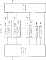
- FIG. 2 is a block diagram illustrating an electrical configuration of the automatic winder
- FIG. 3 is a front view of a winding unit.
- the automatic winder 1 includes a plurality of winding units 2 arrayed in a predetermined array direction (left and right direction of FIG. 1 ), a doffing device 3 arranged to freely travel in the left and right direction, a yarn waste collecting box 4 arranged on the left side of the plurality of winding units 2, and a machine control device 5 adapted to control each section.
- the machine control device 5, a unit control section 2a of each winding unit 2, and the doffing device 3 are configured to be able to transmit/receive electric signals with each other.
- a winding complete signal is transmitted from the unit control section 2a of the relevant winding unit 2 to the doffing device 3.
- the doffing device 3 that received the winding complete signal moves to the relevant winding unit 2 to carry out the doffing operation.
- the winding unit 2 winds a yarn Y unwound from a yarn supplying bobbin B around a winding tube Q to form the package P.
- the winding unit 2 includes a yarn supplying section 10 adapted to supply the yarn Y wound around the yarn supplying bobbin B while unwinding, a yarn processing section 20 adapted to carry out various processes on the yarn Y supplied from the yarn supplying section 10, and a winding section 30 adapted to wind the yarn Y that passed the yarn processing section 20 around the winding tube Q to form the package P.
- the yarn supplying section 10, the yarn processing section 20, and the winding section 30 are arranged in such order from the bottom to the top.
- the yarn supplying section 10 includes a yarn unwinding assisting device 11 adapted to assist the unwinding of the yarn Y when unwinding the yarn Y from the yarn supplying bobbin B held in a standing state.
- the yarn unwinding assisting device 11 includes a regulation tube 12 adapted to regulate the bulge (balloon) of when the yarn Y is being unwound to an appropriate range.
- the yarn processing section 20 includes a yarn filler 21, a tension applying device 22, a yarn joining device 23, a yarn clearer 24, a lower yarn catching and guiding member 25, an upper yarn catching and guiding member 26, and the like.
- the yarn filler 21 is adapted to detect the presence and absence of the travelling yarn Y between the yarn unwinding assisting device 11 and the tension applying device 22.
- the tension applying device 22 is adapted to apply a predetermined tension on the travelling yarn Y.
- a so-called gate type tension applying device is illustrated by way of example.
- the yarn clearer 24 acquires the information on the thickness of the travelling yarn Y on a steady basis, and detects an abnormal portion, where a yarn thickness is thick or greater than or equal to a constant thickness, included in the yarn Y as a yarn defect based on the information on the yarn thickness.
- a cutter 24a is arranged in the yarn clearer 24, where the yarn Y is immediately cut with the cutter 24a when the yarn defect is detected by the yarn clearer 24.
- the yarn joining device 23 joins a lower yarn Y1 from the yarn supplying bobbin B and an upper yarn Y2 from the package P when the yarn defect is detected by the yarn clearer 24 and the yarn is cut by the cutter 24a, when yarn breakage occurs during the winding of the package P, or when replacing the yarn supplying bobbin B.
- An example of the yarn joining device 23 is a splicer adapted to generate an airflow to entangle the fibers of the lower yarn Y1 and the upper yarn Y2 and carry out the yarn joining operation.
- the yarn defect remains in the upper yarn Y2 even if the yarn Y is cut by the cutter 24a after the yarn defect detection by the yarn clearer 24.
- the yarn joining device 23 carries out the yarn joining operation of the lower yarn Y1 and the upper yarn Y2 after removing the yarn defect using a built-in cutter (not illustrated).
- the lower yarn catching and guiding member 25 sucks and catches the lower yarn Y1 from the yarn supplying bobbin B and guides the lower yarn Y1 to the yarn joining device 23.
- the lower yarn catching and guiding member 25 is rotationally driven by a motor 27 to pivot up and down with a shaft 25a as the center.
- a distal end portion of the lower yarn catching and guiding member 25 is provided with a suction portion 25b adapted to suck and catch a yarn end of the lower yarn Y1.
- the upper yarn catching and guiding member 26 sucks and catches the upper yarn Y2 from the package P and guides the upper yarn Y2 to the yarn joining device 23.
- the upper yarn catching and guiding member 26 is rotationally driven by the motor 28 to pivot up and down with a shaft 26a as the center.
- a distal end portion of the upper yarn catching and guiding member 26 is provided with a suction portion 26b adapted to suck and catch a yarn end of the upper yarn Y2.
- the lower yarn catching and guiding member 25 and the upper yarn catching and guiding member 26 are connected to the yarn waste collecting device 6 (see FIG. 4 ), to be described later, and configured to generate suction airflow at the suction portion 25b, 26b.
- the yarn joining operation in the winding unit 2 is carried out in the following manner.
- the upper yarn catching and guiding member 26 first pivots upward, and sucks and catches the yarn end of the upper yarn Y2 attached to the surface of the package P with the suction portion 26b. Then, the upper yarn catching and guiding member 26 pivots downward while catching the upper yarn Y2 to guide the upper yarn Y2 to the yarn joining device 23.
- the lower yarn catching and guiding member 25 pivots upward while catching the yarn end of the lower yarn Y1 with the suction portion 25b to guide the lower yarn Y1 to the yarn joining device 23.
- the yarn joining device 23 then connects the yarn end of the lower yarn Y1 introduced by the lower yarn catching and guiding member 25 and the yarn end of the upper yarn Y2 introduced by the upper yarn catching and guiding member 26 to form one yarn Y.
- the winding section 30 includes a cradle 31, which supports the winding tube Q in a freely rotating manner, a traverse drum 32, and a drum drive motor 33 adapted to rotate the traverse drum 32.
- a spiral-shaped traverse groove 32a is formed on a peripheral surface of the traverse drum 32, which traverse groove 32a traverses the yarn Y.
- FIG. 4 is a top view schematically illustrating the yarn waste collecting device 6.
- the yarn waste collecting device 6 collects the yarn waste produced in the plurality of winding units 2.
- the yarn waste collecting device 6 includes a yarn waste collecting box 4, a suction blower 41 and a filter 42 arranged in the yarn waste collecting box 4, and a duct 43 that connects the yarn waste collecting box 4 and the plurality of winding units 2.
- the duct 43 is arranged behind the plurality of winding units 2.
- the duct 43 is provided with a static pressure sensor 46 adapted to detect the static pressure of the suction airflow in the duct 43.
- the static pressure sensor 46 is provided at an upstream end of the duct 43 in a direction the suction airflow flows.
- the static pressure sensor 46 may be provided at other portions of the duct 43, and may be provided on the duct 43 side than the filter 42 in an interior space of the yarn waste collecting box 4.
- the upper yarn catching and guiding member 26 of the winding unit 2 is connected to the duct 43 by way of a piping 51.
- the piping 51 is provided with a shutter 52, which operation is controlled by the unit control section 2a.
- the upper yarn catching and guiding member 26 can be switched to a state of acting the suction airflow and a state of not acting the suction airflow by opening and closing the shutter 52.
- the yarn Y can be sucked by the upper yarn catching and guiding member 26 by opening the shutter 52.
- the lower yarn catching and guiding member 25 is connected to the duct 43 by way of a piping 53.
- An open/close lid (not illustrated) is provided at the suction portion 25b (see FIG.
- the open/close lid makes contact with a pushing member (not illustrated) at a lower yarn catching position where the lower yarn catching and guiding member 25 catches the yarn end of the lower yarn Y1.
- the open/close lid thereby opens, and the suction action can be made.
- the static pressure (suction force) of the suction airflow in the duct 43 is desirably maintained at a predetermined set value P1.
- a frequency (rotation number) of the suction blower 41 is feedback controlled based on the detection value of the static pressure sensor 46 so as to maintain the static pressure in the duct 43 to the set value P1.
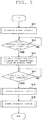
- FIG. 5 is a flowchart illustrating a series of operations after the startup of the automatic winder 1
- FIG. 6 is a flowchart illustrating an initial feedback control
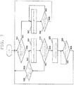
- FIG. 7 is a flowchart illustrating a normal feedback control
- FIG. 8 is a graph illustrating change in blower frequency and static pressure.
- a vertical line of a chain line illustrated in the graph of FIG. 8 indicates the start time of the control period of the feedback control, and an interval of the chain lines corresponds to the control period.
- fine vibration is typically generated at the instantaneous value (detection value itself) of the static pressure.
- the machine control device 5 first accelerates the frequency of the suction blower 41 (hereinafter referred to as "blower frequency") at the startup of the automatic winder 1 (see step S11, time t0 to t1 of FIG. 8 ).
- the acceleration of the blower frequency is stopped when the instantaneous value (detection value itself) of the static pressure (force per unit area acting in a perpendicular direction with respect to the direction of flow, hereinafter referred to as "static pressure") of the suction airflow in the duct 43 becomes higher than or equal to a predetermined startup set value P2 (YES in step S12, see time t1 of FIG. 8 ).
- Step S11 to S13 correspond to "startup process" of the present invention.
- the startup set value P2 is set to a value higher than the set value P1 in the initial feedback process and the normal feedback process, to be described later.
- the static pressure is made higher in the startup process than at the time of the normal operation because the yarn joining operation is simultaneously executed in a great number of winding units 2 when sequentially starting up the plurality of winding units 2. Even if the yarn joining operation is simultaneously executed in a great number of winding units 2 by making the static pressure in the startup process high, the deficiency in the suction force can be prevented from occurring.
- the machine control device 5 executes the initial feedback control to rapidly lower the static pressure made higher than the set value P1 in the startup process to the set value P1 (step S15).
- the initial feedback control is executed during time t2 to t4 of FIG. 8 , and corresponds to the "initial feedback process" of the present invention.
- the machine control device 5 executes the normal feedback control to maintain the static pressure to the set value P1 (step S16).
- the normal feedback control is executed after time t4 of FIG. 8 , and corresponds to the "normal feedback process" of the present invention.
- the initial feedback control and the normal feedback control will be hereinafter described in detail.
- step S21 whether or not a time average value (hereinafter referred to as "average value") of the static pressure in the control period one before is higher than the set value P1 is first determined (step S21).
- the average value of the static pressure is higher than the set value P1 (YES in step S21), and thus the blower frequency decelerates at a constant deceleration rate (step S22).
- the instantaneous value of the static pressure is detected at an interval shorter than the control period by the static pressure sensor 46. As illustrated in time t2 to t3 of FIG.
- step S23 whether or not the instantaneous value of the static pressure detected by the static pressure sensor 46 lowered to lower than or equal to the set value P1 is determined.
- the instantaneous value is still higher than the set value P1 (NO in step S23), and the control period has not elapsed (NO in step S24)
- the deceleration of the blower frequency is continued (step S22).
- the control period has elapsed (YES in step S24)
- the process returns to step S21 and the next control period is started based on the new average value.
- step S23 when the instantaneous value of the static pressure becomes lower than or equal to the set value P1 (YES in step S23, see time t3 of FIG. 8 ), the deceleration of the blower frequency is stopped and maintained constant during the remaining of the control period (step S25).
- step S26 When the control period has elapsed (YES in step S26), the process returns to step S21 and the next control period is started based on the new average value.
- the static pressure can be prevented from becoming too low beyond the set value P1 and the matching with the set value P1 can be rapidly carried out by determining the stop timing of the deceleration of the blower frequency with the instantaneous value instead of the average value of the static pressure.
- the initial feedback control is terminated and the process shifts to the normal feedback control.
- the shift is made to the normal feedback process at time t3.
- the shift is made to the normal feedback process of long control period, as will be described later, in a state where the average value of the static pressure is higher than the set value P1. In this case, a long time may be required to match the static pressure to the set value P1, and thus the determination of the shift is made with the average value rather than the instantaneous value in the present embodiment.
- the control period in the initial feedback control is made shorter than the control period in the normal feedback control described next. Furthermore, the detection period of the static pressure by the static pressure sensor 46 in the initial feedback control is made shorter than the detection period in the normal feedback control. Furthermore, the acceleration/deceleration rate of the blower frequency in the initial feedback control is made larger than the acceleration/deceleration rate of the blower frequency in the normal feedback control. In this manner, the static pressure can be rapidly matched with the set value P1 in the initial feedback process. In the present embodiment, the control period in the initial feedback control is 10 seconds, the detection period of the static pressure is one second, and the acceleration/deceleration of the blower frequency is 0.3 Hz/second.
- control period in the normal feedback control is 300 seconds
- detection period of the static pressure is 15 seconds
- acceleration/deceleration of the blower frequency is 0.001 Hz/second.
- step S31 whether or not an average value of the static pressure in the control period one before is lower than the set value P1 is first determined (step S31).
- the blower frequency is accelerated at a constant acceleration rate (step S32).
- the instantaneous value of the static pressure also rises proportionally accompanying the acceleration of the blower frequency.
- the acceleration/deceleration rate in the normal feedback control is smaller than the acceleration/deceleration rate in the initial feedback control, and thus the rising speed of the static pressure is gradual.
- step S33 whether or not the instantaneous value of the static pressure detected by the static pressure sensor 46 reached the set value P1 is determined.
- the instantaneous value is still lower than the set value P1 (NO in step S33)
- the control period has not elapsed (NO in step S34)
- the acceleration of the blower frequency is continued (step S32).
- the control period has elapsed (YES in step S34)
- the process returns to step S31 and the next control period is started based on the new average value.
- step S33 when the instantaneous value of the static pressure reaches the set value P1 (YES in step S33, see time t6 of FIG. 8 ), the acceleration of the blower frequency is stopped and maintained constant during the remaining of the control period (step S35).
- step S36 When the control period has elapsed (YES in step S36), the process returns to step S31 and the next control period is started based on the new average value.
- the static pressure can be prevented from rising beyond the set value P1 and the useless power consumption can be reduced by determining the stop timing of the acceleration of the blower frequency with the instantaneous value instead of the average value of the static pressure.
- step S31 When the average value of the static pressure is higher than or equal to the set value P1 in step S31 (NO in step S31), on the other hand, the blower frequency is decelerated at a constant deceleration rate during the control period (step S37). When the control period has elapsed (YES in step S38), the process returns to step S31 and the next control period is started based on the new average value.
- the control period in the initial feedback process is made shorter than the control period in the normal feedback process (normal feedback control). Therefore, the static pressure set high in the startup process (at the time of sequentially starting up a plurality of winding units 2) can be rapidly lowered to the set value P1 to match the set value P1. Therefore, a state in which the static pressure is higher than the set value P1 is only for a short time, and the power consumption of the suction blower 41 can be reduced. Conventionally, the process shifted to the normal feedback process of long control period after the startup process, but in this case, about 20 minutes were required to match the static pressure to the set value P1. When operated under the conditions of the present embodiment, on the other hand, the matching of the static pressure completed in about one minute.
- the detection period by the static pressure sensor 46 (corresponds to "static pressure detecting section" of the present invention” in the initial feedback process is made shorter than the detection period in the normal feedback process.
- the static pressure can be more rapidly matched to the set value P1 by shortening the detection period of the static pressure in the initial feedback process.
- the acceleration/deceleration rate of the blower frequency in the initial feedback process is made larger than the acceleration/deceleration rate in the normal feedback process.
- the static pressure set high in the startup process can be rapidly lowered to the set value P1 by increasing the acceleration/deceleration rate of the frequency of the suction blower in the initial feedback process.
- the blower frequency in the startup process, is first accelerated (see time t0 to t1 of FIG. 8 ), and when the instantaneous value of the static pressure detected by the static pressure sensor 46 becomes higher than or equal to the startup set value P2 set higher than the normal set value P1 (see time t1 of FIG. 8 ), the blower frequency at the time point the instantaneous value became higher than or equal to the startup set value P2 is maintained thereafter (see time t1 to t2 of FIG. 8 ).
- the blower frequency does not need to be changed after the instantaneous value of the static pressure reached the startup set value P2, and a simple control program can be obtained.
- the process shifts to the initial feedback process when the startup of the plurality of winding units 2 is completed (see time t2 of FIG. 8 ).
- the state of high static pressure can be maintained while sequentially starting up the plurality of winding units 2. Therefore, the yarn joining operation can be effectively prevented from failing in the startup process, and the winding can be rapidly started.
- the blower frequency is maintained at the frequency at the time point the instantaneous value became lower than or equal to the set value P1 during the remaining of the control period.
- the deceleration of the blower frequency is stopped and maintained constant at the time point the instantaneous value of the static pressure became lower than or equal to the set value P1, so that the static pressure can be suppressed from excessively lowering than the set value P1. Therefore, the static pressure can be more rapidly matched with the set value P1.
- the process shifts to the normal feedback process.
- the determination of when shifting from the initial feedback process to the normal feedback process is made with the average value instead of the instantaneous value of the static pressure, whereby the shift is made to the normal feedback process after the static pressure is more accurately matched with the set value P1 in the initial feedback process.
- the blower frequency starts to accelerate when the average value of the static pressure detected by the static pressure sensor 46 is lower than the set value P1 (see time t5 of FIG. 8 ), and the acceleration of the blower frequency is stopped at the time point the instantaneous value of the static pressure detected by the static pressure sensor 46 becomes higher than or equal to the set value P1 (see time t6 of FIG. 8 ).
- the determination of when to stop the acceleration of the blower frequency is made with the instantaneous value instead of the average value of the static pressure, whereby the static pressure can be effectively prevented from rising beyond the set value P1 and the power consumption of the suction blower 41 can be reduced.
- the suction blower 41 in the startup process, is controlled so that the blower frequency of a time point the instantaneous value of the static pressure reached the startup set value P2 is maintained.
- the control method of the suction blower 41 in the startup process is not limited thereto.
- the blower frequency may be maintained at a certain constant value from the beginning.
- the constant value in this case is merely a frequency that can realize a static pressure that does not affect the sequential startup of the plurality of winding units 2, and may be an upper limit value of the frequency of the suction blower 41 by way of example.
- the process shifts from the startup process to the initial feedback process.
- the process may shift from the startup process to the initial feedback process at the time point the startup of some winding units 2 is not yet completed.
- the acceleration rate and the deceleration rate in each feedback process are the same. However, the acceleration rate and the deceleration rate may be different. In particular, when focusing on reducing the power consumption of the suction blower 41 as in the present embodiment, the deceleration rate is preferably set larger than the acceleration rate.
- the set value P1 of the static pressure is set to a single value.
- the set value P1 of the static pressure may be set as a value within a constant range.
- control of the suction blower 41 is carried out by the machine control device 5.
- control of the suction blower 41 may be carried out by another control section.
- the shift from the startup process to the initial feedback process and the shift from the initial feedback process to the normal feedback process are automatically carried out by the machine control device 5.
- such shift may be carried out by the operation of an operator.
- a winding complete signal is directly transmitted from the unit control section 2a of the winding unit 2 to the doffing device 3.
- the winding complete signal may be transmitted from the unit control section 2a of the winding unit 2 to the machine control device 5, and a doffing command of instructing in which winding unit 2 to carry out the doffing operation may be transmitted from the machine control device 5 to the doffing device 3.
Landscapes
- Engineering & Computer Science (AREA)
- Textile Engineering (AREA)
- Quality & Reliability (AREA)
- Replacing, Conveying, And Pick-Finding For Filamentary Materials (AREA)
Abstract
Description
- The present invention relates to a static pressure control method in an automatic winder including a plurality of winding units capable of carrying out a yarn joining operation using a suction airflow.
- An automatic winder including a plurality of winding units adapted to wind a yarn unwound from a yarn supplying bobbin around a bobbin to form a package is known. Each winding unit is provided with a yarn joining device adapted to join a yarn disconnected between the yarn supplying bobbin and the package. When carrying out the yarn joining operation, a suction member for an upper yarn adapted to suck and hold a yarn (upper yarn) from the package and a suction member for a lower yarn adapted to suck and hold a yarn (lower yarn) from the yarn supplying bobbin guide the upper yarn and the lower yarn to the yarn joining device, respectively.
- In such an automatic winder, a suction blower adapted to supply the suction airflow is provided on the suction member of each winding unit. Yarn waste accumulates with elapse of time in a flow path connecting the suction blower and each winding unit, and thus the flow of suction air becomes unsatisfactory, and the pressure (static pressure) in a duct gradually lowers. When the static pressure lowers, the suction force of the suction member lowers, and thus the yarn joining operation cannot be carried out.
- To respond to this, the static pressure may be set high from the beginning in view of the static pressure lowering, but in this case, the power consumption of the suction blower increases. Japanese Laid-Open Utility Model Publication No.
2-40759 - However, if the operation of the suction blower is merely feedback controlled, the following problems arise. For example, at the startup of the automatic winder, a long time is required to match the static pressure of the suction airflow to the set value, and the power consumption at the beginning of the startup may increase. Furthermore, even after the automatic winder is in the normal operation state, the static pressure may become higher than the set value as the static pressure of the suction airflow hunches (vibrates), which may become a cause of increase in power consumption.
- In light of the foregoing, it is an object of the present invention to reduce the power consumption of a suction blower while appropriately controlling a static pressure of a suction airflow in an automatic winder including a plurality of winding units capable of carrying out a yarn joining operation using the suction airflow.
- A first aspect of a static pressure control method in an automatic winder according to the present invention relates to a static pressure control method in an automatic winder including a plurality of winding units adapted to carry out a yarn joining operation using a suction airflow, a suction blower adapted to generate the suction airflow, and a static pressure detecting section adapted to detect a static pressure of the suction airflow, the static pressure control method including a startup process of activating the suction blower so that a static pressure of the suction airflow becomes higher than a predetermined set value at a time of startup of the plurality of winding units; an initial feedback process of feedback controlling a frequency of the suction blower to lower the static pressure of the suction airflow to the set value after the startup process; and a normal feedback process of feedback controlling the frequency of the suction blower to maintain the static pressure of the suction airflow at the set value after the initial feedback process, wherein a control period in the initial feedback process is shorter than a control period in the normal feedback process.
- At the startup of the automatic winder, the plurality of winding units are started up in order from the winding unit arranged at the end, and each winding unit starts the winding after the yarn joining operation. Thus, if the static pressure of the suction airflow is deficient at the startup of the automatic winder, the yarn joining operation may continuously fail, and the winding may not be started. With regards to this, according to the first aspect of the present invention, since the suction blower is activated so that the static pressure of the suction airflow becomes higher than the set value in the startup process, the static pressure at the time of startup can be increased, and the yarn joining operation can be reliably carried out. Furthermore, since the control period in the initial feedback process immediately after the startup process is shorter than in the subsequent normal feedback process, the static pressure set high in the startup process is rapidly lowered to the set value to match the set value. Therefore, a state in which the static pressure is higher than the set value is only for a short time, and the power consumption of the suction blower can be reduced.
- In the first aspect of the static pressure control method in the automatic winder according to the present invention, a detection period by the static pressure detecting section in the initial feedback process is preferably shorter than a detection period in the normal feedback process.
- Thus, the static pressure can be more rapidly matched to the set value by shortening the detection period of the static pressure in the initial feedback process.
- In the first aspect of the static pressure control method in the automatic winder according to the present invention, an acceleration/deceleration rate of the frequency of the suction blower in the initial feedback process is preferably larger than an acceleration/deceleration rate in the normal feedback process.
- Thus, the static pressure set high in the startup process can be rapidly lowered to the set value by increasing the acceleration/deceleration rate of the frequency of the suction blower in the initial feedback process.
- In the first aspect of the static pressure control method in the automatic winder according to the present invention, in the startup process, a frequency of the suction blower is first accelerated, and when an instantaneous value of the static pressure detected by the static pressure detecting section becomes higher than or equal to a startup set value set higher than the set value, a frequency of the suction blower at a time point when the instantaneous value becomes higher than or equal to the startup set value is maintained thereafter.
- Thus, by controlling the frequency of the suction blower, the frequency does not need to be changed after the instantaneous value of the static pressure reached the startup set value, and a simple control program can be obtained.
- In the first aspect of the static pressure control method in the automatic winder according to the present invention, the process preferably shifts to the initial feedback process after the startup of the plurality of winding units is completed in the startup process.
- A state in which the static pressure is high can be maintained while sequentially starting up the plurality of winding units by shifting to the initial feedback process after the startup of the plurality of winding units is completed. Therefore, the yarn joining operation can be effectively prevented from failing in the startup process, and the winding can be rapidly started.
- In the first aspect of the static pressure control method in the automatic winder according to the present invention, when the instantaneous value of the static pressure detected by the static pressure detecting section becomes smaller than or equal to the set value in the initial feedback process, the frequency of the suction blower is preferably maintained at a frequency of a time point the frequency of the suction blower becomes smaller than or equal to the set value during the remaining of the control period.
- When lowering the static pressure to the set value in the initial feedback process, the deceleration of the frequency of the suction blower is stopped and maintained constant at the time point the instantaneous value of the static pressure became lower than or equal to the set value, so that the static pressure can be suppressed from excessively lowering than the set value. Therefore, the static pressure can be more rapidly matched with the set value.
- In the first aspect of the static pressure control method in the automatic winder according to the present invention, when a time average value of the static pressure detected by the static pressure detecting section becomes smaller than or equal to the set value in the initial feedback process, the process shifts to the normal feedback process
- The determination of when shifting from the initial feedback process to the normal feedback process is made with the time average value instead of the instantaneous value of the static pressure, whereby the shift is made to the normal feedback process after the static pressure is more accurately matched with the set value in the initial feedback process.
- A second aspect of a static pressure control method in an automatic winder according to the present invention relates to a static pressure control method in an automatic winder including a plurality of winding units adapted to carry out a yarn joining operation using a suction airflow, a suction blower adapted to generate the suction airflow, and a static pressure detecting section adapted to detect a static pressure of the suction airflow, the static pressure control method including the steps of feedback controlling a frequency of the suction blower to maintain a static pressure of the suction airflow at a predetermined set value; starting to accelerate the frequency of the suction blower when a time average value of the static pressure detected by the static pressure detecting section is smaller than the set value; and stopping the acceleration of the frequency of the suction blower at a time point when an instantaneous value of the static pressure detected by the static pressure detecting section becomes higher than or equal to the set value.
- According to the second aspect of the present invention, the determination of when to stop the acceleration of the frequency of the suction blower is made with the instantaneous value instead of the time average value of the static pressure, whereby the static pressure can be effectively prevented from rising beyond the set value and the power consumption of the suction blower can be reduced.
- An automatic winder according to the present invention includes a plurality of winding units adapted to carry out a yarn joining operation using a suction airflow; a suction blower adapted to generate the suction airflow; a static pressure detecting section adapted to detect a static pressure of the suction airflow; and a control section adapted to control operation of the suction blower based on the static pressure detected by the static pressure detecting section, wherein the control section executes any static pressure control method in the automatic winder described above.
- The power consumption of the suction blower can be reduced in the automatic winder including such a control section.
-
-
FIG. 1 is a front view of an automatic winder according to the present embodiment; -
FIG. 2 is a block diagram illustrating an electrical configuration of the automatic winder; -
FIG. 3 is a front view of a winding unit; -
FIG. 4 is a top view schematically illustrating a yarn waste collecting device; -
FIG. 5 is a flowchart illustrating a series of operations after the startup of the automatic winder; -
FIG. 6 is a flowchart illustrating an initial feedback control; -
FIG. 7 is a flowchart illustrating a normal feedback control; and -
FIG. 8 is a graph illustrating change in a blower frequency and static pressure. - (Automatic winder) An embodiment of the present invention will now be described.
FIG. 1 is a front view of an automatic winder according to the present embodiment,FIG. 2 is a block diagram illustrating an electrical configuration of the automatic winder, andFIG. 3 is a front view of a winding unit. As illustrated inFIG. 1 , the automatic winder 1 includes a plurality ofwinding units 2 arrayed in a predetermined array direction (left and right direction ofFIG. 1 ), adoffing device 3 arranged to freely travel in the left and right direction, a yarnwaste collecting box 4 arranged on the left side of the plurality ofwinding units 2, and amachine control device 5 adapted to control each section. - As illustrated in
FIG. 2 , themachine control device 5, aunit control section 2a of eachwinding unit 2, and thedoffing device 3 are configured to be able to transmit/receive electric signals with each other. After the formation of a package P, that is, the winding of the yarn Y is completed in awinding unit 2, a winding complete signal is transmitted from theunit control section 2a of therelevant winding unit 2 to thedoffing device 3. Thedoffing device 3 that received the winding complete signal moves to therelevant winding unit 2 to carry out the doffing operation. - (Winding unit) As illustrated in
FIG. 3 , thewinding unit 2 winds a yarn Y unwound from a yarn supplying bobbin B around a winding tube Q to form the package P. Thewinding unit 2 includes ayarn supplying section 10 adapted to supply the yarn Y wound around the yarn supplying bobbin B while unwinding, ayarn processing section 20 adapted to carry out various processes on the yarn Y supplied from theyarn supplying section 10, and awinding section 30 adapted to wind the yarn Y that passed theyarn processing section 20 around the winding tube Q to form the package P. Theyarn supplying section 10, theyarn processing section 20, and thewinding section 30 are arranged in such order from the bottom to the top. - The
yarn supplying section 10 includes a yarn unwinding assistingdevice 11 adapted to assist the unwinding of the yarn Y when unwinding the yarn Y from the yarn supplying bobbin B held in a standing state. The yarn unwinding assistingdevice 11 includes aregulation tube 12 adapted to regulate the bulge (balloon) of when the yarn Y is being unwound to an appropriate range. - The
yarn processing section 20 includes ayarn filler 21, atension applying device 22, ayarn joining device 23, a yarn clearer 24, a lower yarn catching and guidingmember 25, an upper yarn catching and guidingmember 26, and the like. - The
yarn filler 21 is adapted to detect the presence and absence of the travelling yarn Y between the yarn unwinding assistingdevice 11 and thetension applying device 22. Thetension applying device 22 is adapted to apply a predetermined tension on the travelling yarn Y. InFIG. 3 , a so-called gate type tension applying device is illustrated by way of example. Theyarn clearer 24 acquires the information on the thickness of the travelling yarn Y on a steady basis, and detects an abnormal portion, where a yarn thickness is thick or greater than or equal to a constant thickness, included in the yarn Y as a yarn defect based on the information on the yarn thickness. Acutter 24a is arranged in theyarn clearer 24, where the yarn Y is immediately cut with thecutter 24a when the yarn defect is detected by theyarn clearer 24. - The
yarn joining device 23 joins a lower yarn Y1 from the yarn supplying bobbin B and an upper yarn Y2 from the package P when the yarn defect is detected by theyarn clearer 24 and the yarn is cut by thecutter 24a, when yarn breakage occurs during the winding of the package P, or when replacing the yarn supplying bobbin B. An example of theyarn joining device 23 is a splicer adapted to generate an airflow to entangle the fibers of the lower yarn Y1 and the upper yarn Y2 and carry out the yarn joining operation. The yarn defect remains in the upper yarn Y2 even if the yarn Y is cut by thecutter 24a after the yarn defect detection by theyarn clearer 24. Thus, theyarn joining device 23 carries out the yarn joining operation of the lower yarn Y1 and the upper yarn Y2 after removing the yarn defect using a built-in cutter (not illustrated). - The lower yarn catching and guiding
member 25 sucks and catches the lower yarn Y1 from the yarn supplying bobbin B and guides the lower yarn Y1 to theyarn joining device 23. The lower yarn catching and guidingmember 25 is rotationally driven by amotor 27 to pivot up and down with a shaft 25a as the center. A distal end portion of the lower yarn catching and guidingmember 25 is provided with asuction portion 25b adapted to suck and catch a yarn end of the lower yarn Y1. The upper yarn catching and guidingmember 26 sucks and catches the upper yarn Y2 from the package P and guides the upper yarn Y2 to theyarn joining device 23. The upper yarn catching and guidingmember 26 is rotationally driven by themotor 28 to pivot up and down with ashaft 26a as the center. A distal end portion of the upper yarn catching and guidingmember 26 is provided with asuction portion 26b adapted to suck and catch a yarn end of the upper yarn Y2. The lower yarn catching and guidingmember 25 and the upper yarn catching and guidingmember 26 are connected to the yarn waste collecting device 6 (seeFIG. 4 ), to be described later, and configured to generate suction airflow at thesuction portion - The yarn joining operation in the winding
unit 2 is carried out in the following manner. The upper yarn catching and guidingmember 26 first pivots upward, and sucks and catches the yarn end of the upper yarn Y2 attached to the surface of the package P with thesuction portion 26b. Then, the upper yarn catching and guidingmember 26 pivots downward while catching the upper yarn Y2 to guide the upper yarn Y2 to theyarn joining device 23. The lower yarn catching and guidingmember 25 pivots upward while catching the yarn end of the lower yarn Y1 with thesuction portion 25b to guide the lower yarn Y1 to theyarn joining device 23. Theyarn joining device 23 then connects the yarn end of the lower yarn Y1 introduced by the lower yarn catching and guidingmember 25 and the yarn end of the upper yarn Y2 introduced by the upper yarn catching and guidingmember 26 to form one yarn Y. - The winding
section 30 includes acradle 31, which supports the winding tube Q in a freely rotating manner, atraverse drum 32, and adrum drive motor 33 adapted to rotate thetraverse drum 32. A spiral-shapedtraverse groove 32a is formed on a peripheral surface of thetraverse drum 32, whichtraverse groove 32a traverses the yarn Y. When thetraverse drum 32 rotates while making contact with the package P, the yarn Y can be wound into the package P while traversing. - (Yarn waste colleting device)
FIG. 4 is a top view schematically illustrating the yarn waste collecting device 6. The yarn waste collecting device 6 collects the yarn waste produced in the plurality of windingunits 2. The yarn waste collecting device 6 includes a yarnwaste collecting box 4, asuction blower 41 and afilter 42 arranged in the yarnwaste collecting box 4, and aduct 43 that connects the yarnwaste collecting box 4 and the plurality of windingunits 2. Theduct 43 is arranged behind the plurality of windingunits 2. Theduct 43 is provided with astatic pressure sensor 46 adapted to detect the static pressure of the suction airflow in theduct 43. In the present embodiment, thestatic pressure sensor 46 is provided at an upstream end of theduct 43 in a direction the suction airflow flows. However, thestatic pressure sensor 46 may be provided at other portions of theduct 43, and may be provided on theduct 43 side than thefilter 42 in an interior space of the yarnwaste collecting box 4. - The upper yarn catching and guiding
member 26 of the windingunit 2 is connected to theduct 43 by way of apiping 51. The piping 51 is provided with ashutter 52, which operation is controlled by theunit control section 2a. The upper yarn catching and guidingmember 26 can be switched to a state of acting the suction airflow and a state of not acting the suction airflow by opening and closing theshutter 52. When the yarn joining operation is executed, the yarn Y can be sucked by the upper yarn catching and guidingmember 26 by opening theshutter 52. The lower yarn catching and guidingmember 25 is connected to theduct 43 by way of apiping 53. An open/close lid (not illustrated) is provided at thesuction portion 25b (seeFIG. 3 ) of the lower yarn catching and guidingmember 25. The open/close lid makes contact with a pushing member (not illustrated) at a lower yarn catching position where the lower yarn catching and guidingmember 25 catches the yarn end of the lower yarn Y1. The open/close lid thereby opens, and the suction action can be made. - In order to stabilize the yarn joining operation in the winding
unit 2, the static pressure (suction force) of the suction airflow in theduct 43 is desirably maintained at a predetermined set value P1. However, if the yarn waste accumulates in thefilter 42 and theduct 43, the static pressure in theduct 43 lowers, the suction force of the lower catching and guidingmember 25 and the upper yarn catching and guidingmember 26 weakens, and the yarn joining operation is likely to fail. Thus, in the present embodiment, a frequency (rotation number) of thesuction blower 41 is feedback controlled based on the detection value of thestatic pressure sensor 46 so as to maintain the static pressure in theduct 43 to the set value P1. Thus, even if the yarn waste accumulates in thefilter 42 and theduct 43, the static pressure in theduct 43 can be maintained at the set value P1. - (Static pressure control) The static pressure control of the suction airflow by the
machine control device 5 will be described in detail with reference toFIGS. 5 to 8 .FIG. 5 is a flowchart illustrating a series of operations after the startup of the automatic winder 1,FIG. 6 is a flowchart illustrating an initial feedback control,FIG. 7 is a flowchart illustrating a normal feedback control, andFIG. 8 is a graph illustrating change in blower frequency and static pressure. A vertical line of a chain line illustrated in the graph ofFIG. 8 indicates the start time of the control period of the feedback control, and an interval of the chain lines corresponds to the control period. Furthermore, although illustrated in a simplified manner inFIG. 8 , actually, fine vibration (hunching) is typically generated at the instantaneous value (detection value itself) of the static pressure. - As illustrated in
FIG. 5 , themachine control device 5 first accelerates the frequency of the suction blower 41 (hereinafter referred to as "blower frequency") at the startup of the automatic winder 1 (see step S11, time t0 to t1 ofFIG. 8 ). The acceleration of the blower frequency is stopped when the instantaneous value (detection value itself) of the static pressure (force per unit area acting in a perpendicular direction with respect to the direction of flow, hereinafter referred to as "static pressure") of the suction airflow in theduct 43 becomes higher than or equal to a predetermined startup set value P2 (YES in step S12, see time t1 ofFIG. 8 ). The subsequent blower frequency is maintained at the frequency the instantaneous value reached the startup set value P2, and the plurality of windingunits 2 are sequentially started up (sequential startup) from the end (step S13, see times t1 to t2 ofFIG. 8 ). Steps S11 to S13 correspond to "startup process" of the present invention. - The startup set value P2 is set to a value higher than the set value P1 in the initial feedback process and the normal feedback process, to be described later. Thus, the static pressure is made higher in the startup process than at the time of the normal operation because the yarn joining operation is simultaneously executed in a great number of winding
units 2 when sequentially starting up the plurality of windingunits 2. Even if the yarn joining operation is simultaneously executed in a great number of windingunits 2 by making the static pressure in the startup process high, the deficiency in the suction force can be prevented from occurring. - When the startup of all the winding
units 2 is completed (YES in step S14), that is, when the winding of the yarn Y is started in all the windingunits 2, the possibility the yarn joining operation will be simultaneously executed in a great number of windingunits 2 becomes low. Thus, themachine control device 5 executes the initial feedback control to rapidly lower the static pressure made higher than the set value P1 in the startup process to the set value P1 (step S15). The initial feedback control is executed during time t2 to t4 ofFIG. 8 , and corresponds to the "initial feedback process" of the present invention. After the static pressure lowered to the set value P1 in the initial feedback control, themachine control device 5 executes the normal feedback control to maintain the static pressure to the set value P1 (step S16). The normal feedback control is executed after time t4 ofFIG. 8 , and corresponds to the "normal feedback process" of the present invention. The initial feedback control and the normal feedback control will be hereinafter described in detail. - (Initial feedback control) As illustrated in
FIG. 6 , in the initial feedback control, whether or not a time average value (hereinafter referred to as "average value") of the static pressure in the control period one before is higher than the set value P1 is first determined (step S21). Immediately after the start of the initial feedback, the average value of the static pressure is higher than the set value P1 (YES in step S21), and thus the blower frequency decelerates at a constant deceleration rate (step S22). The instantaneous value of the static pressure is detected at an interval shorter than the control period by thestatic pressure sensor 46. As illustrated in time t2 to t3 ofFIG. 8 , the instantaneous value of the static pressure also lowers proportionally accompanying the deceleration of the blower frequency. In step S23, whether or not the instantaneous value of the static pressure detected by thestatic pressure sensor 46 lowered to lower than or equal to the set value P1 is determined. When the instantaneous value is still higher than the set value P1 (NO in step S23), and the control period has not elapsed (NO in step S24), the deceleration of the blower frequency is continued (step S22). When the control period has elapsed (YES in step S24), the process returns to step S21 and the next control period is started based on the new average value. - In step S23, when the instantaneous value of the static pressure becomes lower than or equal to the set value P1 (YES in step S23, see time t3 of
FIG. 8 ), the deceleration of the blower frequency is stopped and maintained constant during the remaining of the control period (step S25). When the control period has elapsed (YES in step S26), the process returns to step S21 and the next control period is started based on the new average value. Thus, the static pressure can be prevented from becoming too low beyond the set value P1 and the matching with the set value P1 can be rapidly carried out by determining the stop timing of the deceleration of the blower frequency with the instantaneous value instead of the average value of the static pressure. - When the average value of the static pressure becomes lower than or equal to the set value P1 (NO in step S21, see time t4 of
FIG. 8 ) while repeating steps S21 to S26, the initial feedback control is terminated and the process shifts to the normal feedback control. When making the determination of the shift from the initial feedback process to the normal feedback process with the instantaneous value of the static pressure, for example, the shift is made to the normal feedback process at time t3. The shift is made to the normal feedback process of long control period, as will be described later, in a state where the average value of the static pressure is higher than the set value P1. In this case, a long time may be required to match the static pressure to the set value P1, and thus the determination of the shift is made with the average value rather than the instantaneous value in the present embodiment. - In the present embodiment, the control period in the initial feedback control is made shorter than the control period in the normal feedback control described next. Furthermore, the detection period of the static pressure by the
static pressure sensor 46 in the initial feedback control is made shorter than the detection period in the normal feedback control. Furthermore, the acceleration/deceleration rate of the blower frequency in the initial feedback control is made larger than the acceleration/deceleration rate of the blower frequency in the normal feedback control. In this manner, the static pressure can be rapidly matched with the set value P1 in the initial feedback process. In the present embodiment, the control period in the initial feedback control is 10 seconds, the detection period of the static pressure is one second, and the acceleration/deceleration of the blower frequency is 0.3 Hz/second. On the other hand, the control period in the normal feedback control is 300 seconds, the detection period of the static pressure is 15 seconds, and the acceleration/deceleration of the blower frequency is 0.001 Hz/second. These values are merely one example, for example, and can be appropriately changed. - (Normal feedback control) As illustrated in
FIG. 7 , in the normal feedback control, whether or not an average value of the static pressure in the control period one before is lower than the set value P1 is first determined (step S31). When the average value of the static pressure is lower than the set value P1 (YES in step S31, see time t5 ofFIG. 8 ), the blower frequency is accelerated at a constant acceleration rate (step S32). As illustrated in time t5 to t6 ofFIG. 8 , the instantaneous value of the static pressure also rises proportionally accompanying the acceleration of the blower frequency. However, the acceleration/deceleration rate in the normal feedback control is smaller than the acceleration/deceleration rate in the initial feedback control, and thus the rising speed of the static pressure is gradual. - In step S33, whether or not the instantaneous value of the static pressure detected by the
static pressure sensor 46 reached the set value P1 is determined. When the instantaneous value is still lower than the set value P1 (NO in step S33), and the control period has not elapsed (NO in step S34), the acceleration of the blower frequency is continued (step S32). When the control period has elapsed (YES in step S34), the process returns to step S31 and the next control period is started based on the new average value. - In step S33, when the instantaneous value of the static pressure reaches the set value P1 (YES in step S33, see time t6 of
FIG. 8 ), the acceleration of the blower frequency is stopped and maintained constant during the remaining of the control period (step S35). When the control period has elapsed (YES in step S36), the process returns to step S31 and the next control period is started based on the new average value. Thus, the static pressure can be prevented from rising beyond the set value P1 and the useless power consumption can be reduced by determining the stop timing of the acceleration of the blower frequency with the instantaneous value instead of the average value of the static pressure. - When the average value of the static pressure is higher than or equal to the set value P1 in step S31 (NO in step S31), on the other hand, the blower frequency is decelerated at a constant deceleration rate during the control period (step S37). When the control period has elapsed (YES in step S38), the process returns to step S31 and the next control period is started based on the new average value.
- (Effect) In the present embodiment, the control period in the initial feedback process (initial feedback control) is made shorter than the control period in the normal feedback process (normal feedback control). Therefore, the static pressure set high in the startup process (at the time of sequentially starting up a plurality of winding units 2) can be rapidly lowered to the set value P1 to match the set value P1. Therefore, a state in which the static pressure is higher than the set value P1 is only for a short time, and the power consumption of the
suction blower 41 can be reduced. Conventionally, the process shifted to the normal feedback process of long control period after the startup process, but in this case, about 20 minutes were required to match the static pressure to the set value P1. When operated under the conditions of the present embodiment, on the other hand, the matching of the static pressure completed in about one minute. - In the present embodiment, the detection period by the static pressure sensor 46 (corresponds to "static pressure detecting section" of the present invention" in the initial feedback process is made shorter than the detection period in the normal feedback process. Thus, the static pressure can be more rapidly matched to the set value P1 by shortening the detection period of the static pressure in the initial feedback process.
- In the present embodiment, the acceleration/deceleration rate of the blower frequency in the initial feedback process is made larger than the acceleration/deceleration rate in the normal feedback process. Thus, the static pressure set high in the startup process can be rapidly lowered to the set value P1 by increasing the acceleration/deceleration rate of the frequency of the suction blower in the initial feedback process.
- In the present embodiment, in the startup process, the blower frequency is first accelerated (see time t0 to t1 of
FIG. 8 ), and when the instantaneous value of the static pressure detected by thestatic pressure sensor 46 becomes higher than or equal to the startup set value P2 set higher than the normal set value P1 (see time t1 ofFIG. 8 ), the blower frequency at the time point the instantaneous value became higher than or equal to the startup set value P2 is maintained thereafter (see time t1 to t2 ofFIG. 8 ). Thus, by controlling the blower frequency, the frequency does not need to be changed after the instantaneous value of the static pressure reached the startup set value P2, and a simple control program can be obtained. - In the present embodiment, in the startup process, the process shifts to the initial feedback process when the startup of the plurality of winding
units 2 is completed (see time t2 ofFIG. 8 ). Thus, the state of high static pressure can be maintained while sequentially starting up the plurality of windingunits 2. Therefore, the yarn joining operation can be effectively prevented from failing in the startup process, and the winding can be rapidly started. - In the present embodiment, in the initial feedback process, when the instantaneous value of the static pressure detected by the
static pressure sensor 46 becomes lower than or equal to the set value P1 (see time t3 ofFIG. 8 ), the blower frequency is maintained at the frequency at the time point the instantaneous value became lower than or equal to the set value P1 during the remaining of the control period. When lowering the static pressure to the set value P1 in the initial feedback process, the deceleration of the blower frequency is stopped and maintained constant at the time point the instantaneous value of the static pressure became lower than or equal to the set value P1, so that the static pressure can be suppressed from excessively lowering than the set value P1. Therefore, the static pressure can be more rapidly matched with the set value P1. - In the present embodiment, in the initial feedback process, when the average value of the static pressure detected by the
static pressure sensor 46 becomes lower than or equal to the set value P1 (see time t4 ofFIG. 8 ), the process shifts to the normal feedback process. The determination of when shifting from the initial feedback process to the normal feedback process is made with the average value instead of the instantaneous value of the static pressure, whereby the shift is made to the normal feedback process after the static pressure is more accurately matched with the set value P1 in the initial feedback process. - In the present embodiment, the blower frequency starts to accelerate when the average value of the static pressure detected by the
static pressure sensor 46 is lower than the set value P1 (see time t5 ofFIG. 8 ), and the acceleration of the blower frequency is stopped at the time point the instantaneous value of the static pressure detected by thestatic pressure sensor 46 becomes higher than or equal to the set value P1 (see time t6 ofFIG. 8 ). Thus, the determination of when to stop the acceleration of the blower frequency is made with the instantaneous value instead of the average value of the static pressure, whereby the static pressure can be effectively prevented from rising beyond the set value P1 and the power consumption of thesuction blower 41 can be reduced. - (Other Embodiment) Alternative embodiments in which various modifications are made on the embodiment described above will be described.
- In the above-described embodiment, in the startup process, the
suction blower 41 is controlled so that the blower frequency of a time point the instantaneous value of the static pressure reached the startup set value P2 is maintained. However, the control method of thesuction blower 41 in the startup process is not limited thereto. For example, in the startup process, the blower frequency may be maintained at a certain constant value from the beginning. The constant value in this case is merely a frequency that can realize a static pressure that does not affect the sequential startup of the plurality of windingunits 2, and may be an upper limit value of the frequency of thesuction blower 41 by way of example. - In the above-described embodiment, when the startup of all the winding
units 2 is completed, the process shifts from the startup process to the initial feedback process. However, the process may shift from the startup process to the initial feedback process at the time point the startup of some windingunits 2 is not yet completed. - In the above-described embodiment, the acceleration rate and the deceleration rate in each feedback process are the same. However, the acceleration rate and the deceleration rate may be different. In particular, when focusing on reducing the power consumption of the
suction blower 41 as in the present embodiment, the deceleration rate is preferably set larger than the acceleration rate. - In the above-described embodiment, the set value P1 of the static pressure is set to a single value. However, the set value P1 of the static pressure may be set as a value within a constant range.
- In the above-described embodiment, the control of the
suction blower 41 is carried out by themachine control device 5. However, the control of thesuction blower 41 may be carried out by another control section. - In the above-described embodiment, the shift from the startup process to the initial feedback process and the shift from the initial feedback process to the normal feedback process are automatically carried out by the
machine control device 5. However, such shift may be carried out by the operation of an operator. - In the above-described embodiment, a winding complete signal is directly transmitted from the
unit control section 2a of the windingunit 2 to thedoffing device 3. However, the winding complete signal may be transmitted from theunit control section 2a of the windingunit 2 to themachine control device 5, and a doffing command of instructing in which windingunit 2 to carry out the doffing operation may be transmitted from themachine control device 5 to thedoffing device 3.
Claims (9)
- A static pressure control method in an automatic winder (1) including a plurality of winding units (2) adapted to carry out a yarn joining operation using a suction airflow, a suction blower (41) adapted to generate the suction airflow, and a static pressure detecting section (46) adapted to detect a static pressure of the suction airflow, the static pressure control method comprising:a startup process (S11 to S13) of activating the suction blower (41) so that a static pressure of the suction airflow becomes higher than a predetermined set value (P1) at a time of startup of the plurality of winding units (2);an initial feedback process (S15) of feedback controlling a frequency of the suction blower (41) to lower the static pressure of the suction airflow to the set value (P1) after the startup process (S11 to S13); anda normal feedback process (S16) of feedback controlling the frequency of the suction blower (41) to maintain the static pressure of the suction airflow at the set value (P1) after the initial feedback process (S15),characterized in that a control period in the initial feedback process (S15) is shorter than a control period in the normal feedback process (S16).
- The static pressure control method in the automatic winder (1) according to claim 1, characterized in that a detection period by the static pressure detecting section (46) in the initial feedback process (S15) is shorter than a detection period in the normal feedback process (S16).
- The static pressure control method in the automatic winder (1) according to claim 1 or 2, characterized in that an acceleration/deceleration rate of the frequency of the suction blower (41) in the initial feedback process (S15) is larger than an acceleration/deceleration rate in the normal feedback process (S16) .
- The static pressure control method in the automatic winder (1) according to any one of claims 1 to 3, characterized in that in the startup process (S11 to S13), a frequency of the suction blower (41) is first accelerated, and when an instantaneous value of the static pressure detected by the static pressure detecting section (46) becomes higher than or equal to a startup set value (P2) set higher than the set value (P1), a frequency of the suction blower (41) at a time point when the instantaneous value becomes higher than or equal to the startup set value (P2) is maintained thereafter.
- The static pressure control method in the automatic winder (1) according to any one of claims 1 to 4, characterized in that the process shifts to the initial feedback process (S15) after the startup of the plurality of winding units (2) is completed in the startup process (S11 to S13).
- The static pressure control method in the automatic winder (1) according to any one of claims 1 to 5, characterized in that when the instantaneous value of the static pressure detected by the static pressure detecting section (46) becomes smaller than or equal to the set value (P1) in the initial feedback process (S15), the frequency of the suction blower (41) is maintained at a frequency of a time point when the instantaneous value becomes smaller than or equal to the set value (P1) during the remaining of the control period.
- The static pressure control method in the automatic winder (1) according to any one of claims 1 to 6, characterized in that when a time average value of the static pressure detected by the static pressure detecting section (46) becomes smaller than or equal to the set value (P1) in the initial feedback process, the process shifts to the normal feedback process (S16).
- A static pressure control method in an automatic winder (1) including a plurality of winding units (2) adapted to carry out a yarn joining operation using a suction airflow, a suction blower (41) adapted to generate the suction airflow, and a static pressure detecting section (46) adapted to detect a static pressure of the suction airflow, the static pressure control method characterized by comprising the steps of:feedback controlling a frequency of the suction blower (41) to maintain a static pressure of the suction airflow at a predetermined set value (P1); andstarting acceleration of the frequency of the suction blower (41) when a time average value of the static pressure detected by the static pressure detecting section (46) is smaller than the set value (P1), and stopping the acceleration of the frequency of the suction blower (41) at a time point when an instantaneous value of the static pressure detected by the static pressure detecting section (46) becomes higher than or equal to the set value (P1).
- An automatic winder (1) comprising:a plurality of winding units (2) adapted to carry out a yarn joining operation using a suction airflow;a suction blower (41) adapted to generate the suction airflow;a static pressure detecting section (46) adapted to detect a static pressure of the suction airflow; anda control section adapted to control operation of the suction blower (41) based on the static pressure detected by the static pressure detecting section (46),characterized in that the control section executes the static pressure control method in the automatic winder (1) according to any one of claims 1 to 8.
Applications Claiming Priority (1)
| Application Number | Priority Date | Filing Date | Title |
|---|---|---|---|
| JP2018004894A JP2019123587A (en) | 2018-01-16 | 2018-01-16 | Method for controlling static pressure in automatic winder, and automatic winder |
Publications (2)
| Publication Number | Publication Date |
|---|---|
| EP3511274A1 true EP3511274A1 (en) | 2019-07-17 |
| EP3511274B1 EP3511274B1 (en) | 2021-02-03 |
Family
ID=64665283
Family Applications (1)
| Application Number | Title | Priority Date | Filing Date |
|---|---|---|---|
| EP18212232.5A Active EP3511274B1 (en) | 2018-01-16 | 2018-12-13 | Static pressure control method in automatic winder and automatic winder |
Country Status (3)
| Country | Link |
|---|---|
| EP (1) | EP3511274B1 (en) |
| JP (1) | JP2019123587A (en) |
| CN (1) | CN110040572B (en) |
Cited By (1)
| Publication number | Priority date | Publication date | Assignee | Title |
|---|---|---|---|---|
| JP2022549310A (en) * | 2019-09-24 | 2022-11-24 | ザウラー スピニング ソリューションズ ゲー・エム・ベー・ハー ウント コー. カー・ゲー | Method for operating a textile machine for producing twill packages and textile machine for producing twill packages |
Citations (5)
| Publication number | Priority date | Publication date | Assignee | Title |
|---|---|---|---|---|
| JPH0240759U (en) | 1988-09-13 | 1990-03-20 | ||
| US4988049A (en) * | 1987-07-08 | 1991-01-29 | Murata Kikai Kabushiki Kaisha | Air capacity controlling method for centralized blower system |
| DE19511960A1 (en) * | 1995-03-31 | 1996-10-02 | Schlafhorst & Co W | Suction supply control for a textile machine assembly |
| US5934060A (en) * | 1996-12-20 | 1999-08-10 | W. Schlafhorst Ag & Co. | Method for regulating the vacuum in a suction air installation of a textile machine |
| EP2053006A2 (en) * | 2007-10-24 | 2009-04-29 | Murata Machinery Ltd. | Method for controlling blower motor and blower system |
Family Cites Families (11)
| Publication number | Priority date | Publication date | Assignee | Title |
|---|---|---|---|---|
| JPH0524662U (en) * | 1991-09-13 | 1993-03-30 | 村田機械株式会社 | Winder's Yarn Trap |
| ITMI20070133A1 (en) * | 2007-01-29 | 2008-07-30 | Savio Macchine Tessili Spa | SUCTION SYSTEM FOR ROCKERS |
| JP5190703B2 (en) * | 2008-12-24 | 2013-04-24 | 村田機械株式会社 | Yarn winding device and automatic winder |
| JP5337597B2 (en) * | 2009-06-29 | 2013-11-06 | パナソニック株式会社 | Hair care equipment |
| DE202009011098U1 (en) * | 2009-10-01 | 2011-02-17 | Wik Far East Ltd. | Haarglättvorrichtung |
| DE102013003285A1 (en) * | 2013-02-26 | 2014-08-28 | Saurer Germany Gmbh & Co. Kg | Method for optimizing the negative pressure in a suction-air system of a textile machine producing cross-cheeses |
| DE202013103279U1 (en) * | 2013-07-22 | 2014-10-23 | Wik Far East Ltd. | The hair styling appliance |
| JP2015183338A (en) * | 2014-03-26 | 2015-10-22 | 村田機械株式会社 | yarn winding machine |
| JP2017053051A (en) * | 2015-09-08 | 2017-03-16 | 村田機械株式会社 | Yarn winding machine |
| DE102015013569A1 (en) * | 2015-10-20 | 2017-04-20 | Saurer Germany Gmbh & Co. Kg | A method of calibrating an upper thread detection process of work stations of a cross-wound textile machine |
| JP3217565U (en) * | 2018-06-05 | 2018-08-16 | 小泉成器株式会社 | Brushed hair iron |
-
2018
- 2018-01-16 JP JP2018004894A patent/JP2019123587A/en active Pending
- 2018-12-13 EP EP18212232.5A patent/EP3511274B1/en active Active
- 2018-12-18 CN CN201811551805.XA patent/CN110040572B/en active Active
Patent Citations (5)
| Publication number | Priority date | Publication date | Assignee | Title |
|---|---|---|---|---|
| US4988049A (en) * | 1987-07-08 | 1991-01-29 | Murata Kikai Kabushiki Kaisha | Air capacity controlling method for centralized blower system |
| JPH0240759U (en) | 1988-09-13 | 1990-03-20 | ||
| DE19511960A1 (en) * | 1995-03-31 | 1996-10-02 | Schlafhorst & Co W | Suction supply control for a textile machine assembly |
| US5934060A (en) * | 1996-12-20 | 1999-08-10 | W. Schlafhorst Ag & Co. | Method for regulating the vacuum in a suction air installation of a textile machine |
| EP2053006A2 (en) * | 2007-10-24 | 2009-04-29 | Murata Machinery Ltd. | Method for controlling blower motor and blower system |
Cited By (1)
| Publication number | Priority date | Publication date | Assignee | Title |
|---|---|---|---|---|
| JP2022549310A (en) * | 2019-09-24 | 2022-11-24 | ザウラー スピニング ソリューションズ ゲー・エム・ベー・ハー ウント コー. カー・ゲー | Method for operating a textile machine for producing twill packages and textile machine for producing twill packages |
Also Published As
| Publication number | Publication date |
|---|---|
| CN110040572B (en) | 2022-04-05 |
| EP3511274B1 (en) | 2021-02-03 |
| CN110040572A (en) | 2019-07-23 |
| JP2019123587A (en) | 2019-07-25 |
Similar Documents
| Publication | Publication Date | Title |
|---|---|---|
| EP2377793B1 (en) | Yarn winding device and automatic winder | |
| JP5190703B2 (en) | Yarn winding device and automatic winder | |
| EP1882663B1 (en) | Device for pulling out a yarn end from a winding package | |
| EP2345611B1 (en) | Yarn winding machine and yarn guiding method | |
| EP2962973B1 (en) | Yarn winding device | |
| EP2075358A2 (en) | Spinning machine | |
| WO2019142553A1 (en) | Yarn winding machine | |
| EP2738129A2 (en) | Yarn winding machine, and textile machine including the yarn winding machine | |
| JP2009227412A (en) | Yarn winder and yarn winding method | |
| JP6827794B2 (en) | How to control the threading process in the work station of textile machinery and textile machinery | |
| JP5365697B2 (en) | Yarn winding device | |
| EP3511274B1 (en) | Static pressure control method in automatic winder and automatic winder | |
| JP2010042904A (en) | Yarn winding machine | |
| EP3385205A1 (en) | Yarn winding machine | |
| JP4277227B2 (en) | Method for extracting winding package in automatic winder and automatic winder | |
| JP2020050525A (en) | Method and device for detecting yarn loop in work unit of textile machine that manufactures winding package | |
| EP0814045A2 (en) | Winding method and device | |
| JP2007153554A (en) | Yarn winder | |
| JP2016050054A (en) | Yarn winding device and textile machine | |
| EP2700601A2 (en) | Yarn winding unit and yarn winding machine | |
| EP2620403A2 (en) | Yarn winding machine and yarn winding mehtod | |
| EP3456670A1 (en) | Textile machine, management device, yarn winding system, and yarn winding method | |
| JP3726715B2 (en) | Automatic winder tension control device | |
| EP0926091A2 (en) | Automatic winding machine | |
| JPH05330740A (en) | Automatic winder |
Legal Events
| Date | Code | Title | Description |
|---|---|---|---|
| PUAI | Public reference made under article 153(3) epc to a published international application that has entered the european phase |
Free format text: ORIGINAL CODE: 0009012 |
|
| STAA | Information on the status of an ep patent application or granted ep patent |
Free format text: STATUS: THE APPLICATION HAS BEEN PUBLISHED |
|
| STAA | Information on the status of an ep patent application or granted ep patent |
Free format text: STATUS: REQUEST FOR EXAMINATION WAS MADE |
|
| AK | Designated contracting states |
Kind code of ref document: A1 Designated state(s): AL AT BE BG CH CY CZ DE DK EE ES FI FR GB GR HR HU IE IS IT LI LT LU LV MC MK MT NL NO PL PT RO RS SE SI SK SM TR |
|
| AX | Request for extension of the european patent |
Extension state: BA ME |
|
| 17P | Request for examination filed |
Effective date: 20190627 |
|
| RBV | Designated contracting states (corrected) |
Designated state(s): AL AT BE BG CH CY CZ DE DK EE ES FI FR GB GR HR HU IE IS IT LI LT LU LV MC MK MT NL NO PL PT RO RS SE SI SK SM TR |
|
| GRAP | Despatch of communication of intention to grant a patent |
Free format text: ORIGINAL CODE: EPIDOSNIGR1 |
|
| STAA | Information on the status of an ep patent application or granted ep patent |
Free format text: STATUS: GRANT OF PATENT IS INTENDED |
|
| INTG | Intention to grant announced |
Effective date: 20200728 |
|
| GRAS | Grant fee paid |
Free format text: ORIGINAL CODE: EPIDOSNIGR3 |
|
| GRAA | (expected) grant |
Free format text: ORIGINAL CODE: 0009210 |
|
| STAA | Information on the status of an ep patent application or granted ep patent |
Free format text: STATUS: THE PATENT HAS BEEN GRANTED |
|
| AK | Designated contracting states |
Kind code of ref document: B1 Designated state(s): AL AT BE BG CH CY CZ DE DK EE ES FI FR GB GR HR HU IE IS IT LI LT LU LV MC MK MT NL NO PL PT RO RS SE SI SK SM TR |
|
| REG | Reference to a national code |
Ref country code: GB Ref legal event code: FG4D |
|
| REG | Reference to a national code |
Ref country code: AT Ref legal event code: REF Ref document number: 1359662 Country of ref document: AT Kind code of ref document: T Effective date: 20210215 Ref country code: CH Ref legal event code: EP |
|
| REG | Reference to a national code |
Ref country code: DE Ref legal event code: R096 Ref document number: 602018012434 Country of ref document: DE |
|
| REG | Reference to a national code |
Ref country code: IE Ref legal event code: FG4D |
|
| REG | Reference to a national code |
Ref country code: NL Ref legal event code: MP Effective date: 20210203 |
|
| REG | Reference to a national code |
Ref country code: LT Ref legal event code: MG9D |
|
| REG | Reference to a national code |
Ref country code: AT Ref legal event code: MK05 Ref document number: 1359662 Country of ref document: AT Kind code of ref document: T Effective date: 20210203 |
|
| PG25 | Lapsed in a contracting state [announced via postgrant information from national office to epo] |
Ref country code: BG Free format text: LAPSE BECAUSE OF FAILURE TO SUBMIT A TRANSLATION OF THE DESCRIPTION OR TO PAY THE FEE WITHIN THE PRESCRIBED TIME-LIMIT Effective date: 20210503 Ref country code: HR Free format text: LAPSE BECAUSE OF FAILURE TO SUBMIT A TRANSLATION OF THE DESCRIPTION OR TO PAY THE FEE WITHIN THE PRESCRIBED TIME-LIMIT Effective date: 20210203 Ref country code: FI Free format text: LAPSE BECAUSE OF FAILURE TO SUBMIT A TRANSLATION OF THE DESCRIPTION OR TO PAY THE FEE WITHIN THE PRESCRIBED TIME-LIMIT Effective date: 20210203 Ref country code: GR Free format text: LAPSE BECAUSE OF FAILURE TO SUBMIT A TRANSLATION OF THE DESCRIPTION OR TO PAY THE FEE WITHIN THE PRESCRIBED TIME-LIMIT Effective date: 20210504 Ref country code: LT Free format text: LAPSE BECAUSE OF FAILURE TO SUBMIT A TRANSLATION OF THE DESCRIPTION OR TO PAY THE FEE WITHIN THE PRESCRIBED TIME-LIMIT Effective date: 20210203 Ref country code: PT Free format text: LAPSE BECAUSE OF FAILURE TO SUBMIT A TRANSLATION OF THE DESCRIPTION OR TO PAY THE FEE WITHIN THE PRESCRIBED TIME-LIMIT Effective date: 20210604 Ref country code: NO Free format text: LAPSE BECAUSE OF FAILURE TO SUBMIT A TRANSLATION OF THE DESCRIPTION OR TO PAY THE FEE WITHIN THE PRESCRIBED TIME-LIMIT Effective date: 20210503 |
|
| PG25 | Lapsed in a contracting state [announced via postgrant information from national office to epo] |
Ref country code: SE Free format text: LAPSE BECAUSE OF FAILURE TO SUBMIT A TRANSLATION OF THE DESCRIPTION OR TO PAY THE FEE WITHIN THE PRESCRIBED TIME-LIMIT Effective date: 20210203 Ref country code: AT Free format text: LAPSE BECAUSE OF FAILURE TO SUBMIT A TRANSLATION OF THE DESCRIPTION OR TO PAY THE FEE WITHIN THE PRESCRIBED TIME-LIMIT Effective date: 20210203 Ref country code: RS Free format text: LAPSE BECAUSE OF FAILURE TO SUBMIT A TRANSLATION OF THE DESCRIPTION OR TO PAY THE FEE WITHIN THE PRESCRIBED TIME-LIMIT Effective date: 20210203 Ref country code: NL Free format text: LAPSE BECAUSE OF FAILURE TO SUBMIT A TRANSLATION OF THE DESCRIPTION OR TO PAY THE FEE WITHIN THE PRESCRIBED TIME-LIMIT Effective date: 20210203 Ref country code: LV Free format text: LAPSE BECAUSE OF FAILURE TO SUBMIT A TRANSLATION OF THE DESCRIPTION OR TO PAY THE FEE WITHIN THE PRESCRIBED TIME-LIMIT Effective date: 20210203 Ref country code: PL Free format text: LAPSE BECAUSE OF FAILURE TO SUBMIT A TRANSLATION OF THE DESCRIPTION OR TO PAY THE FEE WITHIN THE PRESCRIBED TIME-LIMIT Effective date: 20210203 |
|
| PG25 | Lapsed in a contracting state [announced via postgrant information from national office to epo] |
Ref country code: IS Free format text: LAPSE BECAUSE OF FAILURE TO SUBMIT A TRANSLATION OF THE DESCRIPTION OR TO PAY THE FEE WITHIN THE PRESCRIBED TIME-LIMIT Effective date: 20210603 |
|
| PG25 | Lapsed in a contracting state [announced via postgrant information from national office to epo] |
Ref country code: SM Free format text: LAPSE BECAUSE OF FAILURE TO SUBMIT A TRANSLATION OF THE DESCRIPTION OR TO PAY THE FEE WITHIN THE PRESCRIBED TIME-LIMIT Effective date: 20210203 Ref country code: CZ Free format text: LAPSE BECAUSE OF FAILURE TO SUBMIT A TRANSLATION OF THE DESCRIPTION OR TO PAY THE FEE WITHIN THE PRESCRIBED TIME-LIMIT Effective date: 20210203 Ref country code: EE Free format text: LAPSE BECAUSE OF FAILURE TO SUBMIT A TRANSLATION OF THE DESCRIPTION OR TO PAY THE FEE WITHIN THE PRESCRIBED TIME-LIMIT Effective date: 20210203 |
|
| REG | Reference to a national code |
Ref country code: DE Ref legal event code: R097 Ref document number: 602018012434 Country of ref document: DE |
|
| PG25 | Lapsed in a contracting state [announced via postgrant information from national office to epo] |
Ref country code: DK Free format text: LAPSE BECAUSE OF FAILURE TO SUBMIT A TRANSLATION OF THE DESCRIPTION OR TO PAY THE FEE WITHIN THE PRESCRIBED TIME-LIMIT Effective date: 20210203 Ref country code: SK Free format text: LAPSE BECAUSE OF FAILURE TO SUBMIT A TRANSLATION OF THE DESCRIPTION OR TO PAY THE FEE WITHIN THE PRESCRIBED TIME-LIMIT Effective date: 20210203 Ref country code: RO Free format text: LAPSE BECAUSE OF FAILURE TO SUBMIT A TRANSLATION OF THE DESCRIPTION OR TO PAY THE FEE WITHIN THE PRESCRIBED TIME-LIMIT Effective date: 20210203 |
|
| PLBE | No opposition filed within time limit |
Free format text: ORIGINAL CODE: 0009261 |
|
| STAA | Information on the status of an ep patent application or granted ep patent |
Free format text: STATUS: NO OPPOSITION FILED WITHIN TIME LIMIT |
|
| 26N | No opposition filed |
Effective date: 20211104 |
|
| PG25 | Lapsed in a contracting state [announced via postgrant information from national office to epo] |
Ref country code: ES Free format text: LAPSE BECAUSE OF FAILURE TO SUBMIT A TRANSLATION OF THE DESCRIPTION OR TO PAY THE FEE WITHIN THE PRESCRIBED TIME-LIMIT Effective date: 20210203 Ref country code: AL Free format text: LAPSE BECAUSE OF FAILURE TO SUBMIT A TRANSLATION OF THE DESCRIPTION OR TO PAY THE FEE WITHIN THE PRESCRIBED TIME-LIMIT Effective date: 20210203 |
|
| PG25 | Lapsed in a contracting state [announced via postgrant information from national office to epo] |
Ref country code: SI Free format text: LAPSE BECAUSE OF FAILURE TO SUBMIT A TRANSLATION OF THE DESCRIPTION OR TO PAY THE FEE WITHIN THE PRESCRIBED TIME-LIMIT Effective date: 20210203 |
|
| PG25 | Lapsed in a contracting state [announced via postgrant information from national office to epo] |
Ref country code: IT Free format text: LAPSE BECAUSE OF FAILURE TO SUBMIT A TRANSLATION OF THE DESCRIPTION OR TO PAY THE FEE WITHIN THE PRESCRIBED TIME-LIMIT Effective date: 20210203 |
|
| PG25 | Lapsed in a contracting state [announced via postgrant information from national office to epo] |
Ref country code: IS Free format text: LAPSE BECAUSE OF FAILURE TO SUBMIT A TRANSLATION OF THE DESCRIPTION OR TO PAY THE FEE WITHIN THE PRESCRIBED TIME-LIMIT Effective date: 20210603 |
|
| REG | Reference to a national code |
Ref country code: DE Ref legal event code: R119 Ref document number: 602018012434 Country of ref document: DE |
|
| PG25 | Lapsed in a contracting state [announced via postgrant information from national office to epo] |
Ref country code: MC Free format text: LAPSE BECAUSE OF FAILURE TO SUBMIT A TRANSLATION OF THE DESCRIPTION OR TO PAY THE FEE WITHIN THE PRESCRIBED TIME-LIMIT Effective date: 20210203 |
|
| REG | Reference to a national code |
Ref country code: CH Ref legal event code: PL |
|
| REG | Reference to a national code |
Ref country code: BE Ref legal event code: MM Effective date: 20211231 |
|
| PG25 | Lapsed in a contracting state [announced via postgrant information from national office to epo] |
Ref country code: LU Free format text: LAPSE BECAUSE OF NON-PAYMENT OF DUE FEES Effective date: 20211213 Ref country code: IE Free format text: LAPSE BECAUSE OF NON-PAYMENT OF DUE FEES Effective date: 20211213 Ref country code: DE Free format text: LAPSE BECAUSE OF NON-PAYMENT OF DUE FEES Effective date: 20220701 |
|
| PG25 | Lapsed in a contracting state [announced via postgrant information from national office to epo] |
Ref country code: FR Free format text: LAPSE BECAUSE OF NON-PAYMENT OF DUE FEES Effective date: 20211231 Ref country code: BE Free format text: LAPSE BECAUSE OF NON-PAYMENT OF DUE FEES Effective date: 20211231 |
|
| PG25 | Lapsed in a contracting state [announced via postgrant information from national office to epo] |
Ref country code: LI Free format text: LAPSE BECAUSE OF NON-PAYMENT OF DUE FEES Effective date: 20211231 Ref country code: CH Free format text: LAPSE BECAUSE OF NON-PAYMENT OF DUE FEES Effective date: 20211231 |
|
| PG25 | Lapsed in a contracting state [announced via postgrant information from national office to epo] |
Ref country code: CY Free format text: LAPSE BECAUSE OF FAILURE TO SUBMIT A TRANSLATION OF THE DESCRIPTION OR TO PAY THE FEE WITHIN THE PRESCRIBED TIME-LIMIT Effective date: 20210203 |
|
| PG25 | Lapsed in a contracting state [announced via postgrant information from national office to epo] |
Ref country code: HU Free format text: LAPSE BECAUSE OF FAILURE TO SUBMIT A TRANSLATION OF THE DESCRIPTION OR TO PAY THE FEE WITHIN THE PRESCRIBED TIME-LIMIT; INVALID AB INITIO Effective date: 20181213 |
|
| GBPC | Gb: european patent ceased through non-payment of renewal fee |
Effective date: 20221213 |
|
| PG25 | Lapsed in a contracting state [announced via postgrant information from national office to epo] |
Ref country code: GB Free format text: LAPSE BECAUSE OF NON-PAYMENT OF DUE FEES Effective date: 20221213 |
|
| PGFP | Annual fee paid to national office [announced via postgrant information from national office to epo] |
Ref country code: TR Payment date: 20231127 Year of fee payment: 6 |
|
| PG25 | Lapsed in a contracting state [announced via postgrant information from national office to epo] |
Ref country code: MK Free format text: LAPSE BECAUSE OF FAILURE TO SUBMIT A TRANSLATION OF THE DESCRIPTION OR TO PAY THE FEE WITHIN THE PRESCRIBED TIME-LIMIT Effective date: 20210203 |
|
| PG25 | Lapsed in a contracting state [announced via postgrant information from national office to epo] |
Ref country code: MT Free format text: LAPSE BECAUSE OF FAILURE TO SUBMIT A TRANSLATION OF THE DESCRIPTION OR TO PAY THE FEE WITHIN THE PRESCRIBED TIME-LIMIT Effective date: 20210203 |