EP0814045A2 - Winding method and device - Google Patents
Winding method and device Download PDFInfo
- Publication number
- EP0814045A2 EP0814045A2 EP97108470A EP97108470A EP0814045A2 EP 0814045 A2 EP0814045 A2 EP 0814045A2 EP 97108470 A EP97108470 A EP 97108470A EP 97108470 A EP97108470 A EP 97108470A EP 0814045 A2 EP0814045 A2 EP 0814045A2
- Authority
- EP
- European Patent Office
- Prior art keywords
- yarn
- winding
- traverse
- restriction
- package
- Prior art date
- Legal status (The legal status is an assumption and is not a legal conclusion. Google has not performed a legal analysis and makes no representation as to the accuracy of the status listed.)
- Granted
Links
Images


Classifications
-
- B—PERFORMING OPERATIONS; TRANSPORTING
- B65—CONVEYING; PACKING; STORING; HANDLING THIN OR FILAMENTARY MATERIAL
- B65H—HANDLING THIN OR FILAMENTARY MATERIAL, e.g. SHEETS, WEBS, CABLES
- B65H54/00—Winding, coiling, or depositing filamentary material
- B65H54/02—Winding and traversing material on to reels, bobbins, tubes, or like package cores or formers
- B65H54/28—Traversing devices; Package-shaping arrangements
- B65H54/32—Traversing devices; Package-shaping arrangements with thread guides reciprocating or oscillating with variable stroke
-
- B—PERFORMING OPERATIONS; TRANSPORTING
- B65—CONVEYING; PACKING; STORING; HANDLING THIN OR FILAMENTARY MATERIAL
- B65H—HANDLING THIN OR FILAMENTARY MATERIAL, e.g. SHEETS, WEBS, CABLES
- B65H54/00—Winding, coiling, or depositing filamentary material
- B65H54/02—Winding and traversing material on to reels, bobbins, tubes, or like package cores or formers
- B65H54/40—Arrangements for rotating packages
- B65H54/46—Package drive drums
- B65H54/48—Grooved drums
-
- B—PERFORMING OPERATIONS; TRANSPORTING
- B65—CONVEYING; PACKING; STORING; HANDLING THIN OR FILAMENTARY MATERIAL
- B65H—HANDLING THIN OR FILAMENTARY MATERIAL, e.g. SHEETS, WEBS, CABLES
- B65H63/00—Warning or safety devices, e.g. automatic fault detectors, stop-motions ; Quality control of the package
- B65H63/02—Warning or safety devices, e.g. automatic fault detectors, stop-motions ; Quality control of the package responsive to reduction in material tension, failure of supply, or breakage, of material
- B65H63/024—Warning or safety devices, e.g. automatic fault detectors, stop-motions ; Quality control of the package responsive to reduction in material tension, failure of supply, or breakage, of material responsive to breakage of materials
-
- B—PERFORMING OPERATIONS; TRANSPORTING
- B65—CONVEYING; PACKING; STORING; HANDLING THIN OR FILAMENTARY MATERIAL
- B65H—HANDLING THIN OR FILAMENTARY MATERIAL, e.g. SHEETS, WEBS, CABLES
- B65H63/00—Warning or safety devices, e.g. automatic fault detectors, stop-motions ; Quality control of the package
- B65H63/08—Warning or safety devices, e.g. automatic fault detectors, stop-motions ; Quality control of the package responsive to delivery of a measured length of material, completion of winding of a package, or filling of a receptacle
- B65H63/086—Warning or safety devices, e.g. automatic fault detectors, stop-motions ; Quality control of the package responsive to delivery of a measured length of material, completion of winding of a package, or filling of a receptacle responsive to completion of unwinding of a package
-
- B—PERFORMING OPERATIONS; TRANSPORTING
- B65—CONVEYING; PACKING; STORING; HANDLING THIN OR FILAMENTARY MATERIAL
- B65H—HANDLING THIN OR FILAMENTARY MATERIAL, e.g. SHEETS, WEBS, CABLES
- B65H2701/00—Handled material; Storage means
- B65H2701/30—Handled filamentary material
- B65H2701/31—Textiles threads or artificial strands of filaments
Definitions
- the present invention relates to a winding method and that device of an autowinder or the like that winds yarn while traversing the yarn.
- the winding unit 1 of the autowinder is arranged such that a package P of predetermined shape is formed by winding yarn Y on a take-up tube 3 from a spinning bobbin (not shown in the drawing) arranged on the lower part while traversing is being carried out by a traverse drum 2.
- the traverse drum 2 is arranged so as to be rotated while supported on one side only on a frame 4 of the winding unit 1.
- a cover 6 in order to prevent the yarn Y from flying from the groove 5 is arranged a the front side of the traverse drum 2 and a guide member 7 for restricting the running of the yarn Y corresponding to the traverse width is arranged in front of that.
- a slub catcher 8 that detects yarn defects (slub) in the yarn Y and cuts the yarn is arranged upstream in the yarn running direction from the guide member 7.
- a tension device for applying a suitable tension to the yarn Y and a suction mouth and suction pipe for transferring the upper yarn and lower yarn to the knotter by rotating during yarn piecing and the like are arranged on the winding unit 1.
- the yarn Y when performing winding of the yarn Y by this kind of the autowinder, the yarn Y sometimes becomes separated from the package P (end missing) and yarn bundles on the outer layer of the package P sometimes slips to the small diameter side (scramble) resulting in a defective package.
- end missing one cause is the unrestricted flying of the yarn due to the sudden decrease in tension when the yarn breaks or when the supply yarn runs out due to the lastly wound part of the spinning bobbin.
- scramble one cause is the instability of the yarn Y tension when winding starts after yarn piecing.
- the yarn restriction member may be comprised of a pair of lever members or the like that move the yarn towards the center.
- Figure 1 is front view showing a first embodiment of the present invention.
- Figure 2 is a plan view of the main part of Figure 1.
- Figure 3 is front view showing a second embodiment of the present invention.
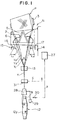
- Figure 4 is a plan view of the main part of Figure 3.
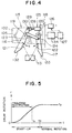
- Figure 5 is a drawing showing the change in drum speed for describing the actions of Figure 4.
- Figure 6 is a front view of the main part of an autowinder being a conventional winding device.
- Figures 1 and 2 show a autowinder utilizing the winding method and that device being a first embodiment of the present invention.
- a winding unit 11 of this autowinder is provided with a traverse drum 2 for winding a yarn Y from a spinning bobbin (supply yarn bobbin) 12 while performing suitable traversing and is arranged such that a package P of predetermined shape (cone shape) is formed while removing yarn defects by a slub catcher 13.
- the traverse drum 2 is supported on one side on the frame 14 of the winding unit 11 and makes the package P rotate by friction contact by the rotation of a drum motor (not shown in the drawings).
- a groove 5 for traversing the yarn Y at a predetermined width A is formed in the peripheral surface of the traverse drum 2 and a cover 6 is arranged in front of that for preventing the yarn Y from flying out of the groove 5.
- a yarn restriction member 15 is arranged below (upstream in the yarn running direction) the traverse drum 2.
- the yarn restriction member 15 comprises a pair of lever plates 16, 17 which are able to swivel freely arranged along the axial direction of the traverse drum 2.
- a drive system 18 for driving these lever plates 16, 17 at predetermined timings is provided.
- the lever plates 16, 17 are supported via vertical shafts 19, 20 on a support bracket (not shown in the drawings) mounted on the frame 14 and the side where the tip swivels extends more forward than the traverse drum 2.
- Indented contact parts 21, 22 are formed on the inside edge of those extending parts in order to suitably contact with the yarn Y.
- the contact parts 21, 22 which contact with the yarn Y form the yarn restriction member 15 being essentially the present invention.
- a link lever 23 spans from the near basal end of the vertical shaft 19 of one lever plate 16 positioned at the small diameter side of the package P to near the tip end of the vertical shaft 20 of the other lever plate 17 positioned at the large diameter side and is supported so as to be able to rotate on both ends by a pin 24.
- the swivelling of one lever plate 16 is transmitted to the other lever plate 17 and the lever tips separate or close together.
- angled surfaces 32, 33 being a shape consisting of two converging lines separated at the top when viewed from above are arranged on the lever plates 16, 17 more toward the tip than the contact parts 21, 22 and are able to contact with the yarn (the end of the yarn which has begun to fly up) further in front of the yarn path during normal winding.
- the drive system 18 comprises an air cylinder 25 connected to one lever plate 16, an electromagnetic valve 26 for supplying or expelling the air for operation of the air cylinder 25, and a controller 27 for suitably operating the electromagnetic valve 26.
- the air cylinder 25 is arranged in the axial direction of the traverse drum 2 and is coupled to the basal end of one lever plate 16 via a vertical pin 30 of a linking tool 29. In short, the air cylinder 25 extends when air is supplied and causes the pair of lever plates 16, 17 to swivel towards each other.
- the projection distance of the contact part 21 of one lever plate 16 is arranged to be greater than the projection distance of the contact part 22 of the other lever plate 17.
- the traverse restriction amount L 1 (the distance the contact part 21 projects into the traverse range A) of the small diameter side is 35mm
- the traverse restriction amount L 2 (the distance the contact part 22 projects into the traverse range A) of the large diameter side is 30mm.
- the traverse restriction amount L 1 of the package small diameter side of the yarn restriction member 15 is larger than the traverse restriction amount L 2 of the package large diameter side of the yarn restriction member 15 (L 1 >L 2 ). This is a countermeasure as end missing tends to more easily occur on the small diameter side as the peripheral surface of the cone shaped package P is in a downwards slanting state toward the small diameter side.
- the operations of the electromagnetic valve 26 can be executed first and a position approximately 50cm from the slub detection place can be cut even at a yarn speed of 1,300m/min and accordingly, this does not present any hindrances to removal of the yarn defect.
- the package P is separated from the drum 2 by a no-yarn detection signal from the slub catcher 13.
- a balloon controller 28 shown in Figure 1 In order to perform operations when the supply yarn 12y runs out, operations of a balloon controller 28 shown in Figure 1 are used.
- the balloon controller 28 restricts the balloon whenever there is unwinding of the spinning bobbin 12 and if the supply yarn 12y of the spinning bobbin 12 becomes scarce, the balloon length is prevented from becoming too long by moving downwards.
- a gate feeler 31 is also used for controlling.
- the gate feeler 31 determines whether to carry out a bobbin exchange by detection of whether there is a lower yarn (supply yarn) or not when there is a yarn breakage or when the yarn is cut. An absence of yarn is detected by the gate feeler 31 at almost the same time as when unwinding of the supply bobbin 12 is complete. Accordingly, by inputting this no-yarn signal c in the controller 27, yarn restriction may be performed by swivelling of the lever plates 16, 17 immediately before flying of the yarn end.
- the upper yarn (package P yarn) is easily picked up by the yarn picking means (suction mouth) when yarn piecing occurs and the success rate of auto-yarn piecing can be improved.
- lever plates 16, 17 and that drive system 18 shown in the present embodiment can be simply arranged a a pre-installed auto-winder due to their simple structure and snow extremely high utility.
- traverse restriction may be performed even when the yarn naturally breaks.
- knotting is performed but maintaining the traverse restriction by the lever plates 16, 17 during this knotting and gradually opening while increasing the rotation of the traverse drum 2 and then removal of the restriction, is also possible.
- the tension can be increased during the period of tension instability when winding starts after knotting and mis-traversing where the yarn Y separates from the groove 5 of the traverse drum 2 can be prevented. Loose winding by a decrease in tension can also be prevented.
- this scramble can be prevented if a traverse restriction is performed, for example, for 6-7 seconds from the start of rotation of the 10 second slow start period.
- the present invention is able to improve package quality as traverse restriction is performed when the yarn tension decreases to a level which affects the quality of the package P.
- a pair of lever plates 16, 17 are shown as a yarn restriction member 15 but if able to restrict the yarn path to the center, any construction is suitable.
- the drive system 18 is not limited to the air cylinder 25 but may be any such construction that operates the yarn restriction member 15 by a predetermined timing.
- Figures 3 and 4 show an autowinder utilizing the winding method and that device being a second embodiment of the present invention.
- a winding unit 111 of this autowinder is provided with a traverse drum 102 for winding a yarn Y from a spinning bobbin (supply yarn bobbin) 112 while performing suitable traversing and is arranged such that a package P of predetermined shape (cone shape) is formed while removing yarn defects by a slub catcher 113.
- the traverse drum 102 is supported on one side on the frame 114 of the winding unit 111 and makes the package P rotate by friction contact by the rotation of a drum motor 134.
- a grave 105 for traversing the yarn Y at a predetermined width A is formed in the peripheral surface of the traverse drum 102 and a cover 106 is arranged in front of that for preventing the yarn Y from flying out of the groove 105.
- a yarn restriction member 15 is arranged below (upstream in the yarn running direction) the traverse drum 102.
- the yarn restriction member 115 comprises a pair of lever members being lever plates 116, 117 which are able to swivel freely arranged along the axial direction of the traverse drum 102.
- a drive system 118 for driving these lever plates 116, 117 at predetermined timings is provided.
- the lever plates 116, 117 are supported via vertical shafts 119, 120 on a support bracket (not shown in the drawings) mounted on the frame 114 and the side where the tip swivels extends more forward than the traverse drum 102.
- Indented contact parts 121, 122 are formed on the inside edge of those extending parts in order to suitable contact with the yarn Y.
- the contact parts 121, 122 which contact the yarn Y form the yarn restriction member 115 being essentially the present invention.
- a link lever 123 spans from near the basal end of the vertical shaft 119 of one lever plate 116 positioned at the small diameter side of the package P to near the tip end of the vertical shaft 120 of the other lever plate 117 positioned at the large diameter side and is supported so as to be freely rotatable on both ends by a pin 124. In short, the swivelling of one lever plate 116 is transmitted to the other lever plate 117 and the lever tips separate or close together.
- angled surfaces 132, 133 being a shape consisting of converging line with the ends top end separated when viewed from above are arranged on the lever plates 116, 117 more toward the tip than the contact part 121, 122 and are able to contact with the yarn (the end of the yarn which has begun to fly up) further infront of the yarn path during normal winding.
- the drive system 118 comprises an air cylinder 125 connected to one lever plate 116, an electromagnetic valve 126 for supplying and expelling the air for operation of the air cylinder 125, and a controller 127 for suitably operating the electromagnetic valve 126.
- the air cylinder 125 is arranged in the axial direction of the traverse drum 102 and is coupled to the basal end of one lever plate 116 via a vertical pin 130 of a linking tool 129. In short, the air cylinder 125 extends when air is supplied and causes the pair of lever plates 116, 117 to swivel towards each other.
- traverse restriction may be performed continuously from knotting up to and after when the drum starts by swivelling of the lever plates 116, 117 during knotting (being when the spinning bobbin yarn and packs yarn are joined including yarn piecing by air).
- the yarn picking means suction mouth
- the yarn picking means easily picks the upper yarn (package P yarn) during yarn piecing and the auto-yarn piecing success rate improves.
- lever plates 116, 117 and that drive system 118 shown in the present embodiment can be simply arranged on a pre-installed auto-winder due to their simple structure and show extremely high utility.
- this yarn restriction member 115 may also be used to prevent end missing. It is believed that the flying of the yarn Y due to a sudden loss of high tension due to a cut yarn Y is one cause of end missing. Accordingly, not only when winding starts, but also when the yarn is cut by the slub catcher 113 and when supply yarn 112y of the spinning bobbin 112 runs out, traverse restriction is performed. In order to drive the lever plates 116, 117 by this timing, a yarn defect detection signal is input from the slub catcher 113 shown in Figure 4 into the controller 127 and before the cutter provided on the slub catcher 113 operates, the air cylinder 125 operates by switching of the electromagnetic valve 126.
- the operations of the electromagnetic valve 126 can be executed first and a position approximately 50cm from the slub detection place can be cut even at a yarn speed of 1,300m/min and accordingly, this does not present any hindrances to removal of the yarn defect.
- a balloon controller 128 shown in Figure 3 In order to perform operations when the supply yarn 112y runs out, operations of a balloon controller 128 shown in Figure 3 are used.
- the balloon controller 128 restricts the balloon whenever there is unwinding of the spinning bobbin 112 and if the supply yarn 112y of the spinning bobbin 112 becomes scarce, the balloon length is prevented from becoming too long by moving downwards. Accordingly, when the balloon controller 128 has been moved to the lowest position, this is detected by a sensor or the like and when this detection signal enters the controller 127 or after a predetermined time has elapsed after receiving this signal, traverse restriction can be performed immediately before the supply yarn 112y runs out if the lever plates 116, 117 are swivelled.
- a gate feeler 131 may also be used for controlling the prevention of end missing.
- the gate feeler 131 determines whether to carry out a bobbin exchange by detection of whether there is a lower yarn (supply yarn) or not when there is a yarn breakage or when the yarn is cut. An absence of yarn is detected by the gate feeler 131 at almost the same time as when unwinding of the supply bobbin 112 is complete. Accordingly, by inputting this no-yarn signal in the controller 127, yarn restriction may be performed by swivelling of the lever plates 116, 117 before flying of the yarn end.
- the projection distance of the contact part 121 of one lever plate 116 is larger than the other lever plate 117. This is a countermeasure as end missing tends to easily occur on the small diameter side as the peripheral surface of the cone shaped package P is in a downwards slanting state toward the small diameter side.
- a pair of lever plates 116, 117 are shown as a yarn restriction member 115 but if able to restrict the yarn and change the tension, any construction is suitable.
- the drive system 118 is not limited to the air cylinder 125 but may be any such construction that operates the yarn restriction member 115 by a predetermined timing.
- the yarn restriction member is arranged of a pair of lever members pushing the yarn towards the center, the device construction may be simplified and application on a pre-existing auto-winder is possible providing high utility.
Abstract
Description
- The present invention relates to a winding method and that device of an autowinder or the like that winds yarn while traversing the yarn.
- As shown in Figure 6, the winding unit 1 of the autowinder is arranged such that a package P of predetermined shape is formed by winding yarn Y on a take-up tube 3 from a spinning bobbin (not shown in the drawing) arranged on the lower part while traversing is being carried out by a
traverse drum 2. Thetraverse drum 2 is arranged so as to be rotated while supported on one side only on aframe 4 of the winding unit 1. Acover 6 in order to prevent the yarn Y from flying from thegroove 5 is arranged a the front side of thetraverse drum 2 and a guide member 7 for restricting the running of the yarn Y corresponding to the traverse width is arranged in front of that. - Further, a
slub catcher 8 that detects yarn defects (slub) in the yarn Y and cuts the yarn is arranged upstream in the yarn running direction from the guide member 7. Apart from these, a knotter for joining the yarn Y when a yarn breakage or yarn cutting by theslub catcher 8 occurs, a tension device for applying a suitable tension to the yarn Y and a suction mouth and suction pipe for transferring the upper yarn and lower yarn to the knotter by rotating during yarn piecing and the like are arranged on the winding unit 1. - However, when performing winding of the yarn Y by this kind of the autowinder, the yarn Y sometimes becomes separated from the package P (end missing) and yarn bundles on the outer layer of the package P sometimes slips to the small diameter side (scramble) resulting in a defective package. For example, in the case of end missing, one cause is the unrestricted flying of the yarn due to the sudden decrease in tension when the yarn breaks or when the supply yarn runs out due to the lastly wound part of the spinning bobbin. In the case of scramble, one cause is the instability of the yarn Y tension when winding starts after yarn piecing.
- The generation of these kinds of defective packages could not be prevented by the
conventional covers 6 and guide members 7. In short, the problem is the prevention of the generation of defective packages by tension decreases and an increase in the package quality. - It is an aim of the present invention to propose a winding method that winds yarn while performing suitable traversing where traverse restrictions are carried out when the yarn tension is in a decreased state. It is preferable to perform traverse restrictions when the yarn tension is in a decreased state, in short, when the yarn is cut, when the supply yarn has run out, when winding starts and the like.
- It is a further aim of the present invention to propose a winding device that winds yarn while performing suitable traversing arranged with a yarn restriction member that restricts the yarn path (traverse width) by moving into the traverse range. It is preferable for there to be a drive system provided for projection of the yarn restriction member into the traverse range immediately before the yarn is cut. It is further preferable for there to be a drive system provided for projection of the yarn restriction member into the traverse range immediately before the supply yarn runs out.
- It is yet further preferable for there to be a drive system for driving the yarn restriction member when the package starts rotating when winding starts. Due to this system, the generation of defective packages by tension decreases can be prevented. The yarn restriction member may be comprised of a pair of lever members or the like that move the yarn towards the center.
- Figure 1 is front view showing a first embodiment of the present invention.
- Figure 2 is a plan view of the main part of Figure 1.
- Figure 3 is front view showing a second embodiment of the present invention.
- Figure 4 is a plan view of the main part of Figure 3.
- Figure 5 is a drawing showing the change in drum speed for describing the actions of Figure 4.
- Figure 6 is a front view of the main part of an autowinder being a conventional winding device.
- Hereafter, a first embodiment of the present invention will be described in accordance with the attached drawings.
- Figures 1 and 2 show a autowinder utilizing the winding method and that device being a first embodiment of the present invention.
- A winding unit 11 of this autowinder is provided with a
traverse drum 2 for winding a yarn Y from a spinning bobbin (supply yarn bobbin) 12 while performing suitable traversing and is arranged such that a package P of predetermined shape (cone shape) is formed while removing yarn defects by aslub catcher 13. Thetraverse drum 2 is supported on one side on theframe 14 of the winding unit 11 and makes the package P rotate by friction contact by the rotation of a drum motor (not shown in the drawings). - A
groove 5 for traversing the yarn Y at a predetermined width A is formed in the peripheral surface of thetraverse drum 2 and acover 6 is arranged in front of that for preventing the yarn Y from flying out of thegroove 5. Ayarn restriction member 15 is arranged below (upstream in the yarn running direction) thetraverse drum 2. - The
yarn restriction member 15 comprises a pair oflever plates traverse drum 2. Adrive system 18 for driving theselever plates lever plates vertical shafts frame 14 and the side where the tip swivels extends more forward than thetraverse drum 2.Indented contact parts contact parts yarn restriction member 15 being essentially the present invention. - A
link lever 23 spans from the near basal end of thevertical shaft 19 of onelever plate 16 positioned at the small diameter side of the package P to near the tip end of thevertical shaft 20 of theother lever plate 17 positioned at the large diameter side and is supported so as to be able to rotate on both ends by apin 24. In short, the swivelling of onelever plate 16 is transmitted to theother lever plate 17 and the lever tips separate or close together. As shown in Figure 2,angled surfaces lever plates contact parts - The
drive system 18 comprises anair cylinder 25 connected to onelever plate 16, anelectromagnetic valve 26 for supplying or expelling the air for operation of theair cylinder 25, and acontroller 27 for suitably operating theelectromagnetic valve 26. Theair cylinder 25 is arranged in the axial direction of thetraverse drum 2 and is coupled to the basal end of onelever plate 16 via avertical pin 30 of a linkingtool 29. In short, theair cylinder 25 extends when air is supplied and causes the pair oflever plates - As shown in Figure 1, during normal winding, in short, when the yarn Y from the spinning
bobbin 12 is being wound on the package P, thecontact parts lever plates traverse drum 2 by being positioned outside the predetermined traverse range A or in contact with the yarn Y1 of the traverse end. Then, when traverse restriction is necessary, theair cylinder 25 extends, thecontact parts - Further, the projection distance of the
contact part 21 of onelever plate 16 is arranged to be greater than the projection distance of thecontact part 22 of theother lever plate 17. For example, when the traverse restriction amount L1 (the distance thecontact part 21 projects into the traverse range A) of the small diameter side is 35mm, the traverse restriction amount L2 (the distance thecontact part 22 projects into the traverse range A) of the large diameter side is 30mm. In short, the traverse restriction amount L1 of the package small diameter side of theyarn restriction member 15 is larger than the traverse restriction amount L2 of the package large diameter side of the yarn restriction member 15 (L1>L2). This is a countermeasure as end missing tends to more easily occur on the small diameter side as the peripheral surface of the cone shaped package P is in a downwards slanting state toward the small diameter side. - This traverse restriction by the
lever plates slub catcher 13 and when thesupply yarn 12y from the spinningbobbin 12 runs out. In short, when (immediately before) the yarn Y flies up due to a sudden disappearance of the high tension (winding tension) of the yarn Y. In order to drive thelever plates slub catcher 13 into thecontroller 27 as shown in Figure 2 and before the cutter provided on theslub catcher 13 operates, input of the yarn defect signal a immediately switches theelectromagnetic valve 26 and operates theair cylinder 25. - It should be noted that if the cutter ON signal of the
slub catcher 13 is delayed so as to be preceded by the yarn defect detection signal a by for example 20msec, the operations of theelectromagnetic valve 26 can be executed first and a position approximately 50cm from the slub detection place can be cut even at a yarn speed of 1,300m/min and accordingly, this does not present any hindrances to removal of the yarn defect. - It should be noted that the package P is separated from the
drum 2 by a no-yarn detection signal from theslub catcher 13. - In order to perform operations when the
supply yarn 12y runs out, operations of aballoon controller 28 shown in Figure 1 are used. Theballoon controller 28 restricts the balloon whenever there is unwinding of the spinningbobbin 12 and if thesupply yarn 12y of the spinningbobbin 12 becomes scarce, the balloon length is prevented from becoming too long by moving downwards. - Accordingly, when the
balloon controller 28 has been moved to the lowest position (shown by the double dotted line B in the drawing) by theactuator 29, this is detected by aposition sensor 30 or the like and when this detection signal b enters thecontroller 27 or after a predetermined time has elapsed after receiving this signal, traverse restriction can be performed immediately before thesupply yarn 12y runs out by swivelling of thelever plates - A
gate feeler 31 is also used for controlling. Thegate feeler 31 determines whether to carry out a bobbin exchange by detection of whether there is a lower yarn (supply yarn) or not when there is a yarn breakage or when the yarn is cut. An absence of yarn is detected by thegate feeler 31 at almost the same time as when unwinding of thesupply bobbin 12 is complete. Accordingly, by inputting this no-yarn signal c in thecontroller 27, yarn restriction may be performed by swivelling of thelever plates - In this way, as a movable
yarn restriction member 15 that moves from outside of the traverse range A to inside of the traverse range A is provided, end missing can be prevented by moving the yarn path more towards the center when there is a sudden decrease in the yarn winding tension. - Furthermore, as the yarn path is restricted to the center by moving the
yarn restriction member 15 inside the traverse range A due to thedrive system 18 before theslub catcher 13 cuts the yarn Y, end missing due to the yarn Y flying when a yarn defect is detected and the yarn Y is cut can be prevented without theyarn restriction member 15 damaging the yarn Y during normal yarn winding. In short, even if the yarn Y flies, that yarn Y does not become a cause of a defective package by it being wound on the package P and moreover, theyarn restriction member 15 dues not exert any detrimental effects on the yarn Y during normal winding thus the quality of the package P is improved. - As the
lever plates bobbin 12 is complete, end missing when the yarn Y flies up due to the no-tension state when the supply yarn has run out can be prevented. In this case also, as the traverse restriction is carried out immediately before the supply yarn runs out, there is no damage to the yarn Y. - Furthermore, as the
lever plates - Yet further still, as the yarn end is moved towards the center of the package P by the
yarn restriction member 15, the upper yarn (package P yarn) is easily picked up by the yarn picking means (suction mouth) when yarn piecing occurs and the success rate of auto-yarn piecing can be improved. - Further, the
lever plates drive system 18 shown in the present embodiment can be simply arranged a a pre-installed auto-winder due to their simple structure and snow extremely high utility. - It should be noted that traverse restriction may be performed even when the yarn naturally breaks.
- Furthermore, After the yarn Y has been cut and the yarn defect removed or after bobbin exchange, knotting is performed but maintaining the traverse restriction by the
lever plates traverse drum 2 and then removal of the restriction, is also possible. In this way, the tension can be increased during the period of tension instability when winding starts after knotting and mis-traversing where the yarn Y separates from thegroove 5 of thetraverse drum 2 can be prevented. Loose winding by a decrease in tension can also be prevented. - Furthermore, during this period of tension instability, as a phenomenon whereby the yarn of the package surface layer moves to the small diameter side in bundle shape (scramble) occurs, this scramble can be prevented if a traverse restriction is performed, for example, for 6-7 seconds from the start of rotation of the 10 second slow start period.
- In summary, the present invention is able to improve package quality as traverse restriction is performed when the yarn tension decreases to a level which affects the quality of the package P.
- Furthermore, in the present embodiment, a pair of
lever plates yarn restriction member 15 but if able to restrict the yarn path to the center, any construction is suitable. Also, thedrive system 18 is not limited to theair cylinder 25 but may be any such construction that operates theyarn restriction member 15 by a predetermined timing. - Hereafter, a second embodiment of the present invention will be described in accordance with the attached drawings.
- Figures 3 and 4 show an autowinder utilizing the winding method and that device being a second embodiment of the present invention.
- A winding unit 111 of this autowinder is provided with a
traverse drum 102 for winding a yarn Y from a spinning bobbin (supply yarn bobbin) 112 while performing suitable traversing and is arranged such that a package P of predetermined shape (cone shape) is formed while removing yarn defects by aslub catcher 113. Thetraverse drum 102 is supported on one side on theframe 114 of the winding unit 111 and makes the package P rotate by friction contact by the rotation of adrum motor 134. A grave 105 for traversing the yarn Y at a predetermined width A is formed in the peripheral surface of thetraverse drum 102 and a cover 106 is arranged in front of that for preventing the yarn Y from flying out of thegroove 105. Ayarn restriction member 15 is arranged below (upstream in the yarn running direction) thetraverse drum 102. - The
yarn restriction member 115 comprises a pair of lever members beinglever plates traverse drum 102. Adrive system 118 for driving theselever plates lever plates vertical shafts frame 114 and the side where the tip swivels extends more forward than thetraverse drum 102.Indented contact parts contact parts yarn restriction member 115 being essentially the present invention. - A
link lever 123 spans from near the basal end of thevertical shaft 119 of onelever plate 116 positioned at the small diameter side of the package P to near the tip end of thevertical shaft 120 of theother lever plate 117 positioned at the large diameter side and is supported so as to be freely rotatable on both ends by apin 124. In short, the swivelling of onelever plate 116 is transmitted to theother lever plate 117 and the lever tips separate or close together. - As shown in Figure 4, angled surfaces 132, 133 being a shape consisting of converging line with the ends top end separated when viewed from above are arranged on the
lever plates contact part - The
drive system 118 comprises anair cylinder 125 connected to onelever plate 116, anelectromagnetic valve 126 for supplying and expelling the air for operation of theair cylinder 125, and acontroller 127 for suitably operating theelectromagnetic valve 126. Theair cylinder 125 is arranged in the axial direction of thetraverse drum 102 and is coupled to the basal end of onelever plate 116 via a vertical pin 130 of alinking tool 129. In short, theair cylinder 125 extends when air is supplied and causes the pair oflever plates - As shown in Figure 3, during normal winding, in short, when yarn Y from the spinning
bobbin 112 is being wound on the package P, thecontact parts lever plates traverse drum 102 by being positioned outside the predetermined traverse range A or in contact with the yarn Y1 of the traverse end. Then, when traverse restriction is necessary, theair cylinder 125 extends, thecontact parts - This traverse restriction by the
lever plates tube 103 occurs or when winding restarts after knotting has finished, in order to prevent slippage between thetraverse drum 102 and take-uptube 103, slow starting is performed in a time period t0 of the first, for example, 10 seconds of the start until the drum speed reaches normal rotation speed r0. However, it is believed that the winding tension of the yarn at this first stage is low and unstable. Consequently, in the time period of, for example, around 6-7 seconds being t1 from the drum start time, the tension is increased by moving the yarn Y towards the center by operation of theyarn restriction member 115 by thecontroller 127 entered with a start signal of thedrum motor 134 sending an operation signal to theelectromagnetic valve 126, thus suitable winding at a predetermined tension is possible. After this predetermined start-up time t1 has elapsed, thelever plates - In this way, as a movable
yarn restriction member 115 which is able to freely move into the traverse range A from outside of the traverse range A is provided and it is projected into the traverse range A by thatdrive system 118 at the start of winding, the tension can be increased to a suitable degree by moving the yarn Y in the lateral direction (towards the center) and mistraversing, loose winding and scramble can be prevented. In short, the generation of defective packages can be prevented and the package P quality is improved. - Furthermore, as the
yarn restriction member 115 is driven during the rotation start-up period at the start of winding, the production of defective packages due to the tension being low and unstable during a slow start can be prevented. It should be noted that traverse restriction may be performed continuously from knotting up to and after when the drum starts by swivelling of thelever plates - Further, the
lever plates drive system 118 shown in the present embodiment can be simply arranged on a pre-installed auto-winder due to their simple structure and show extremely high utility. - Furthermore, this
yarn restriction member 115 may also be used to prevent end missing. It is believed that the flying of the yarn Y due to a sudden loss of high tension due to a cut yarn Y is one cause of end missing. Accordingly, not only when winding starts, but also when the yarn is cut by theslub catcher 113 and whensupply yarn 112y of the spinningbobbin 112 runs out, traverse restriction is performed. In order to drive thelever plates slub catcher 113 shown in Figure 4 into thecontroller 127 and before the cutter provided on theslub catcher 113 operates, theair cylinder 125 operates by switching of theelectromagnetic valve 126. - It should be noted that if the cutter ON signal of the
slub catcher 113 is delayed so as to be preceded by the yarn defect detection signal by for example 20msec, the operations of theelectromagnetic valve 126 can be executed first and a position approximately 50cm from the slub detection place can be cut even at a yarn speed of 1,300m/min and accordingly, this does not present any hindrances to removal of the yarn defect. - In order to perform operations when the
supply yarn 112y runs out, operations of aballoon controller 128 shown in Figure 3 are used. Theballoon controller 128 restricts the balloon whenever there is unwinding of the spinningbobbin 112 and if thesupply yarn 112y of the spinningbobbin 112 becomes scarce, the balloon length is prevented from becoming too long by moving downwards. Accordingly, when theballoon controller 128 has been moved to the lowest position, this is detected by a sensor or the like and when this detection signal enters thecontroller 127 or after a predetermined time has elapsed after receiving this signal, traverse restriction can be performed immediately before thesupply yarn 112y runs out if thelever plates - A
gate feeler 131 may also be used for controlling the prevention of end missing. Thegate feeler 131 determines whether to carry out a bobbin exchange by detection of whether there is a lower yarn (supply yarn) or not when there is a yarn breakage or when the yarn is cut. An absence of yarn is detected by thegate feeler 131 at almost the same time as when unwinding of thesupply bobbin 112 is complete. Accordingly, by inputting this no-yarn signal in thecontroller 127, yarn restriction may be performed by swivelling of thelever plates - It should be noted that, in order to prevent this kind of end missing, projection further towards the center than the yarn path Y3 set as the position where end missing easily occurs is preferable.
- Furthermore, it is preferable for the projection distance of the
contact part 121 of onelever plate 116 to be larger than theother lever plate 117. This is a countermeasure as end missing tends to easily occur on the small diameter side as the peripheral surface of the cone shaped package P is in a downwards slanting state toward the small diameter side. - In the present embodiment, a pair of
lever plates yarn restriction member 115 but if able to restrict the yarn and change the tension, any construction is suitable. Also, thedrive system 118 is not limited to theair cylinder 125 but may be any such construction that operates theyarn restriction member 115 by a predetermined timing. - Accordingly, by the above described embodiment, as traverse restriction is performed when the yarn tension decreases as for example, when the yarn breaks, when the supply yarn runs out or when winding starts, the production of defective packages due to a decrease in the yarn winding tension can be prevented and the package quality can be improved.
- Furthermore, there are no detrimental effects on the yarn during normal winding. If the yarn is cut after performing yarn restriction, the trversing of the cut yarn can be reliably performed. When winding a cone shaped package, if the traverse restriction amount of the small diameter side is greater than the traverse restriction amount of the large diameter side, end missing may be reliably prevented. If traverse restriction is performed by driving the yarn restriction member during the rotation start-up at the start of winding, production of defective packages when the tension is low and unstable during the slow start period may be prevented. If the yarn restriction member is arranged of a pair of lever members pushing the yarn towards the center, the device construction may be simplified and application on a pre-existing auto-winder is possible providing high utility.
Claims (13)
- A winding method that winds yarn while traversing, wheretraverse restriction is performed when the yarn tension is in a decreased state.
- A winding method as in claim 1, wherein traverse restriction is performed immediately before the winding yarn is cut.
- A winding method as in claim 2, wherein, when a defect in the winding yarn is detected, the winding yarn is cut after traverse restriction is performed.
- A winding method as in claim 1, wherein traverse restriction is performed immediately before the supply yarn runs out.
- A winding method as in claim 1, wherein traverse restriction is performed at the start of winding.
- A winding method as in claim 5, wherein traverse restriction is performed when yarn piecing where the yarn of the supply yarn side and yarn of the package side are joined.
- A winding method as in any of claims 1-5, wherein, when winding a cone shaped package, the traverse restriction amount of the small diameter side of the package is larger than the traverse restriction amount of the large diameter side of the package.
- A winding device that winds yarn while traversing, provided witha yarn restriction member that restricts a yarn path by moving from outside of the traverse range to inside the traverse range.
- A winding device as in claim 8, provided with a drive system for projecting the yarn restriction member into the traverse range immediately before the winding yarn is cut.
- A winding device as in claim 8, provided with a drive system for projecting the yarn restriction member into the traverse range immediately before the supply yarn runs out.
- A winding device as in claim 8, provided with a drive system for projecting the yarn restriction member into the traverse range at the start of winding.
- A winding device as in claim 11, wherein the drive system drives the yarn restriction member during the rotation start-up period at the start of winding.
- A winding device as in any of claims 8-12, wherein the yarn restriction member is a pair of lever members that move the yarn towards the center.
Applications Claiming Priority (6)
| Application Number | Priority Date | Filing Date | Title |
|---|---|---|---|
| JP15844096A JP2871599B2 (en) | 1996-06-19 | 1996-06-19 | Winding method and device |
| JP15843996A JP2937125B2 (en) | 1996-06-19 | 1996-06-19 | Winding method and device |
| JP158439/96 | 1996-06-19 | ||
| JP15843996 | 1996-06-19 | ||
| JP158440/96 | 1996-06-19 | ||
| JP15844096 | 1996-06-19 |
Publications (3)
| Publication Number | Publication Date |
|---|---|
| EP0814045A2 true EP0814045A2 (en) | 1997-12-29 |
| EP0814045A3 EP0814045A3 (en) | 1998-12-30 |
| EP0814045B1 EP0814045B1 (en) | 2001-09-05 |
Family
ID=26485547
Family Applications (1)
| Application Number | Title | Priority Date | Filing Date |
|---|---|---|---|
| EP19970108470 Expired - Lifetime EP0814045B1 (en) | 1996-06-19 | 1997-05-26 | Winding method and device |
Country Status (3)
| Country | Link |
|---|---|
| EP (1) | EP0814045B1 (en) |
| CN (1) | CN1184123C (en) |
| DE (1) | DE69706481T2 (en) |
Cited By (5)
| Publication number | Priority date | Publication date | Assignee | Title |
|---|---|---|---|---|
| DE102004052564A1 (en) * | 2004-10-29 | 2006-05-04 | Saurer Gmbh & Co. Kg | Method and device for operating a workstation of a textile machine producing cross-wound bobbins |
| EP2105399A2 (en) | 2008-03-24 | 2009-09-30 | Murata Machinery, Ltd. | Yarn Winding Device and Yarn Winding Method |
| DE102009009971A1 (en) | 2009-02-21 | 2010-08-26 | Oerlikon Textile Gmbh & Co. Kg | Method for operating workstation of cross-wound bobbin machine, involves displacing free thread end in direction of bobbin edge and positioning free thread end with defined length outside of bobbin edge |
| DE102012002986A1 (en) | 2012-02-15 | 2013-08-22 | Oerlikon Textile Gmbh & Co. Kg | Textile machine i.e. cross reeling machine, has shielding cover partly covering holder plate of frame and comprising thread separation cutters for cutting thread ends provided beside lateral surface of coil after reeling interruption |
| EP3640173A4 (en) * | 2017-06-15 | 2021-03-10 | Murata Machinery, Ltd. | Yarn-winding device |
Families Citing this family (5)
| Publication number | Priority date | Publication date | Assignee | Title |
|---|---|---|---|---|
| KR20050123449A (en) * | 2004-06-25 | 2005-12-29 | 최영호 | Apparatus for winding yarn |
| JP2009046268A (en) * | 2007-08-21 | 2009-03-05 | Murata Mach Ltd | Automatic winder |
| DE102018125622A1 (en) * | 2018-10-16 | 2020-04-16 | Saurer Spinning Solutions Gmbh & Co. Kg | Method of operating a winding device |
| DE102022102407A1 (en) | 2022-02-02 | 2023-08-03 | Saurer Spinning Solutions Gmbh & Co. Kg | Thread guiding device for a work station of a textile machine producing cross-wound bobbins |
| DE102022001139A1 (en) | 2022-04-01 | 2023-10-05 | Oerlikon Textile Gmbh & Co. Kg | Winding device for winding up a spinning thread and method for winding up a spinning thread |
Citations (5)
| Publication number | Priority date | Publication date | Assignee | Title |
|---|---|---|---|---|
| DE646625C (en) * | 1935-08-24 | 1937-06-18 | Carl Zangs Akt Ges Maschf | Cross-winding machine with a grooved roller for the thread guide |
| DE1946220A1 (en) * | 1969-09-12 | 1971-03-25 | Henrich Kg | Winding device for wires, strands, ropes or the like. |
| JPS63306166A (en) * | 1987-06-09 | 1988-12-14 | Teijin Seiki Co Ltd | Wind-up device for yarn |
| EP0510829A1 (en) * | 1991-04-25 | 1992-10-28 | Rieter-Scragg Limited | Winding apparatus |
| DE4220188A1 (en) * | 1991-06-19 | 1992-12-24 | Murata Machinery Ltd | WINDING METHOD AND DEVICE |
-
1997
- 1997-03-26 CN CN 97103718 patent/CN1184123C/en not_active Expired - Lifetime
- 1997-05-26 EP EP19970108470 patent/EP0814045B1/en not_active Expired - Lifetime
- 1997-05-26 DE DE1997606481 patent/DE69706481T2/en not_active Expired - Fee Related
Patent Citations (5)
| Publication number | Priority date | Publication date | Assignee | Title |
|---|---|---|---|---|
| DE646625C (en) * | 1935-08-24 | 1937-06-18 | Carl Zangs Akt Ges Maschf | Cross-winding machine with a grooved roller for the thread guide |
| DE1946220A1 (en) * | 1969-09-12 | 1971-03-25 | Henrich Kg | Winding device for wires, strands, ropes or the like. |
| JPS63306166A (en) * | 1987-06-09 | 1988-12-14 | Teijin Seiki Co Ltd | Wind-up device for yarn |
| EP0510829A1 (en) * | 1991-04-25 | 1992-10-28 | Rieter-Scragg Limited | Winding apparatus |
| DE4220188A1 (en) * | 1991-06-19 | 1992-12-24 | Murata Machinery Ltd | WINDING METHOD AND DEVICE |
Non-Patent Citations (1)
| Title |
|---|
| PATENT ABSTRACTS OF JAPAN vol. 013, no. 143 (M-811), 7 April 1989 & JP 63 306166 A (TEIJIN SEIKI CO LTD), 14 December 1988 * |
Cited By (10)
| Publication number | Priority date | Publication date | Assignee | Title |
|---|---|---|---|---|
| DE102004052564A1 (en) * | 2004-10-29 | 2006-05-04 | Saurer Gmbh & Co. Kg | Method and device for operating a workstation of a textile machine producing cross-wound bobbins |
| WO2006048106A1 (en) * | 2004-10-29 | 2006-05-11 | Saurer Gmbh & Co. Kg | Method and device for operating a work station of a textile machine that produces cross-wound bobbins |
| EP2105399A2 (en) | 2008-03-24 | 2009-09-30 | Murata Machinery, Ltd. | Yarn Winding Device and Yarn Winding Method |
| EP2105399A3 (en) * | 2008-03-24 | 2010-10-06 | Murata Machinery, Ltd. | Yarn Winding Device and Yarn Winding Method |
| DE102009009971A1 (en) | 2009-02-21 | 2010-08-26 | Oerlikon Textile Gmbh & Co. Kg | Method for operating workstation of cross-wound bobbin machine, involves displacing free thread end in direction of bobbin edge and positioning free thread end with defined length outside of bobbin edge |
| CN101837909A (en) * | 2009-02-21 | 2010-09-22 | 欧瑞康纺织有限及两合公司 | The method and apparatus of the station of the weaving loom of operation manufacturing cross winding bobbin and the station of carrying out this method |
| CN101837909B (en) * | 2009-02-21 | 2013-01-23 | 欧瑞康纺织有限及两合公司 | Method and device for operating station of textile machine for manufacturing cross-wound spools and station for executing the method |
| DE102009009971B4 (en) * | 2009-02-21 | 2017-03-16 | Saurer Germany Gmbh & Co. Kg | Method and apparatus for operating a workstation of a textile machine producing cross-cheeses, and workstation for carrying out the method |
| DE102012002986A1 (en) | 2012-02-15 | 2013-08-22 | Oerlikon Textile Gmbh & Co. Kg | Textile machine i.e. cross reeling machine, has shielding cover partly covering holder plate of frame and comprising thread separation cutters for cutting thread ends provided beside lateral surface of coil after reeling interruption |
| EP3640173A4 (en) * | 2017-06-15 | 2021-03-10 | Murata Machinery, Ltd. | Yarn-winding device |
Also Published As
| Publication number | Publication date |
|---|---|
| DE69706481T2 (en) | 2002-06-13 |
| CN1168856A (en) | 1997-12-31 |
| DE69706481D1 (en) | 2001-10-11 |
| EP0814045A3 (en) | 1998-12-30 |
| CN1184123C (en) | 2005-01-12 |
| EP0814045B1 (en) | 2001-09-05 |
Similar Documents
| Publication | Publication Date | Title |
|---|---|---|
| US4083171A (en) | Method and apparatus for eliminating an abnormality in a thread to be wound onto the bobbin of an open-end spinning device | |
| US5016829A (en) | Takeup machine | |
| EP2594517B1 (en) | Yarn winding device | |
| CN101759062B (en) | Yarn winding device and automatic winder | |
| EP1857394B1 (en) | Method for pulling out a yarn end from a winding package | |
| WO2012008101A1 (en) | Bobbin winding device | |
| EP0814045B1 (en) | Winding method and device | |
| EP2075358A2 (en) | Spinning machine | |
| GB2100300A (en) | Method and device for winding a newly joined thread onto a tube newly inserted into a winding device | |
| JP2011037608A (en) | Textile machinery | |
| EP0847952B1 (en) | Take-up winder for an elastic yarn | |
| US5490375A (en) | Method of respinning using ancillary yarn | |
| EP0787674B1 (en) | Unnecessary yarn removal method and device for a winding package | |
| JP3646682B2 (en) | Method of attaching yarn to winding tube in automatic winder and automatic winder | |
| JP4082250B2 (en) | Thread loosening device for spinning machine | |
| JP3888318B2 (en) | Spinning machine | |
| JP3707413B2 (en) | Yarn winder with thread thickness detector | |
| JP4019984B2 (en) | Spinning machine | |
| JPH0342468A (en) | Thread end drop preventing method | |
| JP2010275099A (en) | Traverse drum and yarn winding device equipped therewith | |
| JP3888320B2 (en) | Spinning machine | |
| JP2871599B2 (en) | Winding method and device | |
| JP2023054863A (en) | Yarn winder | |
| EP1035058A2 (en) | Device for forming a start bunch in an automatic winder | |
| JP2005231823A (en) | Yarn winding machine |
Legal Events
| Date | Code | Title | Description |
|---|---|---|---|
| PUAI | Public reference made under article 153(3) epc to a published international application that has entered the european phase |
Free format text: ORIGINAL CODE: 0009012 |
|
| AK | Designated contracting states |
Kind code of ref document: A2 Designated state(s): DE IT |
|
| PUAL | Search report despatched |
Free format text: ORIGINAL CODE: 0009013 |
|
| AK | Designated contracting states |
Kind code of ref document: A3 Designated state(s): DE IT |
|
| 17P | Request for examination filed |
Effective date: 19990303 |
|
| 17Q | First examination report despatched |
Effective date: 19990607 |
|
| GRAG | Despatch of communication of intention to grant |
Free format text: ORIGINAL CODE: EPIDOS AGRA |
|
| GRAG | Despatch of communication of intention to grant |
Free format text: ORIGINAL CODE: EPIDOS AGRA |
|
| GRAH | Despatch of communication of intention to grant a patent |
Free format text: ORIGINAL CODE: EPIDOS IGRA |
|
| GRAH | Despatch of communication of intention to grant a patent |
Free format text: ORIGINAL CODE: EPIDOS IGRA |
|
| GRAA | (expected) grant |
Free format text: ORIGINAL CODE: 0009210 |
|
| AK | Designated contracting states |
Kind code of ref document: B1 Designated state(s): DE IT |
|
| REF | Corresponds to: |
Ref document number: 69706481 Country of ref document: DE Date of ref document: 20011011 |
|
| PLBE | No opposition filed within time limit |
Free format text: ORIGINAL CODE: 0009261 |
|
| STAA | Information on the status of an ep patent application or granted ep patent |
Free format text: STATUS: NO OPPOSITION FILED WITHIN TIME LIMIT |
|
| 26N | No opposition filed | ||
| PGFP | Annual fee paid to national office [announced via postgrant information from national office to epo] |
Ref country code: DE Payment date: 20080523 Year of fee payment: 12 |
|
| PGFP | Annual fee paid to national office [announced via postgrant information from national office to epo] |
Ref country code: IT Payment date: 20080524 Year of fee payment: 12 |
|
| PG25 | Lapsed in a contracting state [announced via postgrant information from national office to epo] |
Ref country code: DE Free format text: LAPSE BECAUSE OF NON-PAYMENT OF DUE FEES Effective date: 20091201 |
|
| PG25 | Lapsed in a contracting state [announced via postgrant information from national office to epo] |
Ref country code: IT Free format text: LAPSE BECAUSE OF NON-PAYMENT OF DUE FEES Effective date: 20090526 |