JP4019984B2 - Spinning machine - Google Patents

Spinning machine Download PDF

Info

Publication number
JP4019984B2
JP4019984B2 JP2003072675A JP2003072675A JP4019984B2 JP 4019984 B2 JP4019984 B2 JP 4019984B2 JP 2003072675 A JP2003072675 A JP 2003072675A JP 2003072675 A JP2003072675 A JP 2003072675A JP 4019984 B2 JP4019984 B2 JP 4019984B2
Authority
JP
Japan
Prior art keywords
yarn
spinning
slack eliminating
roller
tension
Prior art date
Legal status (The legal status is an assumption and is not a legal conclusion. Google has not performed a legal analysis and makes no representation as to the accuracy of the status listed.)
Expired - Fee Related
Application number
JP2003072675A
Other languages
Japanese (ja)
Other versions
JP2004277943A (en
Inventor
修 平尾
昌澄 重山
宏幸 八木
Current Assignee (The listed assignees may be inaccurate. Google has not performed a legal analysis and makes no representation or warranty as to the accuracy of the list.)
Murata Machinery Ltd
Original Assignee
Murata Machinery Ltd
Priority date (The priority date is an assumption and is not a legal conclusion. Google has not performed a legal analysis and makes no representation as to the accuracy of the date listed.)
Filing date
Publication date
Application filed by Murata Machinery Ltd filed Critical Murata Machinery Ltd
Priority to JP2003072675A priority Critical patent/JP4019984B2/en
Priority to EP11182192.2A priority patent/EP2423142B1/en
Priority to EP20040003083 priority patent/EP1457447B1/en
Priority to CNB2004100080498A priority patent/CN100352751C/en
Publication of JP2004277943A publication Critical patent/JP2004277943A/en
Application granted granted Critical
Publication of JP4019984B2 publication Critical patent/JP4019984B2/en
Anticipated expiration legal-status Critical
Expired - Fee Related legal-status Critical Current

Links

Images

Description

【0001】
【発明の属する技術分野】
本発明は、複数の紡績ユニットが配設された紡績機であって、紡績装置から巻取装置までの間に生じる糸の弛みを取る糸弛み取り装置を備えるものに関する。
【0002】
【従来の技術】
スライバ(繊維束)を原料として紡績糸を生成し、所定のパッケージに巻き取る紡績機(例えば空気式紡績機など)にあっては、糸欠陥を検出したならば、糸欠陥箇所をカッターで切断し除去した後、紡績装置から次々に送られてくる糸の先端とパッケージ側の糸端とを、糸継ぎ装置で糸継ぎするようになっている。糸継ぎ作業は糸の巻取を停止した状態で行うから、紡績装置から次々に送給される糸の弛みを取り除くため、例えば特許文献1に記載されるような、スラックチューブと呼ばれる吸引管で余剰の糸を吸引する手段を採用する場合もある。しかるに、近年の紡績速度の高速化による糸弛み量の増大に伴い、前記吸引管方式では増量した糸の弛み取りに対応するのが困難になりつつある。しかも吸引管方式には、負圧による吸引空気のみによる引っ張りのため、糸弛み取り時に糸に十分な張力を与えるのが難しいという問題がある。
【0003】
そこで吸引管方式に代わる手段として、特許文献2に記載されるような、紡績装置から送給される糸を、貯蔵ローラ(弛み取りローラ)に一時的に巻き付けることによって糸弛みを解消するローラ式糸貯蔵装置(糸弛み取り装置)が提案されている。この糸貯蔵装置は、紡績機に沿って走行可能な保守装置(作業台車)に、糸結合装置(糸継ぎ装置)と共に積載されている。また、上記糸貯蔵装置には、貯蔵ローラと共に、糸戻しリングからなる戻し素子が設けられている。この戻し素子は、糸継ぎ時に糸を貯蔵ローラに巻き付かせる際に糸の導入を案内し、パッケージへの巻取再開後、糸を貯蔵ローラから解舒する際には、ある程度の解舒張力を付与しつつ糸を巻取パッケージへ案内する機能を有するものである。
【0004】
【特許文献1】
特開2001−159039号公報
【特許文献2】
特公平4−13272号公報
【0005】
【発明が解決しようとする課題】
特許文献2に記載の技術は、糸貯蔵装置が、保守装置に糸結合装置と共に積載されるものである。このため、紡績機のいずれかの紡績ユニットへ保守装置を移動させて糸継ぎ作業を行っている間に、別の紡績ユニットから糸継ぎ作業の要求が出された場合、糸継ぎ実行中の紡績ユニットにおいて糸継ぎ作業を完了させ、糸の弛みを巻き取っている貯蔵ローラからの糸の解舒が終了しない限り、保守装置は別の紡績ユニットへ移動することができない。それ故、糸継ぎ作業の実行時間が紡績作業の稼働時間に直接影響し、糸継ぎ作業の遅れが紡績作業全体の遅延をもたらすおそれがある、という問題があった。
【0006】
そこで、特許文献2に記載の糸貯蔵装置において、糸継ぎ完了後の貯蔵ローラからの糸解舒速度を速めるために、糸解舒を案内する戻し素子の糸に対する抵抗力を小さくすることが考えられる。しかし、このようにすると、糸解舒時における戻し素子と巻取パッケージとの間の糸張力=巻取張力が、正規の巻取時と比べて非常に低いものとなる。これは即ち、同時に貯蔵ローラから解舒された糸が巻取パッケージに巻き取られる際の巻取張力を低下せしめて、糸解舒時と正規の巻取時との間で巻取張力差を生じさせることとなる。その結果、巻取パッケージの巻取状態が不均一になり、張力の大小の差によりパッケージ端面に段形状が形成されるおそれがあった。
【0007】
【課題を解決するための手段】
本発明は、前記従来技術の問題点を解決できる手段を提供するものであって、その特徴とするところは、複数の紡績ユニットが配設され、糸継ぎ装置を備える作業台車が各紡績ユニット間を移動可能に構成された紡績機において、弛み取りローラと、この弛み取りローラから巻き付いた糸を解舒するにあたり当該糸に所定の解舒張力を付与するための解舒張力付与部材とを有する糸弛み取り装置が、各紡績ユニットごとに設けられ、前記解舒張力付与部材に、弛み取りローラから解舒される糸に付与する解舒張力の大きさを紡績条件に応じて調整することが可能な解舒張力調整機構が設けられ、前記弛み取りローラごとに駆動手段が備えられて、各弛み取りローラをそれぞれ独立に回転駆動できるように構成され、前記糸弛み取り装置は、糸継ぎ作業時には糸継ぎに伴い発生する弛み糸を弛み取りローラに巻き取って、弛み取りローラから解舒される糸の張力を正規の巻取時の糸張力と一致又は接近させるものであり、通常紡績時には弛み取りローラに糸を常時巻き付けて巻取張力差を吸収するものであることである(請求項1)。
【0008】
かかる構成を採用することにより、糸弛み取り装置が各紡績ユニットごとに設けられるので、糸継ぎを必要とする紡績ユニットにおいて糸継ぎ作業を完了させたならば、当該紡績ユニットの糸弛み取り装置で糸解舒を行っている間に、作業台車を別の紡績ユニットへ移動させることが可能となる。従って、複数の紡績ユニットについて糸継ぎ作業を連続して行う場合に、紡績ユニット一つ当たりの作業台車の停止時間を短縮できるから、紡績機の稼働効率が向上する。また、糸弛み取り装置の弛み取りローラから解舒する糸に所定の解舒張力を付与する解舒張力付与部材を有すると共に、弛み取りローラに巻き付かせた糸を解舒するのに時間をかけられるので、解舒中の糸に適正な張力を付与するのが容易である。すなわち、解舒中の糸張力を、正規の巻取時の糸張力と一致又は接近させることができるから、巻取状態の良好な糸パッケージを確実に得ることができる。さらにまた、本発明の糸弛み取り装置は、通常紡績時には糸を常時巻き付けるものとしたので、例えばコーン巻きパッケージを形成する際に、大径側と小径側とで生じる巻取速度の差による巻取張力差を吸収することができる。
【0009】
前記紡績機において、解舒張力付与部材に、弛み取りローラから解舒される糸に付与する解舒張力の大きさを紡績条件に応じて調整することが可能な解舒張力調整機構を設けたので、該解舒張力調整機構により弛み取りローラから解舒するときの糸張力を、糸種・番手等の紡績条件に応じて調整することにより、正規の巻取時の糸張力と一致又は接近させることが可能となる。
【0010】
さらに前記紡績機において、弛み取りローラごとに駆動手段を備え、各弛み取りローラをそれぞれ独立に回転駆動できるように構成したので、紡績ユニットごとに、異なる糸弛み取り作業を独立して行わせることが可能となる。
【0011】
また前記解舒張力付与部材に、弛み取りローラに糸を導入するための糸掛部材としての機能を持たせることが考えられる。この場合は、糸弛み取り装置の部品点数を減らして、構成を簡素化できる利点が得られる(請求項2)。
【0012】
なお前記紡績機において、作業台車を、紡績ユニットから出力される糸継ぎ要求信号に基づいて該当する紡績ユニットの位置へ移動させ、該当紡績ユニット位置に到着すると、到着検知信号に基づき、前記弛み取りローラの回転を開始させるように設定することが考えられる(請求項3)。かかる構成を採用することにより、糸弛み取り装置の弛み取りローラの動作と作業台車の動作との連携を確実に取ることができる。
【0013】
なお、前記弛み取りローラに巻き取られている糸の解舒終了後、前記解舒張力付与部材を、糸と係合することのない位置へ移動させる構成を採用することも考えられる。これにより、糸解舒後に解舒張力付与部材が正規巻取中の糸と接触摩擦するのを防止できるから、巻取再開後、糸品質に悪影響を与えるのを回避することができる。
【0014】
【発明の実施の形態】
以下、本発明に係る紡績機の一実施形態を図面に基づいて説明する。なお、本明細書において「上流・下流」とは、紡績時における糸の走行方向を基準として上流・下流を指し、具体的には、紡績装置側を上流、巻取装置側を下流とする。
【0015】
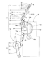
図1は本発明が適用される紡績機1の一例を示す正面図、図2は同紡績機1における一部分の内部構造を概略的に示す拡大図である。例えば空気紡績機等から成る紡績機1は、制御部1A、多数の紡績ユニット2が並設された紡績部1B、ブロアー部1C、及び、糸継ぎ装置を備え紡績ユニット2間をレールRに沿って走行自在になされた作業台車3を主要構成部材としている。
【0016】
制御部1Aは、紡績部1Bを構成する全部の紡績ユニット2に共通して駆動力を与える駆動シャフト41・42・43の駆動用モータ31・32・33、紡績ユニット2ごとに設けられているモータ34・35、及び、巻取装置12等の動作を制御するものである。本実施形態では、入力部aに入力される各種設定値(紡出速度、紡出速度と巻取ローラ速度との比率など)に基づき、演算部bがモータ31〜34に対し、インバータc又はドライバ基板30を介して、紡出速度情報を出力する。また糸弛み取り装置10のモータ35に対し、ドライバ基板40を介して、弛み取りローラ(後述)の回転速度情報を出力するようになされている。
【0017】
紡績部1Bは、多数の紡績ユニット2が並設されたものであって、各紡績ユニット2はそれぞれ独立に制御できるように構成されている。また本発明に係る紡績機1は、紡績装置5及び巻取装置12と共に、糸弛み取り装置10が、紡績ユニット2ごとに備えられている点に特徴を有している。なお、紡績ユニット2の構造の詳細については、後ほど説明する。
【0018】
ブロアー部1Cは、紡績ユニット2に対し、エアーダクトを通じて、所要箇所に負圧(吸引圧)を付与する負圧供給手段を収納するものであって、糸吸引装置7等に負圧を作用させる。
【0019】
作業台車3は、糸継ぎを必要とする任意の紡績ユニット2から発信される糸継ぎ要求信号に基づき、レールR上を走行して該当する紡績ユニット2位置へ移動し停止できるようになっているものであって、紡績部1B部分の構成を概略的に表した側面断面図である図3に示す如く、ノッターやスプライサー等の糸継ぎ装置17、紡績装置5で形成された糸の端部を吸引して糸継ぎ装置17へ導くサクションパイプ18、巻取装置12に支持されたパッケージ16の糸端を吸引して糸継ぎ装置17へ導くサクションマウス19、必要時に糸Yに接触して(図12参照)糸張力を付与するテンションアーム20を備えている。
【0020】
なお、各紡績ユニット2ごとに、糸継ぎ装置17、サクションパイプ18、サクションマウス19を設ける例も考えられるが、紡績ユニット2の並設方向に沿って走行する作業台車3に、糸継ぎ装置17、サクションパイプ18及びサクションマウス19を積載することで、これら一組だけで全部の紡績ユニット2に対する糸継ぎ作業を行うことができるから、紡績機1の構造を簡単にすることができる。
【0021】
前記作業台車3に備えられている糸継ぎ用のサクションパイプ18は、紡績側糸端の吸引部材として機能するものであって、先端に吸引口18aを備えると共に、枢支部18bを中心に回動自在になされている。糸継ぎ作業の際には、図6中に二点鎖線で示す如く上方へ回動して、吸引口18aを紡績装置5の糸排出口付近に位置させ、紡出されてくる糸Yの糸端を吸引したのち、吸引状態のまま同図に実線で示す初期位置まで下方へ回動することにより、紡績側の糸Y1を糸継ぎ装置17へ導く。他方、サクションマウス19は、巻取り側糸端の吸引部材として機能するものであって、先端に吸引口19aを備えると共に、枢支部19bを中心に回動自在に成されている。そして糸継ぎ作業の際には、パッケージ16を回転停止させた後、このパッケージ16を通常とは逆方向に回転させ、糸端を下方へ回動させたサクションマウス19先端の吸引口19aで吸引・捕捉して糸出しを行ったのち、吸引状態のまま同図中に実線で示す初期位置まで上方へ回動することにより、パッケージ16側の糸Y2を糸継ぎ装置17へ導く。
【0022】
次に、前記紡績部1Bに複数配設される紡績ユニット2について説明する。紡績ユニット2は原料の繊維束Sから糸Yを製造する一つの単位であって、図3に示すように、糸道Eの上流側から下流側に沿って順に配置された、ドラフト装置4、紡績装置5、糸送り装置6、糸吸引装置7、カッター8、糸欠陥検出器9、糸弛み取り装置10、ワキシング装置11、巻取装置12から構成されている。
【0023】
ドラフト装置4は、例えば、上流側からバックローラ4a・サードローラ4b・エプロン4cが張設されたセカンドローラ4d・フロントローラ4eからなる4線式のものが適用される。紡績装置5は、例えば、旋回気流を利用して繊維束Sから紡績糸Y(以下、単に「糸Y」と言う。)を生成する空気式のもので、紡出速度が数百m/分の高速紡績が可能なものが採用される。そのほか紡績装置5は、空気紡績ノズルと加撚ローラ対とにより糸Yを生成するものや、ロータ回転により糸Yを生成するオープンエンド紡績機など、他の構造のものに置換することが可能である。糸送り装置6は、ニップローラ6aとデリベリローラ6bとから成り、両ローラ6a,6b間に糸Yを挟持して下流側へ送給するものである。糸吸引装置7は、常時、吸引状態にあり、糸欠陥検出器9が糸Yの欠陥を検出したときにカッター8が切断した糸Yの断片を吸引除去する。
【0024】
巻取装置12は、クレードルアーム14に保持したボビン15に糸Yを巻き付けてパッケージ16を形成するためのものであって、ボビン15又はパッケージ16に接触して回転する回転ドラム13を備えており、クレードルアーム14は、回転ドラム13に対し、ボビン15又はパッケージ16を離接させることができるよう回動可能に構成されている。
【0025】
各紡績ユニット2に設けられる糸弛み取り装置10は、図3乃至5に示すように、弛み糸Yを外周面21a(図17参照)に巻き付け貯留する弛み取りローラ21と、条件に応じて弛み取りローラ21と同期して又は独立に同心回転する解舒張力付与部材22と、弛み取りローラ21のやや上流側に配置される上流側ガイド23と、弛み取りローラ21を回転駆動するステッピングモータ等の駆動手段35と、該駆動手段35を制御するドライバ基板40(図2参照)と、弛み取りローラ21の下流位置に設けられスリット36aを有する下流側ガイド36とを備えており、これらは、ブラケット37などによって紡績ユニット2に固定されている。
【0026】
弛み取りローラ21は、図16〜18に示すように、駆動手段35の駆動軸35aに固着され該駆動軸35aと一体的に回転する。従って、演算部bにより設定される回転速度に忠実に従った弛み取りローラ21の回転制御が可能となっている。また、解舒張力付与部材22を有する側を先端P、駆動手段35に接続される側を基端Qとすると、外周面21aには、基端Q側及び先端P側それぞれに端面へ向かって拡径するテーパ部21b、21dが形成され、これらの中間部は同一径の円筒部21cとなっている。そして糸継ぎ時に、紡績装置5から紡出されてくる糸Yを基端Q側から外周面21aに巻き付け、しかるのち先端P側から巻取装置12側へ向かって解舒するようになされている(図9〜11参照)。基端Q側のテーパ部21bは、供給され巻き付いた糸Yを、大径部分21b−1から小径部分21b−2へ円滑に移動させて中間の円筒部21cへ到達させることにより、糸Yを円筒部21c表面に規則正しく巻き付かせる機能を有する。また先端P側のテーパ部21dは、解舒の際に、巻き付かせた糸Yが一度に抜け出る輪抜け現象を抑止すると同時に、糸Yを小径部分21d−2から大径部分21d−1へ順送りに巻き付け糸層を送り出して、糸Yの円滑な引き出しを確保する機能を有している。
【0027】
弛み取りローラ21の先端P側に設けられる解舒張力付与部材22は、図18に示す如く、フライヤー22aを伝達力調節機構によりローラ21に対し同心回転可能に取り付けて成るものであって、上記伝達力調節機構の構成は次の如くである。すなわち、ローラ21の中央部に突設した軸部21eに、ベアリング等の軸受部材22cを介してホイール部材22bを回転自在に装着し、このホイール部材22bにフライヤー22aの基部を取着する。そして、このホイール部材22bを、上記軸部21e先端のボルト部分に螺合させた例えばナット部材22dや押さえ部材22e等から成る伝達力調整操作部22gで、例えばバネ等の付勢手段から成る伝達力付与部材22fを抜け止めすることにより、取り付けている。従って本実施形態の伝達力調節機構は、軸部21eのボルト部分に螺合する伝達力調整操作部22gの締め付け操作により、伝達力付与部材22fの押圧力(摩擦力)を無段階に調整可能としている。
【0028】
本実施例の伝達力調節機構は、軸部21eに螺合するナット部材22d等の伝達力調整操作部22gの締め付け操作により、伝達力付与部材22fの押圧力(摩擦力)を無段階に調整可能としているが、これに限らず、軸部21eに代えて、長手方向の所定間隔ごとに押さえ部材22eを段階的に位置決めする位置規制部を施した軸部を設け、該軸部に対する押さえ部材22eの装着位置を段階的に変更可能とするものでもよい。また、軸部の長手方向での長さが異なる押さえ部材22eを複数種用意し、軸部に取着する押さえ部材22eを条件によって適宜取り替え可能とするものであってもよい。さらに、これら摩擦式調整機構以外にも、非接触式調節機構として、例えば、電磁石を用いた電磁クラッチ方式とし、磁石の磁気的吸引力を変更することにより、伝達力の大きさを調整し得るものも考えられる。
【0029】
なお本実施形態のように、上記伝達力調節機構を弛み取りローラ21と解舒張力付与部材22との接続部分に設け、伝達力調整操作部22gを、弛み取りローラ21の先端P側に露出させるよう構成することにより、作業者による伝達力調整作業が容易に行える。また伝達力調節機構が、円滑な糸解舒の障害とならないようにするため、弛み取りローラ21から解舒される糸Yの軌跡が形成する面と伝達力調節機構とが干渉しないよう構成することが望ましい。本実施形態では図示するように、軸部21eの先端を、ローラ先端Pよりもローラ21の奥側へ入り込む構造としたので、弛み取りローラ21から解舒される糸Yの糸道に軸部21eや伝達力調整操作部22gが干渉することが全くなく、円滑な糸解舒を妨げるおそれがない。
【0030】
前記伝達力調節機構は、フライヤー22aの弛み取りローラ21に対する回転抵抗の大きさを調節可能にするものである。すなわち、上記押さえ部材22eの締め付け度合いを弱くすれば、ホイール部材22bに対する伝達力付与部材22fの押圧力(あるいは摩擦力)が弱まるようになっており、わずかな負荷を与えるだけでフライヤー22aがスリップし、弛み取りローラ21の回転とは独立に回動することができるようになる。反対に、上記押さえ部材22eの締め付け度合いを強くすれば、ホイール部材22bに対する伝達力付与部材22fの押圧力が強まるようになっており、フライヤー22aは非常に大きな負荷が作用しない限りスリップせず、弛み取りローラ21に従動してと一体に回転する。
【0031】
従って、本実施形態の解舒張力付与部材22は、押さえ部材22eの締め付け度合いを適当に調節することで、弛み取りローラ21とは独立に回転し得るフライヤー22aの挙動を、弛み取りローラ21から解舒される糸Yの張力に関連させて調節することが可能である。すなわち、糸種や番手等の紡績条件によって異なる弛み取りローラ21からの糸Yの解舒張力を、上記伝達力調節機構により予め調節可能である。フライヤー22aの挙動は、伝達力付与部材22fを介して弛み取りローラ21から伝達される回転力と、弛み取りローラ21から解舒する糸Yの張力との相互作用で決まる。逆に言えば、上記伝達力調節機構によりフライヤー22aの挙動をあらかじめ調節しておけば、フライヤー22aが弛み取りローラ21から解舒される糸Yに与える抵抗力の大きさを前もって設定できることになる。すなわち、上記伝達力調節機構は、フライヤー22aが糸Yに付与する解舒張力の調節機構として機能する。
【0032】
本実施形態のフライヤー22aは、糸Yを弛み取りローラ21の外周面21aに確実に巻き付かせるため、以下に述べるような特徴的な形状を採用している。すなわち、フライヤー22aは、ホイール部材22bに取着される基部から、弛み取りローラ21の先端Pよりもわずかに基端Qとは回転方向と反対の半径方向外方へ突出する位置まで伸び、さらに内方から順にm,l,kの3箇所で屈曲して、先端部jが弛み取りローラ21の半径よりも外方に位置するよう設定されている。上記3箇所の屈曲箇所のうち、2箇所の屈曲箇所k,lはローラ半径外に在り、1箇所の屈曲箇所mはローラ21における大径部分21d−1の半径内に位置している。そして内方の屈曲箇所mにおいて、フライヤー22aは弛み取りローラ21の糸巻き付け時の回転方向とは反対の半径方向外方へ折れ曲がり、次の屈曲箇所lにおいて弛み取りローラ21の基端Q側へ折れ曲がり、最後に外方の屈曲箇所kにおいて弛み取りローラ21の回転方向へ折れ曲がるよう形成されている。従ってフライヤー22aには、先端部j・屈曲箇所k・屈曲箇所lによって、弛み取りローラ21の回転方向外方に向かって開く角度を有する糸係合部Rが形成され、この糸係合部Rは、弛み取りローラ21の先端Pと基端Qとの間において、ローラ外周面21aに対して所定距離を保ちつつ、外周面21aに対向することとなる。かかる形態のフライヤー22aは、弛み取り時に係合した糸Yを、弛み取りローラ21と共に回転することによって、弛み取りローラ外周面21a上の所定位置へ安定して巻き付かせるうえで好ましい形状となっている。更に、弛み取りローラ21とフライヤー22aとの間の隙間に糸Yがはまり込むのを確実に防止する、という作用を営む。
【0033】
作業台車3には、上流側ガイド23を進退駆動するためのエアーシリンダ等から成る進退手段24と、これを制御するための制御手段(図示せず)とが設けられている。すなわち、上流側ガイド23は糸移動手段、進退手段24はその駆動手段となっている。エアーシリンダ等の進退手段24により前進・後退駆動される上流側ガイド23は、前進位置(図4,5参照)にあるとき、糸Yが糸弛み取り装置10とは係合することのない位置に糸道を保持し、後退位置(図7,8参照)にあるときは、糸Yが糸弛み取り装置10のフライヤー22aと係合して弛み取りローラ21に巻き取られる位置まで、糸道を移動させるように設定されている。なおフライヤー22aは、後退位置の上流側ガイド23と下流側ガイド36とを最短距離で結ぶ糸道上で、糸Yと係合し得るように配置されている。すなわち、弛み取りローラ21と共に回転するフライヤー22aの回転面が、上記糸道と交叉するように設定される。
【0034】
前述の如く構成された紡績機1の運転状況を次に説明する。作業台車3が停止していない状態の紡績ユニット2で通常の運転を行っている時、図8に示す如く、糸弛み取り装置10の上流側ガイド23は、図示しないバネ等の引っ張り部材により強制的に引っ張られて後退位置に在る。通常紡績時(巻取時)において糸Yを弛み取りローラ21に巻き取らない状態のとき、この時点では、当該紡績ユニット2から糸継ぎ要求信号が出されておらず、その場合、ドライバ基板40を介して駆動用モータ35には回転指令が出力されないよう設定されている。しかも、後述する制御により、フライヤー22aは糸道とは接触することのない離間位置に停止される(図8の二点鎖線及び図15(C)(D)参照)。さらに例え弛み取りローラ21が回転しており、、糸Yが糸弛み取り装置10と係合し得る糸道を走行したとしても、糸Yには一定以上の張力が作用しているため、これらにより糸Yが弛み取りローラ21に巻き付けられるおそれはない。紡績機1の各紡績ユニット2は、繊維束Sをドラフト装置4で紡績装置5へ送り込み、紡績装置5において紡績され生成された糸Yを、糸送り装置6で下流側へ送給し、糸吸引装置7及び糸欠陥検出器9の直前を通過させたのち、上流側ガイド23・下流側ガイド36・ワキシング装置11を経て、巻取装置12へ送り出し、該巻取装置12で糸Yをボビン15に巻き取り、パッケージ16を形成する。
【0035】
いずれかの紡績ユニット2の糸欠陥検出器9が糸Yにスラブ等の欠陥を検出すると、当該紡績ユニット2において、カッター8が糸Yを切断すると同時に、ドラフト装置4のバックローラ4aとサードローラ4bとが回転を停止させ、巻取装置12についてはクレードルアーム14が回動して、パッケージ16を回転ドラム13から離反させる(図6参照)。しかるのちパッケージ16は回転を自然停止させるか、または、状況により強制停止させる。なお、セカンドローラ4dとフロントローラ4eについては、回転駆動が持続している。
【0036】
カッター8により切断された糸Yの巻取装置12側の部分Y2は、惰性で回転を続けるパッケージ16に巻き取られる。他方、紡績装置5側部分の糸Y1については、ドラフト装置4のバックローラ4aとサードローラ4bとが回転を停止することにより、停止させたサードローラ4bと回転を続行しているセカンドローラ4dとの間で繊維束Sが引っ張られ切断される。この切断位置から前記カッター8位置までの糸断片は、回転を続行しているセカンドローラ4d及びフロントローラ4eにより送り出され、紡績装置5を経て、糸吸引装置7により吸引除去される。
【0037】
紡績ユニット2が前記動作を行う間に出力される糸継ぎ要求信号に基づき、作業台車3が走行して糸継ぎを必要とする紡績ユニット2の位置へ移動する。作業台車3が所定位置に到着すると、まず図4に示すように、作業台車3の進退手段24により、上流側ガイド23が前進位置へ移動させられ、糸道が糸弛み取り装置10と係合するおそれのない位置へ変更させられる。次に、出力される到着検知信号に基づき、該当紡績ユニット2は、ドライバ基板40を介して駆動用モータ35に回転指令を出力し、適宜のタイミングで糸弛み取り装置10の弛み取りローラ21の回転を開始させる。
【0038】
引き続き、作業台車3により以下の糸継ぎ作業が実行される。図6に二点鎖線で示す如く、サクションパイプ18を上方へ回動させて、紡績装置5の糸排出口付近に吸引口18aを位置させる。これに合わせて、紡績ユニット2が、停止させていたバックローラ4aとサードローラ4bを再起動させてドラフト装置4を駆動状態とし、繊維束Sを紡績装置5へ送り込んで紡績を再開する。サクションパイプ18は、紡績装置5から連続的に紡出される糸Y1の糸端を吸引捕捉した後、同図に実線で示す初期位置まで下方へ回動し、糸Y1を糸継ぎ装置17へ導く。また、糸Y1の糸送り装置6内への導入は、ニップローラ6aの側方からなされる。サクションパイプ18は、後続の糸継ぎ作業が開始されるまで、紡績装置5から生成され送り出される糸Y1を連続的に吸引する。
【0039】
上記サクションパイプ18の回動と同時に(又は多少の時間前後して)、サクションマウス19を、図6に二点鎖線で示す位置まで下方へ回動させ、先端の吸引口19aで、通常の巻取時とは逆方向に回転しているパッケージ16から糸Y2の糸端を吸引・捕捉し糸の引き出しを行う。次いで吸引状態を維持したまま、サクションマウス19を同図に実線で示す初期位置まで上方へ回動させ、巻取装置12側の糸Y2を糸継ぎ装置17付近へ配置する。
【0040】
引き続き、糸継ぎ装置17による糸継ぎ作業が開始される。前述のようにして紡績装置5側の糸Y1及び巻取装置12側の糸Y2が糸継ぎ装置17の近傍に配置されたならば、糸継ぎ装置17に備えられる糸寄せレバー(図示略)が、両糸Y1,Y2をクランプして糸継ぎ装置17の作業実行部内へ取り込み、糸継ぎ作業を実行する。この糸継ぎ作業の開始前、依然として糸弛み取り装置10の上流側ガイド23は前進位置にあって、糸道を解舒張力付与部材22と係合することのない位置に保持している。
【0041】
糸継ぎ装置17が糸Y1,Y2をクランプすると、サクションパイプ18による糸Y1の吸引・回収ができなくなるため、そのままでは糸継ぎ装置17の上流側に紡績装置5から送り出される糸Y1が溜まることとなる。そこで、糸継ぎ作業の開始直前、具体的には糸寄せレバーによる糸Y1,Y2のクランプ直前に、進退手段24を作動させて再び上流側ガイド23を図7,8に示す如く後退させて、糸Y1が解舒張力付与部材22のフライヤー22aと係合し得る位置に糸道を変更する。これにより、弛み取りローラ21と共に回転するフライヤー22aが、図9,10,11に示すように、紡績装置5から送給される糸Y1を捕捉して弛み取りローラ21の巻き付け面としての円筒部21cに導入して巻き付かせるので、糸継ぎ作業中に紡績装置5と糸継ぎ装置17との間で生じ得る糸Y1の弛みを解消することができる。
【0042】
前述したようにフライヤー22aは、弛み取りローラ21とは独立に回転可能であるが、前記伝達力調節機構による伝達力調節により、一定値以上の負荷が作用しない限り、弛み取りローラ21と一体に回転する。糸弛み取り作業時は、下流側(巻取側)の巻取速度がほぼゼロの低い状態であり、フライヤー22aにかかる負荷は小さいから、フライヤー22aは弛み取りローラ21と一体回転する。
【0043】
なお、フライヤー22aの形態を前記の如く形成したことにより、糸Yとの係合が確実になると共に、巻取中にローラ21とフライヤー22aとの隙間に糸Yが嵌り込むこともなくなる。また、上流側ガイド23の後退は、糸道の経路長さを短縮して(前記最短距離にして)糸張力を減少させる方向の動作であるから、糸Y1がフライヤー22aと係合する際の糸張力上昇が緩和され、糸切れの発生が防止される。特許文献2に開示されるのは、糸掛けガイドの回動によって糸を屈曲させ、ローラ中心へ向けて押し込む構成であり、糸の張り切れを生じさせ易いものであった。これに対し本発明は、特許文献2のような糸屈曲による引っ張りがないから、糸の張り切れを生じさせるおそれがない。
【0044】
弛み取りローラ21の回転速度は、紡績装置5における糸Yの紡出速度(実質的には糸送り装置6の糸送り速度)に基づき、入力部aの入力情報に基づき演算部bが演算し、糸張力が適切になるよう設定される。また、上流側ガイド23の後退位置への移動時期は、糸Y1の紡出速度を勘案して決定され、糸継ぎ装置17による糸Y1,Y2のクランプ時を基準として、これよりわずかに前に設定される。移動時期が遅れると、紡績装置5から次々に紡出されてくる糸Y1に弛みが生じ、弛み取りローラ21が糸Y1の捕捉を失敗する可能性がある。反対に、糸Y1,Y2のクランプ時よりも過度に早いと、糸継ぎ装置17に配置されている糸Y1が弛み取りローラ21に巻き取られて糸継ぎが失敗したり、例え糸継ぎ装置17での糸継ぎが成功したとしても、弛み取りローラ21に巻き付く糸量が過剰になって弛み取りローラ21が巻き取れる貯留許容量を超えれば、弛み取りローラ21上での糸の重なり状態が異常になることにより糸Yの解舒が円滑に進行せず、糸切れを起こす等、糸継ぎ作業が不完全になる可能性がある。
【0045】
糸継ぎ装置17による糸継ぎが終了したならば、クレードルアーム14を復帰方向へ回動させてパッケージ16を回転ドラム13に接触させ、糸Yの巻取作業を再開させる。但し、糸継ぎ完了直後の糸弛み取り装置10から巻取装置12に至るまでの糸Yは張力が低い状態であるから、パッケージ16を回転ドラム13へ急に接触させると、糸張力の急激な変動が生じて、糸Yの張り切れを招くおそれがある。そこで本実施形態では上記問題に対処するため、図12に示すように、糸Yに対し張力を付与する進退可能なテンションアーム20と、クレードルアーム14の回動速度を調整するための復帰速度制限機構26とを設けた。テンションアーム20は、例えば図示するようなレバー構造であって、パッケージ16の回転ドラム13への接触完了直前に、糸Yに干渉して屈曲させ糸張力を予め増大させておくことにより、巻取再開時における糸張力の変動幅を小さく抑えるためのものである。速度制限機構26は、例えば図示しない駆動源により回転可能なカム26aやリンク26bなどを利用して構成され、クレードルアーム14に設けた接続部26cに連結して、パッケージ16が回転ドラム13に接触する直前のクレードルアーム14の回動速度を制限するようになされている。
【0046】
前記テンションアーム20とクレードルアーム14とは、例えば図13のタイムチャートの如き動作を行う。すなわち、テンションアーム20と、接続部26c及びクレードルアーム14とは、速度制限機構26のカム26aの回転駆動によりリンク26bを介して共通して駆動されることにより、互いに適切なタイミングで動作するよう設定されている。糸継ぎ完了後(時間T0)、まずクレードルアーム14が復帰方向への回動を開始する(時間T1)。速度制限機構26は、クレードルアーム14の回動速度(=角速度)が所定値(ω)を越えないように制御する。そして、パッケージ16が回転ドラム13表面のごく近傍に達したならば、クレードルアーム14の角速度を一定値(ω1)まで減少させ(時間T2)、パッケージ16の回転ドラム13に対する接触が完了する(時間T4)まで、この小さい角速度(ω1)を維持する。なお、上記の小さい角速度でのクレードルアーム14の駆動を、滑り接触駆動と称する。かかる角速度制御により、パッケージ16は回転ドラム13の表面に対し滑り接触するようになるから、接触時における張力急上昇を緩和することができる。
【0047】
他方、テンションアーム20は、クレードルアーム14の上記滑り接触駆動を開始(時間T2)した後であって、パッケージ16が回転ドラム13に滑り接触する(時間T4)前に前進させ(時間T3)、糸Yに張力を付与する。糸継ぎ終了直後の糸Yは低張力であり、パッケージ16と回転ドラム13とが接触して正規の巻取作業が再開されるときに、糸張力が急激に増大する。従って本実施形態の如く、パッケージ16の回転ドラム13に対する接触前、糸張力を急上昇させないように、テンションアーム20であらかじめ糸張力を若干増加させておくことにより、正規の巻取作業再開時における糸張力の変動幅を小さく抑えて、糸の張り切れを防止することができる。しかるのち第2段階として、上記滑り接触させ、さらに糸張力の変動幅を小さく抑え、パッケージ16が回転ドラム13に完全に接触して正規の巻取作業が再開されたならば、テンションアーム20を後退させて糸Yから引き離す(時間T5)。
【0048】
糸継ぎ作業が終了し巻取作業が再開されたならば、作業台車3は、糸Yとの係合関係が無くなるので、糸継ぎ作業を行った紡績ユニット2から自由に移動することが可能となる。それ故、別の紡績ユニットから糸継ぎ要求信号が出力されたときに、巻取作業の再開後、弛み取りローラ21からの糸解舒を待つことなく、直ちに目的の紡績ユニット位置へ移動することができる。従って、本発明の紡績機1は、糸継ぎ作業のために、作業台車3が一つの紡績ユニット2に留まる必要時間が短くて済むから、従来よりも速く他の糸継ぎ要求ユニットへ作業台車3を移動させることができると共に、他の糸継ぎ要求ユニットが紡績停止している時間を短くでき、結果として、稼働効率を向上させることができる。
【0049】
前述した糸継ぎ作業から、巻取作業再開までの間、紡績装置5で生成され送り出される糸Yは、回転を継続している弛み取りローラ21に巻き取られる。しかし、巻取作業が再開されると、紡出速度に対する巻取速度の比は糸に適度の張力を付与するように設定されているため、糸弛み取り装置10と巻取装置12との間の巻取速度が一定値よりも増大して、巻取装置12への引っ張り力を糸Yに付与しようとする。その結果、前記伝達力調節機構で設定される値に基づき、糸弛み取り装置10と巻取装置12との間の糸張力によりフライヤー22aに所定の大きさの負荷が作用しようとすると、フライヤー22aが巻取方向に回転を続けている弛み取りローラ21の伝達力に抗して独立した挙動を示すようになり、弛み取りローラ21に巻き取られて貯留している糸Yが、しだいに弛み取りローラ21から下流側ガイド36を経て引き出され解舒される。このとき解舒張力付与部材22のフライヤー22a及びローラ大径部21d−1は、糸Yの輪抜けを防止して、弛み取りローラ21から糸Yが平均的に巻き出されるように案内する。そしてフライヤー22aは、フライヤー22aが糸Yを解舒するために回転する回転方向とは逆に回転している弛み取りローラ21及び伝達力付与部材22fから回転力が伝達されることにより、弛み取りローラ21から解舒されようとする糸Yの巻取装置12への引っ張り力に抗した抵抗力を糸Yに作用させるため、糸Yに適度の張力を付与する。これにより、弛み取りローラ21から解舒される糸Yの解舒張力を正規の巻取張力に実質的に合致させ、パッケージ16の巻取状態を、正規の巻取中であっても弛み取り中であっても均一化する機能を有している。これら本発明の効果は、近年、紡績速度の高速化が進められているが、紡績速度が高速であるほど糸弛み量が増大する傾向にあるため、特に顕著に現れる。
【0050】
ここで下流側ガイド36は、図7、図18に示すように、弛み取りローラ21における軸部21eのローラ先端P側への延長線上、いわゆるアキシャル方向に位置させることが必要である。その理由は、もし仮に、弛み取りローラ21から糸Yを解舒する際、下流側ガイド36が軸部21eの延長線上からずれた位置にあると、糸Yが弛み取りローラ21から離脱する位置によって、当該離脱位置と下流側ガイド36との距離が変化し、解舒張力が変化するからである。さらに、下流側ガイド36の位置が極端に軸部21e延長線上からずれている場合、パッケージ16に巻き取られようとする糸Yを、弛み取りローラ21の回転力によって、逆に弛み取りローラ21に巻き付けようとする力が働いてしまうおそれがあるからである。
【0051】
本実施形態の解舒張力付与部材22は、前述のように、一つの部材が、糸継ぎ作業の開始直前に糸Y1を弛み取りローラ21へ導入する糸掛部材としての機能と、弛み取りローラ21に巻き付いた糸を解舒するにあたり、当該糸に所定の解舒張力を付与する解舒張力付与機能とを兼備している。依って、糸弛み取り装置10を構成する部品点数の削減を図れる、という効果がもたらされる。
【0052】
巻取作業が再開して弛み取りローラ21からの糸Yの解舒が終了すると、フライヤー22aは、弛み取りローラ21から受ける回転力と走行する糸の張力とが均衡することによって、図14及び図15(A)(B)に示す位置で糸Yと係合した状態に保持される。通常紡績時において、糸Yを弛み取りローラ21に巻き付けない状態では、そのまま放置すると、糸Yはフライヤー22aに接触しつつ走行してパッケージ16に巻き取られるから、フライヤー22aとの摩擦で糸品質ひいてはパッケージ16の品質に悪影響を及ぼすおそれがある。そこで本実施形態では、弛み取りローラ21から糸Yが巻き出されたならば、図8の二点鎖線、図15(C)(D)に示すように、弛み取りローラ21をほぼ180°逆回転させて、フライヤー22aを糸Yと接触しない離間位置へ位置転換させ、しかるのち弛み取りローラ21を当該離間位置に停止させるように設定した。これにより、糸Yの品質低下を回避することが可能である。
【0053】
弛み取りローラ21を逆回転させるタイミング調節は、例えばタイマー制御によることができる。すなわち、糸弛み取り装置10における糸弛み取り動作を開始してから、弛み取りローラ10の回転時間が所定時間に達したならば、自動的に弛み取りローラ21を逆転・停止させるように設定すればよい。あるいは、弛み取りローラ21の上流又は下流の適所に張力センサを配置して解舒中の糸張力を監視し、張力値が一定の条件に達したならば、糸Yが完全に弛み取りローラ21から解舒されたとみなして、弛み取りローラ21を逆転・停止させるように構成することも可能である。
【0054】
本発明の実施形態は以上説明した態様に限定されない。前記は、通常紡績時には、弛み取りローラ21に糸Yを巻き付けない仕様の紡績機に本発明を適用したものであるが、本発明は、通常紡績時においても巻取速度を適宜調整して弛みを生じさせ、弛み取りローラ21に糸Yを常時巻き付かせる仕様の紡績機を構成するのに利用することも可能である。そのような例としては、コーン巻きパッケージを形成する際に、大径側と小径側とで生じる巻取速度の差による巻取張力差を吸収するために弛み取りローラ21に糸Yを常時巻き付けるもの等が挙げられる。また、糸弛み取り装置10については、フライヤー22aが弛み取りローラ21に対し、所定値以上の力が作用すると独立回転するようにできればよいから、前記伝達力調節機構は必ずしも必要ではない。その他、本発明の具体的な構成や形状は、状況に応じ適宜変更することを妨げない。
【0055】
【発明の効果】
請求項1に係る紡績機は、糸継ぎ時に弛み糸を巻き取る弛み取りローラと、弛み取りローラから解舒される糸に所定の解舒張力を付与する解舒張力付与部材とを有する糸弛み取り装置を、紡績ユニットごとに設けたので、一つの紡績ユニットにおいて糸継ぎ作業を完了させたならば、当該紡績ユニットの糸弛み取り装置が糸解舒を行っている間に、作業台車を別の紡績ユニットへ移動させることが可能である。依って、複数紡績ユニットの糸継ぎ作業を連続して行う場合に、紡績ユニット一つ当たりの作業台車の停止時間を短縮できるから、従来よりも速く他の糸継ぎ要求ユニットへ作業台車を移動させることができると共に、他の糸継ぎ要求ユニットが紡績停止している時間を短くでき、結果として、紡績機の稼働効率を向上させることができる。
【0056】
また、弛み取りローラから解舒する糸に所定の解舒張力を付与する解舒張力付与部材を有すると共に、弛み取りローラに巻き付かせた糸を解舒するのに時間を長くかけられるので、解舒中の糸に適正な張力を付与するのが容易である。すなわち、解舒中の糸張力を、正規の巻取時の糸張力と一致又は接近させることができるから、巻取状態の良好な糸パッケージを確実に得ることができる。さらにまた、本発明の糸弛み取り装置は、通常紡績時には糸を常時巻き付けるものとしたので、例えばコーン巻きパッケージを形成する際に、大径側と小径側とで生じる巻取速度の差による巻取張力差を吸収することができる。
【0057】
さらに、解舒張力付与部材に解舒張力調整機構を設けたので、弛み取りローラから解舒するときの糸張力を、糸種・番手等の紡績条件に応じ、あらかじめ設定したり調整したりすることが可能であるから、紡績条件の変更に対応するのが容易となる。また、弛み取りローラごとに駆動手段を備え、各弛み取りローラをそれぞれ独立に回転駆動できるように構成することにより、紡績ユニットごとに糸弛み取り作業の異なる設定が可能となるから、多品種製品の製造に対応するのが容易である。
【0058】
請求項記載の紡績機は、解舒張力付与部材に、弛み取りローラに糸を導入するための糸掛部材としての機能を持たせたので、糸弛み取り装置の部品点数を減らして構成を簡素化することができ、コストダウンを図れる。
【0059】
請求項に記載の紡績機は、作業台車が糸継ぎを必要とする紡績ユニット位置に到着すると、到着検知信号に基づき弛み取りローラの回転を開始させるように設定したので、糸弛み取り装置の弛み取りローラの動作と作業台車の動作との連携が確実になるから、糸継ぎ作業を円滑に進行させることができ、よって紡績機の運転時間の損失を抑えられる。
【0061】
なお、弛み取りローラに巻き取られている糸の解舒終了後、解舒張力付与部材を糸と係合することのない位置へ位置転換させる構成を採用すれば、糸解舒後に解舒張力付与部材が正規巻取中の糸と接触摩擦するのが防止されるので、巻取再開後、糸品質に悪影響を与えるのを回避することができる。
【図面の簡単な説明】
【図1】本発明に係る糸弛み取り装置を備えた紡績機の一実施形態を示す正面図である。
【図2】上記実施形態に関するものであって、要部の構造を概略的に示す正面断面図である。
【図3】上記実施形態に関するものであって、通常紡績時における紡績ユニットと作業台車の概略構成を示す側面図である。
【図4】上記実施形態に関するものであって、通常紡績時における糸弛み取り装置部分の概略構成を拡大して示す側面図である。
【図5】上記実施形態に関するものであって、通常紡績時における糸弛み取り装置部分の概略構成を拡大して示す正面図である。
【図6】上記実施形態に関するものであって、糸継ぎ作業の開始直前における紡績ユニットと作業台車の概略構成を示す側面図である。
【図7】上記実施形態に関するものであって、糸継ぎ作業開始時における紡績ユニットと作業台車の概略構成を示す側面図である。
【図8】上記実施形態に関するものであって、糸継ぎ作業開始時における糸弛み取り装置部分の概略構成を拡大して示す側面図である。
【図9】上記実施形態に関するものであって、糸継ぎ作業中における紡績ユニットと作業台車の概略構成を示す側面図である。
【図10】上記実施形態に関するものであって、糸継ぎ作業中における糸弛み取り装置部分の概略構成を拡大して示す側面図である。
【図11】上記実施形態に関するものであって、糸継ぎ作業開始時における糸弛み取り装置部分の概略構成を拡大して示す正面図である。
【図12】上記実施形態に関するものであって、糸継ぎ終了後、巻取作業の再開直前における紡績ユニットと作業台車の概略構成を示す側面図である。
【図13】上記実施形態に関するものであって、糸継ぎ終了後、巻取作業を再開させるまでにおけるテンションアームとクレードルアームの動作を示すタイムチャートである。
【図14】上記実施形態に関するものであって、巻取再開後の状態における紡績ユニットと作業台車の概略構成を示す側面図である。
【図15】上記実施形態に関するものであって、図(A)は巻取作業の再開後のローラから糸が解舒された直後における糸弛み取り装置の概略構成を拡大して示す側面図、図(B)は同状態の弛み取りローラを示す先端側から見た正面図、図(C)は上記(A)(B)の後であって、弛み取りローラを逆転させて糸との係合を回避した状態における糸弛み取り装置の概略構成を拡大して示す側面図、図(D)は同状態の弛み取りローラを示す先端側から見た正面図である。
【図16】上記実施形態に係る糸弛み取り装置に利用する弛み取りローラの一例を示す先端側から見た斜視図である。
【図17】上記実施形態に係る糸弛み取り装置に利用する弛み取りローラの一例を示すものであって、図(A)は先端側から見た正面図、図(B)は平面図である。
【図18】上記実施形態に係る糸弛み取り装置に利用する弛み取りローラの一例を示す側面断面図である。
【符号の説明】
1…紡績機 2…紡績ユニット 3…作業台車 5…紡績装置 10…糸弛み取り装置 12…巻取装置 13…回転ドラム 14…クレードルアーム 15…ボビン 16…パッケージ 17…糸継ぎ装置 18…サクションパイプ 19…サンションマウス 20…テンションアーム 21…弛み取りローラ 22…解舒張力付与部材 22a…フライヤー 23…上流側ガイド 24…進退手段 26…速度制限機構 35…駆動用モータ(糸弛み取り装置用) 36…下流側ガイド E…糸道 R…糸係合部 S…繊維束 Y…糸(紡績糸) Y1…紡績装置側の糸 Y2…巻取装置側の糸
[0001]
BACKGROUND OF THE INVENTION
The present invention relates to a spinning machine in which a plurality of spinning units are arranged, and to a machine equipped with a yarn slack eliminating device that removes yarn slack generated between a spinning device and a winding device.
[0002]
[Prior art]
In a spinning machine (for example, pneumatic spinning machine) that produces spun yarn using sliver (fiber bundle) as a raw material and winds it in a predetermined package, if a yarn defect is detected, the yarn defect is cut with a cutter. After the removal, the leading ends of the yarns successively sent from the spinning device and the yarn ends on the package side are spliced by the splicing device. Since the yarn splicing operation is performed in a state in which the winding of the yarn is stopped, in order to remove the slack of the yarns fed one after another from the spinning device, for example, a suction tube called a slack tube as described in Patent Document 1 is used. In some cases, means for sucking excess yarn is used. However, as the amount of loosening of the yarn increases due to the recent increase in spinning speed, it is becoming difficult for the suction tube system to cope with the increased amount of loosening of the yarn. In addition, the suction tube system has a problem that it is difficult to apply sufficient tension to the yarn when the yarn is loosened because it is pulled only by suction air due to negative pressure.
[0003]
Therefore, as a means to replace the suction tube method, as described in Patent Document 2, a roller type that eliminates yarn slack by temporarily winding a yarn fed from a spinning device around a storage roller (slack removing roller). A yarn storage device (yarn slack eliminating device) has been proposed. This yarn storage device is loaded together with a yarn coupling device (yarn splicing device) on a maintenance device (working carriage) that can travel along the spinning machine. The yarn storage device is provided with a return element including a yarn return ring together with a storage roller. This return element guides the introduction of the yarn when the yarn is wound around the storage roller at the time of piecing, and when the yarn is unwound from the storage roller after rewinding to the package, a certain degree of unwinding tension The yarn has a function of guiding the yarn to the winding package while applying the.
[0004]
[Patent Document 1]
JP 2001-159039 A [Patent Document 2]
Japanese Examined Patent Publication No. 4-13272 [0005]
[Problems to be solved by the invention]
In the technique described in Patent Document 2, a yarn storage device is loaded on a maintenance device together with a yarn coupling device. For this reason, if a yarn splicing request is issued from another spinning unit while the maintenance device is moved to one of the spinning units of the spinning machine, The maintenance device cannot be moved to another spinning unit unless the yarn splicing operation is completed in the unit and the yarn is unwound from the storage roller winding the slack of the yarn. Therefore, there has been a problem that the execution time of the yarn splicing operation directly affects the operation time of the spinning operation, and the delay in the yarn splicing operation may cause a delay in the entire spinning operation.
[0006]
In view of this, in the yarn storage device described in Patent Document 2, in order to increase the yarn unwinding speed from the storage roller after the completion of the splicing, it is considered to reduce the resistance force of the return element that guides the yarn unwinding to the yarn. It is done. However, when this is done, the yarn tension between the return element and the winding package at the time of yarn unwinding = winding tension becomes very low compared to that during normal winding. This means that the winding tension between Umate, the yarn舒時and regular winding Totoki Shi lowered the winding tension when the yarn unwound from a storage roller simultaneously wound around the winding package This will make a difference. As a result, the winding state of the winding package becomes non-uniform, and a step shape may be formed on the end surface of the package due to the difference in tension.
[0007]
[Means for Solving the Problems]
The present invention provides means capable of solving the problems of the prior art, and is characterized in that a plurality of spinning units are provided, and a work carriage including a yarn splicing device is provided between the spinning units. In a spinning machine configured to be movable, a slack removing roller and a unwinding tension applying member for applying a predetermined unwinding tension to the yarn wound from the slack removing roller are provided. A yarn slack eliminating device is provided for each spinning unit, and the amount of unwinding tension applied to the yarn to be unwound from the slack eliminating roller can be adjusted according to the spinning conditions. A possible unwinding tension adjusting mechanism is provided, a driving means is provided for each of the slack eliminating rollers, and each slack eliminating roller can be driven to rotate independently. During slacking, the slack yarn generated with the splicing is wound around the slack removal roller, and the tension of the yarn unwound from the slack removal roller is made to match or approach the normal tension of the yarn during winding. In spinning, the yarn is always wound around the slack eliminating roller to absorb the difference in winding tension (claim 1).
[0008]
By adopting such a configuration, a yarn slack eliminating device is provided for each spinning unit. Therefore, if the yarn splicing operation is completed in a spinning unit that requires yarn splicing, the yarn slack eliminating device of the spinning unit is used. While the yarn is being unwound, the work carriage can be moved to another spinning unit. Therefore, when the yarn splicing operation is continuously performed for a plurality of spinning units, the working cart stop time per spinning unit can be shortened, so that the operating efficiency of the spinning machine is improved. In addition, it has an unwinding tension applying member that applies a predetermined unwinding tension to the yarn to be unwound from the slack eliminating roller of the yarn slack eliminating device, and takes time to unwind the thread wound around the slack eliminating roller. Since it is applied, it is easy to apply an appropriate tension to the yarn being unwound. That is, the yarn tension during unwinding can be made to coincide with or approach the yarn tension during normal winding, so that a yarn package with a good winding state can be obtained with certainty. Furthermore, since the yarn slack eliminating device of the present invention always winds the yarn during normal spinning, for example, when forming a cone winding package, the winding due to the difference in winding speed that occurs between the large diameter side and the small diameter side. It can absorb the tension difference.
[0009]
In the spinning machine, the unwinding tension applying member is provided with a unwinding tension adjusting mechanism capable of adjusting the unwinding tension applied to the yarn unwound from the slack eliminating roller according to the spinning conditions . Therefore, by adjusting the yarn tension when unwinding from the slack eliminating roller by the unwinding tension adjusting mechanism according to the spinning conditions such as the type of yarn and the yarn count, it matches or approaches the yarn tension during normal winding. It becomes possible to make it.
[0010]
Further, in the spinning machine, each slack eliminating roller is provided with a driving means, and each slack eliminating roller can be driven to rotate independently, so that different yarn slack eliminating operations can be performed independently for each spinning unit. Is possible.
[0011]
It is also conceivable that the unwinding tension applying member has a function as a yarn hooking member for introducing the yarn into the slack eliminating roller. In this case, there is an advantage that the configuration can be simplified by reducing the number of parts of the yarn slack eliminating device.
[0012]
In the spinning machine, the work carriage is moved to the position of the corresponding spinning unit based on the yarn splicing request signal output from the spinning unit, and when the arrival at the corresponding spinning unit position, the slack removal is performed based on the arrival detection signal. It is conceivable to set so as to start the rotation of the roller. By adopting such a configuration, it is possible to reliably take the cooperation between the operation of the slack eliminating roller of the yarn slack eliminating device and the operation of the work carriage.
[0013]
It is also possible to adopt a configuration in which the unwinding tension applying member is moved to a position where it does not engage with the yarn after unwinding of the yarn wound around the slack eliminating roller . This ensures that it is possible to avoid from unwinding tension applying member to yarn舒後can be prevented from contact friction with the yarn during normal winding, after winding resumed, the adverse effect of the yarn quality.
[0014]
DETAILED DESCRIPTION OF THE INVENTION
Hereinafter, an embodiment of a spinning machine according to the present invention will be described with reference to the drawings. In the present specification, “upstream / downstream” refers to upstream / downstream with reference to the traveling direction of the yarn during spinning. Specifically, the spinning device side is upstream and the winding device side is downstream.
[0015]
FIG. 1 is a front view showing an example of a spinning machine 1 to which the present invention is applied, and FIG. 2 is an enlarged view schematically showing a partial internal structure of the spinning machine 1. For example, a spinning machine 1 including an air spinning machine includes a control unit 1A, a spinning unit 1B in which a large number of spinning units 2 are arranged in parallel, a blower unit 1C, and a yarn splicing device. A work carriage 3 that can be freely driven is used as a main component.
[0016]
The control unit 1A is provided for each of the spinning units 2 and the driving motors 31, 32, and 33 of the drive shafts 41, 42, and 43 that apply a driving force in common to all the spinning units 2 that constitute the spinning unit 1B. The operation of the motors 34 and 35 and the winding device 12 is controlled. In the present embodiment, based on various set values (spinning speed, ratio of spinning speed and winding roller speed, etc.) input to the input unit a, the calculation unit b sends an inverter c or motor to the motors 31 to 34. Spinning speed information is output via the driver board 30. Further, rotation speed information of a slack eliminating roller (described later) is output to the motor 35 of the yarn slack eliminating apparatus 10 via the driver board 40.
[0017]
The spinning unit 1B has a large number of spinning units 2 arranged in parallel, and each spinning unit 2 can be controlled independently. The spinning machine 1 according to the present invention is characterized in that a yarn slack eliminating device 10 is provided for each spinning unit 2 together with the spinning device 5 and the winding device 12. The details of the structure of the spinning unit 2 will be described later.
[0018]
The blower portion 1C accommodates a negative pressure supply means for applying a negative pressure (suction pressure) to a required portion through the air duct to the spinning unit 2, and applies a negative pressure to the yarn suction device 7 and the like. .
[0019]
Based on a yarn splicing request signal transmitted from any spinning unit 2 that requires yarn splicing, the work carriage 3 can travel on the rail R to move to the corresponding spinning unit 2 position and stop. As shown in FIG. 3, which is a side sectional view schematically showing the configuration of the spinning portion 1B, the end portion of the yarn formed by the splicing device 17 such as a knotter or splicer and the spinning device 5 is shown. A suction pipe 18 that sucks and guides the yarn end of the package 16 supported by the winding device 12 and a suction mouth 19 that sucks and guides the yarn end of the package 16 supported by the winding device 12 contacts the yarn Y when necessary (see FIG. 12) A tension arm 20 for applying a yarn tension is provided.
[0020]
An example in which the yarn splicing device 17, the suction pipe 18, and the suction mouth 19 are provided for each spinning unit 2 is also conceivable. By loading the suction pipe 18 and the suction mouth 19, the yarn splicing operation can be performed for all the spinning units 2 with only one set, so that the structure of the spinning machine 1 can be simplified.
[0021]
The splicing suction pipe 18 provided in the work carriage 3 functions as a suction member for the spinning side yarn end, and has a suction port 18a at the tip and rotates around the pivot 18b. It is made freely. At the time of the yarn splicing operation, as shown by a two-dot chain line in FIG. 6, the suction port 18a is positioned near the yarn discharge port of the spinning device 5, and the yarn Y to be spun is spun. After sucking the end, the yarn Y1 on the spinning side is guided to the splicing device 17 by rotating downward to the initial position indicated by the solid line in FIG. On the other hand, the suction mouth 19 functions as a suction member at the winding-side yarn end, is provided with a suction port 19a at the tip, and is rotatable about the pivot portion 19b. During the yarn splicing operation, after the package 16 is stopped from rotating, the package 16 is rotated in the opposite direction to the normal direction, and the suction end 19a at the tip of the suction mouth 19 is rotated by rotating the yarn end downward. After catching and taking out the yarn, the yarn Y2 on the package 16 side is guided to the yarn splicing device 17 by rotating upward to the initial position indicated by the solid line in the drawing in the suction state.
[0022]
Next, a plurality of spinning units 2 disposed in the spinning unit 1B will be described. The spinning unit 2 is one unit for producing the yarn Y from the raw fiber bundle S, and as shown in FIG. 3, the draft device 4 arranged in order from the upstream side to the downstream side of the yarn path E, The spinning device 5 includes a yarn feeding device 6, a yarn suction device 7, a cutter 8, a yarn defect detector 9, a yarn slack eliminating device 10, a waxing device 11, and a winding device 12.
[0023]
The draft device 4 is, for example, a four-wire type composed of a second roller 4d and a front roller 4e in which a back roller 4a, a third roller 4b, and an apron 4c are stretched from the upstream side. The spinning device 5 is, for example, a pneumatic device that generates a spun yarn Y (hereinafter simply referred to as “yarn Y”) from a fiber bundle S using a swirling airflow, and has a spinning speed of several hundred m / min. Those capable of high-speed spinning are used. In addition, the spinning device 5 can be replaced with another structure such as one that generates the yarn Y by the air spinning nozzle and the twisting roller pair, or an open-end spinning machine that generates the yarn Y by rotating the rotor. is there. The yarn feeding device 6 includes a nip roller 6a and a delivery roller 6b, and feeds the yarn Y between the rollers 6a and 6b to the downstream side. The yarn suction device 7 is always in a suction state, and when the yarn defect detector 9 detects a defect in the yarn Y, the cutter 8 cuts off the piece of the yarn Y cut.
[0024]
The winding device 12 is for forming a package 16 by winding a yarn Y around a bobbin 15 held by a cradle arm 14, and includes a rotating drum 13 that rotates in contact with the bobbin 15 or the package 16. The cradle arm 14 is configured to be rotatable so that the bobbin 15 or the package 16 can be separated from and attached to the rotary drum 13.
[0025]
As shown in FIGS. 3 to 5, the yarn slack eliminating device 10 provided in each spinning unit 2 includes a slack eliminating roller 21 that winds and stores the slack yarn Y around the outer peripheral surface 21 a (see FIG. 17), and slack according to conditions. An unwinding tension applying member 22 that rotates concentrically in synchronism with or independently from the take-off roller 21, an upstream guide 23 disposed slightly upstream of the slack eliminating roller 21, a stepping motor that rotationally drives the slack eliminating roller 21, etc. Drive means 35, a driver board 40 (see FIG. 2) for controlling the drive means 35, and a downstream guide 36 provided at a downstream position of the slack eliminating roller 21 and having a slit 36a. It is fixed to the spinning unit 2 by a bracket 37 or the like.
[0026]
16-18, the slack eliminating roller 21 is fixed to the drive shaft 35a of the drive means 35 and rotates integrally with the drive shaft 35a. Therefore, it is possible to control the rotation of the slack eliminating roller 21 in accordance with the rotational speed set by the calculation unit b. Also, assuming that the side having the unwinding tension applying member 22 is the distal end P and the side connected to the driving means 35 is the proximal end Q, the outer peripheral surface 21a is directed toward the end surface on the proximal end Q side and the distal end P side. Tapered portions 21b and 21d that expand in diameter are formed, and an intermediate portion thereof is a cylindrical portion 21c having the same diameter. At the time of piecing, the yarn Y spun from the spinning device 5 is wound around the outer peripheral surface 21a from the base end Q side, and then unwound from the tip P side toward the winding device 12 side. (See FIGS. 9-11). The taper portion 21b on the proximal end Q side smoothly moves the supplied and wound yarn Y from the large diameter portion 21b-1 to the small diameter portion 21b-2 and reaches the intermediate cylindrical portion 21c, thereby allowing the yarn Y to reach the intermediate cylindrical portion 21c. It has a function of winding the surface of the cylindrical portion 21c regularly. Further, the taper portion 21d on the front end P side prevents the loop-out phenomenon in which the wound yarn Y comes off at the same time during unwinding, and at the same time, the yarn Y is moved from the small diameter portion 21d-2 to the large diameter portion 21d-1. The winding yarn layer is sent out in the forward feed and has a function of ensuring a smooth drawing out of the yarn Y.
[0027]
As shown in FIG. 18, the unwinding tension applying member 22 provided on the leading end P side of the slack eliminating roller 21 is formed by attaching a flyer 22a to the roller 21 so as to be concentrically rotatable by a transmission force adjusting mechanism. The configuration of the transmission force adjusting mechanism is as follows. That is, a wheel member 22b is rotatably mounted on a shaft portion 21e protruding from the central portion of the roller 21 via a bearing member 22c such as a bearing, and the base portion of the flyer 22a is attached to the wheel member 22b. The wheel member 22b is screwed into the bolt portion at the tip of the shaft portion 21e, for example, a transmission force adjusting operation portion 22g comprising a nut member 22d, a pressing member 22e, etc., and a transmission comprising an urging means such as a spring. The force applying member 22f is attached by preventing it from coming off. Therefore, the transmission force adjusting mechanism of the present embodiment can adjust the pressing force (friction force) of the transmission force applying member 22f steplessly by tightening the transmission force adjusting operation portion 22g that is screwed into the bolt portion of the shaft portion 21e. It is said.
[0028]
The transmission force adjusting mechanism of the present embodiment continuously adjusts the pressing force (friction force) of the transmission force applying member 22f by tightening the transmission force adjusting operation portion 22g such as the nut member 22d that is screwed to the shaft portion 21e. However, the present invention is not limited to this. Instead of the shaft portion 21e, a shaft portion provided with a position restricting portion for positioning the pressing member 22e stepwise at predetermined intervals in the longitudinal direction is provided, and the pressing member for the shaft portion is provided. It may be possible to change the mounting position of 22e step by step. Further, a plurality of holding members 22e having different lengths in the longitudinal direction of the shaft portion may be prepared, and the pressing member 22e attached to the shaft portion may be appropriately replaced depending on conditions. Furthermore, in addition to these friction type adjustment mechanisms, for example, an electromagnetic clutch system using an electromagnet can be used as a non-contact type adjustment mechanism, and the magnitude of the transmission force can be adjusted by changing the magnetic attraction force of the magnet. Things are also conceivable.
[0029]
As in this embodiment, the transmission force adjusting mechanism is provided at the connection portion between the slack eliminating roller 21 and the unwinding tension applying member 22, and the transmission force adjusting operation portion 22 g is exposed on the leading end P side of the slack eliminating roller 21. By configuring so that the transmission force can be adjusted by the operator, it can be easily performed. Further, in order to prevent the transmission force adjusting mechanism from hindering smooth yarn unwinding, the surface formed by the locus of the yarn Y unwound from the slack eliminating roller 21 is configured not to interfere with the transmission force adjusting mechanism. It is desirable. In the present embodiment, as shown in the drawing, since the tip of the shaft portion 21e is structured to enter the back side of the roller 21 with respect to the roller tip P, the shaft portion is connected to the yarn path of the yarn Y unwound from the slack eliminating roller 21. 21e and the transmission force adjusting operation part 22g do not interfere at all, and there is no possibility of preventing smooth yarn unwinding.
[0030]
The transmission force adjusting mechanism makes it possible to adjust the magnitude of the rotational resistance of the flyer 22a with respect to the slack eliminating roller 21. That is, if the tightening degree of the pressing member 22e is weakened, the pressing force (or frictional force) of the transmission force applying member 22f against the wheel member 22b is weakened, and the flyer 22a slips only by applying a slight load. Thus, the slack eliminating roller 21 can be rotated independently of the rotation. On the contrary, if the tightening degree of the pressing member 22e is increased, the pressing force of the transmission force applying member 22f against the wheel member 22b is increased, and the flyer 22a does not slip unless a very large load is applied. When the slack eliminating roller 21 is driven, it rotates together.
[0031]
Therefore, the unraveling tension applying member 22 of this embodiment appropriately adjusts the degree of tightening of the pressing member 22e, so that the behavior of the flyer 22a that can rotate independently of the slack eliminating roller 21 is changed from the slack eliminating roller 21. It is possible to adjust in relation to the tension of the yarn Y to be unwound. That is, the unwinding tension of the yarn Y from the slack eliminating roller 21 that varies depending on the spinning conditions such as the yarn type and the yarn count can be adjusted in advance by the transmission force adjusting mechanism. The behavior of the flyer 22a is determined by the interaction between the rotational force transmitted from the slack eliminating roller 21 via the transmission force applying member 22f and the tension of the yarn Y unwound from the slack eliminating roller 21. In other words, if the behavior of the flyer 22a is adjusted in advance by the transmission force adjusting mechanism, the magnitude of the resistance force that the flyer 22a applies to the yarn Y to be unwound from the slack eliminating roller 21 can be set in advance. . That is, the transmission force adjusting mechanism functions as an adjusting mechanism for the unwinding tension applied to the yarn Y by the flyer 22a.
[0032]
The flyer 22a of the present embodiment employs a characteristic shape as described below in order to reliably wind the yarn Y around the outer peripheral surface 21a of the slack eliminating roller 21. That is, the flyer 22a extends from the base portion attached to the wheel member 22b to a position that protrudes slightly outward from the base end Q in the radial direction opposite to the rotational direction from the front end P of the slack eliminating roller 21, and It is set so that it bends at three locations m, l, and k in order from the inside, and the tip j is positioned outward from the radius of the slack eliminating roller 21. Among the three bent portions, two bent portions k and l are located outside the roller radius, and one bent portion m is located within the radius of the large-diameter portion 21d-1 of the roller 21. Then, the fryer 22a is bent outward in the radial direction opposite to the rotation direction when the slack eliminating roller 21 is wound around the inner bent portion m, and toward the base end Q side of the slack eliminating roller 21 at the next bent portion l. It is formed to bend and finally bend in the direction of rotation of the slack eliminating roller 21 at the outer bent portion k. Accordingly, the flyer 22a is formed with a thread engaging portion R having an angle that opens outward in the rotational direction of the slack eliminating roller 21 by the tip portion j, the bent portion k, and the bent portion l. Is opposed to the outer peripheral surface 21a while maintaining a predetermined distance with respect to the roller outer peripheral surface 21a between the front end P and the base end Q of the slack eliminating roller 21. The flyer 22a in this form has a preferable shape for stably winding the yarn Y engaged at the time of slack removal to a predetermined position on the slack removal roller outer peripheral surface 21a by rotating together with the slack removal roller 21. ing. Further, it acts to reliably prevent the yarn Y from getting stuck in the gap between the slack eliminating roller 21 and the flyer 22a.
[0033]
The work carriage 3 is provided with advancing / retreating means 24 composed of an air cylinder or the like for driving the upstream side guide 23 back and forth, and a control means (not shown) for controlling this. That is, the upstream guide 23 is a yarn moving means, and the advance / retreat means 24 is a driving means thereof. The upstream guide 23 driven forward / backward by the advancing / retreating means 24 such as an air cylinder is a position where the yarn Y does not engage with the yarn slack eliminating device 10 when the upstream guide 23 is in the advanced position (see FIGS. 4 and 5). When the yarn path is held in the retracted position (see FIGS. 7 and 8), the yarn Y is engaged with the flyer 22a of the yarn slack eliminating device 10 and wound up by the slack eliminating roller 21. Is set to move. The flyer 22a is disposed so as to be able to engage with the yarn Y on the yarn path connecting the upstream guide 23 and the downstream guide 36 at the retracted position with the shortest distance. That is, the rotation surface of the flyer 22a that rotates together with the slack eliminating roller 21 is set so as to cross the yarn path.
[0034]
Next, the operation state of the spinning machine 1 configured as described above will be described. When the spinning unit 2 in a state where the work carriage 3 is not stopped is operating normally, the upstream guide 23 of the yarn slack eliminating device 10 is forced by a tension member such as a spring (not shown) as shown in FIG. Pulled to the retracted position. When the yarn Y is not wound around the loosening roller 21 during normal spinning (winding), at this time, no yarn splicing request signal is output from the spinning unit 2, and in this case, the driver board 40 The rotation command is set so as not to be output to the drive motor 35 via the. Moreover, the flyer 22a is stopped at a separated position where it does not come into contact with the yarn path by the control described later (see the two-dot chain line in FIG. 8 and FIGS. 15C and 15D). Furthermore, even if the slack eliminating roller 21 is rotating and the yarn Y travels on a yarn path that can engage with the slack eliminating device 10, a tension above a certain level acts on the yarn Y. Therefore, there is no possibility that the yarn Y is wound around the slack eliminating roller 21. Each spinning unit 2 of the spinning machine 1 feeds the fiber bundle S to the spinning device 5 with the draft device 4, and feeds the yarn Y spun and generated by the spinning device 5 to the downstream side with the yarn feeding device 6. After passing immediately before the suction device 7 and the yarn defect detector 9, it passes through the upstream guide 23, the downstream guide 36, and the waxing device 11, and is sent to the winding device 12. The winding device 12 bobbins the yarn Y. 15 is wound up to form a package 16.
[0035]
When the yarn defect detector 9 of any spinning unit 2 detects a defect such as a slab in the yarn Y, the cutter 8 cuts the yarn Y in the spinning unit 2 and simultaneously the back roller 4a and the third roller of the draft device 4 4b stops the rotation, and the cradle arm 14 of the winding device 12 rotates to separate the package 16 from the rotating drum 13 (see FIG. 6). Thereafter, the rotation of the package 16 is naturally stopped or is forcibly stopped depending on the situation. The second roller 4d and the front roller 4e continue to rotate.
[0036]
A portion Y2 on the winding device 12 side of the yarn Y cut by the cutter 8 is wound around the package 16 that continues to rotate due to inertia. On the other hand, with respect to the yarn Y1 on the spinning device 5 side portion, when the back roller 4a and the third roller 4b of the draft device 4 stop rotating, the stopped third roller 4b and the second roller 4d that continues to rotate, The fiber bundle S is pulled and cut between. The yarn fragments from the cutting position to the cutter 8 position are sent out by the second roller 4d and the front roller 4e that continue to rotate, and are sucked and removed by the yarn suction device 7 through the spinning device 5.
[0037]
Based on the yarn splicing request signal output while the spinning unit 2 performs the above-described operation, the work carriage 3 travels and moves to the position of the spinning unit 2 that requires yarn splicing. When the work carriage 3 arrives at a predetermined position, first, as shown in FIG. 4, the upstream guide 23 is moved to the advance position by the advance / retreat means 24 of the work carriage 3, and the yarn path engages with the yarn slack eliminating device 10. To a position where there is no risk of doing so. Next, based on the arrival detection signal that is output, the corresponding spinning unit 2 outputs a rotation command to the drive motor 35 via the driver substrate 40, and the slack eliminating roller 21 of the yarn slack eliminating device 10 at an appropriate timing. Start rotation.
[0038]
Subsequently, the following yarn splicing work is executed by the work carriage 3. As shown by a two-dot chain line in FIG. 6, the suction pipe 18 is rotated upward to position the suction port 18 a near the yarn discharge port of the spinning device 5. In accordance with this, the spinning unit 2 restarts the back roller 4a and the third roller 4b that have been stopped to bring the draft device 4 into a driving state, and sends the fiber bundle S to the spinning device 5 to resume spinning. The suction pipe 18 sucks and captures the yarn end of the yarn Y1 continuously spun from the spinning device 5, and then rotates downward to an initial position indicated by a solid line in the drawing to guide the yarn Y1 to the yarn splicing device 17. . The yarn Y1 is introduced into the yarn feeding device 6 from the side of the nip roller 6a. The suction pipe 18 continuously sucks the yarn Y1 generated and sent out from the spinning device 5 until the subsequent yarn splicing operation is started.
[0039]
Simultaneously with the rotation of the suction pipe 18 (or before and after some time), the suction mouse 19 is rotated downward to the position indicated by the two-dot chain line in FIG. The yarn end of the yarn Y2 is sucked and captured from the package 16 rotating in the direction opposite to that at the time of picking, and the yarn is pulled out. Next, while maintaining the suction state, the suction mouse 19 is rotated upward to the initial position indicated by a solid line in the drawing, and the yarn Y2 on the winding device 12 side is arranged near the yarn splicing device 17.
[0040]
Subsequently, the piecing operation by the piecing device 17 is started. As described above, when the yarn Y1 on the spinning device 5 side and the yarn Y2 on the winding device 12 side are arranged in the vicinity of the yarn joining device 17, a yarn shifting lever (not shown) provided in the yarn joining device 17 is provided. Then, both the yarns Y1 and Y2 are clamped and taken into the work execution unit of the yarn splicing device 17 to execute the yarn splicing operation. Before the start of the splicing operation, the upstream guide 23 of the yarn slack eliminating device 10 is still in the advanced position and holds the yarn path in a position where it does not engage with the unwinding tension applying member 22.
[0041]
When the yarn splicing device 17 clamps the yarns Y1 and Y2, the suction pipe 18 cannot suck and collect the yarn Y1, so that the yarn Y1 fed from the spinning device 5 stays on the upstream side of the yarn splicing device 17 as it is. Become. Therefore, immediately before the start of the yarn splicing operation, the clamp just before the yarn Y1, Y2 by the yarn handling lever in particular, the upstream guide 23 again by operating the moving means 24 is retracted as shown in FIGS. 7 and 8, The yarn path is changed to a position where the yarn Y1 can engage with the flyer 22a of the unwinding tension applying member 22. As a result, the flyer 22a that rotates together with the slack eliminating roller 21 captures the yarn Y1 fed from the spinning device 5 as shown in FIGS. Since the yarn is introduced into 21c and wound, the slackness of the yarn Y1 that can occur between the spinning device 5 and the yarn splicing device 17 during the splicing operation can be eliminated.
[0042]
As described above, the flyer 22a can rotate independently of the slack eliminating roller 21, but it is integrated with the slack eliminating roller 21 as long as a load greater than a certain value is not applied by adjusting the transmission force by the transmission force adjusting mechanism. Rotate. At the time of yarn slack removal work, the winding speed on the downstream side (winding side) is low, almost zero, and the load applied to the flyer 22a is small. Therefore, the flyer 22a rotates integrally with the slack eliminating roller 21.
[0043]
By forming the flyer 22a as described above, the engagement with the yarn Y is ensured, and the yarn Y does not fit into the gap between the roller 21 and the flyer 22a during winding. Further, the retreat of the upstream guide 23 is an operation in a direction to reduce the yarn tension by shortening the path length of the yarn path (with the shortest distance), and therefore when the yarn Y1 is engaged with the flyer 22a. The increase in yarn tension is alleviated and the occurrence of yarn breakage is prevented. Patent Document 2 discloses a configuration in which the yarn is bent by the rotation of the yarn hooking guide and pushed toward the center of the roller, and the yarn is easily broken. On the other hand, since the present invention does not have the tension caused by the bending of the yarn as in Patent Document 2, there is no possibility of causing the yarn to break.
[0044]
The rotation speed of the slack eliminating roller 21 is calculated by the calculation unit b based on the input information of the input unit a based on the spinning speed of the yarn Y in the spinning device 5 (substantially the yarn feeding speed of the yarn feeding device 6). The thread tension is set appropriately. In addition, the movement timing of the upstream guide 23 to the retracted position is determined in consideration of the spinning speed of the yarn Y1, and slightly earlier than this when the yarn Y1 and Y2 are clamped by the yarn splicing device 17. Is set. If the movement time is delayed, the yarn Y1 spun one after another from the spinning device 5 may be loosened, and the slack eliminating roller 21 may fail to capture the yarn Y1. On the other hand, if the yarns Y1 and Y2 are excessively faster than when the yarns Y1 and Y2 are clamped, the yarn Y1 disposed in the yarn splicing device 17 is wound around the slack eliminating roller 21 and the splicing fails, for example. Even if the yarn splicing is successful, if the amount of yarn wound around the slack eliminating roller 21 becomes excessive and exceeds the allowable storage amount that the slack eliminating roller 21 can take up, the overlapping state of the yarn on the slack eliminating roller 21 is Due to the abnormality, the unwinding of the yarn Y does not proceed smoothly, and the yarn splicing operation may be incomplete, such as causing a yarn breakage.
[0045]
When the yarn splicing by the yarn splicing device 17 is completed, the cradle arm 14 is rotated in the return direction to bring the package 16 into contact with the rotating drum 13 and the winding operation of the yarn Y is resumed. However, since the yarn Y from the yarn slack eliminating device 10 to the winding device 12 immediately after the completion of the yarn splicing is in a low tension state, if the package 16 is brought into contact with the rotating drum 13 suddenly, the yarn tension is suddenly increased. There is a possibility that the yarn Y may be broken due to fluctuations. Therefore, in the present embodiment, in order to deal with the above problem, as shown in FIG. 12, a tension arm 20 capable of advancing and retreating to the yarn Y and a return speed limit for adjusting the rotation speed of the cradle arm 14 are used. A mechanism 26 is provided. The tension arm 20 has a lever structure as shown in the figure, for example, and immediately before the contact of the package 16 with the rotary drum 13 is completed, the tension arm 20 bends by interfering with the yarn Y to increase the yarn tension in advance. This is to keep the fluctuation range of the yarn tension at the time of resumption small. The speed limiting mechanism 26 is configured by using, for example, a cam 26a and a link 26b that can be rotated by a drive source (not shown), and is connected to a connection portion 26c provided on the cradle arm 14 so that the package 16 contacts the rotary drum 13. The rotational speed of the cradle arm 14 immediately before the operation is limited.
[0046]
The tension arm 20 and the cradle arm 14 operate as shown in the time chart of FIG. 13, for example. That is, the tension arm 20, the connecting portion 26 c, and the cradle arm 14 are driven in common via the link 26 b by the rotational drive of the cam 26 a of the speed limiting mechanism 26, so that they operate at appropriate timing. Is set. After the completion of splicing (time T0), the cradle arm 14 starts to rotate in the return direction (time T1). The speed limiting mechanism 26 controls the rotation speed (= angular speed) of the cradle arm 14 so as not to exceed a predetermined value (ω). When the package 16 reaches very close to the surface of the rotating drum 13, the angular velocity of the cradle arm 14 is decreased to a constant value (ω1) (time T2), and the contact of the package 16 with the rotating drum 13 is completed (time). This small angular velocity (ω1) is maintained until T4). The driving of the cradle arm 14 at the small angular velocity is referred to as sliding contact driving. By such angular velocity control, the package 16 comes into sliding contact with the surface of the rotating drum 13, so that a sudden increase in tension during contact can be mitigated.
[0047]
On the other hand, the tension arm 20 is advanced (time T3) after starting the sliding contact driving of the cradle arm 14 (time T2) and before the package 16 is in sliding contact with the rotary drum 13 (time T4). A tension is applied to the yarn Y. The yarn Y immediately after the end of yarn splicing has a low tension, and the yarn tension rapidly increases when the package 16 and the rotary drum 13 come into contact with each other and the normal winding operation is resumed. Therefore, as in this embodiment, before the contact of the package 16 with the rotary drum 13, the yarn tension is slightly increased by the tension arm 20 in advance so that the yarn tension does not increase rapidly, so that the yarn can be restored when the normal winding operation is resumed. The fluctuation range of the tension can be kept small, and the yarn can be prevented from being broken. After that, as the second stage, if the sliding contact is made and the fluctuation range of the yarn tension is kept small and the package 16 comes into full contact with the rotary drum 13 and the normal winding operation is resumed, the tension arm 20 is moved. Retreat and pull away from yarn Y (time T5).
[0048]
When the yarn splicing operation is completed and the winding operation is resumed, the work carriage 3 is free of engagement with the yarn Y, and thus can freely move from the spinning unit 2 that has performed the yarn splicing operation. Become. Therefore, when a yarn splicing request signal is output from another spinning unit, after the rewinding operation is resumed, it immediately moves to the target spinning unit position without waiting for the yarn to be unwound from the slack eliminating roller 21. Can do. Therefore, in the spinning machine 1 of the present invention, the time required for the work carriage 3 to remain in one spinning unit 2 for the yarn splicing work can be shortened, so that the work carriage 3 can be transferred to another yarn splicing request unit faster than before. Can be moved, and the time during which other yarn splicing request units have stopped spinning can be shortened, and as a result, the operating efficiency can be improved.
[0049]
From the above-described yarn splicing operation to the resumption of the winding operation, the yarn Y generated and sent out by the spinning device 5 is wound around the slack eliminating roller 21 that continues to rotate. However, when the winding operation is resumed, the ratio of the winding speed to the spinning speed is set so as to give an appropriate tension to the yarn. Is increased from a certain value, and a tensile force to the winding device 12 is applied to the yarn Y. As a result, when a predetermined load is applied to the flyer 22a due to the yarn tension between the yarn slack eliminating device 10 and the winding device 12 based on the value set by the transmission force adjusting mechanism, the flyer 22a. Becomes independent against the transmission force of the slack eliminating roller 21 that continues to rotate in the winding direction, and the yarn Y that has been wound up and stored by the slack eliminating roller 21 gradually loosens. It is drawn from the take-up roller 21 through the downstream guide 36 and unwound. At this time, the flyer 22a and the roller large diameter portion 21d-1 of the unwinding tension applying member 22 prevent the yarn Y from coming off and guide the yarn Y to be unwound from the slack eliminating roller 21 on average. The flyer 22a receives the rotational force from the slack eliminating roller 21 and the transmission force applying member 22f that are rotating in the direction opposite to the rotational direction in which the flyer 22a rotates to unwind the yarn Y, thereby removing the slack. An appropriate tension is applied to the yarn Y in order to apply a resistance force against the pulling force of the yarn Y to be unwound from the roller 21 to the winding device 12 to the yarn Y. As a result, the unwinding tension of the yarn Y unwound from the slack eliminating roller 21 is substantially matched with the normal winding tension, and the winding state of the package 16 is removed even during normal winding. Even inside, it has a function to make uniform. These effects of the present invention have recently been promoted to increase the spinning speed. However, the higher the spinning speed, the more the yarn looseness tends to increase.
[0050]
Here, as shown in FIGS. 7 and 18, the downstream guide 36 needs to be positioned in the so-called axial direction on the extension line of the shaft portion 21 e of the slack eliminating roller 21 to the roller front end P side. The reason for this is that if the yarn guide Y is unwound from the slack eliminating roller 21 and the downstream guide 36 is at a position displaced from the extension line of the shaft portion 21e, the yarn Y is separated from the slack eliminating roller 21. This is because the distance between the disengagement position and the downstream guide 36 changes, and the unwinding tension changes. Further, when the position of the downstream guide 36 is extremely deviated from the extension line of the shaft portion 21 e, the yarn Y to be wound around the package 16 is reversed by the rotational force of the slack eliminating roller 21. This is because there is a risk that the force of wrapping around the wire will work.
[0051]
In the unwinding tension applying member 22 of the present embodiment, as described above, one member functions as a yarn hooking member that introduces the yarn Y1 into the slack eliminating roller 21 immediately before the start of the yarn splicing operation, and the slack eliminating roller. When unwinding the yarn wound around the thread 21, it also has an unwinding tension applying function for applying a predetermined unwinding tension to the yarn. As a result, the number of parts constituting the yarn slack eliminating device 10 can be reduced.
[0052]
When the winding operation is resumed and the unwinding of the yarn Y from the slack eliminating roller 21 is finished, the flyer 22a balances the rotational force received from the slack eliminating roller 21 with the tension of the traveling yarn, thereby FIG. 15A and 15B, the thread Y is held in the engaged state. During normal spinning, when the yarn Y is not wound around the slack eliminating roller 21, if the yarn Y is left as it is, the yarn Y travels while being in contact with the flyer 22a and is wound around the package 16, so that the yarn quality is rubbed by friction with the flyer 22a. As a result, the quality of the package 16 may be adversely affected. Therefore, in this embodiment, when the yarn Y is unwound from the slack eliminating roller 21, as shown in the two-dot chain line in FIG. 8 and FIGS. 15C and 15D, the slack eliminating roller 21 is reversed by approximately 180 °. The flyer 22a was rotated to change the position to a separation position where it does not come into contact with the yarn Y, and then the slack eliminating roller 21 was set to stop at the separation position. Thereby, it is possible to avoid the quality deterioration of the yarn Y.
[0053]
The timing adjustment for rotating the slack eliminating roller 21 in reverse can be performed by, for example, timer control. That is, after the yarn slack eliminating operation in the yarn slack eliminating device 10 is started, if the rotation time of the slack eliminating roller 10 reaches a predetermined time, the slack eliminating roller 21 is set to automatically reverse and stop. That's fine. Alternatively, a tension sensor is arranged at an appropriate position upstream or downstream of the slack eliminating roller 21 to monitor the yarn tension during unwinding. If the tension value reaches a certain condition, the yarn Y is completely slackened. It is also possible to configure so that the slack eliminating roller 21 is reversely rotated and stopped.
[0054]
Embodiment of this invention is not limited to the aspect demonstrated above. In the above description, the present invention is applied to a spinning machine that does not wind the yarn Y around the slack eliminating roller 21 during normal spinning. However, the present invention also adjusts the winding speed as needed during normal spinning. Can be used to construct a spinning machine having a specification in which the yarn Y is always wound around the slack eliminating roller 21. As such an example, when forming the cone winding package, the yarn Y is always wound around the slack eliminating roller 21 in order to absorb the difference in winding tension caused by the difference in winding speed between the large diameter side and the small diameter side. And the like. In addition, the yarn slack eliminating device 10 is not necessarily required because the flyer 22a only needs to be able to rotate independently when a force of a predetermined value or more acts on the slack eliminating roller 21. In addition, the specific configuration and shape of the present invention do not preclude changing as appropriate according to the situation.
[0055]
【The invention's effect】
The spinning machine according to claim 1 includes a slack removing roller that winds a slack yarn at the time of yarn joining, and a yarn slackening member that imparts a predetermined unwinding tension to the yarn to be unwound from the slack removing roller. Since the take-up device is provided for each spinning unit, if the yarn splicing operation is completed in one spinning unit, the work carriage is separated while the yarn slack removal device of the spinning unit is performing yarn unwinding. Can be moved to a spinning unit. Therefore, when the yarn splicing operation of a plurality of spinning units is continuously performed, the stop time of the work cart per spinning unit can be shortened, so that the work cart is moved to another yarn splicing request unit faster than before. In addition, the time during which other yarn splicing request units are stopped from spinning can be shortened, and as a result, the operating efficiency of the spinning machine can be improved.
[0056]
In addition, since it has an unwinding tension applying member for applying a predetermined unwinding tension to the yarn to be unwound from the slack eliminating roller, and it takes a long time to unwind the yarn wound around the slack eliminating roller . It is easy to apply an appropriate tension to the yarn being unwound. That is, the yarn tension during unwinding can be made to coincide with or approach the yarn tension during normal winding, so that a yarn package with a good winding state can be obtained with certainty. Furthermore, since the yarn slack eliminating device of the present invention always winds the yarn during normal spinning, for example, when forming a cone winding package, the winding due to the difference in winding speed that occurs between the large diameter side and the small diameter side. It can absorb the tension difference.
[0057]
Furthermore , since the unwinding tension imparting member is provided in the unwinding tension applying member, the thread tension when unwinding from the slack eliminating roller is set or adjusted in advance according to the spinning conditions such as the yarn type and yarn count. This makes it easy to cope with changes in spinning conditions. In addition, since each slack eliminating roller is equipped with a driving means and each slack eliminating roller can be driven to rotate independently, it is possible to set different thread slack eliminating operations for each spinning unit. It is easy to cope with the manufacture of
[0058]
In the spinning machine according to claim 2 , since the unwinding tension applying member has a function as a yarn hooking member for introducing the yarn into the slack eliminating roller, the number of parts of the yarn slack eliminating device is reduced. It can be simplified and the cost can be reduced.
[0059]
The spinning machine according to claim 3 is set to start the rotation of the slack eliminating roller based on the arrival detection signal when the work carriage arrives at the spinning unit position where the splicing is required. Since the cooperation between the slack eliminating roller operation and the operation cart operation is ensured, the yarn splicing operation can proceed smoothly, and the loss of the operating time of the spinning machine can be suppressed.
[0061]
In addition , if the structure that shifts the unwinding tension applying member to a position where it does not engage with the thread after the unwinding of the thread wound around the slack eliminating roller is adopted, the unwinding tension after the unwinding of the thread is adopted. Since the imparting member is prevented from contacting and rubbing with the yarn being normally wound, it is possible to avoid adversely affecting the yarn quality after rewinding.
[Brief description of the drawings]
FIG. 1 is a front view showing an embodiment of a spinning machine including a yarn slack eliminating device according to the present invention.
FIG. 2 relates to the embodiment, and is a front sectional view schematically showing a structure of a main part.
FIG. 3 relates to the embodiment, and is a side view showing a schematic configuration of a spinning unit and a work carriage during normal spinning.
FIG. 4 relates to the embodiment, and is a side view showing an enlarged schematic configuration of a yarn slack eliminating device during normal spinning.
FIG. 5 relates to the embodiment, and is an enlarged front view showing a schematic configuration of a yarn slack eliminating device during normal spinning.
FIG. 6 relates to the embodiment, and is a side view showing a schematic configuration of a spinning unit and a work carriage just before the start of a yarn splicing operation.
FIG. 7 relates to the embodiment, and is a side view showing a schematic configuration of a spinning unit and a work carriage at the time of starting a yarn splicing operation.
FIG. 8 relates to the embodiment, and is an enlarged side view showing a schematic configuration of a yarn slack eliminating device portion at the start of a yarn splicing operation.
FIG. 9 relates to the embodiment, and is a side view showing a schematic configuration of a spinning unit and a work carriage during a splicing operation.
FIG. 10 relates to the embodiment, and is an enlarged side view showing a schematic configuration of a yarn slack eliminating device portion during a yarn splicing operation.
FIG. 11 relates to the embodiment, and is an enlarged front view showing a schematic configuration of a yarn slack eliminating device at the time of starting a yarn splicing operation.
FIG. 12 relates to the embodiment, and is a side view showing a schematic configuration of a spinning unit and a work carriage immediately after the end of yarn splicing and immediately before resumption of the winding operation.
FIG. 13 relates to the above embodiment, and is a time chart showing the operation of the tension arm and the cradle arm until the winding operation is resumed after the end of yarn splicing.
FIG. 14 relates to the embodiment, and is a side view showing a schematic configuration of a spinning unit and a work carriage in a state after resumption of winding.
FIG. 15 is related to the embodiment, and FIG. (A) is an enlarged side view showing a schematic configuration of the yarn slack eliminating device immediately after the yarn is unwound from the roller after resumption of the winding operation; Fig. (B) is a front view showing the slack eliminating roller in the same state as viewed from the front end side, and Fig. (C) is a view after the above (A) and (B), and the slack eliminating roller is reversed and engaged with the yarn. The side view which expands and shows schematic structure of the thread slack removal apparatus in the state which avoided the joint, FIG. (D) is the front view seen from the front end side which shows the slack removal roller of the same state.
FIG. 16 is a perspective view showing an example of a slack eliminating roller used in the yarn slack eliminating device according to the embodiment as viewed from the front end side.
FIGS. 17A and 17B show an example of a slack eliminating roller used in the yarn slack eliminating device according to the embodiment, where FIG. A is a front view seen from the front end side, and FIG. .
FIG. 18 is a side sectional view showing an example of a slack eliminating roller used in the yarn slack eliminating device according to the embodiment.
[Explanation of symbols]
DESCRIPTION OF SYMBOLS 1 ... Spinning machine 2 ... Spinning unit 3 ... Work carriage 5 ... Spinning device 10 ... Yarn slack removal device 12 ... Winding device 13 ... Rotating drum 14 ... Cradle arm 15 ... Bobbin 16 ... Package 17 ... Yarn splicing device 18 ... Suction pipe DESCRIPTION OF SYMBOLS 19 ... Sansion mouse 20 ... Tension arm 21 ... Slack removal roller 22 ... Unwinding tension | tensile_strength imparting member 22a ... Flyer 23 ... Upstream guide 24 ... Advance / retreat means 26 ... Speed limit mechanism 35 ... Drive motor (for thread slack removal apparatus) 36 ... Downstream guide E ... Yarn path R ... Yarn engagement portion S ... Fiber bundle Y ... Yarn (spun yarn) Y1 ... Yarn on spinning device side Y2 ... Yarn on winding device side

Claims (3)

複数の紡績ユニットが配設され、糸継ぎ装置を備える作業台車が各紡績ユニット間を移動可能に構成された紡績機において、弛み取りローラと、この弛み取りローラから巻き付いた糸を解舒するにあたり当該糸に所定の解舒張力を付与するための解舒張力付与部材とを有する糸弛み取り装置が、各紡績ユニットごとに設けられ、前記解舒張力付与部材に、弛み取りローラから解舒される糸に付与する解舒張力の大きさを紡績条件に応じて調整することが可能な解舒張力調整機構が設けられ、前記弛み取りローラごとに駆動手段が備えられて、各弛み取りローラをそれぞれ独立に回転駆動できるように構成され、前記糸弛み取り装置は、糸継ぎ作業時には糸継ぎに伴い発生する弛み糸を弛み取りローラに巻き取って、弛み取りローラから解舒される糸の張力を正規の巻取時の糸張力と一致又は接近させるものであり、通常紡績時には弛み取りローラに糸を常時巻き付けて巻取張力差を吸収するものであることを特徴とする紡績機。In a spinning machine in which a plurality of spinning units are arranged and a work carriage equipped with a yarn splicer is configured to be movable between the spinning units, a slack eliminating roller and a yarn wound from the slack eliminating roller are unwound. A yarn slack eliminating device having an unwinding tension applying member for applying a predetermined unwinding tension to the yarn is provided for each spinning unit, and the unwinding tension applying member is unwound from a slack eliminating roller. An unwinding tension adjusting mechanism capable of adjusting the unwinding tension applied to the yarn to be adjusted according to the spinning conditions is provided, and a driving means is provided for each of the slack eliminating rollers. The yarn slack eliminating device is configured to be able to rotate independently of each other, and the yarn slack eliminating device winds the slack yarn generated with the yarn splicing around the slack eliminating roller during the yarn splicing operation, and then unwinds from the slack eliminating roller. That is intended to tension the yarn coincide or close to the yarn tension of the regular winding Totoki during normal spinning and characterized in that to absorb the winding tension difference by winding yarn constantly slack eliminating roller spinning Machine. 前記解舒張力付与部材は、弛み取りローラに糸を導入するための糸掛部材としての機能を兼備している請求項1に記載の紡績機。The spinning machine according to claim 1, wherein the unwinding tension applying member has a function as a yarn hooking member for introducing the yarn into the slack eliminating roller . 前記作業台車は、紡績ユニットから出力される糸継ぎ要求信号に基づいて該当する紡績ユニットの位置へ移動し、該当紡績ユニット位置に到着すると、到着検知信号に基づき、前記弛み取りローラが回転を開始するように設定されている請求項1又は2に記載の紡績機。 The work carriage moves to the corresponding spinning unit position based on the yarn splicing request signal output from the spinning unit, and when it arrives at the corresponding spinning unit position, the slack eliminating roller starts rotating based on the arrival detection signal. The spinning machine according to claim 1 or 2, wherein the spinning machine is set so as to .
JP2003072675A 2003-03-13 2003-03-17 Spinning machine Expired - Fee Related JP4019984B2 (en)

Priority Applications (4)

Application Number Priority Date Filing Date Title
JP2003072675A JP4019984B2 (en) 2003-03-17 2003-03-17 Spinning machine
EP11182192.2A EP2423142B1 (en) 2003-03-13 2004-02-11 Method for operating a yarn winder
EP20040003083 EP1457447B1 (en) 2003-03-13 2004-02-11 Tension control and slack eliminating device for a yarn winder
CNB2004100080498A CN100352751C (en) 2003-03-13 2004-03-10 Coiling apparatus of yarn

Applications Claiming Priority (1)

Application Number Priority Date Filing Date Title
JP2003072675A JP4019984B2 (en) 2003-03-17 2003-03-17 Spinning machine

Publications (2)

Publication Number Publication Date
JP2004277943A JP2004277943A (en) 2004-10-07
JP4019984B2 true JP4019984B2 (en) 2007-12-12

Family

ID=33288809

Family Applications (1)

Application Number Title Priority Date Filing Date
JP2003072675A Expired - Fee Related JP4019984B2 (en) 2003-03-13 2003-03-17 Spinning machine

Country Status (1)

Country Link
JP (1) JP4019984B2 (en)

Families Citing this family (2)

* Cited by examiner, † Cited by third party
Publication number Priority date Publication date Assignee Title
JP2016023391A (en) 2014-07-24 2016-02-08 村田機械株式会社 Spinning machine and spinning method
CN113755978B (en) * 2021-09-18 2022-09-16 东华大学 Automatic joint robot compliance device based on tension feedback

Also Published As

Publication number Publication date
JP2004277943A (en) 2004-10-07

Similar Documents

Publication Publication Date Title
EP1460015B1 (en) Yarn winder
EP2727870B1 (en) Yarn winding machine and yarn winding method
EP2302115B1 (en) Method for operating a spinning machine
JP4048902B2 (en) Thread loosening device for spinning machine
JP5557002B2 (en) Yarn winding machine
JP5545593B2 (en) Yarn winding machine
JP2010180007A (en) Yarn processing method and spinning machine
JP2011038189A (en) Spinning machine and method for removing spun yarn remaining on yarn accumulating roller
EP2075358A2 (en) Spinning machine
EP1457447B1 (en) Tension control and slack eliminating device for a yarn winder
EP2977493B1 (en) Spinning machine and spinning method
EP1457446B9 (en) Tension control and slack eliminating device for a yarn winder
JP2010089908A (en) Yarn sag removing device and textile machine having the same
JP2009046778A (en) Winding tension control device
JP4082250B2 (en) Thread loosening device for spinning machine
JP4019984B2 (en) Spinning machine
JP3888318B2 (en) Spinning machine
JP2014125714A (en) Spinning machine
JP3765304B2 (en) Spinning machine
JP3952976B2 (en) Spinning machine with yarn splicing device
JP3888320B2 (en) Spinning machine
JP3888319B2 (en) Spinning machine equipped with a yarn slack eliminating device
JP2017071865A (en) Spinning machine
JP2005281909A (en) Yarn winder and yarn processing machine
JP2013057152A (en) Yarn winder

Legal Events

Date Code Title Description
A977 Report on retrieval

Free format text: JAPANESE INTERMEDIATE CODE: A971007

Effective date: 20051205

A131 Notification of reasons for refusal

Free format text: JAPANESE INTERMEDIATE CODE: A131

Effective date: 20060104

A521 Written amendment

Free format text: JAPANESE INTERMEDIATE CODE: A523

Effective date: 20060306

A131 Notification of reasons for refusal

Free format text: JAPANESE INTERMEDIATE CODE: A131

Effective date: 20061107

A521 Written amendment

Free format text: JAPANESE INTERMEDIATE CODE: A523

Effective date: 20070109

TRDD Decision of grant or rejection written
A01 Written decision to grant a patent or to grant a registration (utility model)

Free format text: JAPANESE INTERMEDIATE CODE: A01

Effective date: 20070904

A61 First payment of annual fees (during grant procedure)

Free format text: JAPANESE INTERMEDIATE CODE: A61

Effective date: 20070917

FPAY Renewal fee payment (event date is renewal date of database)

Free format text: PAYMENT UNTIL: 20101005

Year of fee payment: 3

R150 Certificate of patent or registration of utility model

Free format text: JAPANESE INTERMEDIATE CODE: R150

FPAY Renewal fee payment (event date is renewal date of database)

Free format text: PAYMENT UNTIL: 20111005

Year of fee payment: 4

FPAY Renewal fee payment (event date is renewal date of database)

Free format text: PAYMENT UNTIL: 20111005

Year of fee payment: 4

FPAY Renewal fee payment (event date is renewal date of database)

Free format text: PAYMENT UNTIL: 20141005

Year of fee payment: 7

R250 Receipt of annual fees

Free format text: JAPANESE INTERMEDIATE CODE: R250

R250 Receipt of annual fees

Free format text: JAPANESE INTERMEDIATE CODE: R250

R250 Receipt of annual fees

Free format text: JAPANESE INTERMEDIATE CODE: R250

R250 Receipt of annual fees

Free format text: JAPANESE INTERMEDIATE CODE: R250

LAPS Cancellation because of no payment of annual fees