EP3509471B1 - Wireless endoscope - Google Patents
Wireless endoscope Download PDFInfo
- Publication number
- EP3509471B1 EP3509471B1 EP17849222.9A EP17849222A EP3509471B1 EP 3509471 B1 EP3509471 B1 EP 3509471B1 EP 17849222 A EP17849222 A EP 17849222A EP 3509471 B1 EP3509471 B1 EP 3509471B1
- Authority
- EP
- European Patent Office
- Prior art keywords
- endoscopic camera
- camera
- inches
- endoscope
- wireless
- Prior art date
- Legal status (The legal status is an assumption and is not a legal conclusion. Google has not performed a legal analysis and makes no representation as to the accuracy of the status listed.)
- Active
Links
Images
Classifications
-
- A—HUMAN NECESSITIES
- A61—MEDICAL OR VETERINARY SCIENCE; HYGIENE
- A61B—DIAGNOSIS; SURGERY; IDENTIFICATION
- A61B1/00—Instruments for performing medical examinations of the interior of cavities or tubes of the body by visual or photographical inspection, e.g. endoscopes; Illuminating arrangements therefor
- A61B1/04—Instruments for performing medical examinations of the interior of cavities or tubes of the body by visual or photographical inspection, e.g. endoscopes; Illuminating arrangements therefor combined with photographic or television appliances
- A61B1/045—Control thereof
-
- A—HUMAN NECESSITIES
- A61—MEDICAL OR VETERINARY SCIENCE; HYGIENE
- A61B—DIAGNOSIS; SURGERY; IDENTIFICATION
- A61B1/00—Instruments for performing medical examinations of the interior of cavities or tubes of the body by visual or photographical inspection, e.g. endoscopes; Illuminating arrangements therefor
- A61B1/00002—Operational features of endoscopes
- A61B1/00004—Operational features of endoscopes characterised by electronic signal processing
- A61B1/00006—Operational features of endoscopes characterised by electronic signal processing of control signals
-
- A—HUMAN NECESSITIES
- A61—MEDICAL OR VETERINARY SCIENCE; HYGIENE
- A61B—DIAGNOSIS; SURGERY; IDENTIFICATION
- A61B1/00—Instruments for performing medical examinations of the interior of cavities or tubes of the body by visual or photographical inspection, e.g. endoscopes; Illuminating arrangements therefor
- A61B1/00002—Operational features of endoscopes
- A61B1/00004—Operational features of endoscopes characterised by electronic signal processing
- A61B1/00009—Operational features of endoscopes characterised by electronic signal processing of image signals during a use of endoscope
-
- A—HUMAN NECESSITIES
- A61—MEDICAL OR VETERINARY SCIENCE; HYGIENE
- A61B—DIAGNOSIS; SURGERY; IDENTIFICATION
- A61B1/00—Instruments for performing medical examinations of the interior of cavities or tubes of the body by visual or photographical inspection, e.g. endoscopes; Illuminating arrangements therefor
- A61B1/00002—Operational features of endoscopes
- A61B1/00011—Operational features of endoscopes characterised by signal transmission
- A61B1/00016—Operational features of endoscopes characterised by signal transmission using wireless means
-
- A—HUMAN NECESSITIES
- A61—MEDICAL OR VETERINARY SCIENCE; HYGIENE
- A61B—DIAGNOSIS; SURGERY; IDENTIFICATION
- A61B1/00—Instruments for performing medical examinations of the interior of cavities or tubes of the body by visual or photographical inspection, e.g. endoscopes; Illuminating arrangements therefor
- A61B1/00002—Operational features of endoscopes
- A61B1/00025—Operational features of endoscopes characterised by power management
- A61B1/00027—Operational features of endoscopes characterised by power management characterised by power supply
- A61B1/00032—Operational features of endoscopes characterised by power management characterised by power supply internally powered
-
- A—HUMAN NECESSITIES
- A61—MEDICAL OR VETERINARY SCIENCE; HYGIENE
- A61B—DIAGNOSIS; SURGERY; IDENTIFICATION
- A61B1/00—Instruments for performing medical examinations of the interior of cavities or tubes of the body by visual or photographical inspection, e.g. endoscopes; Illuminating arrangements therefor
- A61B1/00002—Operational features of endoscopes
- A61B1/00043—Operational features of endoscopes provided with output arrangements
- A61B1/00045—Display arrangement
-
- A—HUMAN NECESSITIES
- A61—MEDICAL OR VETERINARY SCIENCE; HYGIENE
- A61B—DIAGNOSIS; SURGERY; IDENTIFICATION
- A61B1/00—Instruments for performing medical examinations of the interior of cavities or tubes of the body by visual or photographical inspection, e.g. endoscopes; Illuminating arrangements therefor
- A61B1/00064—Constructional details of the endoscope body
- A61B1/00066—Proximal part of endoscope body, e.g. handles
-
- A—HUMAN NECESSITIES
- A61—MEDICAL OR VETERINARY SCIENCE; HYGIENE
- A61B—DIAGNOSIS; SURGERY; IDENTIFICATION
- A61B1/00—Instruments for performing medical examinations of the interior of cavities or tubes of the body by visual or photographical inspection, e.g. endoscopes; Illuminating arrangements therefor
- A61B1/04—Instruments for performing medical examinations of the interior of cavities or tubes of the body by visual or photographical inspection, e.g. endoscopes; Illuminating arrangements therefor combined with photographic or television appliances
- A61B1/042—Instruments for performing medical examinations of the interior of cavities or tubes of the body by visual or photographical inspection, e.g. endoscopes; Illuminating arrangements therefor combined with photographic or television appliances characterised by a proximal camera, e.g. a CCD camera
-
- A—HUMAN NECESSITIES
- A61—MEDICAL OR VETERINARY SCIENCE; HYGIENE
- A61B—DIAGNOSIS; SURGERY; IDENTIFICATION
- A61B1/00—Instruments for performing medical examinations of the interior of cavities or tubes of the body by visual or photographical inspection, e.g. endoscopes; Illuminating arrangements therefor
- A61B1/06—Instruments for performing medical examinations of the interior of cavities or tubes of the body by visual or photographical inspection, e.g. endoscopes; Illuminating arrangements therefor with illuminating arrangements
- A61B1/0655—Control therefor
-
- A—HUMAN NECESSITIES
- A61—MEDICAL OR VETERINARY SCIENCE; HYGIENE
- A61B—DIAGNOSIS; SURGERY; IDENTIFICATION
- A61B1/00—Instruments for performing medical examinations of the interior of cavities or tubes of the body by visual or photographical inspection, e.g. endoscopes; Illuminating arrangements therefor
- A61B1/06—Instruments for performing medical examinations of the interior of cavities or tubes of the body by visual or photographical inspection, e.g. endoscopes; Illuminating arrangements therefor with illuminating arrangements
- A61B1/0661—Endoscope light sources
- A61B1/0669—Endoscope light sources at proximal end of an endoscope
-
- A—HUMAN NECESSITIES
- A61—MEDICAL OR VETERINARY SCIENCE; HYGIENE
- A61B—DIAGNOSIS; SURGERY; IDENTIFICATION
- A61B1/00—Instruments for performing medical examinations of the interior of cavities or tubes of the body by visual or photographical inspection, e.g. endoscopes; Illuminating arrangements therefor
- A61B1/06—Instruments for performing medical examinations of the interior of cavities or tubes of the body by visual or photographical inspection, e.g. endoscopes; Illuminating arrangements therefor with illuminating arrangements
- A61B1/0661—Endoscope light sources
- A61B1/0684—Endoscope light sources using light emitting diodes [LED]
-
- H—ELECTRICITY
- H04—ELECTRIC COMMUNICATION TECHNIQUE
- H04N—PICTORIAL COMMUNICATION, e.g. TELEVISION
- H04N23/00—Cameras or camera modules comprising electronic image sensors; Control thereof
- H04N23/50—Constructional details
- H04N23/51—Housings
-
- H—ELECTRICITY
- H04—ELECTRIC COMMUNICATION TECHNIQUE
- H04N—PICTORIAL COMMUNICATION, e.g. TELEVISION
- H04N23/00—Cameras or camera modules comprising electronic image sensors; Control thereof
- H04N23/50—Constructional details
- H04N23/54—Mounting of pick-up tubes, electronic image sensors, deviation or focusing coils
-
- H—ELECTRICITY
- H04—ELECTRIC COMMUNICATION TECHNIQUE
- H04N—PICTORIAL COMMUNICATION, e.g. TELEVISION
- H04N23/00—Cameras or camera modules comprising electronic image sensors; Control thereof
- H04N23/50—Constructional details
- H04N23/555—Constructional details for picking-up images in sites, inaccessible due to their dimensions or hazardous conditions, e.g. endoscopes or borescopes
-
- H—ELECTRICITY
- H04—ELECTRIC COMMUNICATION TECHNIQUE
- H04N—PICTORIAL COMMUNICATION, e.g. TELEVISION
- H04N23/00—Cameras or camera modules comprising electronic image sensors; Control thereof
- H04N23/60—Control of cameras or camera modules
- H04N23/65—Control of camera operation in relation to power supply
-
- H—ELECTRICITY
- H04—ELECTRIC COMMUNICATION TECHNIQUE
- H04N—PICTORIAL COMMUNICATION, e.g. TELEVISION
- H04N23/00—Cameras or camera modules comprising electronic image sensors; Control thereof
- H04N23/60—Control of cameras or camera modules
- H04N23/66—Remote control of cameras or camera parts, e.g. by remote control devices
- H04N23/661—Transmitting camera control signals through networks, e.g. control via the Internet
-
- H—ELECTRICITY
- H04—ELECTRIC COMMUNICATION TECHNIQUE
- H04N—PICTORIAL COMMUNICATION, e.g. TELEVISION
- H04N23/00—Cameras or camera modules comprising electronic image sensors; Control thereof
- H04N23/60—Control of cameras or camera modules
- H04N23/67—Focus control based on electronic image sensor signals
- H04N23/671—Focus control based on electronic image sensor signals in combination with active ranging signals, e.g. using light or sound signals emitted toward objects
-
- H—ELECTRICITY
- H04—ELECTRIC COMMUNICATION TECHNIQUE
- H04N—PICTORIAL COMMUNICATION, e.g. TELEVISION
- H04N23/00—Cameras or camera modules comprising electronic image sensors; Control thereof
- H04N23/70—Circuitry for compensating brightness variation in the scene
- H04N23/71—Circuitry for evaluating the brightness variation
-
- H—ELECTRICITY
- H04—ELECTRIC COMMUNICATION TECHNIQUE
- H04N—PICTORIAL COMMUNICATION, e.g. TELEVISION
- H04N23/00—Cameras or camera modules comprising electronic image sensors; Control thereof
- H04N23/70—Circuitry for compensating brightness variation in the scene
- H04N23/74—Circuitry for compensating brightness variation in the scene by influencing the scene brightness using illuminating means
-
- H—ELECTRICITY
- H04—ELECTRIC COMMUNICATION TECHNIQUE
- H04N—PICTORIAL COMMUNICATION, e.g. TELEVISION
- H04N23/00—Cameras or camera modules comprising electronic image sensors; Control thereof
- H04N23/56—Cameras or camera modules comprising electronic image sensors; Control thereof provided with illuminating means
Definitions
- the present disclosure relates generally to endoscopes and components thereof.
- the invention is directed to a wireless endoscopic camera according to claim 1, including a grip region, a ledge and a wireless transmitter.
- the grip region is located at a first end of the endoscopic camera and includes a face and an attachment collar extending from the face in a first direction perpendicular to the grip region.
- the attachment collar is adapted to couple the endoscopic camera to an endoscope.
- the ledge extends from the grip region in the first direction, below the attachment collar, and is configured to resist movement of the endoscopic camera in a user's hand.
- the first ledge includes a first concavity and a second concavity separated by a first convexity, where the first and second concavities are adapted to accommodate the user's fingers.
- the wireless transmitter is located near a second end of the camera opposite the first end of the camera.
- the invention is also directed to a method for using the wireless endoscopic camera of the invention, according to claim 11.
- Endoscopy can be used during medical procedures to visualize a scene of interest and aid a healthcare professional in conducting the procedure.
- endoscopy can be used to facilitate positioning of a balloon dilation catheter during a procedure to treat sinusitis, such as described in U.S. Patent No. 9,370,650 , entitled “Method and Articles for Treating the Sinus System,”.
- Endoscopes having improved ergonomics can facilitate proper visualization and can contribute to improved patient outcomes. Because wires can limit user mobility, one way to improve ergonomics is to make the endoscope wireless, but the added weight and bulk from batteries and wireless transmitters can present their own ergonomic challenges.
- Embodiments described herein are relevant to improving user control and ergonomics of an endoscope by providing an improved grip region, by which the user can control the device. Further, in some embodiments, the endoscope modulates illumination of the scene of interest to control exposure of the scene, thereby decreasing power consumption and heat output.
- an endoscopic camera includes a grip region having an attachment collar to which a scope can be coupled.
- the grip region further includes shoulders and a ledge having concavities. These features can provide points by which a user can grasp and manipulate the device to provide improved control.
- the grip region can be located a particular distance away from a wireless transmitter of the endoscopic camera.
- the endoscopic camera has camera settings that control exposure (e.g., exposure time and sensor gain). These settings can be kept at a relatively high level (e.g., tending to overexpose the captured images), and the endoscopic camera can modulate illumination provided by a light connected to the endoscope to correct for improper exposure. Because endoscopes are typically used inside a body cavity, the illumination provided by the endoscope is substantially the only source of illumination to the scene of interest. Therefore, controlling illumination can effectively correct exposure without needing to adjust camera exposure settings. In addition, by keeping camera exposure settings relatively high, the illumination output can be kept relatively low, which can reduce power draw from the light and heat generation. These improvements can allow for a decrease in battery size and lessen the need for heat sinks, thereby contributing to a lighter and less bulky endoscope.
- control exposure e.g., exposure time and sensor gain
- the visual data captured by the endoscopic camera can be wirelessly transmitted to a receiver for display on a monitor.
- a user can view the image on the monitor to visualize the scene of interest.
- the parameters of the endoscopic camera, receiver, and monitor can be selected to reduce a delay between the visual data being generated by a camera sensor and the visual data being displayed at the monitor.
- the visual data can be uncompressed data, thereby reducing the delay caused by compressing and uncompressing the data.
- the visual data can be transmitted with limited error correction and limited redundancy, without waiting for missing data and without breaking down large data into individual packets, thereby reducing overhead and latency.
- the data is transmitted using the uniform datagram protocol (UDP), rather than the transmission control protocol (TCP), to reduce latency.
- UDP uniform datagram protocol
- TCP transmission control protocol
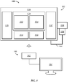
- FIG. 1 is a block diagram of one exemplary embodiment of an endoscopic visualization system 100, which includes a wireless endoscopic camera system 102 and a viewing station 160.
- the phrase "endoscopic camera system" will refer to an endoscope attached to an endoscopic camera and a light source.
- an endoscopic camera system according to the present application may be provided as only an endoscopic camera, a coupler for attaching the camera to an endoscope, and a light source.
- the coupler might not be included in the system.
- an endoscopic camera system may not include the endoscope itself, as this may be provided or available as a separate component. The embodiment shown in FIG.
- endoscopic visualization system 100 is a more inclusive system, because it includes endoscopic camera system 102 and viewing station 160.
- System 100 can be used for visualizing scenes of interest during an endoscopic procedure, such as the examination of sinus passages and cavities.
- Endoscopic camera system 102 captures video, images and/or other data and transmits the information to viewing station 160 for display.
- Endoscopic camera system 102 includes an endoscope 104, a light 106, a cable 108, and an endoscopic camera 110.
- Endoscope 104 guides light from a distal end of endoscope 104 near a scene of interest to a proximal end of endoscope 104, to provide a view for capture by endoscopic camera 110.
- Endoscope 104 includes a port for receiving illumination from light 106, which endoscope 104 uses to illuminate the scene of interest.
- endoscope 104 may be flexible or rigid and may have any of a variety shapes and sizes.
- endoscope 104 can take the form of a scope from the FocESSTM line of sinuscopes, provided by Entellus MedicalTM of Plymouth, Minnesota. Because endoscopes are generally well known, and because endoscopic camera system 102 may, in various embodiments, be used with any suitable endoscope 104, this application will not describe endoscope 104 in further detail.
- Light 106 is a source of illumination and can be coupled to endoscope 104.
- Light 106 can include light emitting diodes (LEDs) or other sources of illumination.
- Light 106 may include associated driver circuitry which is located in the endoscopic camera 110 or is external thereto.
- Light 106 can include its own power source or can receive power from an external source, such as endoscopic camera 110.
- light 106 can be coupled to endoscopic camera 110 via cable 108.
- Light 106 can have adjustable illumination settings. For example, such illumination settings may be adjustable by a signal (e.g., a signal from endoscopic camera 110), by a control panel on light 106, or in another manner.
- Endoscopic camera 110 captures a view (e.g., a view transmitted by endoscope 104) as video, images, or other data.
- Endoscopic camera 110 includes a camera 112, a battery 114, and a wireless transmitter 116.
- Camera 112 is a portion of endoscopic camera 110 that converts visual information received from endoscope 104 into electrical information.
- Battery 114 is a power source for endoscopic camera 110 and can also power light 106. Battery 114 can be removable by the user or be integrated into endoscopic camera 110. Battery 114 can take various forms and can be rechargeable (e.g., battery 114 can be a rechargeable lithium-ion battery).
- Wireless transmitter 116 can transmit data from endoscopic camera 110 to a receiver. In some embodiments, endoscopic camera 110 can be configured to also wirelessly receive data.
- Wireless transmitter 116 can be configured to communicate data over a variety of different protocols and may include associated hardware to transmit the data over a protocol. These protocols can include WirelessHDTM, BluetoothTM, WiFiTM, other protocols, and combinations thereof.
- Endoscopic camera 110 further includes one or more computing components, including a processing unit 118 and a memory 120.
- Processing unit 118 can be implemented using one or more processors (e.g., CPUs) or other circuitry for performing processing tasks.
- Memory 120 may be implemented using any suitable electronically accessible memory, including but not limited to RAM, ROM, Flash, SSD, or hard drives.
- Memory 120 includes executable instructions for adjusting illumination 122 and other executable instructions 124.
- Executable instructions for adjusting illumination 122 may include instructions executable by processing unit 118 for controlling illumination of the scene of interest by, for example, controlling power to light 106.
- Executable instructions for adjusting illumination 122 may include instructions for performing some of the steps described in relation to FIG. 11 .
- Other executable instructions 124 include other instructions for processing unit 118, including but not limited to instructions for white balancing data from camera 112, instructions for encoding data from camera 112, instructions for controlling wireless transmitter 116 (e.g., instructions for pairing wireless transmitter 116 with a receiver 162), instructions for controlling camera 112, and/or other instructions.
- Viewing station 160 is a station for receiving and viewing data from endoscopic camera system 102.
- Viewing station 160 includes a receiver 162 for receiving data transmitted by wireless transmitter 116 of endoscopic camera system 102.
- Monitor 164 is a device for displaying, storing, and/or otherwise acting on the data received at receiver 162.
- the receiver 162 may be physically separate from the monitor 164.
- the receiver 162 may be incorporated into the monitor 164.
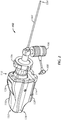
- FIG. 2 illustrates a perspective view of one embodiment of endoscopic camera system 102, including endoscope 104, light 106, cable 108, and endoscopic camera 110.
- endoscopic camera system 102 further includes a coupling 156 between endoscope 104 and endoscopic camera 110.
- Endoscopic camera 110 further includes a control panel 126, a battery latch 128, a tail portion 130, and a grip region 132.
- Endoscopic camera system 102 includes a proximal end 152 and a distal end 154. Distal end 154 may be located near the portion of endoscope 104 placed near the scene of interest.
- Proximal end 152 is located on an end of endoscopic camera 110.
- Control panel 126 includes one or more buttons, switches, slides, dials, or other input mechanisms for controlling the operation of endoscopic camera system 102. Controls can include a power control, an illumination control, a white balance control, a zoom control, controls for wireless transmission settings, and/or other controls. Control panel 126 can also include controls for manipulating how data is displayed at monitor 164.
- Battery latch 128 is a latch to hold battery 114 in place. Battery latch 128 may cooperate with other features to hold battery 114 in place. Battery latch 128 may be slidable to facilitate release of battery 114.
- Tail 130 can be a portion near proximal end 152 of endoscopic camera 110.
- tail 130 is an elongate portion having a relatively smaller height compared to an adjacent, more distal portion of endoscopic camera 110.
- tail 130 may begin at the end of battery latch 128, when battery latch 128 is in a closed position securing battery 114 in place.
- Tail 130 may be an area where wireless transmitter 116 or components thereof (e.g., an antenna) are located.
- Grip region 132 is a region of endoscopic camera system 102 adapted to be held by a user. Grip region 132 may configured to provide an ergonomic location for use of endoscopic camera system 102. In one embodiment, grip region 132 is located at or near a balance point of endoscopic camera system 102 to facilitate manipulation of endoscopic camera system 102 by a user. Grip region 132 may also be configured at a portion of endoscopic camera 110 that is a particular distance away from wireless transmitter 116. Designing camera 110 to position grip region 132 as far away as practicable from transmitter 116 may be advantageous, in that this configuration prevents the user's hand from interfering with data transmission from transmitter 116.
- the grip region 132 may be located more than 5 centimeters, away from wireless transmitter 116.
- Grip region 132 may include one or more features to facilitate holding by the user, including but not limited to those described below, in reference to FIGS. 3-5 .
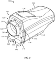
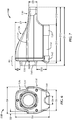
- FIG. 3 illustrates a perspective view of endoscopic camera 110, according to one embodiment.
- FIG. 4 illustrates a front view of grip region 132 of endoscopic camera 110 of FIG. 3 .
- FIG. 5 illustrates a side view of a distal end of endoscopic camera 110 of FIG. 3 .
- endoscopic camera 110 is presented without endoscope 104, light 106, cable 108, and coupling 156 of endoscopic camera system 102 to improve visibility of grip region 132 and other portions of endoscopic camera 110.
- Illustrated features include shoulders 134, which divide endoscopic camera 110 into a head portion 136 and a body portion 138.
- Illustrated features further include an attachment collar 140, a ledge 142, a first concavity 144, a second concavity 146, a divot 148, and a face 150.
- Shoulders 134 are an area of reduced width of endoscopic camera 110. In the illustrated example, shoulders 134 are located at approximately two-thirds of the way up the height of endoscopic camera 110 from the bottom of endoscopic camera 110, and shoulders 134 are an area having a width reduced by approximately fifteen percent. Shoulders 134 can provide a region to facilitate holding endoscopic camera 110. For example, a user may grip endoscopic camera 110 with one or more fingers or another part of the hand against or along one or both shoulders 134. In one embodiment, one or more of the user's fingers may be positioned substantially perpendicular to or parallel with one or both of shoulders 134. Endoscopic camera system 102 can be gripped by the user in a manner such that shoulders 134 resist unwanted rotation of endoscopic camera 110 relative to the user's hand. Shoulders 134 can further facilitate user-desired rotation of endoscopic camera 110 about the axis relative to the user's hand. Shoulders 134 can continue along a portion of the length of endoscopic camera 110 and continue along or be incorporated into tail 130.
- Shoulders 134 can divide endoscopic camera 110 into head 136 and body 138.
- Head 136 can be defined by a portion above shoulders 134 and/or body 138. In the illustrated example, head 136 extends above shoulders 134 and has a width decreasing from shoulders 134 to the top of head 136.
- the top of head 136 can include a curve configured to match a curve of a user's hand to facilitate placing the user's hand or a portion thereof on the top of head 136.
- the height of head 136 decreases along the length of endoscopic camera 110, such that head 136 forms a slope towards and/or into tail 130.
- Control panel 126 is disposed on the slope of head 136.
- Body 138 can be described as a portion below shoulders 134 and/or head 136. In the illustrated example, body 138 has a greater width than head 136 and the width of body 138 decreases towards ledge 142.
- Face 150 can be a region located at the distal end of endoscopic camera 110. Face 150 can be located within grip region 132 and may be substantially flat enough to facilitate use of grip region 132. For example, the user may wrap one or more fingers around attachment collar 140 and have a portion of the hand against face 150. In certain grips, face 150 can also be a portion of endoscopic camera 110 where a portion of the weight of endoscopic camera 110 rests against the user's hand and prevents unwanted distal movement of endoscopic camera 110 through the hand (see, e.g., FIG. 9 and FIG. 10 ).
- Attachment collar 140 is a location at or by which endoscopic camera 110 can be coupled to coupling 156.
- Attachment collar 140 can be a circular protrusion extending from endoscopic camera 110.
- Attachment collar 140 can take other forms, such as an opening in endoscopic camera 110 into which coupling 156 can be attached.
- attachment collar 140 is a circular protrusion from face 150 in grip region 132.
- Attachment collar 140 can be positioned substantially centered along the width of endoscopic camera 110 and positioned with its center substantially aligned with shoulders 134. In this manner, grip region 132 may facilitate gripping of endoscopic camera 110 using shoulders 134 and attachment collar 140.
- attachment collar 140 can be located within grip region 132 and facilitate user's holding of endoscopic camera system 102.
- attachment collar 140 can be located within grip region 132 and provide an area around which the user may grip to hold endoscopic camera system 102. In such a position, the user may grip attachment collar 140, coupling 156, or combinations thereof.
- Attachment collar 140 and coupling 156 may include features to facilitate holding, such as knurling.
- Ledge 142 is a protrusion from endoscopic camera 110 and can form a portion of grip region 132. Ledge 142 provides a region to facilitate holding endoscopic camera 110. For example, a user may grip endoscopic camera 110 with one or more fingers or another part of the hand against or along ledge 142. Endoscopic camera system 102 can be gripped by the user in a manner that ledge 142 resists unwanted distal or proximal motion of endoscopic camera 110 relative to the user's hand and to facilitate desired distal or proximal motion of endoscopic camera 110. Ledge 142 extends distally from face 150 and decreases in width as ledge 142 extends from face 150.
- Ledge 142 can include one or more features, such as a first concavity 144, a second concavity 146, and a divot 148.
- First concavity 144 and second concavity 146 can run along ledge 142, be separated by a convex portion of ledge 142, and provide a location for the user to place fingers or a portion of the user's hand to improve grip on ledge 142 or to facilitate control of endoscopic camera system 102 as a whole.
- Divot 148 can be a concave space in ledge 142.
- Divot 148 can be a grip enhancing feature.
- divot 148 can be a place at which the user may place a portion of the user's hand.
- Divot 148 can be adapted to provide a channel or other opening through which battery 114 may be manipulated.
- ledge 142 can cooperate with battery latch 128 to hold battery 114 in place.
- Battery 114 can be located proximal to ledge 142, and divot 148 can provide a channel through which the user can manipulate battery 114 to insert or remove battery 114.
- Grip region 132 can be configured to encourage or discourage a user to hold endoscopic camera system 102 in a particular way or location.
- grip region 132 can be located to encourage a user to hold endoscopic camera system 102 a particular distance away from wireless transmitter 116, such as 5 centimeters or more.
- Grip region 132 can be located to encourage a user to grab endoscopic camera system 102 a particular distance away from a balance point of endoscopic camera system 102, a particular distance away from wireless transmitter 116, or a combination thereof.
- endoscopic camera system 102 can be configured to have a balance point near grip region 132. The balance point can be located more than 5 centimeters away from wireless transmitter 116.
- Grip region 132 can be configured to provide multiple, complimentary features to facilitate grip.
- grip region 132 can be configured for a user to grip attachment collar 140 to control rotational movement of endoscopic camera system 102 relative to the user's hand.
- Grip region 132 can be further configured for a user to rest a portion of the user's hand or fingers within first concavity 144 to control proximal and distal movement of endoscopic camera system 102.
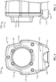
- FIGS. 6 and 7 are front and side views, respectively, of endoscopic camera 110, with labels illustrating dimensions of the various components and portions of endoscopic camera 110, according to one embodiment.
- the dimensions are meant to be exemplary in nature, applying to one embodiment, and any or all the dimensions may vary in alternative embodiments. Additionally, each exemplary dimension listed below may vary slightly, for example by approximately +/- 2.54mm (0.1 inch), without departing from the scope of the invention. Therefore, the dimensions listed below should be interpreted as examples only and should not be interpreted as limiting the scope of the invention as it is set forth in the claims.
- FIG. 6 illustrates example dimensions D1, D2, D3, D4, and D5.
- Distance D1 is the width of the widest portion of endoscopic camera 110. In the illustrated embodiment, distance D1 is also the width of endoscopic camera 110 measured as shoulders 134 begin. In one embodiment, distance D1 is approximately 55,88mm (2.20 inches). In various alternative embodiments D1 may be between about 27.94mm (1.10 inches) and about 83.82mm (3.30 inches), or more ideally between about 39.116mm (1.54 inches) and about 72,644mm (2.86 inches), or even more ideally between about 50.292mm (1.98 inches) and about 61.468mm (2.42 inches).
- Distance D2 is the width of one shoulder 134, or in other words a narrowing of the width of endoscopic camera 110 at each shoulder 134. In one embodiment, distance D2 is approximately 4.572mm (0.18 inches). In various alternative embodiments D2 may be between about 2.286mm (0.09 inches) and about 6.858mm (0.27 inches), or more ideally between about 3.302mm (0.13 inches) and about 5.842mm (0.23 inches), or even more ideally between about 4.064mm (0.16 inches) and about 5.08mm (0.20 inches).
- Distance D3 is the height of endoscopic camera 110 measured from a bottom of ledge 142 to a top of head 136. In one embodiment, distance D3 is approximately 70.866mm (2.79 inches).
- D3 may be between about 35.56mm (1.40 inches) and about 106.426mm (4.19 inches), or more ideally between about 49.784mm (1.96 inches) and about 92.202mm (3.63 inches), or even more ideally between about 63.5mm (2.5 inches) and about 77.978mm (3.07 inches).
- Distance D4 is the width of the widest part of divot 148. In one embodiment, distance D4 is approximately 17.272mm (0.68 inches).
- D4 may be between about 8.636mm (0.34 inches) and about 25.908mm (1.02 inches), or more ideally between about 12.192mm (0.48 inches) and about 22.352mm (0.88 inches), or even more ideally between about 15.494mm (0.61 inches) and about 19.05mm (0.75 inches).
- Distance D5 is the width of the widest part of ledge 142. In one embodiment, distance D5 is approximately 42.672mm (1.68 inches).
- D5 may be between about 21.336mm (0.84 inches) and about 64.008mm (2.52 inches), or more ideally between about 29.972mm (1.18 inches) and about 55.372mm (2.18 inches), or even more ideally between about 38.354mm (1.51 inches) and about 46.99mm (1.85 inches).
- FIG. 7 illustrates example dimensions D6, D7, D8, D9, D10, D11, D12, D13, and D14 and region R1.
- Distance D6 is the distance from a top portion of attachment collar 140 to the top of endoscopic camera 110 (e.g., top of head 136). In one embodiment, distance D6 is approximately 10.16mm (0.40 inches). In various alternative embodiments D6 may be between about 5.08mm (0.20 inches) and about 15.24mm (0.60 inches), or more ideally between about 7.112mm (0.28 inches) and about 13.208mm (0.52 inches), or even more ideally between about 9.144mm (0.36 inches) and about 11.176mm (0.44 inches).
- Distance D7 is the distance from a top of shoulders 134 to the top of endoscopic camera 110 (e.g., top of head 136). In one embodiment, distance D7 is approximately 22.86mm (0.90 inches). In various alternative embodiments D7 may be between about 11.43mm (0.45 inches) and about 34.29mm (1.35 inches), or more ideally between about 16.002mm (0.63 inches) and about 29.718mm (1.17 inches), or even more ideally between about 20.574mm (0.81 inches) and about 25.146mm (0.99 inches).
- Distance D8 is the distance that attachment collar 140 extends from face 150 of grip region 132. In one embodiment, distance D8 is approximately 9.652mm (0.38 inches).
- D8 may be between about 4.826mm (0.19 inches) and about 14.478mm (0.57 inches), or more ideally between about 6.858mm (0.27 inches) and about 12.446mm (0.49 inches), or even more ideally between about 8.636mm (0.34 inches) and about 10.668mm (0.42 inches).
- Distance D9 is the height of tail 130. In one embodiment, distance D9 is approximately 16.764mm (0.66 inches).
- D9 may be between about 8.382mm (0.33 inches) and about 25.146mm (0.99 inches), or more ideally between about 11.684mm (0.46 inches) and about 21.844mm (0.86 inches), or even more ideally between about 14.986mm (0.59 inches) and about 18.542mm (0.73 inches).
- Distance D10 is the distance from the bottom of attachment collar 140 to a middle of ledge 142. In one embodiment, distance D10 is approximately 20.574mm (0.81 inches).
- D10 may be between about 10.414mm (0.41 inches) and about 30.988mm (1.22 inches), or more ideally between about 14.478mm (0.57 inches) and about 26.67mm (1.05 inches), or even more ideally between about 18.542mm (0.73 inches) and about 22.606mm (0.89 inches).
- Distance D11 is the distance from the distal end of ledge 142 to the proximal end of battery latch 128. In one embodiment, distance D11 is approximately 80.518mm (3.17 inches).
- D11 may be between about 40.386mm (1.59 inches) and about 120.904mm (4.76 inches), or more ideally between about 56.388mm (2.22 inches) and about 104.648mm (4.12 inches), or even more ideally between about 72.39mm (2.85 inches) and about 88.646mm (3.49 inches).
- Distance D12 is the distance the proximal end of battery latch 128 to the proximal end of tail 130. This can also be described as the width of tail 130. In one embodiment, distance D12 is approximately 36.576mm (1.44 inches).
- D12 may be between about 18.288mm (0.72 inches) and about 54.864mm (2.16 inches), or more ideally between about 25.654mm (1.01 inches) and about 47.498mm (1.87 inches), or even more ideally between about 33.02mm (1.30 inches) and about 40.132mm (1.58 inches).
- Distance D13 is the distance from face 150 to the proximal end of tail 130. In one embodiment, distance D13 is approximately 112.522mm (4.43 inches).
- D13 may be between about 56.388mm (2.22 inches) and about 168.91mm (6.65 inches), or more ideally between about 78.74mm (3.10 inches) and about 146.304mm (5.76 inches), or even more ideally between about 101.346mm (3.99 inches) and about 123.698mm (4.87 inches).
- Distance D14 is the distance from the distal end of attachment collar 140 to the proximal end of tail 130. In one embodiment, distance D14 is approximately 121.92mm (4.80 inches).
- D14 may be between about 50.8mm (2.40 inches) and about 177.8mm (7.20 inches), or more ideally between about 85.344mm (3.36 inches) and about 158.496mm (6.24 inches), or even more ideally between about 109.728mm (4.32 inches) and about 134.112mm (5.28 inches).
- region R1 is the region in which the balance point of endoscopic camera system 102 is located. The region R1 is approximately centered at face 150.
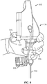
- FIG. 8 illustrates a method for gripping endoscopic camera system 102, according to one embodiment.
- the user's thumb is placed against ledge 142 with a portion of the thumb in second concavity 146.
- the user's index finger is placed on top of head 136, and the index finger may rest on a curve of head 136 configured to receive a portion of a user's hand.
- the remaining fingers are placed against coupling 156.
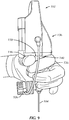
- FIG. 9 illustrates an alternative embodiment of a method for gripping endoscopic camera system 102.
- the user's thumb is placed against, and at least partially within, first concavity 144 in ledge 142.
- the user's thumb is also placed against face 150.
- the user's index finger is wrapped partially around attachment collar 140 with a portion of the finger resting against face 150 and with the end of the finger resting against coupling 156.
- the user's index finger and thumb may at least partially support the weight of endoscopic camera system 102 where face 150 meets the user's index finger and thumb and where first concavity 144 meets the user's thumb.
- the user's remaining fingers are also placed against coupling 156. These fingers may provide additional control of and support for endoscopic camera system 102.
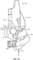
- FIG. 10 illustrates another alternative embodiment of a method for gripping an endoscopic camera system 102.
- the user's thumb is placed against, and at least partially within, first concavity 144 in ledge 142.
- the user's thumb is also placed against face 150.
- the user's thumb may at least partially support the weight of endoscopic camera system 102 where the thumb contacts first concavity 144 and face 150.
- the user's index finger is wrapped partially around attachment collar 140 and coupling 156, with the end of the finger resting against coupling 156.
- the user's remaining fingers are draped along coupling 156 and endoscope 104 with some of the ends of the fingers resting against light 106.
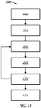
- FIG. 11 illustrates one embodiment of a method 200 for visualizing a scene of interest with an endoscope by modulating illumination output to correct for overexposure or underexposure.
- video capture parameters such as exposure time or sensor gain
- illumination output of a light may be the primary parameter modified to affect exposure of video, while video capture parameters affecting exposure remain substantially constant.
- modifying the illumination can be used to improve battery life of the system and decrease heat output. This can be done by, for example, keeping video capture parameters affecting exposure at a relatively high setting (e.g., settings tending to cause overexposure), which allows for illumination output to be relatively reduced. Reduced illumination output can beneficially reduce battery draw and heat output for the illumination source. With exposure parameters at a relatively high setting, less illumination is needed to properly expose the scene than would be required if the video capture parameters were reduced.
- the method 200 may start by advancing the distal end of an endoscopic camera system to a scene of interest 202.
- the endoscopic camera system may be used to illuminate the scene of interest 204.
- a video signal can then be captured by the system 206, and a processor of the system may be used to determine exposure of the video signal 208. If the processor determines that the video signal is overexposed or underexposed, it can then send a signal to change the illumination output from the light source 210.
- the method may then continue by removing the endoscopic camera system 212 or by continuing capturing video using the changed illumination output 206.
- the process 200 can include various preparatory steps, including but not limited to selecting components of endoscopic camera system 102 (e.g., endoscope 104, light 106, and endoscopic camera 110), assembling endoscopic camera system 102 (e.g., optically connecting endoscope 104 to endoscopic camera 110 via coupling 156), establishing communication between wireless transmitter 116 and receiver 162, calibrating endoscopic camera system 102 and monitor 164, sterilizing endoscopic camera system 102, preparing the subject for the procedure, or other preparatory steps.
- endoscopic camera system 102 e.g., endoscope 104, light 106, and endoscopic camera 110
- assembling endoscopic camera system 102 e.g., optically connecting endoscope 104 to endoscopic camera 110 via coupling 156
- establishing communication between wireless transmitter 116 and receiver 162 calibrating endoscopic camera system 102 and monitor 164
- sterilizing endoscopic camera system 102 preparing the subject for the procedure, or other preparatory steps.
- Block 202 recites "advancing distal end to scene of interest.”
- the user can advance distal end 154 of endoscopic camera system 102 toward a scene of interest.
- process 200 can be used for visualizing a scene of interest during a procedure in a subject's sinus cavity, and the distal end of endoscopic camera system 102 can be advanced through subject's nostril or an access hole in subject's gingival tissue towards subject's sinus cavity.
- Block 204 recites "illuminating scene of interest.”
- light 106 can be used to provide illumination at the scene of interest.
- light 106 can shine into a proximal end of endoscope 104, and endoscope 104 transmits the light down the length of the scope and out distal end 154 to illuminate the scene of interest.
- This illumination can be used to facilitate the capture of video information using endoscopic camera system 102.
- the illumination can be provided according to various parameters.
- Light 106 can provide illumination at a particular illumination output that can be varied (e.g., measured in lumens) manually by the user, automatically by the endoscopic camera 110 (e.g., by providing a signal through cable 108), or combinations thereof.
- output of light 106 is controlled by pulse width modulation of a signal.
- the duty cycle can be varied to increase or decrease the output of light 106.
- Block 206 recites "capturing video.”
- Visual information at distal end 154 can travel down endoscope 104 and received at camera 112 in endoscopic camera 110.
- Camera 112 can convert the visual information into electrical signals. These signals can be transmitted to receiver 162 for display at monitor 164.
- the signals may undergo processing at camera 112, endoscopic camera 110, or elsewhere.
- the processing can include white balancing, filtering, noise reduction, level adjustments, color adjustments, compression, and other processing.
- Camera 112 may operate according to particular parameters, for example camera 112 can operate according to video capture characteristics that affect exposure of the resulting video. These characteristics can include, but need not be limited to shutter speed, exposure time, and imaging sensor sensitivity to light. These characteristics can be preset to maximize exposure of the resulting video, such as by decreasing shutter speed, increasing exposure time, and increasing imaging sensor sensitivity. Other parameters can include resolution, compression, frame rate, white balance, and other parameters.
- Block 208 recites "determining exposure.”
- the signal from camera 112 can be analyzed to determine the exposure of one or more frames of the video image. This analysis can be performed within camera 112, on processing unit 118 or elsewhere. In one embodiment, this analysis can be performed by measuring a distribution of the brightness value of pixels that make up one or more video frames. Responsive to a first threshold number of pixels being within a threshold region, the image may be determined to be improperly exposed. In another example, this analysis can be performed by averaging the pixel value in one or more frames and determining whether the resulting value is past an overexposure or underexposure threshold.
- the brightness may be determined based on received input from the user (e.g., the user pushes an "increase brightness" button, which may indicate that the video is underexposed).
- the result of block 208 may be a determination whether one or more frames of a video signal are underexposed, properly exposed, or overexposed. Another result may be a measurement of how overexposed or underexposed the one or more frames are.
- Block 210 recites "changing illumination output.” Responsive to the video signal being underexposed or overexposed, the illumination output can be modified. For example, if the video signal is underexposed, the illumination output can be increased to bring the signal to proper exposure. If the video signal is overexposed, the illumination output can be decreased to bring the signal to proper exposure.
- Changing illumination output can be performed instead of or in addition to changing camera settings. For example, the exposure may be corrected by maintaining the same video capture characteristics that produced the overexposed or underexposed frame and changing the illumination output of light 106. The amount by which illumination output is changed can depend on various parameters, including whether illumination output is the only variable being changed, an amount of exposure or underexposure, whether previous frames were also overexposed or underexposed, and/or other parameters.
- illumination output may be limited, to avoid potentially undesirable rapid changing of illumination.
- illumination output is changed responsive to a threshold number of frames being improperly exposed. For instance, the illumination output is increased after 12 frames being underexposed.
- changes to illumination output may be capped at a certain number of frames (e.g., illumination output cannot be changed more than once every 24 frames).
- the process of capturing video, determining exposure, and changing illumination output in blocks 206, 208, and 210 may repeat until, for example, the user intervenes (e.g., by turning off video capture at the completion of the procedure).
- Block 212 recites "removing endoscope.”
- the process 200 can conclude with endoscopic camera system 102 being removed from the scene of interest and the subject, such as at the completion of the procedure.
- system elements may be implemented as computer-readable instructions (e.g., software) on one or more computing devices (e.g., servers, personal computers, etc.), stored on computer readable media associated therewith (e.g., disks, memories, etc.).
- computing devices e.g., servers, personal computers, etc.
- computer readable media e.g., disks, memories, etc.
- a computer program product may have such instructions stored on computer readable media for carrying out the functions described herein.
Landscapes
- Health & Medical Sciences (AREA)
- Life Sciences & Earth Sciences (AREA)
- Surgery (AREA)
- Engineering & Computer Science (AREA)
- Optics & Photonics (AREA)
- Physics & Mathematics (AREA)
- Biomedical Technology (AREA)
- Veterinary Medicine (AREA)
- Biophysics (AREA)
- Pathology (AREA)
- Radiology & Medical Imaging (AREA)
- Nuclear Medicine, Radiotherapy & Molecular Imaging (AREA)
- Public Health (AREA)
- Heart & Thoracic Surgery (AREA)
- Medical Informatics (AREA)
- Molecular Biology (AREA)
- Animal Behavior & Ethology (AREA)
- General Health & Medical Sciences (AREA)
- Signal Processing (AREA)
- Multimedia (AREA)
- Computer Networks & Wireless Communication (AREA)
- Microelectronics & Electronic Packaging (AREA)
- Endoscopes (AREA)
- Instruments For Viewing The Inside Of Hollow Bodies (AREA)
- Optical Fibers, Optical Fiber Cores, And Optical Fiber Bundles (AREA)
- Ultra Sonic Daignosis Equipment (AREA)
Applications Claiming Priority (2)
| Application Number | Priority Date | Filing Date | Title |
|---|---|---|---|
| US201662385892P | 2016-09-09 | 2016-09-09 | |
| PCT/US2017/017199 WO2018048466A1 (en) | 2016-09-09 | 2017-02-09 | Wireless endoscope |
Publications (3)
| Publication Number | Publication Date |
|---|---|
| EP3509471A1 EP3509471A1 (en) | 2019-07-17 |
| EP3509471A4 EP3509471A4 (en) | 2019-10-30 |
| EP3509471B1 true EP3509471B1 (en) | 2021-06-30 |
Family
ID=61562243
Family Applications (1)
| Application Number | Title | Priority Date | Filing Date |
|---|---|---|---|
| EP17849222.9A Active EP3509471B1 (en) | 2016-09-09 | 2017-02-09 | Wireless endoscope |
Country Status (6)
| Country | Link |
|---|---|
| US (3) | US11191421B2 (cg-RX-API-DMAC7.html) |
| EP (1) | EP3509471B1 (cg-RX-API-DMAC7.html) |
| JP (1) | JP6878574B2 (cg-RX-API-DMAC7.html) |
| CN (1) | CN109688896B (cg-RX-API-DMAC7.html) |
| AU (2) | AU2017325566B2 (cg-RX-API-DMAC7.html) |
| WO (1) | WO2018048466A1 (cg-RX-API-DMAC7.html) |
Families Citing this family (11)
| Publication number | Priority date | Publication date | Assignee | Title |
|---|---|---|---|---|
| JP6878574B2 (ja) * | 2016-09-09 | 2021-05-26 | エンテラス メディカル インコーポレイテッドEntellus Medical,Inc. | 無線内視鏡 |
| ES2955917T3 (es) * | 2017-02-15 | 2023-12-11 | Lazurite Holdings Llc | Sistema médico inalámbrico de formación de imágenes que comprende unidad de cabezal y cable de luz que comprende fuente luminosa integrada |
| USD976398S1 (en) | 2019-10-28 | 2023-01-24 | Integrated Endoscopy, Inc. | Wireless camera |
| USD937769S1 (en) | 2019-10-28 | 2021-12-07 | Integrated Endoscopy, Inc. | Charging base for a wireless camera |
| USD937768S1 (en) | 2019-10-28 | 2021-12-07 | Integrated Endoscopy, Inc. | Charging base for a wireless camera |
| EP4093260A4 (en) * | 2020-01-24 | 2024-06-05 | Integrated Endoscopy, Inc. | WIRELESS CAMERA SYSTEM FOR ENDOSCOPE |
| CN113799065A (zh) * | 2020-06-16 | 2021-12-17 | 杭州巨星智能科技有限公司 | 可视化操作装置 |
| CN114125225B (zh) * | 2021-11-18 | 2023-03-24 | 浙江大学 | 一种内窥镜亮度自动调节方法及装置、系统、电子设备 |
| AU2023209891A1 (en) * | 2022-01-24 | 2024-08-15 | Lazurite Holdings Llc | Wireless imaging system |
| US11774833B2 (en) * | 2022-02-09 | 2023-10-03 | Nikola Vladimir Bicanic | Methods, systems, apparatuses, and devices for facilitating controlling operation of a content capturing device |
| US12268359B2 (en) * | 2023-03-13 | 2025-04-08 | Endoluxe Inc. | Handheld unit for endoscopy, laparoscopy, and other scopic procedures and methods of manufacture and use thereof |
Family Cites Families (61)
| Publication number | Priority date | Publication date | Assignee | Title |
|---|---|---|---|---|
| JPS55138437A (en) * | 1979-04-16 | 1980-10-29 | Olympus Optical Co | Camera for endoscope |
| JPH02135413A (ja) * | 1988-11-17 | 1990-05-24 | Olympus Optical Co Ltd | 内視鏡装置 |
| JPH02289222A (ja) * | 1989-04-28 | 1990-11-29 | Fuji Photo Optical Co Ltd | 内視鏡 |
| USD326714S (en) | 1989-06-16 | 1992-06-02 | Olympus Optical Co., Ltd. | Endoscope for blood vessel |
| JPH0710733Y2 (ja) * | 1989-11-07 | 1995-03-15 | オリンパス光学工業株式会社 | レゼクトハンドル |
| US5399164A (en) * | 1992-11-02 | 1995-03-21 | Catheter Imaging Systems | Catheter having a multiple durometer |
| US6554765B1 (en) * | 1996-07-15 | 2003-04-29 | East Giant Limited | Hand held, portable camera with adaptable lens system |
| US5921956A (en) * | 1997-09-24 | 1999-07-13 | Smith & Nephew, Inc. | Surgical instrument |
| US6589162B2 (en) | 2000-02-21 | 2003-07-08 | Pentax Corporation | Endoscope system and video camera for endoscope |
| JP2001286440A (ja) * | 2000-04-10 | 2001-10-16 | Asahi Optical Co Ltd | 携帯内視鏡のテレビ装置 |
| US20060135846A1 (en) * | 2004-12-17 | 2006-06-22 | Hunt John V | Endoscopic device and component attachable to an endoscope handpiece |
| EP1841353A4 (en) * | 2004-12-28 | 2011-09-21 | Patrick C Melder | SYSTEM FOR ENDOSCOPIC IMAGING |
| USD553242S1 (en) | 2005-09-27 | 2007-10-16 | Allegiance Corporation | Handle for surgical suction-irrigation device |
| USD548328S1 (en) | 2005-09-27 | 2007-08-07 | Allegiance Corporation | Handle for surgical suction-irrigation device |
| US8657846B2 (en) | 2006-04-21 | 2014-02-25 | Entellus Medical, Inc. | Guide catheter and method of use |
| US7520876B2 (en) | 2006-04-21 | 2009-04-21 | Entellus Medical, Inc. | Device and method for treatment of sinusitis |
| JP5395671B2 (ja) * | 2006-11-16 | 2014-01-22 | ストライカー・コーポレーション | 無線内視鏡カメラ |
| US20080172033A1 (en) | 2007-01-16 | 2008-07-17 | Entellus Medical, Inc. | Apparatus and method for treatment of sinusitis |
| US8241266B2 (en) | 2007-04-05 | 2012-08-14 | Entellus Medical, Inc. | Apparatus and method for treatment of ethmoids |
| US8801670B2 (en) | 2008-02-27 | 2014-08-12 | Entellus Medical, Inc. | Apparatus and method for accessing a sinus cavity |
| JP5464817B2 (ja) | 2008-04-01 | 2014-04-09 | オリンパスメディカルシステムズ株式会社 | 手持式内視鏡 |
| US10064697B2 (en) * | 2008-10-06 | 2018-09-04 | Santa Anna Tech Llc | Vapor based ablation system for treating various indications |
| US9561068B2 (en) * | 2008-10-06 | 2017-02-07 | Virender K. Sharma | Method and apparatus for tissue ablation |
| US20110009694A1 (en) * | 2009-07-10 | 2011-01-13 | Schultz Eric E | Hand-held minimally dimensioned diagnostic device having integrated distal end visualization |
| EP3610778B1 (en) | 2008-11-18 | 2023-07-05 | Stryker Corporation | Endoscopic led light source having a feedback control system |
| EP2359598A1 (en) * | 2008-11-21 | 2011-08-24 | Stryker Corporation | Wireless operating room communication system including video output device and video display |
| US9101739B2 (en) | 2009-02-17 | 2015-08-11 | Entellus Medical, Inc. | Balloon catheter inflation apparatus and methods |
| US9333327B2 (en) | 2009-04-24 | 2016-05-10 | Entellus Medical, Inc. | Methods and devices for paranasal sinus drug delivery |
| USD619708S1 (en) | 2009-05-29 | 2010-07-13 | Marc Ellman | Ophthalmoscope |
| US8282667B2 (en) | 2009-06-05 | 2012-10-09 | Entellus Medical, Inc. | Sinus dilation catheter |
| US8834513B2 (en) | 2009-06-05 | 2014-09-16 | Entellus Medical, Inc. | Method and articles for treating the sinus system |
| US8363097B2 (en) * | 2009-07-23 | 2013-01-29 | Smith & Nephew, Inc. | Endoscopic imaging system |
| US8888686B2 (en) | 2009-09-23 | 2014-11-18 | Entellus Medical, Inc. | Endoscope system for treatment of sinusitis |
| JP5642373B2 (ja) * | 2009-10-23 | 2014-12-17 | オリンパス株式会社 | 携帯無線端末、無線通信システムおよび携帯無線端末の無線通信方法 |
| USD639428S1 (en) | 2010-02-19 | 2011-06-07 | Olympus Medical Systems Corp | Portion of a camera for medical use |
| WO2011130639A1 (en) | 2010-04-15 | 2011-10-20 | Entellus Medical, Inc. | Method and apparatus for treating dilating the ethmoid infundibulum |
| WO2011140535A1 (en) | 2010-05-07 | 2011-11-10 | Entellus Medical, Inc. | Sinus balloon dilation catheters and sinus surgury tools |
| US8616085B2 (en) | 2010-08-18 | 2013-12-31 | Shimano Inc. | Bicycle crank assembly |
| US8323181B2 (en) * | 2011-02-17 | 2012-12-04 | Apurba Mukherjee | Endoscope with variable incident light and laser source platform |
| DE102011007484A1 (de) * | 2011-04-15 | 2012-10-18 | Henke-Sass, Wolf Gmbh | Endoskop mit variabler Blickrichtung |
| US9486614B2 (en) | 2011-06-29 | 2016-11-08 | Entellus Medical, Inc. | Sinus dilation catheter |
| US8878920B2 (en) * | 2011-07-12 | 2014-11-04 | Karl Storz Imaging, Inc. | Method and apparatus for protection from high intensity light |
| US9283360B2 (en) | 2011-11-10 | 2016-03-15 | Entellus Medical, Inc. | Methods and devices for treating sinusitis |
| US10143358B2 (en) * | 2012-02-07 | 2018-12-04 | Treble Innovations, Llc | System and method for a magnetic endoscope |
| US20140052004A1 (en) | 2012-08-15 | 2014-02-20 | Arthrex, Inc. | Endoscopic camera illumination system and method |
| US9107573B2 (en) * | 2012-10-17 | 2015-08-18 | Karl Storz Endovision, Inc. | Detachable shaft flexible endoscope |
| US9060404B2 (en) | 2012-11-20 | 2015-06-16 | RedBeard Ventures LLC | Synchronized light source for rolling shutter imagers |
| USD823463S1 (en) | 2012-12-14 | 2018-07-17 | Retractable Technologies, Inc. | Frontal attachment for medical device |
| US20140221740A1 (en) * | 2013-02-05 | 2014-08-07 | Paul John Kawula | Wireless endoscopic surgical device |
| CN104000548B (zh) * | 2013-02-22 | 2017-08-04 | 深圳先进技术研究院 | 用于三维尺寸测量的双目光电式内窥镜及内窥系统 |
| USD753296S1 (en) | 2014-01-31 | 2016-04-05 | Deka Products Limited Partnership | Endoscope |
| US9648100B2 (en) | 2014-03-05 | 2017-05-09 | Commvault Systems, Inc. | Cross-system storage management for transferring data across autonomous information management systems |
| USD782039S1 (en) | 2014-11-07 | 2017-03-21 | Karl Storz Gmbh & Co. Kg | Nephroscope |
| JP1524511S (cg-RX-API-DMAC7.html) | 2014-12-16 | 2015-05-25 | ||
| USD771252S1 (en) | 2014-12-25 | 2016-11-08 | Olympus Corporation | Body of a camera for medical use |
| CN104605806B (zh) * | 2015-01-06 | 2016-04-27 | 谢宏武 | 便携式实时成像内窥镜 |
| US10874287B2 (en) * | 2015-02-23 | 2020-12-29 | Uroviu Corp. | Handheld surgical endoscope |
| USD793554S1 (en) | 2015-04-30 | 2017-08-01 | Olympus Corporation | Endoscope video processor |
| US20170007282A1 (en) | 2015-07-08 | 2017-01-12 | Entellus Medical, Inc. | Turbinate compressors and methods of use |
| USD790697S1 (en) | 2015-07-31 | 2017-06-27 | Covidien Lp | Endoscope with oblique tip |
| JP6878574B2 (ja) * | 2016-09-09 | 2021-05-26 | エンテラス メディカル インコーポレイテッドEntellus Medical,Inc. | 無線内視鏡 |
-
2017
- 2017-02-09 JP JP2019513026A patent/JP6878574B2/ja active Active
- 2017-02-09 EP EP17849222.9A patent/EP3509471B1/en active Active
- 2017-02-09 CN CN201780054899.7A patent/CN109688896B/zh active Active
- 2017-02-09 AU AU2017325566A patent/AU2017325566B2/en active Active
- 2017-02-09 US US16/330,708 patent/US11191421B2/en active Active
- 2017-02-09 WO PCT/US2017/017199 patent/WO2018048466A1/en not_active Ceased
-
2021
- 2021-10-26 US US17/510,776 patent/US11779199B2/en active Active
-
2022
- 2022-12-01 AU AU2022279501A patent/AU2022279501B2/en active Active
-
2023
- 2023-09-18 US US18/369,589 patent/US12171409B2/en active Active
Also Published As
| Publication number | Publication date |
|---|---|
| JP6878574B2 (ja) | 2021-05-26 |
| JP2019526374A (ja) | 2019-09-19 |
| AU2017325566B2 (en) | 2022-09-22 |
| CN109688896B (zh) | 2023-06-27 |
| WO2018048466A1 (en) | 2018-03-15 |
| AU2017325566A1 (en) | 2019-03-21 |
| AU2022279501A1 (en) | 2023-02-02 |
| EP3509471A1 (en) | 2019-07-17 |
| CN109688896A (zh) | 2019-04-26 |
| US12171409B2 (en) | 2024-12-24 |
| US20240041308A1 (en) | 2024-02-08 |
| US11191421B2 (en) | 2021-12-07 |
| US11779199B2 (en) | 2023-10-10 |
| EP3509471A4 (en) | 2019-10-30 |
| AU2022279501B2 (en) | 2025-02-27 |
| CA3036179A1 (en) | 2018-03-15 |
| US20210038053A1 (en) | 2021-02-11 |
| US20220039633A1 (en) | 2022-02-10 |
Similar Documents
| Publication | Publication Date | Title |
|---|---|---|
| AU2022279501B2 (en) | Wireless endoscope | |
| JP4240892B2 (ja) | ディスプレイ一体型口腔カメラ | |
| EP1847214B1 (en) | Ultra wide band wireless optical endoscopic device | |
| US9517010B2 (en) | Ophthalmic instruments | |
| AU2019209147B2 (en) | Visualization devices and methods for otologic procedures | |
| CN106659371B (zh) | 医用观察设备 | |
| US20230255465A1 (en) | Laryngoscope With Video Capture | |
| KR101651604B1 (ko) | 치과용 구강 검사 시스템 | |
| WO2019211939A1 (ja) | 内視鏡装置 | |
| CA3036179C (en) | Wireless endoscope | |
| CN113677255A (zh) | 无线内窥镜装置 | |
| KR101567838B1 (ko) | 접이식 내시경 | |
| JP6116438B2 (ja) | 電子内視鏡システム及びその使用条件設定方法 | |
| JP2005342400A (ja) | 内視鏡装置及び内視鏡システム | |
| US20250235088A1 (en) | Tool drive adaptor for robotic surgical instrument | |
| US20230283892A1 (en) | Handheld wireless endoscope image streaming apparatus | |
| KR101191455B1 (ko) | 휴대용 검이경 | |
| KR20170038597A (ko) | 다용도 무선 자가 검이경 | |
| JP2004187865A (ja) | 機器システム |
Legal Events
| Date | Code | Title | Description |
|---|---|---|---|
| STAA | Information on the status of an ep patent application or granted ep patent |
Free format text: STATUS: THE INTERNATIONAL PUBLICATION HAS BEEN MADE |
|
| PUAI | Public reference made under article 153(3) epc to a published international application that has entered the european phase |
Free format text: ORIGINAL CODE: 0009012 |
|
| STAA | Information on the status of an ep patent application or granted ep patent |
Free format text: STATUS: REQUEST FOR EXAMINATION WAS MADE |
|
| 17P | Request for examination filed |
Effective date: 20190305 |
|
| AK | Designated contracting states |
Kind code of ref document: A1 Designated state(s): AL AT BE BG CH CY CZ DE DK EE ES FI FR GB GR HR HU IE IS IT LI LT LU LV MC MK MT NL NO PL PT RO RS SE SI SK SM TR |
|
| AX | Request for extension of the european patent |
Extension state: BA ME |
|
| RIC1 | Information provided on ipc code assigned before grant |
Ipc: H04N 5/225 20060101ALI20190617BHEP Ipc: A61B 1/045 20060101ALI20190617BHEP Ipc: H04N 5/235 20060101ALI20190617BHEP Ipc: A61B 1/04 20060101ALI20190617BHEP Ipc: H04N 5/232 20060101ALI20190617BHEP Ipc: A61B 1/06 20060101AFI20190617BHEP Ipc: A61B 1/00 20060101ALI20190617BHEP |
|
| A4 | Supplementary search report drawn up and despatched |
Effective date: 20190926 |
|
| RIC1 | Information provided on ipc code assigned before grant |
Ipc: H04N 5/232 20060101ALI20190920BHEP Ipc: A61B 1/00 20060101ALI20190920BHEP Ipc: A61B 1/06 20060101AFI20190920BHEP Ipc: A61B 1/04 20060101ALI20190920BHEP Ipc: H04N 5/235 20060101ALI20190920BHEP Ipc: H04N 5/225 20060101ALI20190920BHEP Ipc: A61B 1/045 20060101ALI20190920BHEP |
|
| DAV | Request for validation of the european patent (deleted) | ||
| DAX | Request for extension of the european patent (deleted) | ||
| GRAP | Despatch of communication of intention to grant a patent |
Free format text: ORIGINAL CODE: EPIDOSNIGR1 |
|
| STAA | Information on the status of an ep patent application or granted ep patent |
Free format text: STATUS: GRANT OF PATENT IS INTENDED |
|
| INTG | Intention to grant announced |
Effective date: 20210119 |
|
| GRAS | Grant fee paid |
Free format text: ORIGINAL CODE: EPIDOSNIGR3 |
|
| GRAA | (expected) grant |
Free format text: ORIGINAL CODE: 0009210 |
|
| STAA | Information on the status of an ep patent application or granted ep patent |
Free format text: STATUS: THE PATENT HAS BEEN GRANTED |
|
| AK | Designated contracting states |
Kind code of ref document: B1 Designated state(s): AL AT BE BG CH CY CZ DE DK EE ES FI FR GB GR HR HU IE IS IT LI LT LU LV MC MK MT NL NO PL PT RO RS SE SI SK SM TR |
|
| REG | Reference to a national code |
Ref country code: CH Ref legal event code: EP |
|
| REG | Reference to a national code |
Ref country code: DE Ref legal event code: R082 Ref document number: 602017041405 Country of ref document: DE Representative=s name: WUESTHOFF & WUESTHOFF, PATENTANWAELTE PARTG MB, DE |
|
| REG | Reference to a national code |
Ref country code: AT Ref legal event code: REF Ref document number: 1405569 Country of ref document: AT Kind code of ref document: T Effective date: 20210715 |
|
| REG | Reference to a national code |
Ref country code: DE Ref legal event code: R096 Ref document number: 602017041405 Country of ref document: DE |
|
| REG | Reference to a national code |
Ref country code: IE Ref legal event code: FG4D Ref country code: NL Ref legal event code: FP |
|
| REG | Reference to a national code |
Ref country code: LT Ref legal event code: MG9D |
|
| PG25 | Lapsed in a contracting state [announced via postgrant information from national office to epo] |
Ref country code: BG Free format text: LAPSE BECAUSE OF FAILURE TO SUBMIT A TRANSLATION OF THE DESCRIPTION OR TO PAY THE FEE WITHIN THE PRESCRIBED TIME-LIMIT Effective date: 20210930 Ref country code: HR Free format text: LAPSE BECAUSE OF FAILURE TO SUBMIT A TRANSLATION OF THE DESCRIPTION OR TO PAY THE FEE WITHIN THE PRESCRIBED TIME-LIMIT Effective date: 20210630 Ref country code: FI Free format text: LAPSE BECAUSE OF FAILURE TO SUBMIT A TRANSLATION OF THE DESCRIPTION OR TO PAY THE FEE WITHIN THE PRESCRIBED TIME-LIMIT Effective date: 20210630 |
|
| REG | Reference to a national code |
Ref country code: AT Ref legal event code: MK05 Ref document number: 1405569 Country of ref document: AT Kind code of ref document: T Effective date: 20210630 |
|
| PG25 | Lapsed in a contracting state [announced via postgrant information from national office to epo] |
Ref country code: NO Free format text: LAPSE BECAUSE OF FAILURE TO SUBMIT A TRANSLATION OF THE DESCRIPTION OR TO PAY THE FEE WITHIN THE PRESCRIBED TIME-LIMIT Effective date: 20210930 Ref country code: LV Free format text: LAPSE BECAUSE OF FAILURE TO SUBMIT A TRANSLATION OF THE DESCRIPTION OR TO PAY THE FEE WITHIN THE PRESCRIBED TIME-LIMIT Effective date: 20210630 Ref country code: RS Free format text: LAPSE BECAUSE OF FAILURE TO SUBMIT A TRANSLATION OF THE DESCRIPTION OR TO PAY THE FEE WITHIN THE PRESCRIBED TIME-LIMIT Effective date: 20210630 Ref country code: SE Free format text: LAPSE BECAUSE OF FAILURE TO SUBMIT A TRANSLATION OF THE DESCRIPTION OR TO PAY THE FEE WITHIN THE PRESCRIBED TIME-LIMIT Effective date: 20210630 Ref country code: GR Free format text: LAPSE BECAUSE OF FAILURE TO SUBMIT A TRANSLATION OF THE DESCRIPTION OR TO PAY THE FEE WITHIN THE PRESCRIBED TIME-LIMIT Effective date: 20211001 |
|
| PG25 | Lapsed in a contracting state [announced via postgrant information from national office to epo] |
Ref country code: ES Free format text: LAPSE BECAUSE OF FAILURE TO SUBMIT A TRANSLATION OF THE DESCRIPTION OR TO PAY THE FEE WITHIN THE PRESCRIBED TIME-LIMIT Effective date: 20210630 Ref country code: EE Free format text: LAPSE BECAUSE OF FAILURE TO SUBMIT A TRANSLATION OF THE DESCRIPTION OR TO PAY THE FEE WITHIN THE PRESCRIBED TIME-LIMIT Effective date: 20210630 Ref country code: SM Free format text: LAPSE BECAUSE OF FAILURE TO SUBMIT A TRANSLATION OF THE DESCRIPTION OR TO PAY THE FEE WITHIN THE PRESCRIBED TIME-LIMIT Effective date: 20210630 Ref country code: SK Free format text: LAPSE BECAUSE OF FAILURE TO SUBMIT A TRANSLATION OF THE DESCRIPTION OR TO PAY THE FEE WITHIN THE PRESCRIBED TIME-LIMIT Effective date: 20210630 Ref country code: CZ Free format text: LAPSE BECAUSE OF FAILURE TO SUBMIT A TRANSLATION OF THE DESCRIPTION OR TO PAY THE FEE WITHIN THE PRESCRIBED TIME-LIMIT Effective date: 20210630 Ref country code: AT Free format text: LAPSE BECAUSE OF FAILURE TO SUBMIT A TRANSLATION OF THE DESCRIPTION OR TO PAY THE FEE WITHIN THE PRESCRIBED TIME-LIMIT Effective date: 20210630 Ref country code: RO Free format text: LAPSE BECAUSE OF FAILURE TO SUBMIT A TRANSLATION OF THE DESCRIPTION OR TO PAY THE FEE WITHIN THE PRESCRIBED TIME-LIMIT Effective date: 20210630 Ref country code: PT Free format text: LAPSE BECAUSE OF FAILURE TO SUBMIT A TRANSLATION OF THE DESCRIPTION OR TO PAY THE FEE WITHIN THE PRESCRIBED TIME-LIMIT Effective date: 20211102 |
|
| PG25 | Lapsed in a contracting state [announced via postgrant information from national office to epo] |
Ref country code: PL Free format text: LAPSE BECAUSE OF FAILURE TO SUBMIT A TRANSLATION OF THE DESCRIPTION OR TO PAY THE FEE WITHIN THE PRESCRIBED TIME-LIMIT Effective date: 20210630 |
|
| REG | Reference to a national code |
Ref country code: DE Ref legal event code: R097 Ref document number: 602017041405 Country of ref document: DE |
|
| PG25 | Lapsed in a contracting state [announced via postgrant information from national office to epo] |
Ref country code: DK Free format text: LAPSE BECAUSE OF FAILURE TO SUBMIT A TRANSLATION OF THE DESCRIPTION OR TO PAY THE FEE WITHIN THE PRESCRIBED TIME-LIMIT Effective date: 20210630 |
|
| PLBE | No opposition filed within time limit |
Free format text: ORIGINAL CODE: 0009261 |
|
| STAA | Information on the status of an ep patent application or granted ep patent |
Free format text: STATUS: NO OPPOSITION FILED WITHIN TIME LIMIT |
|
| PG25 | Lapsed in a contracting state [announced via postgrant information from national office to epo] |
Ref country code: AL Free format text: LAPSE BECAUSE OF FAILURE TO SUBMIT A TRANSLATION OF THE DESCRIPTION OR TO PAY THE FEE WITHIN THE PRESCRIBED TIME-LIMIT Effective date: 20210630 |
|
| 26N | No opposition filed |
Effective date: 20220331 |
|
| PG25 | Lapsed in a contracting state [announced via postgrant information from national office to epo] |
Ref country code: IT Free format text: LAPSE BECAUSE OF FAILURE TO SUBMIT A TRANSLATION OF THE DESCRIPTION OR TO PAY THE FEE WITHIN THE PRESCRIBED TIME-LIMIT Effective date: 20210630 |
|
| PG25 | Lapsed in a contracting state [announced via postgrant information from national office to epo] |
Ref country code: MC Free format text: LAPSE BECAUSE OF FAILURE TO SUBMIT A TRANSLATION OF THE DESCRIPTION OR TO PAY THE FEE WITHIN THE PRESCRIBED TIME-LIMIT Effective date: 20210630 |
|
| REG | Reference to a national code |
Ref country code: CH Ref legal event code: PL |
|
| REG | Reference to a national code |
Ref country code: BE Ref legal event code: MM Effective date: 20220228 |
|
| PG25 | Lapsed in a contracting state [announced via postgrant information from national office to epo] |
Ref country code: LU Free format text: LAPSE BECAUSE OF NON-PAYMENT OF DUE FEES Effective date: 20220209 |
|
| PG25 | Lapsed in a contracting state [announced via postgrant information from national office to epo] |
Ref country code: LI Free format text: LAPSE BECAUSE OF NON-PAYMENT OF DUE FEES Effective date: 20220228 Ref country code: IE Free format text: LAPSE BECAUSE OF NON-PAYMENT OF DUE FEES Effective date: 20220209 Ref country code: CH Free format text: LAPSE BECAUSE OF NON-PAYMENT OF DUE FEES Effective date: 20220228 |
|
| PG25 | Lapsed in a contracting state [announced via postgrant information from national office to epo] |
Ref country code: BE Free format text: LAPSE BECAUSE OF NON-PAYMENT OF DUE FEES Effective date: 20220228 |
|
| PG25 | Lapsed in a contracting state [announced via postgrant information from national office to epo] |
Ref country code: LT Free format text: LAPSE BECAUSE OF FAILURE TO SUBMIT A TRANSLATION OF THE DESCRIPTION OR TO PAY THE FEE WITHIN THE PRESCRIBED TIME-LIMIT Effective date: 20210630 |
|
| P01 | Opt-out of the competence of the unified patent court (upc) registered |
Effective date: 20230522 |
|
| PG25 | Lapsed in a contracting state [announced via postgrant information from national office to epo] |
Ref country code: MK Free format text: LAPSE BECAUSE OF FAILURE TO SUBMIT A TRANSLATION OF THE DESCRIPTION OR TO PAY THE FEE WITHIN THE PRESCRIBED TIME-LIMIT Effective date: 20210630 Ref country code: CY Free format text: LAPSE BECAUSE OF FAILURE TO SUBMIT A TRANSLATION OF THE DESCRIPTION OR TO PAY THE FEE WITHIN THE PRESCRIBED TIME-LIMIT Effective date: 20210630 |
|
| PG25 | Lapsed in a contracting state [announced via postgrant information from national office to epo] |
Ref country code: HU Free format text: LAPSE BECAUSE OF FAILURE TO SUBMIT A TRANSLATION OF THE DESCRIPTION OR TO PAY THE FEE WITHIN THE PRESCRIBED TIME-LIMIT; INVALID AB INITIO Effective date: 20170209 |
|
| REG | Reference to a national code |
Ref country code: DE Ref legal event code: R081 Ref document number: 602017041405 Country of ref document: DE Owner name: STRYKER CORPORATION, PORTAGE, US Free format text: FORMER OWNER: ENTELLUS MEDICAL, INC., PLYMOUTH, MN, US |
|
| REG | Reference to a national code |
Ref country code: GB Ref legal event code: 732E Free format text: REGISTERED BETWEEN 20240808 AND 20240814 |
|
| PG25 | Lapsed in a contracting state [announced via postgrant information from national office to epo] |
Ref country code: MT Free format text: LAPSE BECAUSE OF FAILURE TO SUBMIT A TRANSLATION OF THE DESCRIPTION OR TO PAY THE FEE WITHIN THE PRESCRIBED TIME-LIMIT Effective date: 20210630 |
|
| PGFP | Annual fee paid to national office [announced via postgrant information from national office to epo] |
Ref country code: NL Payment date: 20250115 Year of fee payment: 9 |
|
| REG | Reference to a national code |
Ref country code: NL Ref legal event code: PD Owner name: STRYKER CORPORATION; US Free format text: DETAILS ASSIGNMENT: CHANGE OF OWNER(S), ASSIGNMENT; FORMER OWNER NAME: ENTELLUS MEDICAL, INC. Effective date: 20250318 |
|
| PG25 | Lapsed in a contracting state [announced via postgrant information from national office to epo] |
Ref country code: TR Free format text: LAPSE BECAUSE OF FAILURE TO SUBMIT A TRANSLATION OF THE DESCRIPTION OR TO PAY THE FEE WITHIN THE PRESCRIBED TIME-LIMIT Effective date: 20210630 |
|
| PGFP | Annual fee paid to national office [announced via postgrant information from national office to epo] |
Ref country code: GB Payment date: 20251218 Year of fee payment: 10 |
|
| PGFP | Annual fee paid to national office [announced via postgrant information from national office to epo] |
Ref country code: FR Payment date: 20251208 Year of fee payment: 10 |
|
| PGFP | Annual fee paid to national office [announced via postgrant information from national office to epo] |
Ref country code: DE Payment date: 20251216 Year of fee payment: 10 |