EP3506021A1 - Cartridge and image forming device - Google Patents
Cartridge and image forming device Download PDFInfo
- Publication number
- EP3506021A1 EP3506021A1 EP16914248.6A EP16914248A EP3506021A1 EP 3506021 A1 EP3506021 A1 EP 3506021A1 EP 16914248 A EP16914248 A EP 16914248A EP 3506021 A1 EP3506021 A1 EP 3506021A1
- Authority
- EP
- European Patent Office
- Prior art keywords
- cartridge according
- vibration
- residual toner
- main assembly
- vibration imparting
- Prior art date
- Legal status (The legal status is an assumption and is not a legal conclusion. Google has not performed a legal analysis and makes no representation as to the accuracy of the status listed.)
- Withdrawn
Links
Images


Classifications
-
- G—PHYSICS
- G03—PHOTOGRAPHY; CINEMATOGRAPHY; ANALOGOUS TECHNIQUES USING WAVES OTHER THAN OPTICAL WAVES; ELECTROGRAPHY; HOLOGRAPHY
- G03G—ELECTROGRAPHY; ELECTROPHOTOGRAPHY; MAGNETOGRAPHY
- G03G21/00—Arrangements not provided for by groups G03G13/00 - G03G19/00, e.g. cleaning, elimination of residual charge
- G03G21/10—Collecting or recycling waste developer
-
- G—PHYSICS
- G03—PHOTOGRAPHY; CINEMATOGRAPHY; ANALOGOUS TECHNIQUES USING WAVES OTHER THAN OPTICAL WAVES; ELECTROGRAPHY; HOLOGRAPHY
- G03G—ELECTROGRAPHY; ELECTROPHOTOGRAPHY; MAGNETOGRAPHY
- G03G21/00—Arrangements not provided for by groups G03G13/00 - G03G19/00, e.g. cleaning, elimination of residual charge
- G03G21/16—Mechanical means for facilitating the maintenance of the apparatus, e.g. modular arrangements
- G03G21/18—Mechanical means for facilitating the maintenance of the apparatus, e.g. modular arrangements using a processing cartridge, whereby the process cartridge comprises at least two image processing means in a single unit
- G03G21/1803—Arrangements or disposition of the complete process cartridge or parts thereof
- G03G21/181—Manufacturing or assembling, recycling, reuse, transportation, packaging or storage
-
- G—PHYSICS
- G03—PHOTOGRAPHY; CINEMATOGRAPHY; ANALOGOUS TECHNIQUES USING WAVES OTHER THAN OPTICAL WAVES; ELECTROGRAPHY; HOLOGRAPHY
- G03G—ELECTROGRAPHY; ELECTROPHOTOGRAPHY; MAGNETOGRAPHY
- G03G15/00—Apparatus for electrographic processes using a charge pattern
- G03G15/06—Apparatus for electrographic processes using a charge pattern for developing
- G03G15/08—Apparatus for electrographic processes using a charge pattern for developing using a solid developer, e.g. powder developer
- G03G15/0822—Arrangements for preparing, mixing, supplying or dispensing developer
- G03G15/0844—Arrangements for purging used developer from the developing unit
-
- G—PHYSICS
- G03—PHOTOGRAPHY; CINEMATOGRAPHY; ANALOGOUS TECHNIQUES USING WAVES OTHER THAN OPTICAL WAVES; ELECTROGRAPHY; HOLOGRAPHY
- G03G—ELECTROGRAPHY; ELECTROPHOTOGRAPHY; MAGNETOGRAPHY
- G03G15/00—Apparatus for electrographic processes using a charge pattern
- G03G15/06—Apparatus for electrographic processes using a charge pattern for developing
- G03G15/08—Apparatus for electrographic processes using a charge pattern for developing using a solid developer, e.g. powder developer
- G03G15/0894—Reconditioning of the developer unit, i.e. reusing or recycling parts of the unit, e.g. resealing of the unit before refilling with toner
-
- G—PHYSICS
- G03—PHOTOGRAPHY; CINEMATOGRAPHY; ANALOGOUS TECHNIQUES USING WAVES OTHER THAN OPTICAL WAVES; ELECTROGRAPHY; HOLOGRAPHY
- G03G—ELECTROGRAPHY; ELECTROPHOTOGRAPHY; MAGNETOGRAPHY
- G03G21/00—Arrangements not provided for by groups G03G13/00 - G03G19/00, e.g. cleaning, elimination of residual charge
- G03G21/0005—Arrangements not provided for by groups G03G13/00 - G03G19/00, e.g. cleaning, elimination of residual charge for removing solid developer or debris from the electrographic recording medium
-
- G—PHYSICS
- G03—PHOTOGRAPHY; CINEMATOGRAPHY; ANALOGOUS TECHNIQUES USING WAVES OTHER THAN OPTICAL WAVES; ELECTROGRAPHY; HOLOGRAPHY
- G03G—ELECTROGRAPHY; ELECTROPHOTOGRAPHY; MAGNETOGRAPHY
- G03G21/00—Arrangements not provided for by groups G03G13/00 - G03G19/00, e.g. cleaning, elimination of residual charge
- G03G21/10—Collecting or recycling waste developer
- G03G21/105—Arrangements for conveying toner waste
-
- G—PHYSICS
- G03—PHOTOGRAPHY; CINEMATOGRAPHY; ANALOGOUS TECHNIQUES USING WAVES OTHER THAN OPTICAL WAVES; ELECTROGRAPHY; HOLOGRAPHY
- G03G—ELECTROGRAPHY; ELECTROPHOTOGRAPHY; MAGNETOGRAPHY
- G03G21/00—Arrangements not provided for by groups G03G13/00 - G03G19/00, e.g. cleaning, elimination of residual charge
- G03G21/16—Mechanical means for facilitating the maintenance of the apparatus, e.g. modular arrangements
- G03G21/18—Mechanical means for facilitating the maintenance of the apparatus, e.g. modular arrangements using a processing cartridge, whereby the process cartridge comprises at least two image processing means in a single unit
- G03G21/1803—Arrangements or disposition of the complete process cartridge or parts thereof
- G03G21/1814—Details of parts of process cartridge, e.g. for charging, transfer, cleaning, developing
-
- G—PHYSICS
- G03—PHOTOGRAPHY; CINEMATOGRAPHY; ANALOGOUS TECHNIQUES USING WAVES OTHER THAN OPTICAL WAVES; ELECTROGRAPHY; HOLOGRAPHY
- G03G—ELECTROGRAPHY; ELECTROPHOTOGRAPHY; MAGNETOGRAPHY
- G03G21/00—Arrangements not provided for by groups G03G13/00 - G03G19/00, e.g. cleaning, elimination of residual charge
- G03G21/16—Mechanical means for facilitating the maintenance of the apparatus, e.g. modular arrangements
- G03G21/18—Mechanical means for facilitating the maintenance of the apparatus, e.g. modular arrangements using a processing cartridge, whereby the process cartridge comprises at least two image processing means in a single unit
- G03G21/1839—Means for handling the process cartridge in the apparatus body
Definitions
- the present invention relates to a cartridge usable with an image forming apparatus of an electrophotographic type.
- an electrophotographic type image forming apparatus a structure is known in which the rotatable elements such as a photosensitive drum or developing roller relating to image formation are contained in the cartridge which is detachably mountable to a main assembly of the image forming apparatus.
- Such an image forming apparatus requires maintenance operations for some elements.
- the above-described photosensitive drum, charging means, developing means, cleaning means and so on are contained in a frame to form a cartridge.
- the maintenance operations are easy.
- Japanese Laid-open Patent Application 2014-52475 discloses a structure in which residual toner resulting in the cleaning process during the image forming operation is fed into a residual toner accommodating portion provided in the main assembly.
- a typical structure is a cartridge detachably mountable to a main assembly of an electrophotographic image forming apparatus, said main assembly including a loosening member for loosening a developer, said cartridge comprising a photosensitive member; a discharge opening configured to discharge a developer removed from said photosensitive member, toward the loosening member; and a vibration imparting member configured to impart vibration to said loosening member, wherein said vibration imparting member is movable between a first position for imparting the vibration to said loosening member and a second position retracted from the first position.
- an image forming apparatus forms an image on a recording material by using, for example, an electrophotographic image forming process.
- an image forming apparatus forms an image on a recording material by using, for example, an electrophotographic image forming process.
- it includes an electrophotographic copying machine, an electrophotographic printer (for example, LED printer, laser beam printer, and so on), an electrophotographic facsimile machine, and the like.
- the cartridge can be mounted to or dismounted from the main assembly of the image forming apparatus (main assembly of the apparatus, main assembly of the electrophotographic image forming apparatus).
- the process cartridge 7 will be described as an example of a cartridge.
- the process cartridge 7 has a photosensitive member and a process member (process means) acting on the photosensitive member.
- process cartridges are detachably mountable to an exemplary full-color image forming apparatus.
- the number of the process cartridges mounted to the image forming apparatus is not limited to this example.
- the dimensions, the sizes, the materials, the configurations, the relative positional relationships of the elements in the following embodiments and examples are not restrictive to the present invention unless otherwise stated. In the description, upper is based on the state in which the image forming apparatus it is installed.
- Figure 2 is a schematic sectional view of an image forming apparatus 100
- Figure 3 is a main sectional view of the process cartridge, according to an embodiment of the present invention.
- Figure 4 is a schematic sectional view illustrating a structure for residual toner discharging from a process cartridge 7.
- Figure 5 is a substantial rear view illustrating a feeding passageway of the residual toner in the main assembly 100.
- the image forming apparatus 100 comprises a plurality of image forming stations. More particularly, it comprises first, second, third and fourth image forming stations SY, SM, SC, SK for forming yellow, magenta, cyan and the black images, respectively.
- the first-fourth image forming stations SY, SM, SC, SK are arranged along a line crossing with the vertical direction.
- the structures and operations of the first-fourth image forming stations are substantially the same except that the colors of the formed images are different. Therefore, in the following, Y, M, C, K of the reference characters are omitted, and the descriptions are common, unless otherwise stated.
- the image forming apparatus 100 includes four photosensitive drums 1 (1Y, 1M, 1C, 1K).
- the photosensitive drum 1 rotates in the direction indicated by an arrow A in the Figure.
- a charging roller 2 and a scanner unit (exposure device) 3 are provided.
- the charging roller 2 is charging means for uniformly charging the surface of the photosensitive drum 1.
- a scanner unit 3 is exposure means for illuminating the surface of the photosensitive drum 1 with a laser beam in accordance with image information to form an electrostatic image (electrostatic latent image) on the photosensitive drum 1.
- a developing device (developing unit) 4 (4Y, 4M, 4C, 4K) and a cleaning blade 6 (6Y, 6M, 6C, 6K) as cleaning means (cleaning member).
- an intermediary transfer belt 5 as an intermediary transfer member for transferring toner images from the photosensitive drum 1 onto the recording material 12.
- the developing unit 4 uses a non-magnetic one component developer, that is, toner T as a developer.
- the developing unit 4 effects contact development in which a developing roller 17 as a developer carrying member is contacted with the photosensitive drum 1.
- a cleaning unit 13 comprises the photosensitive drum 1, the charging roller 2 and the cleaning blade 6 as the cleaning member. It also comprises a residual toner accommodating portion 14a (14aY, 14aM, 14aC, 14aK) as an accommodating portion for accommodating untransferred toner (residual toner) having remained on the photosensitive drum 1 and removed by the cleaning blade 6.
- the developing unit 4 and the cleaning unit 13 are unified into a cartridge to provide a process cartridge 7.
- the process cartridge 7 is detachably mountable to the image forming apparatus 100, using a mounting guide (unshown) provided in the main assembly of the image forming apparatus and mounting means (guide, guiding mechanism) such as a positioning member.
- the process cartridges 7 for the respective colors all have the same configurations.
- the process cartridges 7 contain yellow, magenta, cyan and black toner T (TY, TM, TC, TK), respectively.
- the intermediary transfer belt 5 contacts all of the photosensitive drums 1 and rotates in the direction indicated by an arrow B in the Figure.
- the intermediary transfer belt 5 is extended around a plurality of supporting members (driving roller 87, secondary transfer opposing roller 88, and follower roller 89).
- the surface of the photosensitive drum 1 is first charged to uniformly by the charging roller 2. Then, the laser beam emitted by the scanner unit 3 in accordance with the image information is scanningly incident on the surface of the charged photosensitive drum 1. By this, an electrostatic latent image is formed on the photosensitive drum 1 in accordance with the image information. Then, the electrostatic latent image formed on the photosensitive drum 1 is developed into the toner image by the developing unit 4. That is, the photosensitive drum 1 is a rotatable member (image bearing member) for carrying an image (toner image) formed with the toner on the photosensitive drum 1. The toner image is transferred from the photosensitive drum 1 onto the intermediary transfer belt 5 (primary-transfer) by the function of the primary transfer roller 8.
- the above-described process is carried out by the first to fourth image forming stations SY, SM, SC, SK, sequentially.
- the toner images formed by the respective image forming stations are primary-transferred sequentially onto the intermediary transfer belt 5 superimposedly.
- the recording material 12 it is fed to the secondary transfer portion in synchronism with movement of the intermediary transfer belt 5.
- the secondary transfer roller 9 opposed to the intermediary transfer belt 5 with the recording material 12 therebetween, the four chromatic toner image is secondary-transferred from the intermediary transfer belt 5 onto the recording material 12 all together.
- the recording material 12 having the transferred toner image is fed into a fixing device 10 as the fixing means.
- the recording material 12 is subjected to the heat and the pressure, by which the toner image is fixed on the recording material 12.
- the primary-untransferred toner remaining on the photosensitive drum 1 after the primary transfer step is removed by the cleaning blade 6 as the cleaning member, and is collected.
- the portion of the image forming apparatus except for the unit which is detachably mountable to the main assembly, such as the cartridge is called a main assembly of the image forming apparatus (main assembly), in some location, to particularly referring to the parts except for the cartridge.
- the residual toner collected from the image bearing member (photosensitive drum 1) by the cleaning blade is accommodated in the residual toner accommodating portion 14a (14aY, 14aM, 14aC, 14aK) as the accommodating portion.
- the residual toner accommodating portion 14a has a function as an accommodating portion for temporarily accommodating the residual toner in the cartridge side.
- a feeding screw 26 ( Figure 3 ) as a feeding member (cartridge side feeding member).
- a longitudinal direction of the process cartridge 7 is substantially parallel with rotational axes of the photosensitive drum 1 and the feeding screw 26. Therefore, the longitudinal direction of the process cartridge, a rotational axis direction of the photosensitive drum 1 and the rotational axis direction of the feeding screw 26 are the same, unless otherwise stated particularly.
- the rotational axis direction (axial direction) is a direction of the rotational axis of the rotatable member and a line parallel with it.
- the residual toner thus fed is further fed to a residual toner receiving opening (toner receiving port) 80d of the main assembly through a second feeding passageway 61 ( Figure 4 ).
- the second feeding passageway 61 is a discharging passageway for moving the toner toward the discharge opening (residual toner discharging portion) 32d.
- the toner discharged from the discharge opening 32d enters the residual toner receiving opening 80d.
- the second feeding passageway 61 is disposed at one end portion side of the cartridge with respect to the rotational axis direction of the photosensitive drum 1. Second feeding passageway 61 moves the toner in a direction crossing with (substantially perpendicular to the axial direction in this embodiment) the axial direction.
- the second feeding passageway 61 is provided with a first coupling member 29, a coupling spring 31, a second coupling member 30 and a residual toner connecting member 32.
- the residual toner connecting member 32 is supported so as to be movable relative to the process cartridge 7 along the center line 61a.
- the residual toner connecting member 32 constitutes a terminal end of the second feeding passageway 61 and is provided with a discharge opening 32d for discharging the toner to an outside of the cartridge.
- the residual toner fluid-communication member 32 is a connecting portion movable to connect the discharge opening 32 to a toner receiving opening 80d provided in the main assembly of the image forming apparatus.
- the residual toner connecting member 32 moves with the mounting operation of the process cartridge 7 to the image forming apparatus. At least when carrying out image forming operation, the residual toner connecting member 32 is in a state of being in connection with the main assembly residual toner receiving opening 80d.
- the second feeding passageway 61 takes an angle such that the toner passing through the second feeding passageway 61 falls by gravity.
- an attitude of the cartridge 7 is determined such that the center line 61a of the second feeding passageway 61 is inclined by about 19 degrees with respect to the direction of gravity.
- the residual toner passes through the residual toner receiving opening 80d and the vibration member 44 and is fed to the second feeding passageway 80b of the apparatus main assembly.
- the image forming apparatus 100 is capable of forming a monochromatic or multi-color image using only one or more (not all) image forming stations as desired.
- FIG. 6 is an exploded perspective view illustrating the developing unit 4 and the cleaning unit 13.
- the process cartridge 7 is constituted by the developing device 4 and the cleaning unit 13 as a unit.
- the developing unit 4 is provided with holes 19Ra, 19La formed in bearing members 19R, 19L.
- the cleaning unit 13 is provided with a hole 13a (13aR, 13aL, Figure 6 ) provided in the frame of the cleaning unit 13.
- the developing unit 4 and the cleaning unit 13 are connected with each other so as to be rotatable relative to each other about an axis 24 (24R, 24L) engaging with the holes 19Ra, 19La and the holes 13aR, 13aL.
- the developing unit 4 is urged by an urging spring 25. Therefore, during the image forming operation, the developing unit 4 rotates in the direction indicated by an arrow F shown in Figure 3 about the shaft 24, so that the developing roller 17 is in contact with the photosensitive drum 1.
- the developing roller 17 is a rotatable member (developer carrying member, developing member) carrying the toner (developer).
- the developing roller 17 develops the latent image on the photosensitive drum 1 by supplying the toner onto the photosensitive drum.
- the developing unit 4 includes a developing device frame 18 supporting various elements provided in the developing unit 4.
- the developing unit 4 includes a developing roller 17 as the developer carrying member rotatable in a direction indicated by arrow D (counterclockwise direction) in contact with the photosensitive drum 1.
- the developing roller 17 is supported rotatably by the developing device frame 18 through the developing device bearings 19 (19R, 19L) at the opposite ends with respect to the longitudinal direction (rotational axis direction) of the developing roller 17.
- the developing device bearings 19 (19R, 19L) are mounted at the sides of the developing device frame 18.
- the developing unit 4 includes the developer accommodating chamber (toner accommodating chamber) 18a and a developing chamber 18b in which the developing roller 17 is provided.
- a toner supplying roller 20 as a developer feeding member rotatable in a direction indicated by an arrow E in contact with the developing roller 17, and a developing blade 21 as the developer regulating member for regulating a toner layer on the developing roller 17.
- the toner supplying roller 20 functions to supply the toner onto the developing roller 17.
- the toner supplying roller 20 is a rotatable member carrying the toner, and therefore, is a toner supplying member.
- the developing blade 21 is mounted on the supporting member 22 for integration therewith, by welding, for example.
- a stirring member 23 for stirring the contained toner and for feeding it to the toner supplying roller 20.
- the cleaning unit 13 comprises a cleaning frame 14 as a frame for supporting various elements in the cleaning unit 13.
- the cleaning frame 14 includes the photosensitive drum 1 which is supported by bearing members 27 (27R and 27L, Figure 6 ) so as to be rotatable in a direction indicated by an arrow A as shown in Figure 3 .
- the cleaning blade 6 integrally includes an elastic member 6a for removing the untransferred toner (residual toner) remaining on the surface of the photosensitive drum 1 after the primary-image transfer, and a supporting member 6b for supporting the elastic member.
- the cleaning blade 6 is fixed to the cleaning frame 14 by screws or the like at the longitudinal opposite ends.
- the residual toner removed from the surface of the photosensitive drum 1 by the cleaning blade 6 falls due to the gravity through a space defined by the cleaning blade 6 and the cleaning frame 14 into the residual toner accommodating portion 14a where the residual toner is temporarily stored.
- the cleaning frame 14 is provided with charging roller bearings 15 along the rotation axis of the charging roller 2 and the rotation axis of the photosensitive drum 1.
- the charging roller bearing 15 is movable in a direction indicated by an arrow C as shown in Figure 3 .
- a rotation shaft 2a of the charging roller 2 is rotatably supported by the charging roller bearings 15.
- the charging roller bearings 15 are urged toward the photosensitive drum 1 by the charging roller urging spring 16 as urging means.
- the feeding portion for feeding the residual toner will be described in detail.
- the toner discharge opening of the cartridge is inserted to the rear side of the main assembly side rear side plate.
- a part of the cartridge is required to be provided with a projection for insertion to the rear side of the rear side plate.
- the residual toner transportation device is provided in a space for mounting the process cartridge 7. By this, expansion of the width measured in the longitudinal direction of the process cartridge can be suppressed.
- the position of a residual toner discharging portion 40 of the cleaning unit 13 will be described.
- the residual toner discharging portion 40 is disposed inside (area AA) of the mounting abutment position 7m with respect to the photosensitive drum axial direction.
- the residual toner is discharged in the process cartridge 7 side of the rear side plate 98 of the main assembly 100.
- the residual toner is transferred to the main assembly side from the process cartridge 7 in the neighborhood of the rear side plate.
- the photosensitive drum 1 is rotated by the driving force received from the main assembly 100 in the direction of the arrow A.
- the rotation of the photosensitive drum 1 is transmitted to the residual toner feeding screw 26 as a cartridge side feeding member by the way of a gear train which will be described hereinafter.
- the residual toner feeding screw 26 is provided in the residual toner accommodating portion 14a of the cleaning frame 14 and is rotatable in the direction indicated by an arrow G.
- the feeding screw 26 feeds the residual toner in the first feeding passageway 51 extending in the axial direction of the drum 1 toward one longitudinal end of the process cartridge 7 (arrow H direction in Figure 4 ).
- the fed residual toner is discharged from the residual toner discharging portion (discharge opening) 32d which is an opening provided in the residual toner connecting member 32 to the residual toner receiving opening 80d (unshown) of main assembly 100 through the second feeding passageway 61 extending in the direction substantially perpendicular to the first feeding passageway 51.
- the residual toner feeding screw 26 has a screw configuration in this embodiment, but it may have a coil spring configuration having feeding power, or a non-continuous blade configuration.
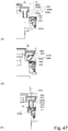
- Figure 7 illustrates a positional relation between the feeding screw 26 and the discharge opening 32d.
- Figure 8 shows a view of the feeding screw 26 and the first coupling member 29 in the process cartridge 7, as seen in the direction of the center line 61a.
- the second feeding passageway 61 is positioned such that the center line 61a of the second feeding passageway 61 passes between the center of the shaft of the residual toner feeding screw 26 and the axis center 1a of the photosensitive drum 1. That is, the rotation axis of the photosensitive drum 1 and the rotation axis of the first feeding member 26 are positioned in the opposite sides with respect to the center line 61a.
- the center line 61a is substantially the same as the rotational axis of the second coupling member 30. That is, rotation axis 1a of the photosensitive drum 1 and rotation axis of the residual toner feeding screw 26 are in the opposite sides with respect to the rotational axis (axis) of the second coupling member 30.
- the photosensitive drum 1, the residual toner feeding screw 26 and the second feeding passageway (discharging passageway) 61 can be accommodated in a small space. Therefore, an amount of the projection from an outer configuration line L ( Figure 3 ) of the cleaning frame 14 can be reduced or eliminated. Therefore, as seen in the axial direction of the photosensitive drum 1, the cleaning unit or the process cartridge can be downsized.
- the opening 61b of the second feeding passageway 61 is positioned so that it overlaps with an area which can be taken by a reverse screw portion 26e during rotation of the feeding screw 26, in a range K.
- the opening 61b is a communicating portion between the first feeding passageway 51 and the second feeding passageway 61.
- the direction of the center line 61a is substantially perpendicular to the axis of the feeding screw 26. In other words, as the feeding screw 26 is seen in the perpendicular direction, the reverse screw 26e overlaps with the opening 61b.
- the feeding force of the feeding screw 26 can smoothly feed the residual toner from the first feeding passageway 51 to the second feeding passageway 61.
- the first feeding passageway 51 and the second feeding passageway 61 overlap with each other.
- the width of the cleaning unit 13 measured in the longitudinal direction thereof can be reduced, while assuring the diameter of the feeding passageway required for the residual toner feeding.
- the process cartridge 7 can be downsized.
- the reverse screw portion 26e can be deemed as a second feeding portion of the feeding screw 26. That is, the feeding screw 26 comprises a first feeding portion (feeding screw portion 26a) which is a major part for feeding the toner, and the second feeding portion (reverse screw portion 26e) for feeding the toner in the direction opposite from that of the first feeding portion ( Figure 4 ).
- the feeding screw portion 26a of the feeding screw 26 functions to feed the toner toward the opening 61b.
- the second feeding portion (reverse screw portion 26e) is disposed downstream of the feeding screw portion 26a in the toner feeding direction of the feeding screw portion 26a.
- the reverse screw portion 26e as the second feeding portion is provided adjacent to the opening 61b, and a length of the reverse screw portion 26e is smaller than that of the first feeding portion.
- the bearing member 27 is provided with the second feeding passageway 61, as the residual toner discharging portion 40, in fluid communication with the first feeding passageway 51 and extends in the direction perpendicular to the axis of the photosensitive drum 1.
- the second feeding passageway 61 is provided with the discharge opening 32d.
- the first coupling member 29 is disposed in the second feeding passageway 61.
- the first coupling member 29 is supported by the supporting portion 28b of a coupling receptor 28 so as to be rotatable about the center line 61a.
- the first coupling member 29 is provided with a plurality of drive pins 29b which are sequentially engaged with the drive transmission blade 26g provided on the feeding screw 26. Therefore, the driving force is transmitted from the feeding screw 26 to the first coupling member 29.
- the driving rotation for the photosensitive drum 1 is converted into the rotation about an axis perpendicular to the axis of the photosensitive drum 1 (center line 61a of the second feeding passageway 61) and is transmitted to the first coupling member 29.
- the drive transmission blade 26g is a blade (helical portion) constituting the above-described reverse screw portion 26e, and the first coupling member 29 receives the driving force (rotational force) from the reverse screw portion 26e.
- Figure 9 is an exploded view illustrating the structure of the residual toner discharging portion.
- Figure 10 is a sectional view illustrating mounting of the first coupling member 29 and the second coupling member 30 to the coupling receptor 28.
- the residual toner which is the untransferred toner removed from the photosensitive drum 1 is fed to the main assembly receiving opening 80d by way of the first coupling member 29, the coupling spring 31, the second coupling member 30 and the residual toner connecting member 32.
- the residual toner connecting member 32 can be engaged with and disengaged from the main assembly receiving opening 80d.
- the first coupling member 29, the second coupling member 30, the coupling spring 31, the coupling receptor 28 and the residual toner connecting member 32 are arranged substantially on a common axis along the center line 61a.
- the first coupling member 29 and the second coupling member 30 are connected with each other by the coupling spring 31.
- the residual toner connecting member 32 is mounted so as to be movable in a direction of an arrow N ( Figure 10 ) relative to the coupling receptor 28 together with the second coupling member 30 against an urging force of the coupling spring 31.
- the residual toner connecting member 32 is movable in the direction indicated by the arrow N in Figure 10 .
- Figure 11 shows the assembled residual toner connecting member.
- the second feeding passageway 61 is a toner feeding passageway formed in the residual toner discharging portion 40.
- the residual toner discharging portion 40 comprises the coupling receptor 28, the first coupling member 29, the second coupling member 30, the coupling spring 31 and the residual toner connecting member 32.
- the first coupling member 29 is provided with a plurality of drive pins (engaging portions projections) 29b in the form of projections engageable with the feeding screw 26 for rotation.
- the drive pins 29b are substantially equidistantly arranged about the rotational axis of the first coupling member 29 substantially on a concentric circle.
- the drive pins 29b project in the axial direction of the first coupling member 29.
- the first coupling member 29 is provided with two drive claws 29c in the form of projections for transmitting the driving force to the second coupling member 30.
- the first coupling member 29 is a drive transmitting portion for transmitting the driving force (rotational force) of the feeding screw 26 to the second coupling member 30.
- the rotational axis of the first coupling member 29 crosses with the rotational axis of the feeding screw 26 (substantially perpendicular to each other).
- the first coupling member 29 changes the direction of rotation.
- the first coupling member 29 is provided in the toner feeding passageway.
- the driving claw 29c of the first coupling member 29 is fitted into the inside circumference of the cylindrical portion 28a of the coupling receptor 28 so that the first coupling member 29 is rotatably supported.
- the driving claw 29c has a partly cut-away cylindrical configuration.
- the second coupling member 30 is provided with a driving claw 30f at each of two positions to receive the rotation drive from the driving claw 29c of the first coupling member 29.
- the second coupling member 30 is provided with a recess 30h and a spring hook groove portion 30c as opposed to the driving claw 30f.
- the driving claw 30f also has a partly cut-away cylindrical configuration.
- the driving claw 30f has a substantially the same outer diameter as the driving claw 29c.
- the second coupling member 30 is inserted into the cylindrical portion 28a of the coupling receptor 28 so that the driving claw 30f is opposed to the driving claw 29c of the first coupling member 29.
- the driving claws 29c, 30f can be said to be projections by the partly-cutting-away of the cylindrical configuration, or bent plates having drive transmission surfaces.
- the outer configuration thereof is trapezoidal such that one side is inclined, and the opposite side is parallel with the rotational axis.
- the coupling spring 31 at the urging member is a twisted coil spring having a bent free-end 31a and a ring configuration 31b in the opposite direction.
- the coupling spring 31 is inserted into the second coupling member 30 in a direction of an arrow I, so that the end portion 31a is fitted in the spring hook groove 30c ( Figure 9 ).
- the circular portion 31b of the coupling spring 31 is engaged with a groove portion 29f of the first coupling member 29.
- the coupling spring 31 is expanded from the free length.
- the coupling spring 31 applies the urging force in the contracting direction.
- the first coupling member 29 and the second coupling member 30 are urged toward each other.
- a supporting portion 29d of the first coupling member 29 abuts to the supporting portion 28b of the coupling receiving portion 28.
- first coupling member 29 and the second coupling member 30 are rotatably supported on the inner surface of the cylindrical portion 28a of the coupling receptor 28 through the driving claws 29c and 30f.
- the first coupling member 29 and the second coupling member 30 are integrally rotatable by the engagement between the engaging portion 29e and the engaging portion 30g in the direction of the arrow T of the center line 61a.
- the coupling receptor 28 is mounted to the bearing member 27R by welding or bonding or the like at the welded portion 28e,in the state that the first coupling member 29, the second coupling member 30 and the coupling spring 31 are mounted thereto. By this, the leakage of the residual toner to the outside is reduced.
- the residual toner connecting member 32 is provided with a supporting portion 32a to be supported by the second coupling member 30 in the axial direction.
- the coupling receptor 28 is provided with a rotation stopper rib 28d for positioning the residual toner connecting member 32 in the rotational direction.
- the residual toner connecting member 32 is provided with a recessed groove 32i for positioning in the rotational direction, at a part of the circumference.
- Second coupling member 30 is provided with a compression claw 30e at diametrically opposite positions.
- the coupling receptor 28 is provided with the first coupling member 29, the second coupling member 30 and the coupling spring 31.
- the residual toner connecting member 32 is coaxially fitted around the coupling receptor 28 in the direction indicated by the arrow I.
- the rotation stopper rib 28d of the coupling receptor 28 is engaged with the groove 32i of the residual toner connecting member 32 ( Figure 9 ). In this manner, the relative position between the coupling receptor 28 and the residual toner connecting member 32 with respect to the rotational moving direction about an axis 61a is limited.
- the supporting portion 32a enters by deforming radially inwardly the compression claw 30e of the second coupling member 30 supported by the coupling receptor 28.
- the supporting portion 32a rides over the compression claw 30e of the second coupling member 30, and the residual toner connecting member 32 is supported by the compression claw 30e of the second coupling member 30 by the supporting portion 32a in the vertical direction (part (b) of Figure 11 ).
- Figure 12 is a schematic view illustrating the driving connection structure for the residual toner discharging portion 40.
- the feeding screw 26 is provided in the first feeding passageway 51.
- the supporting portions 26b, 26c provided at the opposite ends of the feeding screw 26 are rotatably engaged with holes 27La, 27Ra provided in bearing members 27L, 27R, respectively.
- the photosensitive drum 1 is also rotatably supported by the bearing member 27. As shown in Figure 12 , one end portion of the photosensitive drum 1 is provided with a coupling portion 1c for receiving a driving force from the main assembly 100. The other end thereof is provided with a photosensitive drum gear 1b for transmitting the driving force to the residual toner feeding screw 26, as will be described hereinafter.
- the cleaning unit 13 is provided at one axial end of the photosensitive drum 1 with the photosensitive drum gear 1b, an idler gear 52 rotatably supported by the bearing member 27 and a feeding screw gear 53.
- the feeding screw gear 53 is engaged with the feeding screw 26, for driving force transmission.
- the rotational force is transmitted from a main assembly drum input coupling 81 ( Figure 23 ) of the image forming apparatus 100 to the coupling portion 1c at one end of the cleaning unit 13.
- the transmitted rotational driving force is in turn transmitted from the photosensitive drum 1 to the feeding screw 26 by the sequential engagement of the photosensitive drum gear 1b, the idler gear 52 and the feeding screw gear 53.
- the residual toner accommodated in the residual toner accommodation chamber 14a is fed in the direction of the arrow H (axial direction of the feeding screw 26) by the feeding screw portion 26a by the rotation of the feeding screw 26 in the direction of the arrow G.
- the reverse screw portion 26e is provided at the downstream side end portion of the feeding screw 26 with respect to the residual toner feeding direction.
- the reverse screw portion 26e is provided with a drive transmission blade 26g in the form of a screw.
- the feeding screw 26 receives the driving force by the rotation of the photosensitive drum 1.
- the feeding screw 26 may be driven in interrelation with the rotation of the developing roller 17.
- Figure 29 shows such a modified example.
- Figure 29 illustrates an example of a structure with which the feeding screw 26 receives the driving force from the developing roller 17.
- one end of the toner supplying roller 20 is provided with a coupling portion 57 for receiving the driving force from the main assembly 100.
- the other end thereof is provided with a toner supplying roller gear 58 for transmitting the driving force to the residual toner feeding screw 26, as will be described hereinafter.
- the developing device 4 includes the toner supplying roller gear 58 and a developing roller gear 59.
- a drum bearing 27 supports the idler gear 52 and the feeding screw gear 53.
- the feeding screw gear 53 is engaged with the feeding screw 26, for driving force transmission.
- the rotational force is transmitted from a main assembly development input coupling 82 of the image forming apparatus 100 to the coupling portion 57 provided at the end of the developing device 4.
- the transmitted rotational force is transmitted from the toner supplying roller 20 to the feeding screw 26 through the developing roller 17 by the sequential engagement of the toner supplying roller gear 58, the developing roller gear 59, the idler gear 52 and the feeding screw gear 53.
- the residual toner accommodated in the residual toner accommodation chamber 14a is fed in the direction of the arrow H by the feeding screw portion 26a by the rotation of the feeding screw 26 in the direction of the arrow G.
- the developing roller gear 59, the developing roller gear 59, the idler gear 52, the feeding screw gear 53, the feeding screw 26 and the first coupling 29 constitute the drive transmitting portion for transmitting the driving force from the toner supplying roller 20 to the second coupling member 30.
- Figure 13 is a sectional view illustrating the position of the residual toner feeding in the main assembly 100.
- a main assembly feeding portion 80 is provided in the front side of the rear side plate 98 provided with the mounting direction abutting portion, with respect to the mounting direction of the process cartridge 7. Therefore, it is not required that a cut-away portion for the residual toner discharging portion or the like of the process cartridge 7, as compared with the case in which the main assembly feeding portion 80 is provided in the rear side of the rear side plate 98 with respect to the mounting direction (arrow J). Therefore, as compared with the case in which the cut-away portion is provided, strength of the rear side plate 98 is assured.
- the second feeding passageway 80b is disposed right below the first feeding passageway 80a.
- the main assembly second feeding passageway 80b extends over the process cartridges 7Y, 7M, 7C and 7K. Therefore, in the case that the main assembly feeding passageway 2 is disposed right below the main assembly feeding passageway 1, the result is that it enters toward the process cartridge 7 in the front side with respect to the mounting direction.
- the main assembly second feeding passageway 80b is desirably placed at a position as close as possible to the rear side plate as shown in Figure 13 .
- the center lines of the first main assembly feeding passageway 80a and the second main assembly feeding passageway 80b are offset in the longitudinal direction, as depicted by AB in the Figure.
- the first coupling member 29 and the second coupling member 30 are connected with each other by the urging force provided by the coupling spring 31 in the direction of the arrow I. Therefore, the residual toner connecting member 32 supported by the second coupling member 30 is movable against the urging force of the coupling spring 31 in the direction of the arrow I within the range in which it is engageable with the cylindrical portion 28a of the coupling receptor 28.
- the residual toner connecting member 32 is movable together with the second coupling member 30 relative to the process cartridge 7 in the direction of the arrow N (part (b) of Figure 1 and part (b) of Figure 10 ).
- the driving claw 29c of the first coupling member 29 and the driving claw 30f of the second coupling member 30 are supported so as to be engageable in the rotational direction T in the inside circumference of the cylindrical portion 28 of the coupling receptor 28.
- engaging portions 29e, 30g have projecting configurations extending in the axial direction. Therefore, even in the state that the second coupling member 30 has moved in the direction of the arrow N relative to the first coupling member 29 (part (b) of Figure 1 and part (b) of Figure 10 ), the engaging portions 29e, 30g are capable of transmitting the driving force in the rotational direction T.
- the residual toner connecting member 32 when the cartridge is set in the main assembly and is operating for the printing operation, the residual toner connecting member 32 is in the state that the second coupling member 30 has moved relative to the first coupling member 29 in the direction of the arrow N (drive transmission position).
- the residual toner discharging portion 32d at the free end of the residual toner connecting member 32 suppresses the leakage of the toner by entering the receiving opening 80d of the main assembly 100 by a predetermined amount. The details of feeding of the residual toner at this time will be described hereinafter.
- the first coupling member 29 and the second coupling member 30 of the residual toner discharging portion of the process cartridge 7 are engaged with each other to rotate, in a main assembly connection state (drive connecting position, part (b) of Figure 1 ) and main assembly retraction state (retracted position, part (a) of Figure 1 ). Therefore, even in the free state of the process cartridge 7, the engagement between the first coupling member and the second coupling member can be checked by rotating the photosensitive drum 1.
- Figure 8 illustrates the engagement between the drive transmission blade 26g and the first coupling member 29.
- the drive pins 29b are in the form of cylindrical projecting configurations arranged at equidistant angular positions about the axis of the coupling 29.
- six drive pins 29b are arranged at 60° intervals, and each have 1.8 mm of diameter.
- a line (X) perpendicular to the axial direction of the feeding screw 26 passing through the center of the first coupling member 29 is in the center.
- the two drive pins 29b are at the same angular positions Y in the opposite side with respect to the line X.
- the drive pin 29b1 and the drive pin 29b2 are most distant from each other in the axial direction of the feeding screw 26 (part (a) of Figure 8 ).
- the drive transmission blade 26 rotates the drive pin 29b1 in the direction T in the downstream side of the drive pin 29b with respect to the rotational moving direction T.
- the first coupling member 29 temporarily stops until the drive transmission pin 29b2 which is upstream of the drive transmission pin 29b1 in the rotational moving direction is brought into contact to the drive transmission blade 26g.
- the drive transmission blade 26g moving in the direction of the arrow S contacts to the drive transmission pin 29b.
- the first coupling member 29 continues to be rotated by the rotation of the feeding screw 26.
- the pitch of the drive transmission blade 26g is larger than a distance Z between the drive pins 29g as measured in the axial direction.
- the drive pins 29b can be continuously pushed by the engagement between the drive transmission blade 26g and the drive pins 29b.
- the drive pin 29b has a cylindrical configuration, but another configuration is usable if the drive transmission is possible.
- a blade configuration corresponding to the feeding screw 26 and a projecting configuration such as a gear or the like can provide the same effects.
- Figure 14 schematically shows a modified example of the drive pin 29b.
- a drive pin 129b of the first coupling member 129 is integrally provided with a toner guide the surface 129f.
- the toner guiding surface 129f provided on the drive pin 129 is disposed outside the hole portion 129a.
- the toner guiding surface 129f provides a surface connecting an outer circumference side 129g of the guiding surface and an inner circumference side 129h of the guiding surface.
- the outer circumference side 129g extends toward the downstream side with respect to the rotational moving direction T (clockwise direction) of the first coupling member 129, and the inner circumference side 129h is in the upstream side with respect to the rotational moving direction T. That is, with the rotation of the first coupling member 129, the toner guiding surface 129f produces a force for moving the toner inwardly.
- the toner guiding surface 129f functions as a toner feeding portion for feeding the toner.
- the hole portion 129a is an opening for permitting the toner toward the second feeding passageway 61.
- Figure 1 is a sectional view illustrating a connecting method between a residual toner discharging portion 23d and the main assembly residual toner receiving opening 80d.
- Figure 16 is a schematic view illustrating a connecting method of a residual toner connecting portion 32.
- the main assembly 100 comprises the residual toner receiving opening 80d for receiving the discharging toner from the process cartridge 7.
- the residual toner receiving opening 80d is provided with an elastic sealing member 47 such as rubber sponge.
- an elastic sealing member 47 such as rubber sponge.
- the main assembly receiving opening sealing member 47 has an inner diameter ⁇ 10.4 mm, and the residual toner connecting member 32 has a diameter of ⁇ 11.4 mm.
- the main assembly receiving opening sealing member 47 is provided with a plurality of slits 47a to accept the residual toner connecting member 32 easily.
- the residual toner connecting member 32 is provided with a tapered configuration 32k to accommodate a positional deviation between the residual toner connecting member 32 and the residual toner receiving opening 80d in the axial direction.
- the residual toner connecting members 32 is provided with a rib configuration 321, by which when it is mounted to the residual toner receiving opening 80d, the gaps is closed.
- the main assembly residual toner transportation portion 80 is provided with the first main assembly feeding passageways 80a having the residual toner receiving opening 80d and the second feeding passageways 80b for feeding the residual toner into the residual toner container 86 of the main assembly 100.
- the first main assembly feeding passageways 80a is provided with a spring stopper 43 adjacent to the receiving port.
- the vibrating member 44 having an elastic force provided in the first main assembly feeding passageway 80a is supported by the spring stopper 43 by abutment thereto at the spring portion 44a.
- the residual toner connecting member 32 is urged in the direction of the arrow N by the arm 42 and enters the residual toner receiving opening 80d. With this intrusion (entry), against the reaction force of the vibration member 44, the residual toner connecting member 32 presses the vibration member 44 in the direction of the arrow N (the direction of entering the residual toner connection port).
- the vibration member 44 abuts against the second coupling member 30 in the residual toner connecting member 32 with an urging force.
- the abutted second coupling member 30 rotates in interrelation with the rotation of the photosensitive drum 1.
- the abutment portion 44b of the vibration member 44 abuts against the recess 30h of the second coupling member 30, and the vibration member 44 moves in the vertical direction. Details will be described hereinafter.
- the spring coupling 44 is a compression spring having a wire diameter of ⁇ 0.6 mm and an inner diameter ⁇ 12.3 mm, approximately.
- the spring coupling 44 provides the urging forces of approx. 33gf in the state of abutting to the spring stopper 43 (uncoupled state) and approx. 50gf in the connection state of the second coupling member 30.
- the driving force is transmitted to the drum gear 1b, the idler gear 52, the feeding screw gear 53, and the feeding screw 26. Furthermore, the driving force is transmitted from the feeding screw 26 in the order of the first coupling member 29 and the second coupling member 30. In this manner, the residual toner is discharged from the process cartridge 7 to the main assembly 100. Furthermore, the vibration member 44 of the apparatus main assembly 100 is vibrated by the rotational driving force from the second coupling member 30. The residual toner fed to the vibration member 44 is loosened by the vibration of the vibration member 44 in the main assembly feeding portion 80 and it is fed to the main assembly feeding screw 85 and fed to the residual toner box 86 by the carrying force of the main assembly feeding screw 85.
- the residual toner receives a feeding force in the direction opposite to the direction of the arrow H by the reverse screw portion 26e. Therefore, the residual toner is fed in the direction of the arrow H and the residual toner fed in the opposite direction by the reverse screw portion 26e collide to each other at the position between the feeding screw portion 26a and the reverse screw portion 26e and stagnates there.
- the residual toner accommodating portion 14a is provided between the feeding screw 26 and the photosensitive drum 1.
- the first coupling member 29 is please in the residual toner accommodating portion 14a.
- the stagnating toner flows in the axial center direction of the first coupling member 29. And, it is fed to a hole 29a (part (a) of Figure 7 , Figure 9 ) provided on the rotational axis of the first coupling member 29.
- the hole 29a is an opening for allowing movement of the toner.
- the toner which has passed through this hole 29a moves to the second feeding passageway 61.
- the residual toner is discharged through a discharge portion 32d provided at a lower portion of the first coupling member 29 which will be described hereinafter.
- the residual toner flowing in the direction of the arrow H receives the feeding force in the opposite direction by the reverse screw portion 26e.
- the residual toner is prevented from entering a contacting position V between the drive transmission blade 26g and the drive pin 29b.
- the contact portion V between drive transmission blade 26g and the drive pin 29b is not easily influenced by the residual toner. Therefore, the stability of the drive transmission is improved.
- the residual toner is fed by the residual toner screw 26 along the axial direction of the photosensitive drum 1 toward one end portion side of the cartridge (arrow H in Figure 4 ).
- the fed residual toner particles collide at the position between the feeding screw portion 26a and the reverse screw portion 26e to be fed into the hole portion 29a of the first coupling member 29.
- the first coupling member 29 is rotated in the direction of the arrow T.
- the first coupling member 29 is provided with the hole portion (opening) 29a.
- the residual toner having passed through the hole portion 29a flows into the inner diameter portion of the coupling spring 31 of the first coupling member 29.
- the residual toner flows into the hole portion 30a of the second coupling member 30 engaged with the first coupling member 29.
- the driving force is transmitted from the engaging portion 29e to the engaging portion 30g of the second coupling member 30.
- the second coupling member 30 and the coupling spring 31 rotate integrally with each other.
- the coupling spring 31 ( Figure 9 ) is wound in such a direction that the residual toner is fed in the direction of the arrow N in Figures 1 , 7 when it rotates together with the first coupling member 29 and the second coupling member 30. For this reason, the residual toner is positively fed in the direction of the arrow N in addition to the free falling in the direction of the arrow N.
- the coupling spring 31 is effective to loosen the residual toner by the rotation in the second feeding passageway 61. Therefore, the feeding (movement) of the residual toner is made smoother. That is, the urging member (coupling spring 31) urging the second coupling member 30 is provided with a feeding portion for feeding the toner and a stirring portion effective to stir the toner as well.
- the residual toner having passed through the coupling spring 31 and the hole portion 30a of the second coupling member 30 is discharged to the residual toner discharging portion 32d of the residual toner connecting member 32 supported in the direction of the arrow N by the second coupling member 30.
- the foregoing is the discharging of the residual toner in the process cartridge 7.
- the residual toner discharged from the residual toner discharging portion 32d enters the feeding passageway 80b from the residual toner receiving opening 80d provided in the main assembly of the image forming apparatus 100 below the residual toner discharging portion 32d. Then, the residual toner in the feeding passageway 80b is discharged into the residual toner box (main assembly side toner accommodating portion) 86 by the main assembly feeding screw 85 as the feeding member in the second feeding portion 80b which is the main feeding passageway.
- a main assembly second feeding passageway 80b which is substantially perpendicular to the lower end of the main assembly first feeding passageway 80d is connected by a connecting portion 80f.
- the residual toner fed in the falling direction is fed to the main assembly second feeding unit 80b.
- the first feeding passageway 80a and the second feeding passageway 80b are arranged so as to shift the central axis in a substantially orthogonal position and clogging of the residual toner at the connecting portion 80f is likely to occur.
- the vibration member 44 vibrates by the action imparted from the process cartridge 7 so that the residual toner is loosened, and the toner clogging at the connecting portion 80f is prevented, and therefore, the residual toner is conveyed stably.
- the residual toner fed to the main assembly second feeding portion 80d is fed in the direction of the arrow R upon receiving the feeding force of the main assembly feeding screw 85 as the feeding member shown in Figure 5 , and is fed to the residual toner box 86 and collected therein.
- the second main assembly feeding passageway 80b extends over the respective color process cartridges.
- the residual toner box 86 is in the form of an exchangeable box.
- the inner diameter of the hole portions of the first coupling member 29 and the second coupling member 30 and the coupling spring 31 are selected such that the residual toner is stably discharged.
- the residual toner connecting member 32 is mounted to the outside of the coupling receptor 28 provided with the first coupling member 29 and the second coupling member 30 therein. Therefore, the outer diameter of the cylindrical shape 28a of the coupling receptor 28 is approx. ⁇ 9.2 mm, and the outer diameter of the residual toner connecting member 32 is approx. ⁇ 11.4 mm. As described hereinbefore, the residual toner connecting member 32 enters the residual toner receiving opening 80d of the main assembly 100. In this embodiment, the inner diameter of the residual toner receiving opening 80d is ⁇ 10.4 mm, and the residual toner connecting member 32 enters while compressing the main assembly receiving opening sealing member 47 to close the gap.
- the hole portion 29a of the first coupling member 29 and the hole portion 30a of the second coupling member 30 have the inner diameters of 05.4 mm through which the residual toner passes.
- the inner diameter of the coupling spring 31 is about 4.5 mm.
- the residual toner discharging portion 32 has about ⁇ 8.4 mm, and the main assembly receiving opening 80d is about ⁇ 10.4 mm as described above.
- the diameter of the feeding passageway increases toward the downstream side of the residual toner transportation. By doing so, the toner clogging in the residual toner transportation passageway from the process cartridge 7 to the main assembly feeding portion 80 is prevented, thus stabilizing the toner discharging.
- the arrow N direction which is the residual toner feeding direction is inclined relative to the free falling direction of the residual toner by approx. 19° inclination.
- the residual toner connecting member 32 and the second coupling member 30 are in the positions having moved in the direction of the arrow N against the urging force of the coupling spring 31, that is, they are in the drive transmission position.
- first coupling member 29 and the second coupling member 30 are engageable with each other in the rotational moving direction in the engaging portion 29e, 30g even in the state that they have moved in the direction of the arrow N which is the axial direction.
- the residual toner fed into the hole portion 29a of the first coupling member 29 is further fed along the arrow N direction through the second coupling member 30, the coupling spring 31 and the residual toner connecting member 32.
- the residual toner connecting member 32 is provided with the projecting configuration supporting portion 32a supported by the above-described second coupling member.
- the residual toner is fed to the residual toner discharge opening 32 while accumulating on the projecting configuration supporting portion 32a.
- the residual toner connecting member 32 and the second coupling member 30 move toward the first coupling member 29 with the residual toner accumulated in the U -shaped portion of the residual toner discharging portion 32.
- the accumulated residual toner in U portion is pushed out in the direction of the arrow N to a tapered portion 28f of a cylindrical free end portion 28c of the coupling receptor 28.
- the residual toner flows through a plurality of slit portions 32j provided in the supporting portion 32a of the residual toner discharging portion 32 shown in Figure 11 to be fed into the residual toner discharging portion 32d.
- the residual toner clogging can be prevented when the residual toner connecting member 32 and the second coupling member 30 returns to the positioning determining position from the position away from the first coupling member 29.
- Figure 17 is a perspective view illustrating a supporting structure for the shutter.
- the residual toner connecting member 32 which is the above-described residual toner discharge opening is provided.
- the residual toner connecting member 32 is provided with guide portions 32b, 32c in the form of projections projecting in the axial direction.
- the shutter 34 is provided with groove portions 34a, 34b at the opposite end portions with respect to the direction along the cross-section plane.
- Shutter 34 is guided by the projecting configuration guide portions 32b, 32c at the groove portions 34a, 34b so as to be movable in the mounting direction (arrow J direction), and seals the residual toner discharging portion 32d.
- the shutter 34 is provided with an elastic sealing member 35 for sealing the residual toner discharging portion 32d.
- the shutter 34 is supported such that the elastic sealing member 35 is compressed by the discharge opening 32d. Therefore, as shown in part (a) of Figure 17 , the discharge opening 32d of the residual toner connecting member 32 is closed by the elastic sealing member 35 without gap, thus sealing against the residual toner.
- the shutter 34 is urged toward the rear side in the mounting direction (arrow J direction) by the urging member 36 provided on the cleaning frame 14.
- a discharge opening abutting portion 34d of the shutter 34 is abutted to an abutting portion 32e of the residual toner connecting portion 32 by the urging member 36. In this manner, the shutter 34 is positioned and supported by the residual toner connecting member 32 on the process cartridge 7.
- the cleaning frame 14 is provided with a shutter guide portion 14b supporting the shutter 34 movably in the mounting direction and extending in the mounting direction (arrow J direction) at the same position as the guide portion 32b of the residual toner connecting member 32 with respect to a plane of cross-section.
- the shutter engaging portions 34a, 34b of the shutter 34 is partly supported by the shutter guide portion 14b of the cleaning frame 14 in abutment to the abutting portion 32e of the residual toner connecting member 32.
- the shutter 34 is supported by residual toner connecting member 32 and the cleaning frame 14.
- the shutter 34 moves in the direction opposite to the inserting direction (opposite to the arrow J direction) in the process cartridge 7 in the mounting to the main assembly 100.
- the shutter 34 is capable of opening and closing the opening (discharge opening 32d) for discharging the residual toner.
- the shutter 34 is completely disengaged from the shutter guide portions 32b, 32c of the residual toner connecting member 32 by the movement in the direction opposite to the arrow J. Then, the shutter 34 is engaged with and is supported by only the guide portion 14b of the cleaning frame 14. Therefore, in the state that the cartridge is mounted in the main assembly 100, the shutter 34 does not obstruct the movement of the residual toner connecting member 32 in the direction along a plane of cross-section (arrow N direction).
- the shutter 34 is a locking member for locking the residual toner connecting member 32 to prevent the movement in the direction of the arrow N, as well.
- Figure 19 is a front view in the state that the front door 91 of the main assembly 100 is open.
- Figure 20 is a sectional view illustrating a structure of a lower guide 94 of the cartridge.
- Figure 21 is a schematic view illustrating a mounting process of the process cartridge 7 to the main assembly 100.
- the mounting operation of the process cartridge 7 to the main assembly of the image forming apparatus 100 will first be described. As shown in Figure 19 , the process cartridge 7 is mountable to and dismountable from the main assembly 100 in the direction of the arrow J.
- the residual toner transportation portion 40 is provided in the rear side with respect to the mounting direction of the process cartridge 7.
- the residual toner produced during the image forming operation is fed from the process cartridge 7 to the receiving opening (unshown) of the main assembly 100.
- the process cartridge 7 is inserted in the direction of the arrow J after the front door 91 of the main assembly of the image forming apparatus 100 is opened. Thereafter, the process cartridge 7 is inserted in the direction of the arrow J to the extent that it abuts to the rear side plate (unshown) in the rear side of the main assembly, thus completing the inserting operation. Thereafter, the front door 91 of the main assembly 100 is closed, by which the process cartridge 7 is positioned in place in the main assembly. And, the residual toner connecting portion (unshown) is connected with the main assembly 100, by which the mounting operation is completed. The details of the mounting operation will be described step-by-step.
- the process cartridge 7 is provided with lower guides 7a, 7b to be guided by the main assembly 100 during the mounting operation at the opposite end portions with respect to the longitudinal direction of the cartridge.
- the process cartridge 7 is provided with upper guides 7c, 7d to be guided by the main assembly 100 during the mounting operation at the opposite end portions with respect to the longitudinal direction.
- the main assembly 100 is provided with a front cover 92 ( Figure 19 ) for restricting the sectional area of the process cartridge 7 at the entrance.
- a cartridge mounting portion 93 of the main assembly 100 there are provided a lower guide 94 for guiding the lower portion of the process cartridge 7 and an upper guide 95 for guiding the upper portion of the process cartridge 7.
- the lower guide 94 is provided with pressing blocks 96 and 97 to press the process cartridge 7 substantially in the upward direction which is substantially perpendicular to the mounting direction.
- the pressing block 96, 97 are provided at each of the front side and the rear side with the respect to the mounting direction of the cartridge.
- the cartridge rides on the lower guide 94 in accordance with the movement of the cartridge toward the rear side in the mounting direction J.
- the process cartridge 7 can be inserted without contact to the intermediary transfer belt 5 disposed in the upper side.
- the process cartridge 7 is inserted into the cartridge mounting portion 93 while being guided by a lower guide 91a of the front door.
- the process cartridge 7 having moved to the mounting portion 93 is restricted in the position thereof by a rough mounting guide portion 92a of the front cover 92 shown in Figure 19 in the plane perpendicular to the mounting direction.
- the process cartridge 7 is mounted to the cartridge mounting portion 93 with the regulated attitude in the direction along a plane perpendicular to the mounting direction.
- the process cartridge 7 is sufficiently away from the intermediary transfer belt 5.
- the projecting configuration of the lower guide 7a is engaged with the recessed configuration of the lower guide 94 so that the cartridge is guided thereby.
- the process cartridge 7 is guided so that the projecting configuration of the guide portion 7c is engaged with the recessed configuration of the upper guide 95, while being guided by the lower guide 7a.
- the process cartridge 7 moves in the direction of the arrow J on the lower guide 94 while being restricted by the lower guide 7a and the upper guide 7c in the directions perpendicular to the mounting direction.
- the lower guide 94 rises upwardly in accordance with the insertion toward the rear side by the configuration of the lower guide 94. Therefore, the process cartridge 7 is inserted into the main assembly 100 while being raised by the engagement with the lower guide 94.
- the lower guide 7a rise on the inclined portion 94a of the lower guide 94 in the direction perpendicular to the mounting direction. Therefore, with the insertion of the process cartridge 7 in the mounting direction (arrow J direction), the lower guide 7b rides on the lower guide 91a of the front door. Thereafter, with the continuing insertion of the cartridge, the lower guide 7b rise on the lower guide 94 and the pressing block 96 in the order named, similarly to the lower guide 7a.
- Figure 22 is a perspective view illustrating the structure of the rear side of the process cartridge 7 with respect to the mounting direction.
- the process cartridge 7 is provided with a shaft 7g for positioning the process cartridge 7 relative to the main assembly 100 in the direction perpendicular to the mounting direction, the shaft 7g extending toward the rear side in the mounting direction.
- the process cartridge 7 is provided in the rear side with respect to the mounting direction with an upper guide abutting portion 7e and a vertical abutting portion 7f for limiting the position of the process cartridge 7 substantially in the vertical direction during the inserting operation.
- the process cartridge 7 is provided with a retention groove 7h for preventing disengagement of the process cartridge 7 from the main assembly 100.
- the retention groove 7h is in the form of a recessed configuration provided in the rear side of the process cartridge with respect to the mounting direction.
- the photosensitive drum 1 of the process cartridge 7 is provided with a coupling portion 1c as a drive inputting portion for receiving a driving force from the main assembly 100 in the rear side with respect to the mounting direction. Furthermore, the toner supplying roller 20 ( Figure 3 ) is provided with the coupling portion 57 as the input portion for receiving a driving force from the main assembly 100.
- Figure 23 is a perspective view illustrating the rear side structure of the main assembly 100, with respect to the mounting direction of the process cartridge 7. As shown in Figure 23 , the main assembly 100 is provided on the rear side plate 98 with an abutting portion 98a as a longitudinal abutting portion at the time of mounting the process cartridge 7.
- the rear side plate 98 is provided with V-shaped groove portion 98b and a positioning elongate hole portion 98c for positioning the process cartridge 7 in the direction perpendicular to the mounting direction, and they are provided at an upper and lower parts, respectively.
- a drum drive input coupling 81 for inputting the driving force to the photosensitive drum 1 is provided in a rear side of the rear side plate 98 with respect to the mounting direction.
- the drum drive input coupling 81 is supported so as to be movable in the direction of the arrow J by the urging member (unshown).
- a development drive input coupling 82 for inputting a driving force to the coupling portion 57.
- the development drive input coupling 82 receives the driving force from the driving source (unshown) of the main assembly 100 and rotates.
- the voltage application member 83 for applying a voltage to the process cartridge 7.
- the voltage application member 83 includes an elastic member such as a compression coil spring extending in the direction opposite to the direction of the arrow J.
- a recording contact 84 for recording in a chip 33 as the storing element of the process cartridge 7.
- the recording contact 84 includes elastic projected portions 84a and 84b projecting in the direction opposite to the mounting direction and is supported by the rear side plate 98 so as to be movable substantially in the vertical direction.
- the upper guide 95 of the main assembly 100 is provided with an upper guiding rail abutting portion 95a for being abutted by the upper guide abutting portion 7e of the process cartridge 7 to support it.
- the rear side plate 98 is provided with a limiting portion 98d for being contacted by the vertical abutting portion 7f of the process cartridge 7 to contact and support it.
- the rear side plate 98 supports the arm 42 for engaging with the residual toner connecting member in a state in which it is rotatable within a predetermined angular range about the arm rotation axis 42c. That is, the arm rotation axis 42c of the arm 42 is supported at both ends thereof by arm support portions 98e, 98f ( Figure 26 ) of the rear side plate 98.
- the arm supporting portion 98e has the same shape as the arm supporting portion 98f.
- the arm 42 is supported and positioned in the rotational moving direction by the lower guide 94 using a link mechanism (unshown).
- the process cartridge 7 is inserted toward the rear side of the main assembly in the state that the upper guide 7c and the lower guides 7a, 7b are supported by the upper guide 95 and the lower guide 94, as shown in part (c) of Figure 21 .
- the lower guide 7a of the process cartridge 7 rides on the tapered portion 97a of the pressing block 97 provided on the lower guide 94.
- the positioning shaft 7j of the process cartridge 7 has passed by the intermediary transfer belt 5 in the mounting direction. Therefore, the process cartridge 7 can be mounted to the main assembly 100 without the positioning shaft 7j extending upwardly contacting the intermediary transfer belt 5.
- the process cartridge 7 is supported at two positions, namely a front side portion by the lower guide 94 and a rear side portion where it is ridden. Therefore, as shown in part (d) of Figure 21 , the process cartridge 7 is being mounted with the rear side thereof lifted by slanting (approx. 0.6°), in the main assembly 100.
- the process cartridge 7 riding on the pressing block 97 receives an upward urging force from the pressing block 97.
- the upper guide abutting portion 7e abuts to an abutting portion 95a of the upper guide 95.
- Figure 24 is a schematic view illustrating the movement of the process cartridge 7 up to the completion of the insertion to the rear side of the main assembly.
- the process cartridge 7 is inserted in the state that the upper guide abutting portion 7e thereof is in abutment to the contact surface 95a of the upper guide 95.
- the process cartridge 7 moves until the vertical abutting portion 7f abutted to the upper part limiting portion 98d of the main assembly rear side plate 98.
- the upper guide abutting portion 7e enters a hole portion 95b provided in the rear side of the upper guide 95 with respect to the mounting direction, so that it is supported only in the direction perpendicular to the mounting direction (left-right direction).
- the shaft 7g of the process cartridge 7 is inserted into the elongate hole portion 98c of the rear side plate 98 of the main assembly 100.
- arm contact portions 32f and 32g which is a projected wall portion of the residual toner connecting member 32 is inserted below the contact portions 42a, 42b of the arm 42 supported by the rear side plate 98 (part (c) of Figure 24 ).
- the free ends of the contact portions 42a, 42b of the arm 42 is provided with tapers 42e, 42f, respectively, so that the arm contact portions 32f, 32g of the residual toner connecting member 32 are assuredly introduced.
- the arm 42 and the residual toner connecting member 32 are spaced from each other.
- the development coupling 37 starts to engage with the main assembly development input coupling 82.
- the vertical abutting portion 7f is disengaged from the abutting portion 98d and is raised upwardly by the urging force of the pressing block 97.
- the shaft 7j of the positioning is brought into the abutment to V-shaped groove portion 98b in the upward direction.
- the contact portion 7i ( Figure 22 ) of the process cartridge 7 abuts to the voltage application member 83 of elastic electroconductive material.
- the recording contact 84 of the main assembly 100 is brought into contact to the chip 33 as the storing element of the process cartridge 7.
- drum coupling 1c of the process cartridge 7 contact to the drum input coupling 81 of the main assembly 100 to push it out in the direction of the arrow J against the force of the urging member (unshown) of the drum input coupling.
- the lower guide 94 has such a configuration that with the insertion of the cartridge, it rises. Therefore, as shown in part (d) of Figure 21 , in the state of completion of insertion of the process cartridge 7 (abutted state), the process cartridge 7 is inclined with the rear side with respect to the mounting direction being higher (approx. 0.6°).
- Figure 18 is a schematic view illustrating the movement of the shutter 34 shutter 34 at the time of mounting to the main assembly. As shown in part (a) of Figure 24 , when the cartridge further moves in the state that the upper guide abutting portion 7e abuts to the abutting portion 95a of the upper guide 95, the shutter 34 passes above the shutter contact portion 43a of the main assembly 100 as shown in Figure 18 .
- the lower portion of the shutter 34 is provided with a projected main assembly contact portion 34c.
- the main assembly contact portion 34c is abutted by the shutter contact portion 43a.
- the shutter 34 moves relatively in the direction opposite to the mounting direction in the process cartridge 7 against the urging force of the shutter urging member 36 provided in the cleaning frame.
- the residual toner discharging portion 32d is completely opened as shown in) Figure 18 , by which the relative movement in the process cartridge 7 is completed.
- the main assembly contact portion 34c contacting the shutter contact portion 43a, the shutter 34 is moved toward the front side (arrow J) in the process cartridge 7 in accordance with the mounting operation to the main assembly 100.
- the main assembly contact portion 34c is disposed upstream of the residual toner discharge opening 32d with respect to the mounting direction. Therefore, when the shutter 34 starts to be moved by the shutter contact portion 43a in the process cartridge, the spring stopper 43 having the shutter contact portion 34 is present in a part of the region below the residual toner shutter 34.
- the process cartridge 7 when the process cartridge 7 is mounted in the state that the residual toner is in the second feeding passageway 61, the removed toner flows through the residual toner discharge opening 32d, at the time of the shutter 34 starting to be apart from the discharge opening 32d. At this time, the residual toner falls downward to the spring stopper 43.
- the spring stopper 43 is provided with falling prevention wall 43b for preventing the residual toner having fallen down from entering the main assembly 100. By this, the scattering of the residual toner in the main assembly 100 is reduced.
- the image forming apparatus is provided with a space for accommodating the cartridge.
- the user can access the space (accommodating portion) for accommodating the cartridge, by opening the front door 91 which is a part of the outer casing of the image forming apparatus.
- the process cartridge 7 receives the upward urging force from the pressing blocks 96 and 97.
- the urging force with which the rear side shaft 7j of the process cartridge 7 abuts to the V-shaped groove portion 98b which provides the abutment of the process cartridge 7 of the with respect to the direction perpendicular to the mounting direction.
- the front side abutment shaft 7k is abutted to the V-shaped groove portion 99a which is the abutment of the front side plate 99 with respect to the direction perpendicular to the mounting direction (part (e) of Figure 21 ).
- the process cartridge 7 is positioned relative to the main assembly 100 by the V-shaped groove portion 98b, the elongate hole portion 98c and the V-shaped groove portion 99a with respect to the direction perpendicular to the mounting direction.
- the link mechanism By further closing the main assembly front door 91, the link mechanism (unshown) move the drum drive input coupling 81 to the engageable position in the process cartridge 7 side.
- the raising retaining portion 46 enters the groove configuration of the retaining portion 7h of the process cartridge 7. By this, the movement of the process cartridge 7 toward the front side with respect to the mounting direction is limited.
- Figure 16 is a sectional view illustrating the operation of the residual toner connecting member in the opening and closing of the front door.
- the arm 42 rotatable by the link mechanism (unshown) in interrelation with the main assembly front door 91 is provided.
- the residual toner connecting member 32 of the process cartridge 7 is provided with the arm contact portions 32f, 32g contactable to the arm of the main assembly 100, the arm contact portions 32f, 32g projecting in the direction perpendicular to the mounting direction.
- the arm contact portions 32f, 32g are disposed below the contact portions 42a, 42b in the state that the process cartridge 7 is in abutment to the rear side plate 98 of the main assembly 100.
- the contact portions 42a, 42b of the arm 42 are overlapped with the arm contact portions 32f, 32g of the residual toner connecting member 32 by approx.4 mm in the mounting direction.
- the arm 42 is rotatable about an axis of the arm rotation shaft 42c rotatably supported by the supporting holes 98e, 98f of the rear side plate 98.
- the arm 42 is rotated in the direction of the arrow M by approx. 42° about the axis of the arm rotation shaft 42c by a link mechanism (unshown) connected with the cartridge lower guide 94.
- the arm 42 With the rotating operation of the arm 42, the arm 42 abuts to the arm contact surfaces 32f, 32g of the residual toner connecting member 32.
- the residual toner connecting member 32 is moved to a connecting position (first position) in the main assembly toner receiving opening 80d side (arrow N direction).
- the residual toner connecting member 32 move in the direction of the arrow N by approx. 7.7 mm by the rotating operation of the arm 42.
- the residual toner connecting member 32 pushed down by the arm 42 enters the residual toner receiving opening 80d of the main assembly 100 by approx. 4 mm.
- the residual toner connecting member 32 is urged substantially upwardly by the coupling spring 31.
- the spring portion 31 as the urging member is a tension spring having a wire diameter of ⁇ 0.3 mm and an outer diameter ⁇ 5.1 mm, approximately.
- the urging force is approx. 30gf, and in the connected state with the main assembly residual toner receiving opening 80d, the urging force is approx. 70gf. Therefore, the arm 42 receives the upward force of approx. 70gf in the closed state of the main assembly front door 91.
- Figure 1 is a perspective view illustrating a connecting method between the residual toner discharging portion 23d and the main assembly residual toner receiving opening 80d.
- the main assembly 100 is provided with the residual toner receiving opening 80d for receiving the discharged toner from the process cartridge 7.
- the residual toner connecting portion 32 enters the apparatus main assembly.
- the second coupling member 30 provided in the residual toner connecting portion 32 moves the vibration member 44 in the main assembly first feeding passageway 80a of the main assembly feeding portion 80 provided in the apparatus main assembly 100 downward (in the residual toner connecting opening penetrating direction, arrow N direction).
- the vibration member 44 abuts against the second coupling member 30 with an urging force.
- the abutted second coupling member 30 rotates in interrelation with the rotation of the photosensitive drum 1 so that the groove-shaped recess 30h of the second coupling member 30 abuts against the acted-on portion 44b of the vibration member 44.
- the recess 30h is a part of the acting portion for acting on the acted (portion to be acted on) portion 44b. As the surface of the recess 30h contacts the acted-on portion 44b, the vibration member 44 vibrates.
- Figure 15 is a perspective view illustrating the acting portion of the second coupling member 30.
- Figure 30 is a schematic view illustrating movement of the second coupling member 30 and the vibration member 44.
- Figure 61 is a perspective view illustrating the shape of the vibration member 44.
- the acting portion of the second coupling member 30 will be described.
- the free end of the second coupling member 30 is in the form of an edge of an annular shape (ring shape), and this edge portion is an acting portion acting on the vibration member 44.
- an abutment surface (a first acting portion, a first portion, an urging portion, a pressing portion, a projecting portion) 30k which is a flat portion in the direction of the discharge opening (direction of arrow N) are provided at two symmetrical positions on the axis 301 of the cylinder portion.
- This abutment surface 30k is a portion (first portion, first acting part) of the acting portion.
- the abutment surface 30k applies a force so as to press the vibration member 44, so that the vibration member 44 is deformed to contract in a direction away from the second coupling member 30.
- two recesses (depressions) 30h are provided at symmetrical positions of the axis 301 of the cylinder portion so as to cut away the abutment surface 30k.
- the recess 30h has a V-shaped recess shape formed by the inclined surface portion 30i and the reverse inclined surface portion 30j which are two inclined surface portions, and is recessed from the free end of the second coupling member 30.
- two spring-loaded grooves 30c for engaging with the spring portion 31 are provided at symmetrical positions of the axis 301 of the cylinder portion at two positions, respectively.
- the residual toner connecting portion 32 is inserted into the main assembly receiving opening 80d so that the second coupling member 30 is moved to a position where it can act on the vibration member 44 of the apparatus main assembly 100.
- the abutment surface 30k of the second coupling member 30 or a portion of the recess 30h that has moved to the operable position abuts against the acted-on portion 44b of the vibration member 44 in the direction of the arrow N.
- the vibration member 44 abuts against the second coupling member 30 by its own spring pressure due to intrusion of the second coupling member 30 in the arrow N direction.
- Part (a) of Figure 30 shows a state in which the acted-on portion 44b is in contact with the abutment surface 30k, as an example at the time of mounting.
- the second coupling member 30 rotates in the direction of the arrow T around the axis 61a in interrelation with the rotation of the photosensitive drum 1.
- the recess 30h is a groove portion (recess) provided at positions symmetrical with respect to the axis 301 of the second coupling member 30.
- the acted-on portion 44b is in contact with two inclined surface portions 30i arranged at symmetrical positions with respect to the axis 301 at the same time.
- the acted-on portion 44b enters the recess 30h.
- the acted-on portion 44b moves along the inclined surface portion 30i to the bottom of the recess 30h by its own spring pressure.
- the acted-on portion 44b abuts against the second coupling member 30 by the spring pressure of the vibration member 44 so as to make a reciprocating motion (vibration) in the direction of arrow N.
- the vibration member 44 vibrates in the direction of the arrow N by the rotation of the second coupling member 30 in the direction of arrow T.
- the abutment surface 30k is also disposed at positions symmetrical to each other with respect to the axis 301. That is, the free end (working portion) of the second coupling member 30 has a symmetrical shape with respect to the axis 301. Therefore, when the acted-on portion 44b is in contact with the free end (working portion) of the second coupling member 30, both ends of the acted-on portion 44b simultaneously contact portions of the same shape of the acting portion. For example, when one end of the acted-on portion 44b is in contact with the abutment surface 30k, the other end of the acted-on portion 44b is also in contact with the abutment surface 30k. The same is true when the acted-on portion 44b contacts with the inclined surface portion 30i and the inclined portion 30j.
- the acted-on portion 44b when the acted-on portion 44b enters into the recess 30h, the acted-on portion 44b moves along the inclined surface portion 30i and the inclined surface portion 30j. Therefore, the movement of the vibration member 44 is smooth.
- the reverse inclined surface portion 30j suppresses the vibration member 44 from tilting down due to the acted-on portion 44b being caught in the recess 30h. That is, by providing the reverse inclined portion 30j, the acted-on portion 44b can be pulled smoothly out of the recess 30h along the reverse inclined portion 30j and can move to the abutment surface 30k.
- the free end of the second coupling member 30 acts on the vibration member 44.
- the planar portion (abutment surface 30k) of the free end of the second coupling member 30 is the first portion (first acting portion) of the acting portion.
- the recess 30h depressed from the abutment surface 30k constitutes the second portion (second action portion) of the acting portion.
- the free end (connecting portion) of the second coupling member 30 has a first portion (abutment surface 30k) and a second portion (the recess 30h) arranged at different positions in the axial direction.
- the recess 30h (the second portion of the acting part) is on the inner side (the rear end side) than the abutment surface 30k (the first portion of the acting part), in the axial direction of the second coupling member 30.
- the abutment surface 30k (the first portion of the acting portion) is located on an outer side (the free end side) than the recess 30h (the second portion of the acting portion) in the axial direction of the second coupling member 30.
- the inclined surface portion 30i and the reverse inclined surface portion 30j are portions which form the second portion (recess 30h) of the acting portion, respectively.
- the inclined surface portion 30i and the reverse inclined surface portion 30j can also be said to be a connecting portion (boundary portion) for connecting the second portion (recess 30h) of the acting portion with the first portion (abutment surface 30k) of the acting portion.
- a portion from the second portion (the bottom side of the recess 30h) of the action portion to the first portion (the abutment surface 30k) of the acting portion is connected by the inclined surface portion 30i or the reverse inclined portion 30j.
- the inclined surface portion 30i and the reverse inclined surface portion 30j are inclined surface portions inclined with respect to the axial direction of the second coupling member 30.
- the inclined surface portion (the inclined surface portion 30i and the reverse inclined surface portion 30j) is a portion for forming the second portion (the recess 30h) of the acting portion, and at the same time, it is also a connecting portion for connecting the second portion (the portion on the bottom side of the recess 30h) of the acting portion to a portion (abutment surface 30k).
- the inclined portion (the slanted surface portion 30i and the reverse inclined surface portion 30j) is also the boundary portion between the second portion (the bottom side portion of the recess 30h) and the first portion (the abutment surface 30k) of the acting portion.
- a spring-loaded groove 30c for engaging with the coupling spring is formed.
- the spring-loaded groove 30c does not act on the vibration member 44, and therefore, it is unnecessary for the recess 30h to be provided with the spring-loaded groove 30c.
- the coupling spring may be mounted to a portion different from the recess 30h.
- the above-described second coupling member 30 vibrates the vibration member 44 without tilting. However, it is also possible to vibrate by causing the second coupling member 30 to tilt the vibration member 44 to tilt. Such a structure will be described hereinafter, referring to Figure 60 .
- the vibration member 44 is provided with a loosening portion 44c extending for the purpose of loosening the residual toner in the spring portion 44a adjacent to the acted-on portion 44b.
- loosening portion 44c is disposed in the neighborhood of the feeding connecting portion 80f which is a connecting portion between the first feeding passageway 80a and the second feeding passageway 80b.
- the acted-on portion 44b vibrates in the direction of the arrow N, so that the loosening portion 44c integrally formed vibrates in the arrow N direction.
- the loosening portion 44c vibrates in the direction of the arrow N, thereby scraping off the toner that has entered the inside of the spring portion 44a.
- the vibration member 44 is a stirring member (a feeding member, a loosening member) which conveys the toner to the main assembly feeding screw 85 by stirring (loosening) the toner.
- the vibration member 44 is also a moving member and an elastic member for performing vibration, that is, reciprocating movement by being elastically deformed.
- the vibration member 44 is also a member to be subjected to action from the second coupling member 30.
- the second coupling member 30 is a driving member that is driven to rotate by receiving the rotational force from the first coupling member 29, and at the same time, an acting member (vibration imparting member) that acts on the vibration member 44 to vibrate,
- the second coupling member 30 is also a force transmitting member (a driving force transmitting member, a force applying member, a pressing member) that applies a force (driving force) to the vibration member 44 to elastically deform.
- the acting portion of the second coupling member 30 has the recess 30h including the groove shape (recessed shape), but the acting portion is not limited to such a structure.
- the projection 230m is a projection projecting from the free end of the second coupling member 230.
- the free end side of the projection 230m constitutes the first portion (first acting portion) of the acting portion.
- the area (planar abutment surface) of the free end (edge) of the second coupling member 30 where the projection 230m is not formed corresponds to the second portion (second action portion) of the acting portion.
- the first portion (the free end of the projection 230m) is arranged closer to the free end side of the second coupling member 230 than the second portion (abutting surface).
- the inclined surface portion is disposed on each of both end sides of the projection 230m.
- one projection (projection) 130m may be provided at the free end of the second coupling member 130.
- the free end side of the projecting portion 130m corresponds to the first portion (first acting portion) of the acting portion.
- a region (abutment surface 130k) where the projection 130m is not formed in the free end of the second coupling member 130 corresponds to the second portion (second acting part).
- the projection 130m which is the first portion of the acting portion is disposed closer to the free end side of the second cup member 130 than the abutment surface 130k which is the second portion.
- an inclined surface portion (inclined portion) 130n is provided on the downstream side of the projection 130 in the rotational direction of the second coupling member 130.
- the acting portion produces a force for pushing the loosened portion 44b of the vibration member 44 in the lateral direction. For this reason, the vibration member 44 can be vibrated so as to tilt the vibration member 44 in a direction perpendicular to the vertical direction (the direction of the arrow N).
- Figure 60 is a schematic view illustrating a method of applying the second coupling member 130 to the vibration member 44 (vibration transmission).
- the second coupling member 130 is moved to a position where it can act on the vibration member 44 of the apparatus main assembly 100.
- a portion of the abutment surface 130k or the projection 130m of the second coupling member 130 which has moved to the operable position abuts against the acted-on portion 44b of the vibration member 44 in the direction of the arrow N.
- the vibration member 44 comes into a state where it abuts against the second coupling member 130 due to its own spring pressure as the second coupling member 130 intrudes in the direction of the arrow N.
- Part (a) of Figure 60 shows an example at the time of mounting, in which the acted-on portion 44b is in contact with the abutment surface 130k.
- the second coupling member 130 rotates in the direction of the arrow T about the axis 61a in interrelation with the rotation of the photosensitive drum 1.
- the aforementioned second coupling member 30 has the recesses 30h of the same shape at positions symmetrical to each other with respect to the axis 301. For this reason, the acted-on portion 44b is pushed down at the same time, at two places symmetrical with respect to the arrow N direction with respect to the axis 301.
- the acted-on portion 44b receives a force in the direction perpendicular to the axis 301 (in the left-right direction in Figure 30 ) when it is brought into abutment with the inclined surface portions 30i, 30j, but it has a symmetrical slope at the symmetrical position of the axis 301, and therefore, the forces in the left-right direction in Figure 30 is canceled by each other. In this manner, the acted-on portion 44b of the vibration member 44 moves (vibrates) in the direction of the arrow N.
- the projection (first acting portion) 130m of the second coupling member 130 is provided only on one portion on the abutment surface 130k.
- the acted-on portion 44b of the vibration member 44 tilts in a direction crossing with the axis 61 a (substantially perpendicular direction, left-right direction) by a force by which it is brought into contact with the inclined surface portion 130n by its own spring pressure (part (b) of Figure 61 ).
- the acted-on portion 44b of the vibration member 44 is brought into a state where it is maximally tilted by the inclined surface portion 130n as the second coupling member 130 rotates in the arrow T direction (part (c) of Figure 61 ). Furthermore, due to the rotation of the second coupling member 130 in the direction of arrow T, the acted-on portion 44b is released from the abutment to the projecting portion 130m and again abuts to the abutment surface 130k (part (d) of Figure 60 ).
- the vibration member 44 vibrates inclining with respect to the axial direction of the second coupling member 130. That is, the acted-on portion 44b of the vibration member 44 vibrates in a direction intersecting with the axial direction (the left and right direction in the drawing, the direction substantially perpendicular to the axis of the second coupling member 130).
- the vibration member 44 tilts along the inclined surface portion 130n, and therefore, the vibration of the vibration member 44 is performed smoothly.
- the vibration member 44 is provided with a loosening portion 44c extending for the purpose of loosening the residual toner, adjacent to the acted-on portion 44b inside the spring portion 44a.
- the loosening portion 44c is provided in the neighborhood of the feeding connecting portion 80f which is the connecting portion between the first feeding passageway 80a and the second feeding passageway 80b.
- the acted-on portion 44b vibrates in a direction perpendicular to the arrow N (left and right direction in Figure 60 ) the loosening portion 44c formed integrally vibrates, so that the toner entering into the spring portion 44a is scraped and scraped. In this manner, clogging of the residual toner at the feeding connecting portion 80f shown in Figure 13 is suppressed so that it is possible to stably discharge the residual toner from the main assembly first feeding passageway 80a to the main assembly second feeding passageway 80b.
- the vibration member 44 vibrates within the feeding passageway 80a of the apparatus main assembly 100.
- the residual toner loosened by the vibration member 44 and discharged to the second feeding passageway 80b is fed in the direction of arrow R by receiving the feeding force of the main assembly feeding screw 85. And, the residual toner is fed to and collected in the residual toner box 86.
- the residual toner feeding is performed while the clogging of the residual toner portion is suppressed.
- the moving direction of the residual toner connecting portion 32 toward the main assembly residual toner receiving opening 80d is indicated by the arrow N which is opposite to the riding direction at the time of mounting of the process cartridge 7 to the main assembly.
- the process cartridge 7 is prevented from shifting in the direction perpendicular to the mounting direction.
- Figure 7 is a schematic view as seen from the rear side of the main assembly 100, illustrating a movement range of the process cartridge 7 in the direction perpendicular to the mounting direction and in the moving direction of the residual toner connecting member 32. As shown in Figure 7 , the riding direction of the process cartridge 7 is perpendicular to the mounting direction, and therefore, a passage in the main assembly 100 is large enough to avoid the interference.
- the residual toner connecting portion 32 is moved in the riding direction of the process cartridge 7 (the direction perpendicular to the mounting direction of the cartridge).
- Figure 25 is a schematic view illustrating the interrelated movement between the arm 42 and the front door 91. Part (a) of Figure 25 shows the state when the front door is open, and part (b) of Figure 25 shows the state when the front door is closed.
- Figure 26 is a perspective view illustrating a supporting structure for the front door link part provided in the rear side of the main assembly with respect to the mounting direction.
- Figure 27 is a perspective view illustrating the supporting structure for the front door link part provided in the rear side of the main assembly with respect to the mounting direction, and seen in another direction.
- Figure 28 is a perspective view illustrating the supporting structure for the front door link part provided in the rear side of the main assembly with respect to the mounting direction, when the front door is open.
- the rotation shafts 42c of the arm 42 is rotatably supported by the arm supporting holes 98e, 98f of the rear side plate 98 at a constant angle.
- the rear side plate 98 is provided with an engaging hole 98g for supporting an engagement shaft 48a of the link rotating member 48.
- the rear side plate 98 is provided with a supporting member 39 for supporting the engagement shaft 48a of the rink rotating member 48 and, the supporting member 39 being mounted to the rear side plate 98 using a screw or the like.
- the supporting member 39 is provided with an engaging hole 39c for supporting an engagement shaft 48b of the rink rotating member 48.
- the engagement shafts 48a and 48b of the rink rotating member 48 are rotatably supported by the engaging hole 98g and the engaging hole 39c.
- a rotation shaft 49 rotatable in interrelation with the front door 91 and a supporting member 54 engaged with and movable with the rotation shaft 49.
- the supporting member 54 is engaged with the rotation shaft 49 in the engaging portion 54a, and is supported so as to be rotatable in the same direction.
- the engagement shafts 94c, 94d of the cartridge lower guide 94 are rotatably supported by the engaging holes 48c, 48d of the rotatable member 48 in the rear side with respect to the mounting direction.
- the engagement shaft 94e is supported by an engaging hole 54b of the supporting member 54.
- the rotatable member 48 is provided with a lever engaging hole 48e which engages with and supports the supporting portion engagement shaft 38c of the arm link lever 38.
- the arm link lever 38 has elasticity in the bending direction. In addition, the deformation of the arm link lever 38 in the extending direction is small, although the information in the pending direction is possible. As shown in Figure 25 , the arm link lever 38 penetrates a through-hole portion 98h of the rear side plate 98 while an end thereof is supported by the rotatable member 48, and is mounted to the second rear side plate 51 while the movement in the mounting direction by the limiting portion 38d is limited.
- an arm engagement shaft 42g of the arm 42 is engaged with a hole portion 38a of the arm link lever 38 and is positioned in the rotational moving direction (arrow M direction) of the rotation shaft or rotational axis 42c.
- the rotation shaft 49 interrelated with the front door 91 is rotated by 90° in the direction of the arrow AB.
- the supporting member 54 engaged with the rotation shaft 49 is rotated integrally about the axis of the rotation shaft 49 in the direction of the arrow AB.
- the engagement shaft 94e of the cartridge lower guide 94 engaged with the supporting portion 54 is moved in a direction indicated by an arrow AC (toward the upper right side in the Figure.
- the moving direction of the hole portion 38a of the arm link lever 38 is perpendicular to the axis of the arm rotation shaft or rotational axis 42c of the arm 42. Therefore, the hole portion 38a can stably receive the rotational motion of the arm caused by the movement of the arm link lever 38. Furthermore, the movement of the arm link lever 38 is perpendicular to the rotation shaft 48a of the rink rotating member 48. Therefore, it can receive the movement of the rotation shaft 48a of the rink rotating member 48 in the rotational moving direction.
- the rink rotating member 48 is provided by the movement of the cartridge lower guide 94 in the direction of the arrow AC.
- the rotational axis direction of the arm 42 is perpendicular to the moving direction of the cartridge lower guide 94 indicated by the arrow AC.
- the moving direction of the cartridge lower guide 94 and the moving direction of the residual toner connecting member 32 of the process cartridge 7 are substantially the same.
- the cartridge lower guide 94 urges the process cartridge 7 in the direction indicated by the arrow AD by a pressing block (unshown).
- the urging direction to the process cartridge 7 from the main assembly 100 is substantially the same as the moving direction of the residual toner connecting member 32. Therefore, the residual toner connecting member 32 can be stably moved.
- the process cartridge 7 is removed from the main assembly 100 so as to be exchanged.
- the residual toner connecting member 32 is rotated in interrelation with the closing operation of the front door 91 by the arm 42, so that it is pushed down (part (b) of Figure 16 ).
- the position to which it is pushed down by the arm is called connecting position (first position).
- the arm portion 42 is rotated in the direction indicated by an arrow P (part (b) of Figure 25 ) in interrelation with the movement of the front door.
- the arm 42 rotated in the direction of the arrow P is contacted by a second contact portion 32h of the residual toner connecting member 32 and the push-up portion 42d, so that the residual toner connecting member 32 is pushed up to an upper non-connecting position (retracted position, second position).
- the residual toner connecting member 32 and the push-up portion 42d of the arm 42 are disengaged, and the residual toner connecting member 32 receives the urging force of the coupling spring 31 through the second coupling member 30 to move upward.
- the residual toner connecting member 32 is raised to the retracted position (non-connecting position, second position).
- the unconnected position (second position) is located closer to the axis of the photosensitive drum 1 than the coupling position (first position).
- the line connecting the connecting position and the retracted position crosses with the cartridge mounting direction.
- the cartridge lower guide 94 interrelated with the main assembly front door moves down in interrelation with the main assembly front door 91.
- the process cartridge 7 is inclined by approx. 0.6 degree with the rear side with respect to the inserting direction taking an upper position.
- the discharge opening connecting portion does not project out of the process cartridge process cartridge, thus accomplishing downsizing.
- the residual toner discharge opening and the main assembly discharging container are in the separate position from each other, the residual toner can be discharged without toner clogging.
- the vibration member 44 is vibrated by the process cartridge 724, the residual toner is loosened in the toner feeding passageway inside the apparatus main assembly so that clogging is prevented. For this reason, within the apparatus main assembly 100 including a long life relative to the process cartridge 7 which is an exchange product, eliminate the action (vibration transmission) at the position where toner exists reduction of scraping due to vibration transmission which should occur due to influence of toner intervention, the residual toner can be stably conveyed.
- the cartridge 7 of the embodiment includes the photosensitive drum 1 and the cleaning member (cleaning blade 6) for removing the toner from the photosensitive drum 1.
- the toner remove the by the cleaning blade 6 is fed in the first feeding passageway 51 by the feeding screw 26 which is the cartridge side feeding member into the second feeding passageway 61.
- the cartridge 7 is provided with the connecting member 32.
- the connecting member 32 is provided with the residual toner discharging portion (discharge opening) 32d.
- the connecting member 32 is a movable connecting portion for connecting the discharge opening 32d to the toner receiving opening 80d provided in the main assembly.
- the connecting member 32 deforms the toner discharging passageway (second feeding passageway 61) by moving. That is, by the movement of the connecting member 32, the toner discharging passageway is expanded and contracted. By the connecting member 32 moving to the connecting position, the discharging passageway is expanded (part (b) of Figure 1 ), and by the connecting member 32 moving to the non-connecting position, the discharging passageway is contracted (part (a) of Figure 1 ).
- the second coupling member 30 is provided in the terminal end side of the toner discharging passageway (second feeding passageway 61).
- the second coupling member 30 is a member that transmits vibration from the inside of the cartridge 7 to the outside. That is, the second coupling member 30 transmits vibration to the vibration member 44 ( Figure 13 ) which is a member to be operated (driven member, loosening member) provided in the image forming apparatus.
- the second coupling member 30 moves as the connecting member 32 moves. That is, when the connecting member 32 is in the connected position (part (b) of Figure 1 ), the second coupling member 30 moves to the first position (transmission position, connection position), by the force received by the arm contact portions 32f, 32g from the arm 42 of the main portion assembly, as shown in part (b) of Figure 7 .
- the second coupling member 30 in this first position acts on the vibration member 44 to vibrate the vibration member 44.
- the second coupling member 30 (in the free state) is retracted to the second position (non-transmitting position, non-connecting position, retracted position, part (a) of Figure 1 ). At this time, the second coupling member is no longer connected with the vibration member 44.
- the second coupling member 30 is disposed adjacent to the toner discharge opening 32d ( Figure 1 ).
- the words "adjacent to the discharge opening 32d" means the range in which the second coupling 30 is capable of connecting with the vibration member 44 when it is moved from the second position to the first position. That is, the vibration member 44 disposed adjacent to the toner receiving opening connected with the toner discharge opening. It will suffice if the second coupling member 30 is disposed at a position engageable with the vibration member 44.
- At least a part of the second coupling member is disposed in the toner discharging passageway defined by the second feeding passageway 61 and the connecting member 32, when it is in the second position.
- the second coupling member 30 is urged toward the second position by the urging member (coupling spring 31, Figure 9 ). Therefore, the second coupling member 30 is moved to the first position against the force of the coupling spring 31 only when the arm contact portions 32f, 32g receive the force from the arm 42 of the main assembly.
- the second coupling member 30 is movable relative to the photosensitive drum 1 or the feeding screw 26. In other words, the second coupling member 30 is moved away from the axis of the photosensitive drum 1 (the distance from the axis increases) by moving from the second position to the first position. Similarly, the second coupling member 30 moves away from the axis of the feeding screw 26 (the distance from the axis increases) by moving from the second position to the first position.
- the second coupling member 30 moves in the direction substantially perpendicular to the axial direction.
- the second coupling member 30 moves along the axial direction of the second coupling member 30 per se (center line 61a, Figure 7 ). That is, the second coupling member 30 moves so as to displace in the axial direction of the second coupling member 30.
- the moving direction of the coupling member 30 crosses with the mounting direction of the cartridge 7 to the main assembly (inserting direction, arrow J direction in Figure 6 ).
- the coupling member 30 moves in the direction substantially perpendicular to the mounting direction. Therefore, in the process of mounting the cartridge 7 to the main assembly, the second coupling member 30 is capable of retracting to the position (second position) where it does not interfere with the main assembly. On the other hand, after the completion of mounting of the cartridge 7, the second coupling member 30 can move to the first position where it is capable of connecting with the main assembly side feeding member of the main assembly.
- the second coupling member 30 is on the flow path of the toner, and therefore, there is a possibility that the movement mechanism and the vibration transmission mechanism of the second coupling member 30 are affected by the elapse of time by the toner.
- the second coupling member 30 is provided in the cartridge 7, and therefore, with the replacement of the cartridge 7, the second coupling member 30 is also replaced with a fresh one. Therefore, even if the second coupling member 30 is temporarily affected by the toner, the second coupling member 30 may be used within the service life of the cartridge 7, and therefore, it is relatively easy to ensure the necessary durability for that purpose.
- the second coupling member 30 can stably move between the first position and the second position and can transmit the vibration from the second coupling member 30 to the vibration member 44, from the beginning to the end of the use of cartridge 7.
- the second coupling member 30 moves in the direction along the second feeding passageway 61 (the direction along the moving direction of the toner passing through the second feeding passageway 61).
- the driving force (rotational force) received by the coupling portion 1c from the image forming apparatus main assembly is transmitted to the second coupling member 30 by way of the photosensitive drum 1 and the feeding screw 26. Therefore, the second coupling member 30 rotates, in interrelation with the photosensitive drum 1 and the feeding screw 26.
- the second coupling member 30 has two recesses 30h.
- the two recesses 30h are arranged symmetrically with respect to the axis (rotation axis) of the second coupling member 30.
- Each of the recesses 30h has inclined surfaces 30i, 30j.
- the second coupling member 30 has two abutment surfaces (force application surface, first action portion, first portion) 30k arranged to be sandwiched between the two recesses 30h.
- the bottom (the second acting portion, the first portion) of the recess 30h in the axial direction of the second coupling member 30 is recessed more toward the rear end side of the second coupling member 30 than toward the abutment surface (force application surface) 30k.
- the abutment surface 30k is arranged on the free end side (the outside in the axial direction) of the second coupling member 30 with respect to the recess 30h.
- a projection may be formed on the abutting surface ( Figure 62 ).
- the leading end side of the projection 230m corresponds to the first acting portion (first portion)
- the abutting surface corresponds to the second acting portion. That is, the projection 230m forming the first acting portion is arranged on the free end side of the second coupling member 230 as compared with the abutment surface as the second acting portion.
- the strength of the force applied from the second coupling member 30 to the vibration member 44 periodically changes, so that the vibration member 44 elastically deforms periodically. That is, when the abutment surface 30k of the second coupling member 30 contacts the vibration member 44, the force applied to the vibration member 44 increases and the vibration member 44 elastically deforms greatly. As a result, the vibration member 44 contracts toward the back side (inner side) of the receiving opening 80d. On the other hand, when the vibration member 44 enters the recess 30h of the second coupling member 30, the force applied to the vibration member 44 is reduced and portion of the elastic deformation of the vibration member 44 is eliminated.
- the vibration member 44 is expanded toward the outside of the receiving opening 80d.
- the recess 30h it is also possible to prevent the recess 30h from coming into contact with the vibration member 44 when the vibration member 44 enters the recess 30h.
- vibration member 44 repeating extension and contraction, each time the second coupling member 30 rotates by 180 °, the vibration member 44 reciprocates once. That is, the second coupling member 30 has two recesses 30h and two abutting surfaces 30k, and therefore, the vibration member 44 vibrates at a cycle of half of the rotation cycle of the second coupling member 30. Here, even if the second coupling member 30 rotates, the vibration member 44 itself does not rotate.
- the recess 30h of the second coupling member 30 has two inclined portions (inclined surface 30i, reverse inclined surface portion 30j) inclined with respect to the axial direction of the second coupling member 30, and they are inclined in different directions. And, the vibration member 44 can contract along the inclined surface 30i and extend along the reverse inclined surface portion 30j ( Figure 30 ). By this, the vibration (reciprocating movement) of the vibration member 44 is made smooth.
- the inclined portions (30i, 30j) are connecting portions (connecting portions) connecting the first acting portion (abutment surface 30k) and the second acting portion (the depressed portion 30h).
- the inclined surface 30i as the first inclined surface portion connects the upstream side of the abutment surface 30k and the downstream side of the recess 30h with each other, in the direction of rotation of the second coupling member 30.
- the inclined surface 30i is inclined so as to head toward the front end side of the second coupling member 30 as going toward the downstream side in the rotational direction of the second coupling member 30.
- the reverse inclined surface portion 30j as the second inclined portion connects the upstream side of the recess 30h and the downstream side of the abutment surface 30k.
- the reverse inclined surface portion 30j is inclined so as to head toward the front end side of the second coupling member 30 as going toward the upstream side in the rotational direction of the second coupling member 30.
- the first inclined portion and the second inclined portion face the free end side of the second coupling member 30.
- the inclined portions (30i, 30j) are provided in the recess 30h, but the inclined portion may be formed on a projecting portion.
- both side surfaces of the projection 230m corresponding to the first action portion (first portion) are inclined portions. That is, the projection 230m is connected to the abutment surface by the inclined portion.
- the boundary between the first acting portion and the second acting portion is not necessarily an inclined portion.
- the side surface on the downstream side of the first acting portion is a surface substantially parallel to the axial direction of the second coupling member 30. That is, the upstream side of the projection 130m (the first acting portion) and the downstream side of the abutment surface 130k (the second acting portion) are not connected by the inclined portion.
- the cartridge 7 has developing means (developing roller) for developing the latent images on the photosensitive member and the photosensitive member.
- developing means developing roller
- the structure of the cartridge 7 is not limited to this.
- Figure 63 shows a modification in which the cartridge 7 is divided into two.
- the cleaning unit 13 including the photosensitive member and the developing unit 4 including the developing roller are independently mounted on the apparatus main assembly as a cartridge 1013 and a cartridge 1014, in this example.
- the second coupling member 30, the residual toner connecting portion 32 and the like are provided in the cartridge 1013 including the photosensitive drum.
- a second embodiment will be described about a structure of a shutter.
- the structure of the shutter and the opening and closing operation of the shutter are similar to those of Embodiment 1. Referring to Figures 31, 32 and 33 , the description will be made as to the structure of a seal of the shutter.
- the shutter 134 is provided with a hole 134e at the position opposed to the residual toner discharging portion (discharge opening) 32d in the state in which the shutter 134 closes the residual toner discharging portion 32d of the residual toner connecting member 32.
- the shutter 134 is provided with an elastic sealing member (sealing member) 35, similarly to Embodiment 1.
- the elastic sealing member 35 is the seal portion for sealing the discharge opening 32d by contacting to the discharge opening 32d when the shutter 134 is closed.
- a combination of the elastic sealing member 35 and the shutter 134 may be called a shutter member (openable member) as the case may be.
- the shutter 134 is called seal supporting portion for supporting the elastic sealing member 35.
- the hole 134e is an opening or a cut-away portion formed in the shutter 134.
- the hole 134e is a non-contact portion by which the shutter 134 does not contact the elastic sealing member 35.
- the elastic sealing member 35 has elasticity, and therefore, is deformable. When the shutter 134 is closed, the elastic sealing member 35 is sandwiched between the edge of the discharge opening 32d and the shutter 134, by which it is deformed. Thus, the elastic sealing member 35 is closely contacted to the edge of the discharge opening 32d while being compressed by the shutter 134, and therefore, the leakage of the toner from the discharge opening 32d can be assuredly suppressed.
- the shutter 134 is provided with the hole 134e, by which when the shutter 134 is opened and closed, the frictional force produced between the elastic sealing member 35 and the edge of the discharge opening 32d can be reduced by the amount corresponding to the area of the hole 134e.
- the elastic sealing member 35 is not pressed by the shutter 134 in the area opposed to the hole 134e. Therefore, even when the elastic sealing member 35 is compressed by a certain amount by being sandwiched between the edge of the discharge opening 32d and the shutter 134, a repelling force of the elastic sealing member 35 is reduced in the area where the hole 134e is provided.
- the frictional force is small even when the elastic sealing member 35 contact the edge of the discharge opening 32d.
- the force (load) required for opening and closing the shutter 134 is reduced, and therefore, the shutter 134 can be opened and closed by a relatively lighter force. For this reason, the load of the user to mount the cartridge is reduced, and the force of the urging member (spring or the like) required for closing the shutter 134 can be reduced.
- Part (a) of Figure 33 illustrates the state in which the shutter 134 closes the residual toner discharging portion 32d.
- Part (b) of Figure 33 illustrates a state in which the shutter 134 passes the residual toner discharging portion 32d.
- Part (c) of Figure 33 shows the state in which the shutter 134 closes the residual toner discharging portion 32d.
- the shutter 134 is provided with the hole 134e, which is covered with the elastic sealing member 35.
- the hole 134e passes by the residual toner discharging portion 32d.
- the edge (broken line portion) of the residual toner discharging portion (discharge opening) 32d is the area comprising the elastic sealing member 35.
- the repelling force of the elastic sealing member 35 is relatively smaller.
- the frictional force between the elastic sealing member 35 and the edge of the residual toner discharging portion 32d reduces.
- the load for closing the shutter 134 can be reduced.
- the same effects can be provided.
- the opening and closing of the shutter 134 is smooth, thus assuring the stability of the opening and closing operation.
- the hole 134e is smaller than the size of the residual toner discharging portion 32d, and the hole 134e is placed so as to be inside the residual toner discharging portion 32d.
- the entirety of the hole 134e is within the projection area of the discharge opening 32.
- the hole 134e does not overlap the projection area of the residual toner discharging portion 32d.
- the close-contactness between the elastic sealing member 35 and the residual toner discharging portion (discharge opening) 32d can be assured, and therefore, the sealing property of the elastic sealing member 35 can be assured. That is, when the shutter 134 is closed, the hole 134e is not disposed in the area of the edge of the residual toner discharging portion 32d. In the area of the residual toner discharging portion 32d provided, the elastic sealing member 35 is pressed by the shutter 134. In other words, the elastic sealing member 35 is pressed against the edge of the residual toner discharging portion 32d by the shutter 134 closely contact the edge of the residual toner discharging portion 32d.
- the frictional force between the elastic sealing member 35 and the edge of the residual toner discharging portion 32d is decreased during the movement of the shutter 134, and the close-contactness between the elastic sealing member 35 and the edge of the residual toner discharging portion 32d is assured when the shutter 134 is closed.
- the opening and closing operation property of the shutter can be improved, while assuring the sealing property.
- the similar effects can be provided by replacing the hole 134e with a recess 134f (as shown in part (b) of Figure 31 ) on the shutter 134.
- the recess 134f is recessed in the direction away from the sealing member 35.
- a gap space, clearance
- the present invention is not limited to the structure of the recess 134f, a certain degree of the effects can be provided even if the elastic sealing member 35 contacts to the bottom of the recess 134f. That is, a certain degree of the effects of the smoothness in the opening and closing of the shutter 134, if the contact pressure between the shutter 134 and the elastic sealing member 35 is reduced in the portion where the recess 134f is provided.
- the hole 134e or the recess 134f when the hole 134e or the recess 134f is provided in the shutter 134, the force received by the sealing member 35 from the shutter 134 is reduced in the area where they are provided.
- the frictional force between the sealing member 35 and the edge of the residual toner discharging portion 32d is reduced in the area where the hole 134e or the recess 134f.
- the hole 134e and the recess 134f are low pressure portions when the contact pressure between the sealing member 35 and the shutter 134 is lower than the other area.
- the structures are similar to the structures of the foregoing embodiments, and therefore, the description will be made as to the portions different from them.
- the materials, shapes and so on are similar to those of the foregoing embodiments unless otherwise stated particularly. The description will be omitted about such portions.
- Figure 34 is a schematic view illustrating motion of the shutter 234 in the mounting to the main assembly
- Figure 35 is a perspective view illustrating a positional relationship between the shutter and the residual toner connecting member
- Figure 36 is a schematic view illustrating a positional relationship between the residual toner connecting member 232 and the shutter 234.
- the residual toner connecting member 232 is provided with a wall portion 232m in the form of a projection at the position downstream of the discharge opening 232d with respect to the process cartridge mounting direction (arrow J direction).
- the wall portion 232m is provided at the position downstream of the discharge opening 232d with respect to the closing direction of the shutter 234.
- the wall portion 232m is a projection (projected portion, cover portion) projecting that in a direction crossing with the shutter 234 closing direction of the shutter 234. More particularly, the wall portion 232m projects toward the downstream side with respect to the toner discharging direction through the discharge opening 232d.
- the wall portion 232m is provided downstream of the main assembly contact portion (urged portion) 234c with respect to the direction of the arrow J (process cartridge mounting direction, shutter (234) closing direction).
- the residual toner connecting member 232 is provided with an abutting portion 232e on a side surface of the wall portion 232m adjacent to the discharge opening 232d.
- the downstream side surface of the shutter 234 with respect to the direction of the arrow J (process cartridge mounting direction, shutter closing direction) is provided with a discharge opening abutting portion 234d.
- the shutter 234 is urged in the mounting direction (arrow J direction) of the process cartridge by an urging member 36 provided on the cleaning frame 14.
- Figure 36 is a side view of the residual toner connecting member 232 as seen from the downstream side with respect to the opening direction of the shutter 234 (direction of arrow BA in Figure 35 ).
- the wall portion 232m of the residual toner connecting member 232 is disposed so as to overlap with a part of the shutter 234 in an area BB. More particularly, as the shutter 234 is projected onto the wall portion 232m in the closing direction of the shutter 234, at least a part (BB) of the projection area of the shutter 234 overlaps with at least a part of the wall portion 232m.
- the wall portion 232m is overlapped with at least a part of the shutter 234 in the opening direction. That is, as the wall portion 232m is seen in the opening direction of the shutter 234, the wall portion 232m covers at least a part of the shutter 234.
- the shutter 234 is prevented from being touched by the user handling the process cartridge. That is, when the user pushes the shutter 234 in the opening direction, the users hand contacts the wall portion 232m before contacting the shutter 234. Therefore, inadvertent opening of the shutter 234 is suppressed, thus reducing the residual toner discharging through the discharge opening 232d.
- the wall portion (projection, projection, cover portion) 232m is a malfunction limiting portion suppressing the malfunction of the shutter 234.
- the configuration of the malfunction limiting portion is not limited to the wall configuration.
- a plurality of rod-like projections (projections) are usable. That is, the configuration of the malfunction limiting portion may be selected from various configurations if the unintended movement of the shutter 234 by the user can be suppressed.
- the malfunction limiting portion in the form of a projection (wall portion) having a wall configuration as in this embodiment is advantageous as follows. More particularly, if the malfunction limiting portion includes the wall portion 232m, the movement of the toner which may scatter due to the closing of the shutter 234 (wind pressure, vibration or the like) may be locked by the wall portion 232m. That is, the wall portion 232m is effective to suppress scattering of the toner around the discharge opening when the shutter 234 is closed.
- the area BB (area of the shutter 234 covered by the malfunction limiting portion, Figure 36 ) desirably has a certain width (a dimension in the longitudinal direction). For example, it is desirable that the width of the area BB is larger than the width of the discharge opening 232d.
- Figure 37 is an outer appearance illustrating a structure of the main assembly in this embodiment.
- Figure 38 is a sectional view illustrating the engagement between the cartridge and the main assembly in this embodiment.
- Figure 39 is an illustration of insertion mounting of the process cartridge.
- the residual toner connecting portion 232 of this embodiment is provided with the wall portion 232m as described above.
- the receiving opening 280d of the main assembly is provided with a slit portion 280g for accepting the wall portion 232m in the mounting operation of the cartridge.
- the main assembly residual toner receiving opening 280d is provided with main assembly receiving opening sealing member 247 to cover the main assembly residual toner receiving opening 280d.
- a vertical sealing member 248 extending substantially perpendicularly to the main assembly receiving opening sealing member 247.
- the main assembly receiving opening sealing member 247 and the vertical sealing member 248 are flexible sealing members mounted on a spring stopper 243 by double coated tapes or the like.
- the first feeding passageway 280a of the main assembly 100 is provided with the vibration member 44, similarly to Embodiments 1.
- the process cartridge 7 is inserted into the main assembly 100 in the direction indicated by an arrow J.
- a main assembly contact portion 234c in the form of a projection.
- the spring stopper 243 is provided with a shutter contact portion 243a in the form of a projection engaged with the main assembly contact portion 234c, the shutter contact portion 243a projecting in the direction opposite to the direction of the arrow J.
- the abutting portion 234d of the shutter 234 rides over the shutter contact portion 243a. Thereafter, when the process cartridge 7 is further inserted into the main assembly 100, the main assembly contact portion 234c contacts to the shutter contact portion 243a. Thereafter, the shutter 234 is moved relative to the process cartridge 7 in the direction opposite to the mounting direction (arrow J direction) against the urging force of the shutter urging member 36 (unshown) (similarly to Embodiment 1) provided in the cleaning frame, with the advancement of the process cartridge. In addition, when the process cartridge 7 is moved to the main assembly abutment position (part (b) of Figure 39 ), the residual toner discharging portion 232d is completely released, thus completing the relative movement in the process cartridge 7.
- the shutter 234 is moved in the direction opposite to the mounting direction (arrow J direction) in the process cartridge 7, by the contact of the main assembly contact portion 234c to the shutter contact portion 243a.
- the main assembly contact portion 234c is disposed upstream of the residual toner discharge opening 232d with respect to the mounting direction. Therefore, when the shutter 234 starts to be moved by the shutter contact portion 243a in the process cartridge, the spring stopper 243 having the shutter contact portion 234 is present in part of the region below the residual toner shutter 234.
- the shutter 234 starts to disengage from the residual toner discharge opening 232d, and therefore, the removed toner flows out through the discharge opening 232d. At this time, the residual toner falls downward to the spring stopper 243.
- the spring stopper 243 is provided with vertical sealing member 248 extending in the falling direction to prevent falling of the residual toner into the main assembly 100.
- the residual toner connecting portion 232 is in contact with the vertical sealing member 248 of the main assembly 100.
- the vertical sealing member 248 is elastic, so that the residual toner connecting portion 232 is being inserted while deforming the vertical sealing member 248. Therefore, the wall (vertical sealing member 248) for limiting the falling direction of the residual toner can be placed close to the residual toner discharge opening 232d, and therefore, the falling of the residual toner into the main assembly 100 outside of the spring stopper 243 in the main assembly is suppressed. By this, the scattering of the residual toner in the main assembly 100 is reduced.
- the main assembly residual toner receiving opening 280d is provided with the slit portion 280g.
- the slit portion 280g is provided at the position where the wall 232m of the residual toner connecting portion 232 is inserted at the time when the residual toner connecting portion 232 is connected with the receiving opening 280d of the main assembly.
- the wall portion 232m of the residual toner connecting portion 232 can be connected with the interference with the main assembly residual toner receiving opening 280d.
- Figure 40 shows an outer appearance of the main assembly residual toner receiving opening 280d with which the main assembly receiving sealing member 247 and the longitudinal seal 248 have been removed from the spring stopper 243.
- the elastic vibration member 44 in the first main assembly feeding passageway 280a is supported by abutting to the limiting surface 243c of the spring stopper 243 at the spring portion 44a, in the direction of the arrow N.
- the spring contact portion 243c is provided in a part of the circumference of the spring portion 44a with the slit portion 280g for accepting the wall portion 232m.
- the slit portion 280g is formed by cutting a part of the limiting surface 243c away to uncover a part of the vibration member 44 in a diametrical direction. Therefore, the limiting surface 243c cannot cover the entire inner circumference of the spring portion 44a of the vibration member 44.
- the limiting surface 243c is large enough to cover the spring portion 44a in the radial direction.
- the outer diameter of the spring is ⁇ 15.3 mm
- the limiting surface 480h has ⁇ 10 mm.
- the size of the limiting surface 243c is dependent on the wire diameter, the outer diameter and the number of windings and the spring pressure of the spring, but it will suffice if the range of the movement of the vibration member 44 is limited.
- the residual toner connecting portion 232 is moved in the direction of the arrow N to be inserted into the receiving opening 280d of the main assembly 100.
- the wall portion 232m of the residual toner connecting portion 232 is inserted into the main assembly residual toner receiving opening 280d.
- the vibration member 44 of the main assembly 100 is abutted by the first coupling member 230 of the residual toner connecting member 232 with an urging force.
- the abutted first coupling member 229 is rotated in interrelation with the rotation of the photosensitive drum 1, similarly to Embodiment 1. By this, as in Embodiment 1, the vibration member 44 vibrates.
- the vibration member 44 is constituted by a compression spring including a wire diameter of 0.6 mm and an inner diameter of 12.3 mm.
- the vibration member 44 has an urging force of about 33gf in a state that it is in abutment to the spring retainer 243 (coupling disconnected state) and about 50gf in the connected state of the second coupling member 230.
- the driving force is transmitted from the process cartridge 7 to the apparatus main assembly 100.
- the length measured in the axial direction (261a) of the acted-on portion 44b is made longer than the distance 1 from the free end portion 232n of the wall portion 232m to the recess 30h.
- the distance 1 is 3.25 mm, and a height of the engaging portion of the second coupling member 230 is approx. 4.7 mm.
- the interference between the residual toner connecting portion 232 and the wall portion 232m can be avoided while assuring the engagement amount relative to the second coupling member 230.
- a stabilized drive connection with the main assembly can be provided by the structure including the residual toner connecting portion 232 according to Embodiment 3.
- the structures are similar to the structures of the foregoing Embodiment 1, and therefore, the description will be made as to the portions different from Embodiment 1.
- the materials, shapes and so on are similar to those of the foregoing Embodiment 1 unless otherwise stated particularly. The description will be omitted about such portions.
- Figure 42 is a schematic view illustrating the drive transmission from the feeding screw to the first coupling in this embodiment.
- the photosensitive drum 401 is provided at one end portion thereof with a coupling portion 401c for receiving a driving force from the main assembly 100.
- the other end thereof is provided with a photosensitive drum gear 401b for transmitting the driving force to the residual toner feeding screw 426, as will be described hereinafter.
- the drum bearing 27L rotatably supports the idler gear 52 and the feeding screw gear 53 at one axial end of the photosensitive drum 401 ( Figure 12 ).
- the feeding screw gear 53 is engaged with the feeding screw 26, for driving force transmission.
- the rotational force is transmitted from a main assembly drum input coupling 81 ( Figure 23 ) of the image forming apparatus 100 to the coupling portion 401c at one end of the cleaning unit 13.
- the transmitted to the rotational driving force is transmitted from the photosensitive drum 401 to the feeding screw 426 by the sequential engagement of the photosensitive drum gear 401b, the idler gear 52 and the feeding screw gear 53.
- the residual toner accommodated in the residual toner accommodation chamber 14a is fed in the direction of the arrow H by the feeding screw portion 426a by the rotation of the feeding screw 426 in the direction of the arrow G.
- the reverse screw portion 426e is provided at the downstream side end portion of the feeding screw 426 with respect to the residual toner feeding direction.
- the reverse screw portion 426e is provided with a blade 426g (drive transmission is not effected).
- the feeding screw 426 receives the driving force by the rotation of the photosensitive drum 401.
- the same effects can be provided by the structure in which the feeding screw 426 is driven in interrelation with the rotation of the supply roller 17 as in Embodiment 1, for example.
- a second photosensitive drum gear 401d adjacent to the coupling portion 401c of the photosensitive drum 401, there is provided a second photosensitive drum gear 401d.
- a drum bearing 27R (unshown) supports a coupling idler gear 402 so as to be rotatable about an axis 402c.
- the coupling idler gear 402 is provided with a drum idler gear 402a at a position capable of driving force transmission with the second photosensitive drum gear 401d, and a warm gear 402b coaxial with the axis 402c of the drum idler gear 402a.
- the coupling idler gear 402 is supported so as to be rotatable about axis 402c, by the drum bearing 27R (unshown).
- a first coupling member 429 is provided adjacent to the reverse screw portion 426e of the feeding screw 426 so as to be rotatable about an axis 461a.
- a supporting method for the first coupling member 429 is similar to that in Embodiment 1, and therefore, the description thereof is omitted.
- the first coupling member 429 is provided with a gear portion 429g at the outer periphery of the supporting portion 429d.
- the gear portion 429g is provided at the position suitable to be engaged with the warm gear 402b of the coupling idler gear 402, for driving connection.
- the first coupling member 429 is a drive transmitting portion for transmitting the driving force from the photosensitive drum 401 to the second coupling member.
- the coupling idler gear 402 is a drive transmitting portion for transmitting the driving force (rotational force) from the photosensitive drum 401 to the second coupling member.
- the drive transmitting portion is constituted by two members, namely first coupling member 429 and the coupling idler gear 402. However, it may be constituted by three or more members, or by one member. At least one of the drive transmitting portions is provided outside the toner discharging passageway.
- the structure may be such that a part of the drive transmitting portion (first coupling member 429) is provided in the toner feeding passageway, and the other portion (coupling idler gear 402) is outside the toner feeding passageway.
- the second photosensitive drum gear 401d rotates with the rotation of the photosensitive drum 401.
- the driving force is transmitted from the second photosensitive drum gear 401d to the drum idler gear 402a of the coupling idler gear 402, so that the coaxial warm gear 402b rotates.
- the rotation of the warm gear 402b is transmitted to the gear portion 429g of the first coupling member 429, so that the first coupling member 429 rotates about the axis 461a.
- the first coupling member 429 can transmit the driving force to the main assembly without receiving the driving force from the feeding screw 426.
- a feeding amount of the feeding screw 426 can be adjusted finely because it is unnecessary to engage the feeding screw 426 with the first coupling member 429.
- the reverse screw portion 426e can be freely adjusted for the desired residual toner feeding performance.
- the warm gear 402 is used for the drive transmission from the photosensitive drum 401 to the first coupling member 429, but the structure is not limiting to the present invention.
- a drive transmission method using a bevel gear, a drive transmission method using a drive transmission belt or the like can be employed with the similar effects.
- the structures are similar to the structures of the hello-described Embodiment 3, and therefore, the description will be made as to the portions different from Embodiment 1.
- the materials, shapes and so on are similar to those of Embodiment 3 unless otherwise stated particularly. The description will be omitted about such portions.
- Figure 43 is an exploded view illustrating of parts of a residual toner connecting portion in this embodiment
- Figure 44 is a sectional view illustrating of parts of the residual toner connecting portion in this embodiment.
- the residual toner connecting portion 532 used in this embodiment supports, similarly to Embodiment 1, the second coupling member 30 by the supporting portion 532a of the residual toner connecting portion 532 so as to be rotatable about an axis 61a.
- the second coupling member 30 is mounted beyond the supporting portion 532a of the residual toner connecting portion 532 by deforming the compression claw 30e.
- the second coupling member 30 is supported by a projection receiving portion 532j of the residual toner connecting portion 532 at the projection 30d in the direction of the weight (substantially arrow N direction) so as not to fall ( Figure 44 ).
- the second coupling member 30 it is supported by the projection receiving portion 532j by the projection 30d in the direction of the weight direction (arrow N direction), and that in the opposite direction (opposite to the direction of the arrow N), the compression claw 30e is supported by the supporting portion 532a.
- the second coupling member 30 is movable between the supporting portion 532a of the residual toner connecting portion 532 and the projection receiving portion 532j within a range of play.
- the compression spring 531 is fitted in the cylindrical portion 528a of the coupling receptor 528 and is supported while being compressed in the direction of the arrow N between the spring receiving portion 528i and the spring receiving portion 532b of the residual toner connecting portion 532. Adjacent to the free end of the cylindrical portion 528a of the coupling receptor 528 (free end with respect to the direction of the arrow N), a claw portion 528g for engagement with the residual toner connecting portion 532 is provided. In addition, the residual toner connecting portion 532 is provided with a recessed groove portion 532i in a part of the neighborhood of the spring receiving portion 532b.
- the residual toner connecting portion 532 is supported by the coupling receptor 528 in the direction of the arrow N by engagement with the claw portion 528g of the coupling receptor 528 and the groove portion 532i in the state that it receives an urging force of the compression spring 531 in the direction of the arrow N.
- Figure 45 illustrates a cartridge mounting to show the connecting method between the residual toner connecting portion 532 and the main assembly 100.
- the residual toner connecting portion 532 is provided with a movement rib 532f for engagement with the main assembly 100 to move the residual toner connecting portion in the direction opposite to the arrow N.
- the movement rib 532f is provided at the opposite end portions with respect to a direction of an arrow J with a taper 532g for mounting and a taper 532h for dismounting.
- a spring stopper 543 of the main assembly 100 is provided with an engagement wall 543d for engagement with the movement rib 532f to move the residual toner connecting portion 532 in the direction opposite to the arrow N in the mounting of the process cartridge 7.
- the engagement wall 543d is provided at opposite end portions with respect to the cartridge mounting direction (arrow J direction) with an engagement taper 543e for the mounting and an engagement taper 543f for the dismounting.
- the mounting taper 532g rides on the mounting engagement taper 543e of the spring stopper 543 to move in the direction opposite to the arrow N against the urging force of the compression spring 531 (part (b) of Figure 45 ).
- the dismounting taper of the residual toner connecting portion 532 starts to engage with the dismounting engagement taper 543f, by which it moves in the direction of the arrow N by the urging force of the compression spring 531.
- the second coupling member 30 is placed at a position capable of engaging with a vibration member 44 of the main assembly 100.
- the residual toner connecting member 532 enters the residual toner receiving opening 80d. Similarly to Embodiment 3, by this entering, the residual toner connecting member 532 compresses the vibration member 44 in the direction of the arrow N against the reaction force of the vibration member 44.
- the vibration member 44 abuts to the second coupling member 30 in the residual toner connecting member 532 with an urging force.
- the second coupling member 30 rotates in interrelation with the rotation of the photosensitive drum 1.
- the recess 30h and the abutment portion 30k of the second coupling member 30 are brought into abutment with the acted-on portion 44b of the vibration member 44 alternately, so that the vibration member 44 vibrates in the direction of the arrow N.
- the vibration member 44 is constituted by a compression spring including a wire diameter of 0.6 mm and an inner diameter of 12.3 mm.
- the vibration member 44 has an urging force of about 33gf in a state that it is in abutment to the spring retainer 343 (coupled unconnected state) and about 50gf in the connected state of the second coupling member 30.
- the second coupling member 30 is urged toward the first position by the urging member (compression spring 531) ( Figure 44 ). That is, as shown in part (a) of Figure 45 , in the spontaneous state, the second coupling member 30 is located at a first position operable with the vibration member 44. However, in the process of inserting the cartridge 7 into the main assembly, the second coupling member 30 is moved to the second position by the force received by the moving force receiving portion (movement rib 532f) from the engagement wall 543d (part (b) of Figure 45 ).
- the movement rib 532f disengages from the engagement wall 543d, so that the second coupling member 30 moves to the first position by the force of the urging member (compression spring 531). That is, the second coupling member 30 reciprocates between the first position and the second position.
- Figure 46 is an exploded view illustrating parts in this embodiment
- Figure 47 is a sectional view illustrating a connecting method between the residual toner connecting portion and the main assembly.
- the coupling receptor 628 is mounted to the drum bearing 27 similarly to Embodiment 1.
- the coupling receptor 628 is provided with a residual toner discharge opening 628g facing in a direction of an arrow N.
- the first coupling member 629 is supported by the coupling receiving portion 628d of the coupling receptor 628 at a supporting portion 629d in the weight direction (substantially arrow N direction).
- the first coupling member 629 includes a cylindrical portion 629e which enters the inner diameter portion 628h a cylindrical portion of the coupling receptor 628 to be supported rotatably about the axis 61a.
- a cylindrical portion 628a of the coupling receptor 628 and the cylindrical portion 629e of the first coupling member 629 are made of flexible parts having elasticity, such as rubber, for example.
- resin material having a high elasticity such as silicone rubber, fluorinated resin material or the like.
- a recess 629h and a mounting abutment surface 630k including the same shape as that of the recess 30h and the abutment surface 30k of the second coupling member 30 of Embodiment 1 are provided.
- a vibration member 44 is provided in the first feeding passageway 80a of the apparatus main assembly 100.
- the spring receiving portion 643 of the apparatus main assembly 100 is provided with a wall portion 643e engaging with the residual toner connecting portion 632.
- the wall portion 643e is provided in the neighborhood of the residual toner receiving opening 680d and projects from the vibration member 44 in the direction opposite to the arrow N.
- the coupling receptor 628 having flexibility is pressed against the wall portion 643e to deform in the direction opposite to the arrow J direction.
- the first coupling member 629 provided in the coupling receptor 628 also has an elasticity similarly to the coupling receptor 628, and therefore, deforms along with the flex of the coupling receptor 628 (part (b) of Figure 47 ). This is the state in which the first coupling member 629 is retracted to the second position.
- the coupling receptor 628 move over the wall portion 643e, so that the flex is released to restore the initial state.
- the coupling receptor 628 returning to the initial position, the free end of the coupling receptor 628 and the free end of the first coupling member 629 enters the main assembly toner receiving opening 80d which is the connecting portion of the main assembly 100.
- the vibration member 44 of the main assembly 100 is abutted by the first coupling member 629 with an urging force.
- the abutted first coupling member 629 is rotated in interrelation with the rotation of the photosensitive drum 1, similarly to Embodiment 1.
- the recess 629h and the abutting portion 629k of the first coupling member 629 alternately abut against the acted-on portion 44b of the vibration member 44, by which the vibration member 44 vibrates.
- the vibration member 44 is a compression spring including a wire diameter of 0.6 mm and an inner diameter of 12.3 mm.
- the urging force of the vibration member 44 is about 33gf in a state that it is in abutment to the spring retainer 643 (coupling disconnected state) and about 50gf in the connected state of the second coupling member 30.
- the driving force is transmitted from the process cartridge 7 to the apparatus main assembly 100.
- connection of the residual toner first coupling member 629 to the main assembly of the apparatus and vibration transmission are possible without receiving the operation from the apparatus main assembly 100 shown in Embodiment 1.
- the coupling receptor 628 which is a connecting portion of the apparatus main assembly 100, and the first coupling member 629 in the process cartridge 7 vibration transmission with the main assembly of the device becomes possible.
- the discharge opening 628g which is the residual toner discharge portion has elasticity, and therefore, it may be difficult to seal it.
- Embodiment 1 In order to move to the position where the first coupling member 629 deformed by the wall portion 643e is engaged with the vibration member 44, a space for eliminating deflection caused by hitting the wall portion 643e is required. For this reason, it may be difficult to arrange the seal member on the apparatus main assembly 100 side. In order to assure the toner sealing properties, it is preferable that the structure of Embodiment 1 and the like is employed.
- the structure of this embodiment can be summarized as follows.
- the first coupling member 629 transmits vibration to the outside of the cartridge.
- the first coupling member 629 constitutes a part of the feeding passageway for the toner. That is, the first coupling 629 constitutes the portion of the second feeding passageway 61 (discharging passageway for the toner, part (a) of Figure 1 ) of Embodiment 1.
- the first coupling 629 is an elastic deformation portion capable of elastic deformation. By the elastic deformation of the first coupling 629, the discharging passageway also deforms, with which the second coupling 629 moves between the first position (part (c) of Figure 47 ) and the second position (part (b) of Figure 47 ).
- the moving direction of the second coupling 629 crosses with the axial direction of the photosensitive drum (left-right direction in Figure 47 ). That is, when the second coupling 629 moves from the first position to the second position, the free end of the second coupling member 629 moves toward the upper left portion.
- the moving direction of the first coupling 629 includes a left-right direction component and a vertical direction component. Therefore, the first coupling member 629 moves in the direction perpendicular to the axial direction of the photosensitive drum and also in the direction parallel with the axial direction of the photosensitive drum.
- the moving direction of the first coupling member 629 is as follows.
- the axial direction of the first coupling 629 at the time when the first coupling 629 is in the first position is the reference direction.
- the reference direction is the direction in which the center line 61a in part (c) of Figure 47 extends, and is the vertical direction.
- the first coupling member 629 moves so as to displace at least in this direction. That is, when the first coupling member 629 moves from the first position to the second position, it moves at least upwardly, and therefore, it displaces in the referenced direction (vertical direction).
- the acting member for transmitting the vibration to the outside of the cartridge is disposed adjacent to the toner discharge opening, similarly to the foregoing embodiments.
- the first coupling member 629 constitutes the toner discharge opening. The toner having passed through the first coupling member 629 is directly moved into the toner receiving opening of the main assembly.
- the structure in which the acting member is provided adjacent to the toner discharge opening includes the structure in which the coupling member per se constitute at least a part of the discharge opening as in this embodiment.
- the first coupling member 629 is in the first position in the free state.
- the second coupling member 629 moves from the second position to the first position by the elastic force (urging force) of itself.
- the first coupling member 629 is an acting member for transmitting the vibration to the outside of the cartridge and is a member constituting the toner discharging passageway and the discharge opening, and is also the urging member for urging to move the acting member.
- the first coupling member 629 is connected with the toner receiving opening provided in the main assembly of the image forming apparatus. Therefore, the first coupling member 629 is also the connecting portion for connecting the discharge opening to the receiving port. Furthermore, the first coupling member receives the rotational force for transmitting the vibration to the vibration member 44 from the toner feeding screw.
- the plurality of members are constituted into an integral first coupling member 629.
- the cylindrical portion 628a of the coupling receptor 628 is also the urging member for urging the coupling member 629 to the first position.
- the coupling member (second coupling member 730) per se for transmitting the acting force (vibration) to the outside of the cartridge constitutes the toner discharge opening 730d.
- Figure 48 is an exploded view illustrating the residual toner connecting portion and other parts in this embodiment.
- Figure 49 shows an outer appearance of the configuration of the second coupling in this embodiment
- Figure 50 is a sectional view illustrating the connection with the main assembly 100 in this embodiment.
- a coupling receptor 28 is provided with a connecting operation portion 732, a first coupling member 29, the second coupling member 730, the coupling spring 31 and a coupling seal 700.
- the mounting of the first coupling member 29 to the coupling receptor 28 is similar to that of Embodiment 1, and therefore, the description is omitted.
- the connecting operation portion 732 has a shaped provided by cutting the discharge opening 32d away from the residual toner connecting portion 32 of Embodiment 1, and similarly to Embodiment 1, is movable in the direction indicated by an arrow N by the cylindrical portion 28a and the rotation stopper rib 28d of the coupling receptor 28. The detailed description will be omitted because of the similarity to Embodiment 1.
- a flexible cylindrical seal 700 and the second coupling member 730 In the position downstream of the connecting operation portion 732 with respect to the direction of the arrow N, there are provided a flexible cylindrical seal 700 and the second coupling member 730.
- first coupling member 29, the second coupling member 730, the coupling spring 31, the coupling receptor 28, the cylindrical seal 700 and the connecting operation member 732 are arranged coaxially with the center line 61a.
- First coupling member 29 and the second coupling member 730 are connected with each other by the coupling spring 31 similarly to Embodiment 1.
- the connecting operation member 732 is mounted to the coupling receptor 28 together with the second coupling member 730 so as to be movable in the direction of the arrow N against the urging force of the coupling spring 31. Upon the connection of the process cartridge 7 to the main assembly 100, the connecting operation member 732 move in the direction of the arrow N.
- the second coupling 730 is provided with and a recess 730h similarly to the second coupling member 30 of Embodiment 1.
- a second coupling 730 is provided with a discharge opening 730d in the form of a hole, in place of the discharging portion 32d as the residual toner discharge opening of the process cartridge 7 in Embodiment 1.
- the second coupling member 730 is provided on the recess 730h with a spring hook groove 730c in the form of a recess for mounting the coupling spring 31 similarly to
- the coupling spring 31 as the urging member is a twisted coil spring having a bent free-end portion 31 a and a ring configuration 31b in the facing direction.
- the coupling spring 31 is inserted into the second coupling member 730 in the direction opposite to the direction of the arrow J, and the end portion 31a is engaged with a spring hook groove 730c.
- a flexible cylindrical seal 700 between the second coupling member 730 and the connecting operation portion 732.
- the cylindrical seal 700 is telescoped around the outer periphery of a driving claw 730f of the second coupling member 730.
- Figure 50 is a sectional view of the process cartridge 7 and the main assembly 100 in the state of driving connection established.
- the connecting operation portion 732 is provided with arm contact portions 732f and 732g similarly to the arm contact portions 32f, 32g of the residual toner connecting portion 32 of Embodiment 1.
- the main assembly arm 42 (unshown) operates in interrelation with the closing operation of the front door of the main assembly 100, so that the connecting operation portion 732 is urged in the direction of the arrow N.
- the cylindrical seal portion 700 and the second coupling member 730 are moved in the direction of the arrow N.
- the cylindrical seal portion 700 urges the second coupling member 730 in the direction of the arrow N while being compressed.
- the second coupling member 730 is pressed against the connecting operation portion 732 through the cylindrical seal portion 700 to enter the residual toner receiving opening 80d of the main assembly 100.
- the second coupling member 730 When the second coupling member 730 enters the residual toner receiving opening 80d of the main assembly 100, the second coupling member 730 is supported by the inner surface of the cylindrical portion 28a of the coupling receptor 28 so that the driving claw 730f is rotatable.
- the first main assembly feeding passageway 80a of the main assembly 100 is provided with vibration member 44 so as to be centered on the center line 61a.
- the second coupling member 730 enters the residual toner receiving opening 80d to compress the vibration member 44 in the direction of the arrow N against the reaction force of the vibration member 44.
- the vibration member 44 abuts to the second coupling member 730 with an urging force.
- the second coupling member 730 rotates in interrelation with the rotation of the photosensitive drum 1.
- the vibration member 44 vibrates in the direction of arrow N, by the recess 730h and the abutting surface 730k of the second coupling member 730 being alternately brought into abutment with the acted-on portion 44b of the vibration member 44.
- the vibration member 44 is a compression spring having a wire diameter of ⁇ 0.6 mm and an inner diameter ⁇ 12.3 mm, approximately.
- the vibration member 44 provides the urging forces of approx. 33gf in the state of abutting to the spring stopper 43 (uncoupled state) and approx. 50gf in the connection state of the second coupling member 730.
- the structures are similar to the structures of the foregoing embodiments, and therefore, the description will be made as to the portions different from them.
- the materials, shapes and so on are similar to those of the foregoing embodiments unless otherwise stated particularly. The description will be omitted about such portions.
- Figure 51 is an exploded view illustrating the residual toner connecting portion and the other parts in this embodiment
- Figure 52 is an outer appearance illustrating a configuration of a second coupling 830 in this embodiment
- Figure 53 is an outer appearance illustrating a configuration of the connecting operation portion 832.
- Figure 54 is sectional views in the neighborhood of the residual toner discharge opening in this embodiment before and after connection with the main assembly
- Figure 55 is side views in the neighborhood of the residual toner discharge opening before and after the connection with the main assembly in this embodiment.
- the coupling receptor 828 is provided with a first coupling member 29, the connecting operation portion 832, a tension spring 831, a connecting operation spring 800, a second coupling receptor 801 and a second coupling member 830 which are arranged coaxially. That is, they are placed on the center line 861a.
- the connecting operation portion 832 is provided with a second coupling portion 830 in the direction opposite to the arrow N.
- the second coupling member 830 is provided with a cylindrical press-fitting portion 830j.
- the connecting operation portion 832 is provided in the cylindrical portion with a projection 832q engaged with the press-fitting portion 830.
- the second coupling 830 is limited in the movement relative to the connecting operation portion 832 in the direction of the arrow N by the press-fitting portion 830j abutting to the projection 832q.
- the projection 830i of the second coupling portion 830 abuts to a free end portion 832r of the connecting operation portion 832 so that the movement is limited. Therefore, the second coupling 830 is movable relative to the connecting operation portion 832 in the direction of the arrow N within the range of play.
- the second coupling member 830 is rotatable relative to the connecting operation portion 832 of a center line 861a.
- the connecting operation portion 832 is provided with the connecting operation spring 800 and the second coupling receptor 801 arranged along a common line. Furthermore, the connecting operation portion 832 is provided with the second coupling receptor 801 mounted from the upstream side with respect to the arrow N so as to cover the outer diameter of the connecting operation spring 800 along a common line.
- the second coupling receptor 801 mounted on the connecting operation portion 832 is urged by the connecting operation spring 800 in the direction of the arrow N.
- the second coupling receptor 801 having moved by the urging force relative to the connecting operation portion 832 in the direction of the arrow N is brought into hooking engagement with the hole portion 832m the of the connecting operation portion 832 by the hooking portion 801b of the claw portion 801a.
- the second coupling receptor 801 is supported so as to be movable relative to the connecting operation portion 832 in the direction of the arrow N within the range of engagement of the claw portion 801a in the state of the connecting operation spring 800 being urged (part (a) of Figure 55 ).
- connection operating portion 832 is mounted to the coupling receptor 828.
- the connecting operation portion 832 has a cylindrical configuration, and the inside circumference thereof is fitted around the cylindrical portion 828a of the coupling receptor 828. At this time, a rotational position determination groove 832i of the connecting operation portion 832 is engaged with a rotation stopper rib 828d, so that the movement in the rotating direction is limited. Furthermore as shown in Figure 53 , the connecting operation portion 832 is provided with outwardly projecting spring hook projections 832j at each of two axial symmetry positions. As shown in Figure 54 , the coupling receptor 828 is provided with two spring hook portions 828g in the downstream side with respect to the arrow N.
- the tension spring 831 has ring configurations 831a, 831b at the respective ends, and are engaged with the spring hook projection 832j, spring hook portion 828g, respectively.
- the connecting operation portion 832 is positioned by an inner wall 832s abutted to a free end portion 828e of the coupling receptor portion 828 by the urging force of the tension spring 831 (part (a) of Figure 54 ).
- the connecting operation portion 832 is mounted to the coupling receptor 828.
- the mounting of the first coupling 29 to the coupling receptor 828 and the mounting of the coupling receptor 828 to the bearing 27R they are similar to those in Embodiment 1, and the description thereof is omitted.
- Figure 56 is an outer appearance illustrating engagement of a toner discharging portion with the main assembly 100, as seen from a lateral side of the process cartridge 7, in this embodiment
- Figure 58 is a sectional view illustrating the connecting method between the toner discharging portion and the main assembly 100 in this embodiment.
- the connecting operation portion 832 receives the urging force of the tension spring 831 to abut to the coupling receptor 828. Furthermore, the second coupling receptor 801 is supported in abutment to the connecting operation portion 832 in the state in which it receives the urging force from the connecting operation spring 800.
- the connecting operation portion 832 is engaged with an arm 42 of the main assembly 100. After the completion of the mounting of the process cartridge 7, the connecting operation portion 832 is moved in the direction of the arrow N In interrelation with the closing operation of the front door 91 (parts (a) and (b) of Figure 25 ) of the main assembly 100. That is, the connecting operation portion 832 is moved in the direction of the arrow N by the arm 42 interrelated with the front door (part (b) of Figure 56 ).
- the second coupling receptor 801 abuts to the main assembly receiving opening sealing member 47 (similarly to Embodiment 1, Figure 26 ) of the main assembly 100, and therefore, the movement in the direction of the arrow N is limited. As a result, the second coupling receptor 801 moves relative to the connecting operation portion 832 in the direction toward the connecting operation portion 832 (opposite to the direction of the arrow N) against the urging force of the connecting operation spring 800.
- the second coupling receptor 801 moves relative to the second coupling 830 in the direction opposite to the direction of the arrow N (part (b) of Figure 58 ).
- a gap 802 (residual toner discharge opening) is provided between the second coupling 830 and the second coupling receptor 801 (part (b) of Figure 55 ).
- Figure 57 the structure for discharging the residual toner from the process cartridge 7 to the main assembly 100 will be described.
- Figure 57 is a sectional view illustrating a stagnation position of residual toner V and a toner discharging passageway in this embodiment.
- the cylindrical portion 830k of the second coupling 830 is engaged with the cylindrical portion 801c of the second coupling receptor 801 so that they are connected with each other without gap. Therefore, the residual toner V does not leak through the second coupling 830 and the second coupling receptor 801.
- the gap 802 is produced by the movement of the second coupling receptor 801 relative to the second coupling 830 in the direction opposite to the arrow N after the mounting of the process cartridge 7 to the main assembly 100.
- the gap 802 is large enough to discharge the residual toner V, thus accomplishing the discharge of the residual toner V from the process cartridge 7 (part (b) of Figure 57 ).
- Figure 59 is a schematic view illustrating an engagement method between the process cartridge 7 and the main assembly 100 after the completion of the mounting of the process cartridge 7 to the main assembly, in this embodiment.
- the process cartridge 7 is mounted in the direction of the arrow J.
- the arm contact portions 832f, 832g of the connecting operation portion 832 are brought into engagement with the arm 42 of the main assembly 100 shown in Figure 56 .
- the arm 42 rotates to engage with the arm contact portions 832f, 832g of the connecting operation portion 832, so that the connecting operation portion 832 is lower than in the direction of the arrow N (part (b) of Figure 58 ), as in Embodiment 1.
- the connecting operation portion 832 is further pushed down by the arm 42 in the direction of the arrow N
- the second coupling receptor 801 is moved in the direction opposite to the direction of the arrow N against the urging force of the connecting operation spring 800.
- the second coupling member 830 contacts to the free end portion 832r of the connecting operation portion 832 by the projection 830i so that the movement in the direction of the arrow N is limited, as described hereinbefore. Therefore, by the movement of the connecting operation portion 832 in the direction of the arrow N, only the second coupling member 830 enters the main assembly receiving opening sealing member and the residual toner receiving opening 80d (part (b) of Figure 58 ).
- the vibration member 44 is provided centered on the center line 61a in the first main assembly feeding passageway 80a of the main assembly.
- the second coupling 830 enters the main assembly receiving opening 80d of the main assembly 100. At this time, the second coupling 830 compresses the vibration member 44 in the direction of the arrow N against the reaction force of the vibration member 44.
- the abutted second coupling member 830 rotates in interrelation with the rotation of the photosensitive drum 1.
- the vibration member 44 vibrates in the direction of arrow N, by the recess 830h and the abutting portion 830m of the second coupling member 830 being alternately brought into abutment against the acted-on portion 44b of the vibration member 44.
- the vibration member 44 is a compression spring having a wire diameter of ⁇ 0.6 mm and an inner diameter ⁇ 12.3 mm, approximately.
- the vibration member 44 provides the urging forces of approx. 33gf in the state of abutting to the spring stopper 43 (uncoupled state) and approx. 50gf in the connection state of the second coupling member 830.
- the second coupling member 830 in the state of not connecting with the main assembly, the second coupling member 830 is in the second coupling receptor 801 substantially without gap, and therefore, the leakage of the residual toner through the gap 802 is prevented.
- the second coupling member 830 of this embodiment constitutes a part of the discharge opening 802 for the toner.
- the second coupling member 830 opens the toner discharge opening 802 by moving from the second position (part (a) of Figure 55 ) to the first position (part (b) of Figure 55 ), and closes the toner discharge opening 802 by moving from the first position to the second position.
- the discharge opening 802 is opened and closed.
- an acting member (vibration imparting member) which acts on the vibration member 44 to vibrate the vibration member 44 is the second coupling member 30 which is rotationally driven.
- the acting member (vibration imparting member) 430 acting on the vibration member 44 vibrates without rotation.
- the cartridge 7 of Embodiment 1 has the second coupling member 30 as a driving member provided in the neighborhood of the toner discharge opening 32d.
- the driving member provided in the neighborhood of the toner discharge opening 32d is divided into two members, namely, a second coupling member 330 and an acting member 430.
- Figure 64 is a structure illustration (corresponding to Figure 9 of Embodiment 1) of the residual toner discharging portion of the process cartridge of this embodiment.
- Figure 65 is an external view illustrating the shape of the second coupling of this embodiment.
- Figure 66 is a cross-sectional view illustrating the movement of the process cartridge in the neighborhood of the residual toner discharge opening of this embodiment.
- Figure 67 is a schematic view illustrating the transmission of the action from the process cartridge of this embodiment to the vibration member 44 which is the acted portion of the apparatus main assembly.
- the first coupling member 329, the second coupling member 330, the coupling spring 31, the coupling receptor 28, the acting member 430, and the residual toner coupling member 332 are arranged along the center line 61a. That is, these are arranged on substantially coaxially.
- the acting member 430 in this embodiment is a reciprocating member capable of advancing and retracting, a vibration imparting member imparting vibration to the vibration member 44 and also a vibrating member (cartridge side vibrating member) vibrating by itself.
- the acting member 430 is also a force applying member that applies a periodical force to the vibration member 44 by vibration.
- the second coupling member 330 is a vibration applying member (second vibration imparting member) for vibrating the acting member 430 and is also a second acting member constituted to act on the acting member 430.
- first coupling member 329 and the second coupling member 330 are connected by a coupling spring 31.
- the residual toner connecting member 332 is mounted to the coupling receptor 28 so as to be movable in the direction of arrow N against the urging force of the coupling spring 31, together with the second coupling member 330. And, when the process cartridge 7 is connected to the apparatus main assembly 100, the residual toner connecting member 32 moves in the direction of the arrow N to establish the connection.
- a claw portion (a projecting portion, an engaging portion) 430m is provided on the acting member 430 so as to project from the outer circumferential direction of the cylindrical portion 430a about the axis 61a.
- a cut-away portion (hole, engaging portion) 332p is provided in a portion of the cylindrical portion of the connecting member 332.
- the acting member 430 is supported by the cylindrical portion of the connecting member 332 by the claw portion 430m of the acting member 430 engaging with the cut-away portion 332p.
- the cut-away portion 332p is larger than the claw portion 430m, and therefore, the acting member 430 is movable in a predetermined range along the center line 61a with respect to the connecting member 332.
- the acting member 430 in addition to the second coupling member 330, the acting member 430 is also supported by the connecting member 332. Therefore, the second coupling member 330 and the acting member 430 can move integrally with the movement of the connecting member 332 to move from the second position to the first position.
- the second coupling member 330 has a recess 330h as in Embodiment 1.
- a spring catching groove portion 30c is further formed at the back of the recess 330h, and a coupling spring (coil spring) 31 is engaged with this spring engaging groove portion 30c.
- the second coupling member 330 has inclined portions (inclined surface portion 330i and a reverse inclined surface portion 330j) for forming the recessed portion 330h.
- These inclined portions are also surfaces connecting the recessed portion 330h with the abutment surface 330k.
- the recess 30h and the abutment surface 30k provided on the second coupling member 30 have been described as being directly in contact with the vibration member 44.
- the recess 330h and the abutment surface 330k of the second coupling member 330 are not in contact with the vibration member 44 but are in contact with the acting member 430.
- a projection 430h is formed at a position corresponding to the recess 330h of the second coupling member.
- the projection 430h has an inclined surface 430i, a reverse inclined surface 430j, and an apex portion 430k.
- the inclined surface 430i is an inclined portion corresponding to the inclined surface 330i.
- the reverse inclined surface 430j is an inclined portion corresponding to the reverse inclined surface 330j.
- the acting member 440 and the second coupling member 330 constitute a cam mechanism.
- the second coupling member 330 is a cam member (driving side cam member, first cam member, rotating cam member) constituted to vibrate (move forward and backward) the action member 440 by the rotation of itself.
- the acting member 440 is a cam member (a second cam member, a driven side cam member, a reciprocating cam member, a reciprocating cam member, a vibrating cam member) driven by the force received by the second coupling member 330.
- the action member 440 reciprocates (vibrates) such that the state is switched between the state in which the recess 330h provided in the second coupling member 330 and the projection 430h provided in the acting member 440 are engaged and the state in which they are disengaged.
- the recess 330h and the projection 430h are the cam portions disposed between the second coupling member 330 and the acting member 440.
- the structure is such that the first coupling member 329 is engaged with a feeding screw 26 (not shown) to rotate in the direction of the arrow T about the axis 61a.
- the first coupling member 329 rotated in the arrow T direction transmits rotation to the second coupling member 330 similarly to Embodiment 1, so that the second coupling member 330 rotates in the direction of the arrow T around the axis 61a.
- the second coupling member 330 is rotatable in the direction of the axis 61a to the residual toner connecting member 332.
- the second coupling member 330 is fixed to the residual toner connecting member 332 in the direction of the arrow N and supported thereby.
- the acting member 430 is supported movably (vibratably) within a certain range in the direction of the arrow N.
- the residual toner coupling member 332 is a support member constituted to support the second coupling member 330 and the acting member 430.
- the residual toner connecting member 332 is moved from the unconnected position (second position: part (a) of Figure 66 , part (a) of Figure 1 ) to the connected position (first position: part (b) of Figure 66 , part (b) of Figure 1 ).
- the second coupling member 330 and the acting member 430 also move from the second position (part (a) of Figure 66 ) to the first position (part (b) of Figure 66 ). That is, the residual toner connecting member 332, the second coupling member 330, and the acting member 430 simultaneously move away from the axis of the photosensitive drum.
- the acting member 430 receives an elastic force from the vibration member 44 by contacting the vibration member 44. Then, the action member 440 moves in the direction of the arrow I (upward) and contacts the second coupling member 330 as shown in part (b) of Figure 67 .
- the acting member 430 approaches the second coupling member 330, along the inclined surface 330i provided on the second coupling member 330 and the inclined surface 430i provided on the acting member 430, as shown in part (e) of Figure 67 . That is, the resilient force of the vibration member 44 causes the acting member 430 to retract toward the upstream side in the moving direction of the toner discharging direction.
- the second coupling member 330 rotates, the state of the part (f) in Figure 67 where the acting member 430 comes closest to the second coupling member 330 is reached.
- the cam members of the second coupling member 330 and the acting member 430 engage with each other, so that the acting member 430 is most retreated toward the upstream side in the toner discharge direction. That is, the second coupling member 330 is in a state of allowing the acting member 440 to retract by the urging force (elastic force) of the vibration member 44.
- the acting member 430 vibrates a plurality of times (twice in this embodiment).
- the vibration member 44 also vibrates once.
- an annular planar portion provided at the free end of the acting member 430 is an acting portion which contacts the vibration member 44 and acts on the vibration member 44.
- the acting member 430 periodically advances and retracts as shown in part (b) of Figure 67 through part (f) of Figure 67 , the force received by the vibration member 44 from the acting member 430 also periodically changes. As a result, the vibration member 44 is elastically deformed periodically. In the state shown in part (d) of Figure 67 , a relatively large force is applied from the acting member 430 to the vibration member 44, and therefore, the vibration member 44 is pushed downward (in the direction of the arrow N).
- the acting member 430 and the second coupling member 330 of this embodiment are driving members disposed near the discharge opening 32d.
- the second coupling member 330 and the acting member 430 constitute a cam mechanism.
- This cam mechanism is a mechanism for changing the direction of motion. More specifically, in the cam mechanism, the rotational motion of the second coupling member 330 is changed to the reciprocating motion (linear reciprocating motion) of the acting member 430.
- the acting member 430 is a vibration imparting member that vibrates the vibration member 44 by the vibration of itself.
- the second coupling member 330 is a rotating member that vibrates the acting member 430 by the rotational driving.
- the recess 330h (first cam portion) of the second coupling member 330 is repeatedly engaged with and disengaged from the projection 430 (second cam portion) provided on the acting member 430.
- the acting member 430 advances and retracts (vibrates). That is, the second coupling member 330 is a portion of the cam mechanism and linearly moves the acting member 430 by its own rotation.
- the second coupling member 330 periodically moves the acting member 430 by periodically changing the force applied to the acting member 430.
- the acting member 430 urges the acting member 430 with a relatively strong force (part (d) of Figure 67 )
- the acting member 430 moves toward the vibration member 44, and the acting member 430 pushes in the vibration member 44.
- the force applied to the acting member 430 by the second coupling member 330 becomes relatively weak (part (f) of Figure 67 )
- the acting member 430 withdraws away from the vibration member 44 by the elastic force of the vibration member 44.
- the acting member 440 moves downward (in the direction of the arrow N), the force received from the recess 330h of the second coupling member 330 is utilized. Meanwhile, when the acting member 440 moves upward (in the direction of the arrow I), it utilizes the elastic force of the vibration member 44.
- an urging member for example, an elastic member such as a tension spring
- the elastic force of the vibration member 44 may not be utilized when the acting member 440 moves upward (in the direction of the arrow I). That is, the action member 440 may be moved upward by utilizing the urging force (elastic force) of the urging member which attracts the second coupling member 330 and the action member 440.
- the acting member 440 is mounted to the structure of Embodiment 1, but the acting member 440 may be mounted to another embodiment.
- a cartridge dismountably mountable to an electrophotographic image forming apparatus main assembly including a loosening member for loosening a developer is provided.
Abstract
Description
- The present invention relates to a cartridge usable with an image forming apparatus of an electrophotographic type.
- In an electrophotographic type image forming apparatus, a structure is known in which the rotatable elements such as a photosensitive drum or developing roller relating to image formation are contained in the cartridge which is detachably mountable to a main assembly of the image forming apparatus.
- Such an image forming apparatus requires maintenance operations for some elements. In order to facilitate the maintenance operation for various process means, the above-described photosensitive drum, charging means, developing means, cleaning means and so on are contained in a frame to form a cartridge. By making the cartridge detachable and mountable relative to the image forming apparatus, the maintenance operations are easy.
- In such a cartridge type device, a structure is known in which untransferred toner (residual toner) resulting from a cleaning process during the image forming operation is retained in the cartridge.
- In addition, Japanese Laid-open Patent Application
2014-52475 - Accordingly, it is an object of the present invention to provide a further development of the prior-art.
- A typical structure is a cartridge detachably mountable to a main assembly of an electrophotographic image forming apparatus, said main assembly including a loosening member for loosening a developer, said cartridge comprising a photosensitive member; a discharge opening configured to discharge a developer removed from said photosensitive member, toward the loosening member; and a vibration imparting member configured to impart vibration to said loosening member, wherein said vibration imparting member is movable between a first position for imparting the vibration to said loosening member and a second position retracted from the first position.
- A further development of the prior-art is provided.
-
- Parts (a) and (b) of
Figure 1 are partially sectional views illustrating engagement between a residual toner discharging portion and a main assembly portion according to an embodiment. -
Figure 2 illustrates schematically an electrophotographic image forming apparatus according to the embodiment of the present invention. -
Figure 3 is a schematic sectional view of a process cartridge according to the embodiment of the present invention. -
Figure 4 is a sectional view illustrating a flow of the residual toner in the process cartridge in the embodiment of the present invention. -
Figure 5 is a schematic sectional view illustrating a feeding passageway of the removed toner in the embodiment. -
Figure 6 is a perspective view of the process cartridge according to the embodiment. - Parts (a), (b) and (c) of
Figure 7 are sectional views illustrating a position, in a cross-sectional plane, of a feeding screw in the process cartridge of the embodiment. - Parts (a) and (b) of
Figure 8 are illustrations of engagement between the feeding screw of the process cartridge and a coupling in the embodiment. -
Figure 9 is an illustration of the residual toner discharging portion of the process cartridge in the embodiment. - Parts (a) and (b) of
Figure 10 are sectional views residual toner discharging portion of the process cartridge in the embodiment. - Parts (a) and (b) of
Figure 11 illustrate assembling of a residual toner connecting member in the embodiment. -
Figure 12 illustrates parts constituting a driving connection structure of the residual toner discharging portion in the embodiment. -
Figure 13 illustrates an inserting direction of the process cartridge into the image forming apparatus in the embodiment. -
Figure 14 is a perspective view illustrating a coupling of another example in the embodiment. -
Figure 15 is a perspective view of a vibration member in the embodiment. - Parts (a), (b) and (c) of
Figure 16 are perspective views illustrating a connecting method of the residual toner discharging portion in the embodiment. - Parts (a), (b) and (c) of
Figure 17 are perspective views illustrating a structure of a shutter for a residual toner discharge opening in the embodiment. - Parts (a) and (b) of
Figure 18 are sectional views illustrating motion of the shutter for the residual toner discharging portion at the time of mounting into the main assembly of the apparatus, in the embodiment. -
Figure 19 is a perspective view illustrating an open state of a front door of the main assembly in the embodiment. -
Figure 20 is a sectional view illustrating a configuration of a lower guide of the main assembly, for the cartridge in the embodiment. - Part (a), (b), (c), (d) and (e) of
Figure 21 are sectional views illustrating a track of the process cartridge mounting into the main assembly of the apparatus in the embodiment. -
Figure 22 is a perspective view illustrating a structure of a rear side with respect to a mounting direction of the process cartridge in the embodiment. -
Figure 23 is a perspective view illustrating a structure of the rear side of the main assembly with respect to the mounting direction of the process cartridge. - Part (a), (b), (c) and (d) of
Figure 24 are schematic views illustrating movement of the process cartridge to the completion of insertion to the rear side of the main assembly in the embodiment. - Parts (a) and (b) of
Figure 25 are schematic sectional views of an arm and a link structure of a front door. -
Figure 26 is a perspective view illustrating a support structure for the front door link part in the rear side with respect to the mounting direction in the embodiment. -
Figure 27 is a perspective view of a support structure for the front door link part of the rear side with respect to the mounting direction, as seen in another direction, in the embodiment. -
Figure 28 is a perspective view illustrating the support structure of a front door link part of a front side with respect to the mounting direction at the time when the front door is open, in the embodiment. -
Figure 29 is a part view illustrating a driving connection from a developing roller to a residual toner discharging portion in another structure in this embodiment. - Part (a), (b), (c) and (d) of
Figure 30 are schematic views illustrating the transmission of the vibration of a second coupling member to the vibration member according to the embodiment. - Parts (a) and (b) of
Figure 31 are sectional views illustrating the state in which the residual toner discharging portion is closed by the shutter, according to Embodiment 2 of the present invention. -
Figure 32 is an exploded perspective views of a shutter and an elastic sealing member in Embodiment 2. - Parts (a), (b) and (c) of
Figure 33 are schematic views of a relationship at the time when the shutter closes the residual toner discharging portion, as seen from the shutter, in Embodiment 2. - Parts (a) and (b) of
Figure 34 are sectional views illustrating motion of the shutter for the residual toner discharging portion at the time of mounting into the main assembly of the apparatus, according toEmbodiment 3. -
Figure 35 is a perspective view illustrating a positional relation between the residual toner connecting member and the shutter inEmbodiment 3. -
Figure 36 is a side view illustrating a positional relation between a wall portion of the residual toner connecting member and the shutter inEmbodiment 3. -
Figure 37 is an outer appearance illustrating a main assembly structure according toEmbodiment 3. -
Figure 38 is a sectional view illustrating engagement between the main assembly and the cartridge inEmbodiment 3. - Parts (a), (b) and (c) of
Figure 39 illustrate an inserting operation of the process cartridge inEmbodiment 3. -
Figure 40 is an outer appearance of a main assembly residual toner receiving opening in which a main assembly reception sealing member and a longitudinal seal are removed from a spring stopper, inEmbodiment 3. -
Figure 41 is a perspective view illustrating another example of the vibration member according to the embodiment. -
Figure 42 is a schematic view illustrating a drive transmission structure for transmission from the feeding screw to a first coupling inEmbodiment 4. -
Figure 43 is an exploded view illustrating a structure of a residual toner connecting portion in Embodiment 5. -
Figure 44 is a sectional view illustrating of a structure of a residual toner connecting portion in Embodiment 5. - Parts (a), (b) and (c) of
Figure 45 are cartridge mounting views illustrating a connecting method between the residual toner connecting portion and the main assembly in Embodiment 5. -
Figure 46 is an exploded view of parts in Embodiment 6. - Parts (a), (b) and (c) of
Figure 47 are sectional views of mounting, illustrating a connecting method between the residual toner connecting portion and the main assembly in Embodiment 6. -
Figure 48 is an exploded view illustrating mounting of the residual toner connecting portion and other parts inEmbodiment 7. -
Figure 49 is an outer appearance illustrating a configuration of a second coupling inEmbodiment 7, andFigure 50 is a sectional view illustrating the connection with themain assembly 100 in this embodiment. -
Figure 50 is a sectional view illustrating the connection with themain assembly 100 inEmbodiment 7. -
Figure 51 is an exploded view illustrating mounting of the residual toner connecting portion and other parts in Embodiment 8. -
Figure 52 is an outer appearance illustrating a configuration of a second coupling in Embodiment 8. -
Figure 53 is an outer appearance illustrating a configuration of a connecting operation portion in Embodiment 8. - Parts (a) and (b) of
Figure 54 are sectional views of the neighborhood of the residual toner discharge opening before and after connection with the main assembly in Embodiment 8. - Parts (a) and (b) of
Figure 55 are side views of the cartridge in the neighborhood of the residual toner discharge opening before and after connection with the main assembly in Embodiment 8. - Parts (a) and (b) of
Figure 56 show outer appearances illustrating of a toner discharge opening to the main assembly in Embodiment 8. - Parts (a) and (b) of
Figure 57 are sectional views illustrating a toner discharging passageway from the toner discharge opening of the process cartridge in Embodiment 8. - Parts (a) and (b) of
Figure 58 are sectional views illustrating an engagement method between the process cartridge and the main assembly in Embodiment 8. -
Figure 59 is a schematic view illustrating the engagement method between the process cartridge and the main assembly in Embodiment 8. - Part (a), (b), (c) and (d) of
Figure 60 is a schematic illustration of vibration transmission from the second coupling member to the vibration member in another shape according toEmbodiment 1. -
Figure 61 is a perspective view illustrating the shape of the vibrating member according to the embodiment. -
Figure 62 is a perspective view illustrating another example of the vibration member according to the embodiment. -
Figure 63 is an illustration showing a modified example. -
Figure 64 is an illustration ofEmbodiment 9. -
Figure 65 is an illustration ofEmbodiment 9. - Parts (a) and (b) of
Figure 66 are illustrations ofEmbodiment 9. - Part (a), (b), (c), (d), (e) and (f) of
Figure 67 are illustrations ofEmbodiment 9. - In the following, an image forming apparatus and a cartridge of this embodiment will be described with reference to the drawings. Here, an image forming apparatus forms an image on a recording material by using, for example, an electrophotographic image forming process. For example, it includes an electrophotographic copying machine, an electrophotographic printer (for example, LED printer, laser beam printer, and so on), an electrophotographic facsimile machine, and the like. The cartridge can be mounted to or dismounted from the main assembly of the image forming apparatus (main assembly of the apparatus, main assembly of the electrophotographic image forming apparatus). In this embodiment, the
process cartridge 7 will be described as an example of a cartridge. Theprocess cartridge 7 has a photosensitive member and a process member (process means) acting on the photosensitive member. - In this embodiment, four process cartridges are detachably mountable to an exemplary full-color image forming apparatus. However, the number of the process cartridges mounted to the image forming apparatus is not limited to this example. Similarly, the dimensions, the sizes, the materials, the configurations, the relative positional relationships of the elements in the following embodiments and examples are not restrictive to the present invention unless otherwise stated. In the description, upper is based on the state in which the image forming apparatus it is installed.
- In the following, operations relating to image formation of the image forming apparatus according to this embodiment, and feeding of residual toner will be described briefly.
- Referring to
Figures 2 ,3 ,4 and5 , a general arrangement of the electrophotographic image forming apparatus (image forming apparatus) according to an embodiment of the present invention will be described.Figure 2 is a schematic sectional view of animage forming apparatus 100, andFigure 3 is a main sectional view of the process cartridge, according to an embodiment of the present invention.Figure 4 is a schematic sectional view illustrating a structure for residual toner discharging from aprocess cartridge 7.Figure 5 is a substantial rear view illustrating a feeding passageway of the residual toner in themain assembly 100. - As shown in
Figure 2 , theimage forming apparatus 100 comprises a plurality of image forming stations. More particularly, it comprises first, second, third and fourth image forming stations SY, SM, SC, SK for forming yellow, magenta, cyan and the black images, respectively. In this embodiment, the first-fourth image forming stations SY, SM, SC, SK are arranged along a line crossing with the vertical direction. - In this embodiment, the structures and operations of the first-fourth image forming stations are substantially the same except that the colors of the formed images are different. Therefore, in the following, Y, M, C, K of the reference characters are omitted, and the descriptions are common, unless otherwise stated.
- In this embodiment, the
image forming apparatus 100 includes four photosensitive drums 1 (1Y, 1M, 1C, 1K). Thephotosensitive drum 1 rotates in the direction indicated by an arrow A in the Figure. Around thephotosensitive drum 1, a charging roller 2 and a scanner unit (exposure device) 3 are provided. - The charging roller 2 is charging means for uniformly charging the surface of the
photosensitive drum 1. Ascanner unit 3 is exposure means for illuminating the surface of thephotosensitive drum 1 with a laser beam in accordance with image information to form an electrostatic image (electrostatic latent image) on thephotosensitive drum 1. Around thephotosensitive drum 1, there are provided a developing device (developing unit) 4 (4Y, 4M, 4C, 4K) and a cleaning blade 6 (6Y, 6M, 6C, 6K) as cleaning means (cleaning member). - Opposed to four
photosensitive drums 1, there is provided an intermediary transfer belt 5 as an intermediary transfer member for transferring toner images from thephotosensitive drum 1 onto therecording material 12. - In this embodiment, the developing
unit 4 uses a non-magnetic one component developer, that is, toner T as a developer. In this embodiment, the developingunit 4 effects contact development in which a developingroller 17 as a developer carrying member is contacted with thephotosensitive drum 1. - In this embodiment, a
cleaning unit 13 comprises thephotosensitive drum 1, the charging roller 2 and the cleaning blade 6 as the cleaning member. It also comprises a residualtoner accommodating portion 14a (14aY, 14aM, 14aC, 14aK) as an accommodating portion for accommodating untransferred toner (residual toner) having remained on thephotosensitive drum 1 and removed by the cleaning blade 6. - Further, in this embodiment, the developing
unit 4 and thecleaning unit 13 are unified into a cartridge to provide aprocess cartridge 7. Theprocess cartridge 7 is detachably mountable to theimage forming apparatus 100, using a mounting guide (unshown) provided in the main assembly of the image forming apparatus and mounting means (guide, guiding mechanism) such as a positioning member. - In this embodiment, the
process cartridges 7 for the respective colors all have the same configurations. Theprocess cartridges 7 contain yellow, magenta, cyan and black toner T (TY, TM, TC, TK), respectively. - The intermediary transfer belt 5 contacts all of the
photosensitive drums 1 and rotates in the direction indicated by an arrow B in the Figure. The intermediary transfer belt 5 is extended around a plurality of supporting members (drivingroller 87, secondarytransfer opposing roller 88, and follower roller 89). - Inside the intermediary transfer belt 5, there are provided four primary transfer rollers 8 (8Y, 8M, 8C, 8K) as primary transferring means opposed to the respective
photosensitive drums 1. At a position opposing the secondarytransfer opposing roller 88 outside the intermediary transfer belt 5, asecondary transfer roller 9 as secondary transferring means is provided. - In the image forming operation, the surface of the
photosensitive drum 1 is first charged to uniformly by the charging roller 2. Then, the laser beam emitted by thescanner unit 3 in accordance with the image information is scanningly incident on the surface of the chargedphotosensitive drum 1. By this, an electrostatic latent image is formed on thephotosensitive drum 1 in accordance with the image information. Then, the electrostatic latent image formed on thephotosensitive drum 1 is developed into the toner image by the developingunit 4. That is, thephotosensitive drum 1 is a rotatable member (image bearing member) for carrying an image (toner image) formed with the toner on thephotosensitive drum 1. The toner image is transferred from thephotosensitive drum 1 onto the intermediary transfer belt 5 (primary-transfer) by the function of the primary transfer roller 8. - For example, in the case of a full-color image, the above-described process is carried out by the first to fourth image forming stations SY, SM, SC, SK, sequentially. The toner images formed by the respective image forming stations are primary-transferred sequentially onto the intermediary transfer belt 5 superimposedly. Thereafter, the
recording material 12 it is fed to the secondary transfer portion in synchronism with movement of the intermediary transfer belt 5. By the function of thesecondary transfer roller 9 opposed to the intermediary transfer belt 5 with therecording material 12 therebetween, the four chromatic toner image is secondary-transferred from the intermediary transfer belt 5 onto therecording material 12 all together. - The
recording material 12 having the transferred toner image is fed into a fixingdevice 10 as the fixing means. In the fixingdevice 10, therecording material 12 is subjected to the heat and the pressure, by which the toner image is fixed on therecording material 12. The primary-untransferred toner remaining on thephotosensitive drum 1 after the primary transfer step is removed by the cleaning blade 6 as the cleaning member, and is collected. - The portion of the image forming apparatus except for the unit which is detachably mountable to the main assembly, such as the cartridge is called a main assembly of the image forming apparatus (main assembly), in some location, to particularly referring to the parts except for the cartridge.
- In the following, the description will be made as to the feeding of the collected residual toner. The residual toner collected from the image bearing member (photosensitive drum 1) by the cleaning blade is accommodated in the residual
toner accommodating portion 14a (14aY, 14aM, 14aC, 14aK) as the accommodating portion. The residualtoner accommodating portion 14a has a function as an accommodating portion for temporarily accommodating the residual toner in the cartridge side. - In a first feeding passageway 51 (51Y, 51M, 51C, 51K) of the residual
toner accommodating portion 14a, there is provided a feeding screw 26 (Figure 3 ) as a feeding member (cartridge side feeding member). By this, the residual toner collected in the residualtoner accommodating portion 14a is fed toward a one longitudinal end portion of theprocess cartridge 7 by the feedingscrew 26 as the cartridge side feeding member. A longitudinal direction of theprocess cartridge 7 is substantially parallel with rotational axes of thephotosensitive drum 1 and the feedingscrew 26. Therefore, the longitudinal direction of the process cartridge, a rotational axis direction of thephotosensitive drum 1 and the rotational axis direction of the feedingscrew 26 are the same, unless otherwise stated particularly. The rotational axis direction (axial direction) is a direction of the rotational axis of the rotatable member and a line parallel with it. - The residual toner thus fed is further fed to a residual toner receiving opening (toner receiving port) 80d of the main assembly through a second feeding passageway 61 (
Figure 4 ). Thesecond feeding passageway 61 is a discharging passageway for moving the toner toward the discharge opening (residual toner discharging portion) 32d. The toner discharged from thedischarge opening 32d enters the residualtoner receiving opening 80d. - The
second feeding passageway 61 is disposed at one end portion side of the cartridge with respect to the rotational axis direction of thephotosensitive drum 1. Second feedingpassageway 61 moves the toner in a direction crossing with (substantially perpendicular to the axial direction in this embodiment) the axial direction. - The
second feeding passageway 61 is provided with afirst coupling member 29, acoupling spring 31, asecond coupling member 30 and a residualtoner connecting member 32. Here, the residualtoner connecting member 32 is supported so as to be movable relative to theprocess cartridge 7 along thecenter line 61a. The residualtoner connecting member 32 constitutes a terminal end of thesecond feeding passageway 61 and is provided with adischarge opening 32d for discharging the toner to an outside of the cartridge. As will be described in detail hereinafter, the residual toner fluid-communication member 32 is a connecting portion movable to connect thedischarge opening 32 to atoner receiving opening 80d provided in the main assembly of the image forming apparatus. - Although the details will be described hereinafter, the residual
toner connecting member 32 moves with the mounting operation of theprocess cartridge 7 to the image forming apparatus. At least when carrying out image forming operation, the residualtoner connecting member 32 is in a state of being in connection with the main assembly residualtoner receiving opening 80d. Here, in a state in which theprocess cartridge 7 is mounted to the image forming apparatus, it is preferable that thesecond feeding passageway 61 takes an angle such that the toner passing through thesecond feeding passageway 61 falls by gravity. In this embodiment, an attitude of thecartridge 7 is determined such that thecenter line 61a of thesecond feeding passageway 61 is inclined by about 19 degrees with respect to the direction of gravity. - The residual toner passes through the residual
toner receiving opening 80d and thevibration member 44 and is fed to thesecond feeding passageway 80b of the apparatus main assembly. - Thereafter, it is discharged into and contained in a residual toner box 86 (
Figure 5 ) as a main assembly side toner storage portion of the image forming apparatus by the mainassembly feeding screw 85 provided in thesecond feeding 80b. - Secondary-untransferred toner remaining on the intermediary transfer belt 5 after the secondary transfer step is removed by an intermediary transfer belt cleaning device 11 (
Figure 2 ). Theimage forming apparatus 100 is capable of forming a monochromatic or multi-color image using only one or more (not all) image forming stations as desired. - Referring to
Figures 3 and6 , a general arrangement of theprocess cartridge 7 according to this embodiment mountable to theimage forming apparatus 100 will be described.Figure 6 is an exploded perspective view illustrating the developingunit 4 and thecleaning unit 13. Theprocess cartridge 7 is constituted by the developingdevice 4 and thecleaning unit 13 as a unit. As shown inFigure 6 , the developingunit 4 is provided with holes 19Ra, 19La formed in bearingmembers cleaning unit 13 is provided with ahole 13a (13aR, 13aL,Figure 6 ) provided in the frame of thecleaning unit 13. The developingunit 4 and thecleaning unit 13 are connected with each other so as to be rotatable relative to each other about an axis 24 (24R, 24L) engaging with the holes 19Ra, 19La and the holes 13aR, 13aL. The developingunit 4 is urged by an urgingspring 25. Therefore, during the image forming operation, the developingunit 4 rotates in the direction indicated by an arrow F shown inFigure 3 about theshaft 24, so that the developingroller 17 is in contact with thephotosensitive drum 1. The developingroller 17 is a rotatable member (developer carrying member, developing member) carrying the toner (developer). The developingroller 17 develops the latent image on thephotosensitive drum 1 by supplying the toner onto the photosensitive drum. - Referring to
Figure 3 and6 , the developingdevice 4 of theprocess cartridge 7 in this embodiment will be described. - As shown in
Figures 3 and6 , the developingunit 4 includes a developingdevice frame 18 supporting various elements provided in the developingunit 4. The developingunit 4 includes a developingroller 17 as the developer carrying member rotatable in a direction indicated by arrow D (counterclockwise direction) in contact with thephotosensitive drum 1. The developingroller 17 is supported rotatably by the developingdevice frame 18 through the developing device bearings 19 (19R, 19L) at the opposite ends with respect to the longitudinal direction (rotational axis direction) of the developingroller 17. The developing device bearings 19 (19R, 19L) are mounted at the sides of the developingdevice frame 18. - As shown in
Figure 3 , the developingunit 4 includes the developer accommodating chamber (toner accommodating chamber) 18a and a developingchamber 18b in which the developingroller 17 is provided. - In the developing
chamber 18b, there are provided atoner supplying roller 20 as a developer feeding member rotatable in a direction indicated by an arrow E in contact with the developingroller 17, and a developingblade 21 as the developer regulating member for regulating a toner layer on the developingroller 17. Thetoner supplying roller 20 functions to supply the toner onto the developingroller 17. Thetoner supplying roller 20 is a rotatable member carrying the toner, and therefore, is a toner supplying member. The developingblade 21 is mounted on the supportingmember 22 for integration therewith, by welding, for example. In atoner accommodating chamber 18a of the developingdevice frame 18, there is provided a stirringmember 23 for stirring the contained toner and for feeding it to thetoner supplying roller 20. - Referring to
Figures 3 and6 , thecleaning unit 13 of theprocess cartridge 7 will be described. - The
cleaning unit 13 comprises acleaning frame 14 as a frame for supporting various elements in thecleaning unit 13. Thecleaning frame 14 includes thephotosensitive drum 1 which is supported by bearing members 27 (27R and 27L,Figure 6 ) so as to be rotatable in a direction indicated by an arrow A as shown inFigure 3 . As shown inFigure 3 , the cleaning blade 6 integrally includes anelastic member 6a for removing the untransferred toner (residual toner) remaining on the surface of thephotosensitive drum 1 after the primary-image transfer, and a supportingmember 6b for supporting the elastic member. The cleaning blade 6 is fixed to thecleaning frame 14 by screws or the like at the longitudinal opposite ends. - The residual toner removed from the surface of the
photosensitive drum 1 by the cleaning blade 6 falls due to the gravity through a space defined by the cleaning blade 6 and thecleaning frame 14 into the residualtoner accommodating portion 14a where the residual toner is temporarily stored. Thecleaning frame 14 is provided with chargingroller bearings 15 along the rotation axis of the charging roller 2 and the rotation axis of thephotosensitive drum 1. - Here, the charging
roller bearing 15 is movable in a direction indicated by an arrow C as shown inFigure 3 . A rotation shaft 2a of the charging roller 2 is rotatably supported by the chargingroller bearings 15. The chargingroller bearings 15 are urged toward thephotosensitive drum 1 by the chargingroller urging spring 16 as urging means. - The feeding portion for feeding the residual toner will be described in detail. With the structure in which the residual toner transportation device for feeding the residual toner is disposed in a rear side of the image forming apparatus, it is preferable that the toner discharge opening of the cartridge is inserted to the rear side of the main assembly side rear side plate. To accomplish such a structure, a part of the cartridge is required to be provided with a projection for insertion to the rear side of the rear side plate. In other words, with the above-described structure, it is difficult to reduce the width of the cartridge measured in the longitudinal direction thereof.
- For this reason, in this embodiment, the residual toner transportation device is provided in a space for mounting the
process cartridge 7. By this, expansion of the width measured in the longitudinal direction of the process cartridge can be suppressed. - Referring to
Figures 4 and6 , the position of a residualtoner discharging portion 40 of thecleaning unit 13 will be described. As shown inFigure 6 , the residualtoner discharging portion 40 is disposed inside (area AA) of the mountingabutment position 7m with respect to the photosensitive drum axial direction. By doing so, the residual toner is discharged in theprocess cartridge 7 side of therear side plate 98 of themain assembly 100. In other words, in the space in the image forming apparatus provided for mounting the process cartridge, the residual toner is transferred to the main assembly side from theprocess cartridge 7 in the neighborhood of the rear side plate. - Referring to
Figures 3 and4 , the structure of the residualtoner discharging portion 40 will be described. - The
photosensitive drum 1 is rotated by the driving force received from themain assembly 100 in the direction of the arrow A. The rotation of thephotosensitive drum 1 is transmitted to the residualtoner feeding screw 26 as a cartridge side feeding member by the way of a gear train which will be described hereinafter. The residualtoner feeding screw 26 is provided in the residualtoner accommodating portion 14a of thecleaning frame 14 and is rotatable in the direction indicated by an arrow G. The feedingscrew 26 feeds the residual toner in thefirst feeding passageway 51 extending in the axial direction of thedrum 1 toward one longitudinal end of the process cartridge 7 (arrow H direction inFigure 4 ). - The fed residual toner is discharged from the residual toner discharging portion (discharge opening) 32d which is an opening provided in the residual
toner connecting member 32 to the residualtoner receiving opening 80d (unshown) ofmain assembly 100 through thesecond feeding passageway 61 extending in the direction substantially perpendicular to thefirst feeding passageway 51. The residualtoner feeding screw 26 has a screw configuration in this embodiment, but it may have a coil spring configuration having feeding power, or a non-continuous blade configuration. - Referring to
Figures 3 ,4 ,7 ,8 and12 , the structure in the position of the residual toner transportation will be described.Figure 7 illustrates a positional relation between the feedingscrew 26 and thedischarge opening 32d.Figure 8 shows a view of the feedingscrew 26 and thefirst coupling member 29 in theprocess cartridge 7, as seen in the direction of thecenter line 61a. - As shown in part (b) of
Figure 7 , as seen in the direction of the rotational axis of thephotosensitive drum 1, thesecond feeding passageway 61 is positioned such that thecenter line 61a of thesecond feeding passageway 61 passes between the center of the shaft of the residualtoner feeding screw 26 and theaxis center 1a of thephotosensitive drum 1. That is, the rotation axis of thephotosensitive drum 1 and the rotation axis of thefirst feeding member 26 are positioned in the opposite sides with respect to thecenter line 61a. - The
center line 61a is substantially the same as the rotational axis of thesecond coupling member 30. That is,rotation axis 1a of thephotosensitive drum 1 and rotation axis of the residualtoner feeding screw 26 are in the opposite sides with respect to the rotational axis (axis) of thesecond coupling member 30. - By satisfying such a positional relationship, the
photosensitive drum 1, the residualtoner feeding screw 26 and the second feeding passageway (discharging passageway) 61 can be accommodated in a small space. Therefore, an amount of the projection from an outer configuration line L (Figure 3 ) of thecleaning frame 14 can be reduced or eliminated. Therefore, as seen in the axial direction of thephotosensitive drum 1, the cleaning unit or the process cartridge can be downsized. - As shown in part (b) of
Figure 8 , as seen along thecenter line 61a of thesecond feeding passageway 61, theopening 61b of thesecond feeding passageway 61 is positioned so that it overlaps with an area which can be taken by areverse screw portion 26e during rotation of the feedingscrew 26, in a range K. - The
opening 61b is a communicating portion between thefirst feeding passageway 51 and thesecond feeding passageway 61. The direction of thecenter line 61a is substantially perpendicular to the axis of the feedingscrew 26. In other words, as the feedingscrew 26 is seen in the perpendicular direction, thereverse screw 26e overlaps with theopening 61b. - By this, the feeding force of the feeding
screw 26 can smoothly feed the residual toner from thefirst feeding passageway 51 to thesecond feeding passageway 61. As shown in part (a) ofFigure 7 , in the longitudinal direction of the cartridge (left-right direction in part (a) ofFigure 7 ), thefirst feeding passageway 51 and thesecond feeding passageway 61 overlap with each other. By doing so, the width of thecleaning unit 13 measured in the longitudinal direction thereof can be reduced, while assuring the diameter of the feeding passageway required for the residual toner feeding. As a result, theprocess cartridge 7 can be downsized. - The
reverse screw portion 26e can be deemed as a second feeding portion of the feedingscrew 26. That is, the feedingscrew 26 comprises a first feeding portion (feedingscrew portion 26a) which is a major part for feeding the toner, and the second feeding portion (reversescrew portion 26e) for feeding the toner in the direction opposite from that of the first feeding portion (Figure 4 ). - The feeding
screw portion 26a of the feedingscrew 26 functions to feed the toner toward theopening 61b. On the other hand, the second feeding portion (reversescrew portion 26e) is disposed downstream of the feedingscrew portion 26a in the toner feeding direction of the feedingscrew portion 26a. Thereverse screw portion 26e as the second feeding portion is provided adjacent to theopening 61b, and a length of thereverse screw portion 26e is smaller than that of the first feeding portion. - As shown in
Figures 4 ,7 and8 , the bearingmember 27 is provided with thesecond feeding passageway 61, as the residualtoner discharging portion 40, in fluid communication with thefirst feeding passageway 51 and extends in the direction perpendicular to the axis of thephotosensitive drum 1. Thesecond feeding passageway 61 is provided with thedischarge opening 32d. - As shown in part (a) of
Figure 7 , thefirst coupling member 29 is disposed in thesecond feeding passageway 61. Thefirst coupling member 29 is supported by the supportingportion 28b of acoupling receptor 28 so as to be rotatable about thecenter line 61a. As shown inFigure 8 , thefirst coupling member 29 is provided with a plurality of drive pins 29b which are sequentially engaged with thedrive transmission blade 26g provided on the feedingscrew 26. Therefore, the driving force is transmitted from the feedingscrew 26 to thefirst coupling member 29. In this manner, the driving rotation for thephotosensitive drum 1 is converted into the rotation about an axis perpendicular to the axis of the photosensitive drum 1 (center line 61a of the second feeding passageway 61) and is transmitted to thefirst coupling member 29. Thedrive transmission blade 26g is a blade (helical portion) constituting the above-describedreverse screw portion 26e, and thefirst coupling member 29 receives the driving force (rotational force) from thereverse screw portion 26e. - Referring to
Figures 9 and10 , the structure of the residual toner transportation portion (residual toner transportation portion 40) from thefirst coupling member 29 of theprocess cartridge 7 to thedischarge opening 32d will be described. -
Figure 9 is an exploded view illustrating the structure of the residual toner discharging portion.Figure 10 is a sectional view illustrating mounting of thefirst coupling member 29 and thesecond coupling member 30 to thecoupling receptor 28. The residual toner which is the untransferred toner removed from thephotosensitive drum 1 is fed to the mainassembly receiving opening 80d by way of thefirst coupling member 29, thecoupling spring 31, thesecond coupling member 30 and the residualtoner connecting member 32. As will be described hereinafter, the residualtoner connecting member 32 can be engaged with and disengaged from the mainassembly receiving opening 80d. - As shown in
Figure 9 , thefirst coupling member 29, thesecond coupling member 30, thecoupling spring 31, thecoupling receptor 28 and the residualtoner connecting member 32 are arranged substantially on a common axis along thecenter line 61a. Thefirst coupling member 29 and thesecond coupling member 30 are connected with each other by thecoupling spring 31. The residualtoner connecting member 32 is mounted so as to be movable in a direction of an arrow N (Figure 10 ) relative to thecoupling receptor 28 together with thesecond coupling member 30 against an urging force of thecoupling spring 31. For the connection of theprocess cartridge 7 with themain assembly 100, the residualtoner connecting member 32 is movable in the direction indicated by the arrow N inFigure 10 . - Referring to
Figures 7 ,9 ,10 and11 , the mounting of the residualtoner transportation portion 40 will be described. -
Figure 11 shows the assembled residual toner connecting member. As shown inFigure 7 , thesecond feeding passageway 61 is a toner feeding passageway formed in the residualtoner discharging portion 40. As shown inFigure 9 , the residualtoner discharging portion 40 comprises thecoupling receptor 28, thefirst coupling member 29, thesecond coupling member 30, thecoupling spring 31 and the residualtoner connecting member 32. - As shown in
Figure 9 , thefirst coupling member 29 is provided with a plurality of drive pins (engaging portions projections) 29b in the form of projections engageable with the feedingscrew 26 for rotation. The drive pins 29b are substantially equidistantly arranged about the rotational axis of thefirst coupling member 29 substantially on a concentric circle. The drive pins 29b project in the axial direction of thefirst coupling member 29. Thefirst coupling member 29 is provided with twodrive claws 29c in the form of projections for transmitting the driving force to thesecond coupling member 30. - That is, the
first coupling member 29 is a drive transmitting portion for transmitting the driving force (rotational force) of the feedingscrew 26 to thesecond coupling member 30. The rotational axis of thefirst coupling member 29 crosses with the rotational axis of the feeding screw 26 (substantially perpendicular to each other). Thus, when the rotational force is transmitted, thefirst coupling member 29 changes the direction of rotation. Thefirst coupling member 29 is provided in the toner feeding passageway. - The driving
claw 29c of thefirst coupling member 29 is fitted into the inside circumference of thecylindrical portion 28a of thecoupling receptor 28 so that thefirst coupling member 29 is rotatably supported. The drivingclaw 29c has a partly cut-away cylindrical configuration. Thesecond coupling member 30 is provided with a drivingclaw 30f at each of two positions to receive the rotation drive from the drivingclaw 29c of thefirst coupling member 29. Thesecond coupling member 30 is provided with arecess 30h and a springhook groove portion 30c as opposed to the drivingclaw 30f. - The driving
claw 30f also has a partly cut-away cylindrical configuration. The drivingclaw 30f has a substantially the same outer diameter as the drivingclaw 29c. As shown inFigure 10 , thesecond coupling member 30 is inserted into thecylindrical portion 28a of thecoupling receptor 28 so that the drivingclaw 30f is opposed to the drivingclaw 29c of thefirst coupling member 29. - The driving
claws - On the other hand, the
coupling spring 31 at the urging member is a twisted coil spring having a bent free-end 31a and aring configuration 31b in the opposite direction. Thecoupling spring 31 is inserted into thesecond coupling member 30 in a direction of an arrow I, so that theend portion 31a is fitted in thespring hook groove 30c (Figure 9 ). - The
circular portion 31b of thecoupling spring 31 is engaged with agroove portion 29f of thefirst coupling member 29. Here, thecoupling spring 31 is expanded from the free length. In other words, thecoupling spring 31 applies the urging force in the contracting direction. By this, thefirst coupling member 29 and thesecond coupling member 30 are urged toward each other. By the urging force, a supportingportion 29d of thefirst coupling member 29 abuts to the supportingportion 28b of thecoupling receiving portion 28. - To the
second coupling member 30, a supportingportion 28c provided at the free end portion of thecylindrical portion 28a of thecoupling receptor 28 and aprojection 30d provided on the drivingclaw 30f abut to each other. In this state of receiving the urging force of thecoupling spring 31, is positioned with respect to the rotational moving direction T of thecenter line 61a. - In the state of being urged by the
coupling spring 31, thefirst coupling member 29 and thesecond coupling member 30 are rotatably supported on the inner surface of thecylindrical portion 28a of thecoupling receptor 28 through the drivingclaws first coupling member 29 and thesecond coupling member 30 are integrally rotatable by the engagement between the engagingportion 29e and the engagingportion 30g in the direction of the arrow T of thecenter line 61a. - The
coupling receptor 28 is mounted to the bearingmember 27R by welding or bonding or the like at the weldedportion 28e,in the state that thefirst coupling member 29, thesecond coupling member 30 and thecoupling spring 31 are mounted thereto. By this, the leakage of the residual toner to the outside is reduced. - As shown in
Figure 11 , the residualtoner connecting member 32 is provided with a supportingportion 32a to be supported by thesecond coupling member 30 in the axial direction. As shown inFigure 9 , thecoupling receptor 28 is provided with arotation stopper rib 28d for positioning the residualtoner connecting member 32 in the rotational direction. Furthermore, the residualtoner connecting member 32 is provided with a recessed groove 32i for positioning in the rotational direction, at a part of the circumference.Second coupling member 30 is provided with acompression claw 30e at diametrically opposite positions. - As shown in
Figure 11 , thecoupling receptor 28 is provided with thefirst coupling member 29, thesecond coupling member 30 and thecoupling spring 31. The residualtoner connecting member 32 is coaxially fitted around thecoupling receptor 28 in the direction indicated by the arrow I. By moving the residualtoner connecting member 32 in the direction of the arrow I, therotation stopper rib 28d of thecoupling receptor 28 is engaged with the groove 32i of the residual toner connecting member 32 (Figure 9 ). In this manner, the relative position between thecoupling receptor 28 and the residualtoner connecting member 32 with respect to the rotational moving direction about anaxis 61a is limited. - When the residual
toner connecting member 32 is further telescoped around thecoupling receptor 28, the supportingportion 32a enters by deforming radially inwardly thecompression claw 30e of thesecond coupling member 30 supported by thecoupling receptor 28. - By further telescoping the residual
toner connecting member 32, the supportingportion 32a rides over thecompression claw 30e of thesecond coupling member 30, and the residualtoner connecting member 32 is supported by thecompression claw 30e of thesecond coupling member 30 by the supportingportion 32a in the vertical direction (part (b) ofFigure 11 ). - Referring to
Figures 4 ,12 and23 , the structure of the residualtoner transportation portion 40 with respect to the longitudinal direction will be described.Figure 12 is a schematic view illustrating the driving connection structure for the residualtoner discharging portion 40. - As shown in
Figure 4 , the feedingscrew 26 is provided in thefirst feeding passageway 51. The supportingportions 26b, 26c provided at the opposite ends of the feedingscrew 26 are rotatably engaged with holes 27La, 27Ra provided in bearingmembers - The
photosensitive drum 1 is also rotatably supported by the bearingmember 27. As shown inFigure 12 , one end portion of thephotosensitive drum 1 is provided with acoupling portion 1c for receiving a driving force from themain assembly 100. The other end thereof is provided with aphotosensitive drum gear 1b for transmitting the driving force to the residualtoner feeding screw 26, as will be described hereinafter. - As shown in
Figure 12 , thecleaning unit 13 is provided at one axial end of thephotosensitive drum 1 with thephotosensitive drum gear 1b, anidler gear 52 rotatably supported by the bearingmember 27 and afeeding screw gear 53. - The feeding
screw gear 53 is engaged with the feedingscrew 26, for driving force transmission. The rotational force is transmitted from a main assembly drum input coupling 81 (Figure 23 ) of theimage forming apparatus 100 to thecoupling portion 1c at one end of thecleaning unit 13. The transmitted rotational driving force is in turn transmitted from thephotosensitive drum 1 to the feedingscrew 26 by the sequential engagement of thephotosensitive drum gear 1b, theidler gear 52 and thefeeding screw gear 53. The residual toner accommodated in the residualtoner accommodation chamber 14a is fed in the direction of the arrow H (axial direction of the feeding screw 26) by the feedingscrew portion 26a by the rotation of the feedingscrew 26 in the direction of the arrow G. - At the downstream side end portion of the feeding
screw 26 with respect to the residual toner feeding direction, thereverse screw portion 26e is provided. Thereverse screw portion 26e is provided with adrive transmission blade 26g in the form of a screw. In this embodiment, the feedingscrew 26 receives the driving force by the rotation of thephotosensitive drum 1. However, the feedingscrew 26 may be driven in interrelation with the rotation of the developingroller 17. -
Figure 29 shows such a modified example.Figure 29 illustrates an example of a structure with which the feedingscrew 26 receives the driving force from the developingroller 17. With the structure shown inFigure 29 , one end of thetoner supplying roller 20 is provided with acoupling portion 57 for receiving the driving force from themain assembly 100. The other end thereof is provided with a toner supplyingroller gear 58 for transmitting the driving force to the residualtoner feeding screw 26, as will be described hereinafter. As shown inFigure 29 , the developingdevice 4 includes the toner supplyingroller gear 58 and a developingroller gear 59. A drum bearing 27 supports theidler gear 52 and thefeeding screw gear 53. - The feeding
screw gear 53 is engaged with the feedingscrew 26, for driving force transmission. The rotational force is transmitted from a main assemblydevelopment input coupling 82 of theimage forming apparatus 100 to thecoupling portion 57 provided at the end of the developingdevice 4. The transmitted rotational force is transmitted from thetoner supplying roller 20 to the feedingscrew 26 through the developingroller 17 by the sequential engagement of the toner supplyingroller gear 58, the developingroller gear 59, theidler gear 52 and thefeeding screw gear 53. The residual toner accommodated in the residualtoner accommodation chamber 14a is fed in the direction of the arrow H by the feedingscrew portion 26a by the rotation of the feedingscrew 26 in the direction of the arrow G. - In this manner, the
second coupling member 30 is rotated in interrelation with thetoner supplying roller 20 and the developingroller 17.
The developingroller gear 59, the developingroller gear 59, theidler gear 52, the feedingscrew gear 53, the feedingscrew 26 and thefirst coupling 29 constitute the drive transmitting portion for transmitting the driving force from thetoner supplying roller 20 to thesecond coupling member 30. -
Figure 13 is a sectional view illustrating the position of the residual toner feeding in themain assembly 100. - As shown in
Figure 13 , a mainassembly feeding portion 80 is provided in the front side of therear side plate 98 provided with the mounting direction abutting portion, with respect to the mounting direction of theprocess cartridge 7. Therefore, it is not required that a cut-away portion for the residual toner discharging portion or the like of theprocess cartridge 7, as compared with the case in which the mainassembly feeding portion 80 is provided in the rear side of therear side plate 98 with respect to the mounting direction (arrow J).
Therefore, as compared with the case in which the cut-away portion is provided, strength of therear side plate 98 is assured. Here, particularly noting only of the structure for feeding the residual toner, it is desirable that thesecond feeding passageway 80b is disposed right below thefirst feeding passageway 80a. However, as shown inFigure 5 , the main assembly second feedingpassageway 80b extends over theprocess cartridges assembly feeding passageway 1, the result is that it enters toward theprocess cartridge 7 in the front side with respect to the mounting direction. - Therefore, from the standpoint of the toner filling volume of the
process cartridge 7, it is difficult to place thesecond feeding passageway 80b right below thefirst feeding passageway 80a, as shown inFigure 13 . In other words, if thesecond feeding passageway 80b is disposed right below thefirst feeding passageway 80a, it is unavoidable to decrease the toner filling capacity of theprocess cartridge 7. In addition, in order to place the second mainassembly feeding passageway 80b in the rear side with respect to the mounting direction, it is necessary to greatly cut away therear side plate 98. Then, the strength of therear side plate 98 becomes low. Therear side plate 98 functions to position theprocess cartridge 7, and therefore, a high-strength is desirable. - As described hereinbefore, the main assembly second feeding
passageway 80b is desirably placed at a position as close as possible to the rear side plate as shown inFigure 13 . For this reason, the center lines of the first mainassembly feeding passageway 80a and the second mainassembly feeding passageway 80b are offset in the longitudinal direction, as depicted by AB in the Figure. - The description will be made as to an expansion and contraction mechanism and an expanding-and-contracting operation for expansion and contraction of the toner feeding passageway.
- Referring to
Figures 1 ,7 and10 , the expanding-and-contracting operation of the residualtoner connecting member 32 will be described. As shown inFigure 7 , the residualtoner connecting member 32 is supported by the drum bearing 27 and theprocess cartridge 7 through thefirst coupling member 29, thesecond coupling member 30 and thecoupling receptor 28. - The
first coupling member 29 and thesecond coupling member 30 are connected with each other by the urging force provided by thecoupling spring 31 in the direction of the arrow I. Therefore, the residualtoner connecting member 32 supported by thesecond coupling member 30 is movable against the urging force of thecoupling spring 31 in the direction of the arrow I within the range in which it is engageable with thecylindrical portion 28a of thecoupling receptor 28. - Therefore, the residual
toner connecting member 32 is movable together with thesecond coupling member 30 relative to theprocess cartridge 7 in the direction of the arrow N (part (b) ofFigure 1 and part (b) ofFigure 10 ). - In addition, as shown in
Figure 10 , the drivingclaw 29c of thefirst coupling member 29 and the drivingclaw 30f of thesecond coupling member 30 are supported so as to be engageable in the rotational direction T in the inside circumference of thecylindrical portion 28 of thecoupling receptor 28. Here, engagingportions second coupling member 30 has moved in the direction of the arrow N relative to the first coupling member 29 (part (b) ofFigure 1 and part (b) ofFigure 10 ), the engagingportions Figure 1 and part (b) ofFigure 10 , when the cartridge is set in the main assembly and is operating for the printing operation, the residualtoner connecting member 32 is in the state that thesecond coupling member 30 has moved relative to thefirst coupling member 29 in the direction of the arrow N (drive transmission position). By this, the residualtoner discharging portion 32d at the free end of the residualtoner connecting member 32 suppresses the leakage of the toner by entering the receivingopening 80d of themain assembly 100 by a predetermined amount. The details of feeding of the residual toner at this time will be described hereinafter. - On the other hand, in the free state of the process cartridge 7 (retracted position, part (a) of
Figure 1 and part (a) ofFigure 10 ), thefirst coupling member 29 and thesecond coupling member 30 attract to each other by thecoupling spring 31. By this, the state is that the residualtoner connecting member 32 has moved in the direction of the arrow I. By this, the free end of the residualtoner connecting member 32 is within the outer configuration (outer configuration line L ofFigure 7 ) of theprocess cartridge 7. - The
first coupling member 29 and thesecond coupling member 30 of the residual toner discharging portion of theprocess cartridge 7 are engaged with each other to rotate, in a main assembly connection state (drive connecting position, part (b) ofFigure 1 ) and main assembly retraction state (retracted position, part (a) ofFigure 1 ). Therefore, even in the free state of theprocess cartridge 7, the engagement between the first coupling member and the second coupling member can be checked by rotating thephotosensitive drum 1. - The description will be made as to a driving path of the driving force received by the cartridge from the motor provided in the main assembly, within the cartridge.
- Referring to
Figure 8 , the drive transmission method from the feedingscrew 26 to thefirst coupling member 29 in this embodiment will be described in detail. -
Figure 8 illustrates the engagement between thedrive transmission blade 26g and thefirst coupling member 29. - As shown in
Figure 8 , when theresidual toner screw 26 rotates in the direction of the arrow G, thedrive transmission blade 26g moves in the direction of an arrow S. Thedrive transmission blade 26g moving in the direction of the arrow S and one (29b1) of the drive pins 29b of thefirst coupling member 29 are engaged with each other to move thedrive pin 29b in the direction of the arrow S. By this force, thefirst coupling member 29 is rotated in the direction of the arrow T about thecenter line 61a. - The drive pins 29b are in the form of cylindrical projecting configurations arranged at equidistant angular positions about the axis of the
coupling 29. In this embodiment, six drive pins 29b are arranged at 60° intervals, and each have 1.8 mm of diameter. - When the
first coupling member 29 is rotated in the direction of the arrow T, two (29b1, 29b2) of the drive pins 29b come in the range capable of contacting with thedrive transmission blade 26g. - A line (X) perpendicular to the axial direction of the feeding
screw 26 passing through the center of thefirst coupling member 29 is in the center. At this time, the two drive pins 29b are at the same angular positions Y in the opposite side with respect to the line X. At this time, the drive pin 29b1 and the drive pin 29b2 are most distant from each other in the axial direction of the feeding screw 26 (part (a) ofFigure 8 ). - The
drive transmission blade 26 rotates the drive pin 29b1 in the direction T in the downstream side of thedrive pin 29b with respect to the rotational moving direction T. When the drive pin 29b1 is away from the drive transmission range of thedrive transmission blade 26g, thefirst coupling member 29 temporarily stops until the drive transmission pin 29b2 which is upstream of the drive transmission pin 29b1 in the rotational moving direction is brought into contact to thedrive transmission blade 26g. When the feedingscrew 26 further rotates, thedrive transmission blade 26g moving in the direction of the arrow S contacts to thedrive transmission pin 29b. By a further movement of thedrive transmission blade 26g (part (b) ofFigure 8 ) in the direction of the arrow S, the drive transmission pin 29b2 of thefirst coupling member 29 is moved in the direction of the arrow S. In this manner, thefirst coupling member 29 starts to rotate in the direction of the arrow T, again. - By repeating the above-described operation, the
first coupling member 29 continues to be rotated by the rotation of the feedingscrew 26. - Here, the pitch of the
drive transmission blade 26g is larger than a distance Z between the drive pins 29g as measured in the axial direction. Thus, the drive pins 29b can be continuously pushed by the engagement between thedrive transmission blade 26g and the drive pins 29b. - The closer the pitch of the drive pins 29b and the intervals of the feeding
screw 26 in the axial direction of the feedingscrew 26 to each other, the more continuously (more smoothly) thefirst coupling member 29 rotates. - In this embodiment, the
drive pin 29b has a cylindrical configuration, but another configuration is usable if the drive transmission is possible. For example, a blade configuration corresponding to the feedingscrew 26 and a projecting configuration such as a gear or the like can provide the same effects.Figure 14 schematically shows a modified example of thedrive pin 29b. - As shown in
Figure 14 , adrive pin 129b of thefirst coupling member 129 is integrally provided with a toner guide thesurface 129f. Thetoner guiding surface 129f provided on thedrive pin 129 is disposed outside thehole portion 129a. - The
toner guiding surface 129f provides a surface connecting anouter circumference side 129g of the guiding surface and aninner circumference side 129h of the guiding surface. Theouter circumference side 129g extends toward the downstream side with respect to the rotational moving direction T (clockwise direction) of thefirst coupling member 129, and theinner circumference side 129h is in the upstream side with respect to the rotational moving direction T. That is, with the rotation of thefirst coupling member 129, thetoner guiding surface 129f produces a force for moving the toner inwardly. Thus, thetoner guiding surface 129f functions as a toner feeding portion for feeding the toner. - With such a structure, by rotating the
first coupling member 129 in the direction of the arrow T, the residual toner is guided into thehole portion 129a. By this, the residual toner is positively fed into thehole portion 129a. Thehole portion 129a is an opening for permitting the toner toward thesecond feeding passageway 61. - Referring to
Figures 1 ,16 , the driving connection of the residual toner discharging portion to themain assembly 100 will be described. -
Figure 1 is a sectional view illustrating a connecting method between a residual toner discharging portion 23d and the main assembly residualtoner receiving opening 80d.Figure 16 is a schematic view illustrating a connecting method of a residualtoner connecting portion 32. As shown inFigure 1 , themain assembly 100 comprises the residualtoner receiving opening 80d for receiving the discharging toner from theprocess cartridge 7. - The residual
toner receiving opening 80d is provided with anelastic sealing member 47 such as rubber sponge. When the residualtoner connecting member 32 of theprocess cartridge 7 is pressed down, it enters a main assembly receivingopening sealing member 47 provided in the dischargingtoner receiving opening 80d, in a press-fitting state (part (b) ofFigure 1 ). Therefore, a gap between the residualtoner connecting member 32 and the dischargingtoner receiving opening 80d is sealed by the main assembly receivingopening sealing member 47, by which the leakage of the residual toner is suppressed. - In this embodiment, the main assembly receiving
opening sealing member 47 has an inner diameter Φ10.4 mm, and the residualtoner connecting member 32 has a diameter of Φ11.4 mm. As shown inFigure 23 , the main assembly receivingopening sealing member 47 is provided with a plurality ofslits 47a to accept the residualtoner connecting member 32 easily. The residualtoner connecting member 32 is provided with atapered configuration 32k to accommodate a positional deviation between the residualtoner connecting member 32 and the residualtoner receiving opening 80d in the axial direction. - The residual
toner connecting members 32 is provided with arib configuration 321, by which when it is mounted to the residualtoner receiving opening 80d, the gaps is closed. As shown inFigure 1 , the main assembly residualtoner transportation portion 80 is provided with the first mainassembly feeding passageways 80a having the residualtoner receiving opening 80d and thesecond feeding passageways 80b for feeding the residual toner into theresidual toner container 86 of themain assembly 100. - The first main
assembly feeding passageways 80a is provided with aspring stopper 43 adjacent to the receiving port. The vibratingmember 44 having an elastic force provided in the first mainassembly feeding passageway 80a is supported by thespring stopper 43 by abutment thereto at thespring portion 44a. - As shown in part (b) of
Figure 1 , along with a closing operation of a front door 91 (Figure 19 ) of the apparatusmain assembly 100, the residualtoner connecting member 32 is urged in the direction of the arrow N by thearm 42 and enters the residualtoner receiving opening 80d. With this intrusion (entry), against the reaction force of thevibration member 44, the residualtoner connecting member 32 presses thevibration member 44 in the direction of the arrow N (the direction of entering the residual toner connection port). - Furthermore, the
vibration member 44 abuts against thesecond coupling member 30 in the residualtoner connecting member 32 with an urging force. The abuttedsecond coupling member 30 rotates in interrelation with the rotation of thephotosensitive drum 1. By this, theabutment portion 44b of thevibration member 44 abuts against therecess 30h of thesecond coupling member 30, and thevibration member 44 moves in the vertical direction. Details will be described hereinafter. - Here, the
spring coupling 44 is a compression spring having a wire diameter of Φ0.6 mm and an inner diameter Φ12.3 mm, approximately. Thespring coupling 44 provides the urging forces of approx. 33gf in the state of abutting to the spring stopper 43 (uncoupled state) and approx. 50gf in the connection state of thesecond coupling member 30. - That is, in the state shown in part (b) of
Figure 16 , thearms 42 rotates in the direction of an arrow M by the force exceeding a total approx. 120gf of the coupling spring reaction force and the residual toner connection opening urging force. With this structure described in the foregoing, a drive transmission passageway of the residual toner transportation portion is as follows. - When the
photosensitive drum 1 of theprocess cartridge 7 rotates in the direction of arrow A in accordance with the printing operation, the driving force is transmitted to thedrum gear 1b, theidler gear 52, the feedingscrew gear 53, and the feedingscrew 26. Furthermore, the driving force is transmitted from the feedingscrew 26 in the order of thefirst coupling member 29 and thesecond coupling member 30. In this manner, the residual toner is discharged from theprocess cartridge 7 to themain assembly 100. Furthermore, thevibration member 44 of the apparatusmain assembly 100 is vibrated by the rotational driving force from thesecond coupling member 30. The residual toner fed to thevibration member 44 is loosened by the vibration of thevibration member 44 in the mainassembly feeding portion 80 and it is fed to the mainassembly feeding screw 85 and fed to theresidual toner box 86 by the carrying force of the mainassembly feeding screw 85. - The description will be made as to how the residual toner produced as a result of the image forming operation is supplied into the residual toner box of the main assembly of the image forming apparatus.
- Referring to
Figures 1 ,4 and7 , the entire flow of the residual toner from the production of the residual toner to themain assembly 100 will be described. As shown inFigure 4 , when thephotosensitive drum 1 rotates with the printing operation, the residual toner is removed by the cleaning blade 6. The removed residual toner it is fed to thefirst coupling member 29 by the feedingscrew 26. In the feedingpassageway 51 of the residualtoner accommodating portion 14a, the residual toner is fed in the direction of the arrow H. - The residual toner receives a feeding force in the direction opposite to the direction of the arrow H by the
reverse screw portion 26e. Therefore, the residual toner is fed in the direction of the arrow H and the residual toner fed in the opposite direction by thereverse screw portion 26e collide to each other at the position between the feedingscrew portion 26a and thereverse screw portion 26e and stagnates there. - Here, as shown in
Figures 3 and7 , between the feedingscrew 26 and thephotosensitive drum 1, the residualtoner accommodating portion 14a is provided. Thefirst coupling member 29 is please in the residualtoner accommodating portion 14a. The stagnating toner flows in the axial center direction of thefirst coupling member 29. And, it is fed to ahole 29a (part (a) ofFigure 7 ,Figure 9 ) provided on the rotational axis of thefirst coupling member 29. Thehole 29a is an opening for allowing movement of the toner. The toner which has passed through thishole 29a moves to thesecond feeding passageway 61. Furthermore, the residual toner is discharged through adischarge portion 32d provided at a lower portion of thefirst coupling member 29 which will be described hereinafter. - At this time, the residual toner flowing in the direction of the arrow H receives the feeding force in the opposite direction by the
reverse screw portion 26e. By this, the residual toner is prevented from entering a contacting position V between thedrive transmission blade 26g and thedrive pin 29b. By this, the contact portion V betweendrive transmission blade 26g and thedrive pin 29b is not easily influenced by the residual toner. Therefore, the stability of the drive transmission is improved. - As described in the foregoing, in the residual
toner discharging portion 40 the residual toner is fed by theresidual toner screw 26 along the axial direction of thephotosensitive drum 1 toward one end portion side of the cartridge (arrow H inFigure 4 ). The fed residual toner particles collide at the position between the feedingscrew portion 26a and thereverse screw portion 26e to be fed into thehole portion 29a of thefirst coupling member 29. - As shown in
Figure 8 , with the rotation of the feedingscrew 26, thefirst coupling member 29 is rotated in the direction of the arrow T. As shown inFigures 7 and9 , thefirst coupling member 29 is provided with the hole portion (opening) 29a. The residual toner having passed through thehole portion 29a flows into the inner diameter portion of thecoupling spring 31 of thefirst coupling member 29. In addition, the residual toner flows into thehole portion 30a of thesecond coupling member 30 engaged with thefirst coupling member 29. Simultaneously, with the rotation of thefirst coupling member 29, the driving force is transmitted from the engagingportion 29e to the engagingportion 30g of thesecond coupling member 30. By this, thesecond coupling member 30 and thecoupling spring 31 rotate integrally with each other. - Here, the coupling spring 31 (
Figure 9 ) is wound in such a direction that the residual toner is fed in the direction of the arrow N inFigures 1 ,7 when it rotates together with thefirst coupling member 29 and thesecond coupling member 30. For this reason, the residual toner is positively fed in the direction of the arrow N in addition to the free falling in the direction of the arrow N. In addition, thecoupling spring 31 is effective to loosen the residual toner by the rotation in thesecond feeding passageway 61. Therefore, the feeding (movement) of the residual toner is made smoother. That is, the urging member (coupling spring 31) urging thesecond coupling member 30 is provided with a feeding portion for feeding the toner and a stirring portion effective to stir the toner as well. - The residual toner having passed through the
coupling spring 31 and thehole portion 30a of thesecond coupling member 30 is discharged to the residualtoner discharging portion 32d of the residualtoner connecting member 32 supported in the direction of the arrow N by thesecond coupling member 30. The foregoing is the discharging of the residual toner in theprocess cartridge 7. - As shown in
Figures 1 ,4 and7 , the residual toner discharged from the residualtoner discharging portion 32d enters the feedingpassageway 80b from the residualtoner receiving opening 80d provided in the main assembly of theimage forming apparatus 100 below the residualtoner discharging portion 32d. Then, the residual toner in the feedingpassageway 80b is discharged into the residual toner box (main assembly side toner accommodating portion) 86 by the mainassembly feeding screw 85 as the feeding member in thesecond feeding portion 80b which is the main feeding passageway. - The residual toner feeding method described above will be explained in detail.
- The residual toner fed from the residual toner discharge opening 32d of the
process cartridge 7 into thefirst feeding passageway 80a freely falls into the main assembly first feedingpassageway 80d. - As shown in
Figure 4 , a main assembly second feedingpassageway 80b which is substantially perpendicular to the lower end of the main assembly first feedingpassageway 80d is connected by a connectingportion 80f. The residual toner fed in the falling direction is fed to the main assembly second feedingunit 80b. - Here, the
first feeding passageway 80a and thesecond feeding passageway 80b are arranged so as to shift the central axis in a substantially orthogonal position and clogging of the residual toner at the connectingportion 80f is likely to occur. In view of this, as will be described hereinafter, thevibration member 44 vibrates by the action imparted from theprocess cartridge 7 so that the residual toner is loosened, and the toner clogging at the connectingportion 80f is prevented, and therefore, the residual toner is conveyed stably. The residual toner fed to the main assembly second feedingportion 80d is fed in the direction of the arrow R upon receiving the feeding force of the mainassembly feeding screw 85 as the feeding member shown inFigure 5 , and is fed to theresidual toner box 86 and collected therein. - Here, as shown in
Figure 5 , the second mainassembly feeding passageway 80b extends over the respective color process cartridges. Theresidual toner box 86 is in the form of an exchangeable box. - The inner diameter of the hole portions of the
first coupling member 29 and thesecond coupling member 30 and thecoupling spring 31 are selected such that the residual toner is stably discharged. - The residual
toner connecting member 32 is mounted to the outside of thecoupling receptor 28 provided with thefirst coupling member 29 and thesecond coupling member 30 therein. Therefore, the outer diameter of thecylindrical shape 28a of thecoupling receptor 28 is approx. Φ9.2 mm, and the outer diameter of the residualtoner connecting member 32 is approx. Φ11.4 mm. As described hereinbefore, the residualtoner connecting member 32 enters the residualtoner receiving opening 80d of themain assembly 100. In this embodiment, the inner diameter of the residualtoner receiving opening 80d is Φ10.4 mm, and the residualtoner connecting member 32 enters while compressing the main assembly receivingopening sealing member 47 to close the gap. - Here, the
hole portion 29a of thefirst coupling member 29 and thehole portion 30a of thesecond coupling member 30 have the inner diameters of 05.4 mm through which the residual toner passes. The inner diameter of thecoupling spring 31 is about 4.5 mm. In addition, the residualtoner discharging portion 32 has about Φ 8.4 mm, and the mainassembly receiving opening 80d is about Φ 10.4 mm as described above. Thus, the diameter of the feeding passageway increases toward the downstream side of the residual toner transportation. By doing so, the toner clogging in the residual toner transportation passageway from theprocess cartridge 7 to the mainassembly feeding portion 80 is prevented, thus stabilizing the toner discharging. - As shown in part (b) and (c) of
Figure 7 , in themain assembly 100, the arrow N direction which is the residual toner feeding direction is inclined relative to the free falling direction of the residual toner by approx. 19° inclination. - Additionally, in the
main assembly 100, the residualtoner connecting member 32 and thesecond coupling member 30 are in the positions having moved in the direction of the arrow N against the urging force of thecoupling spring 31, that is, they are in the drive transmission position. - In addition, the
first coupling member 29 and thesecond coupling member 30 are engageable with each other in the rotational moving direction in the engagingportion - As shown in part (c) of
Figure 7 , the residual toner fed into thehole portion 29a of thefirst coupling member 29 is further fed along the arrow N direction through thesecond coupling member 30, thecoupling spring 31 and the residualtoner connecting member 32. - At this time, by the free falling of the residual toner, it is accumulated at the end portion (U) of the residual
toner connecting member 32 with respect to the direction of gravity. The residualtoner connecting member 32 is provided with the projectingconfiguration supporting portion 32a supported by the above-described second coupling member. - Therefore, the residual toner is fed to the residual
toner discharge opening 32 while accumulating on the projectingconfiguration supporting portion 32a. At this time, the residualtoner connecting member 32 and thesecond coupling member 30 move toward thefirst coupling member 29 with the residual toner accumulated in the U -shaped portion of the residualtoner discharging portion 32. The accumulated residual toner in U portion is pushed out in the direction of the arrow N to a tapered portion 28f of a cylindricalfree end portion 28c of thecoupling receptor 28. Thereafter, the residual toner flows through a plurality ofslit portions 32j provided in the supportingportion 32a of the residualtoner discharging portion 32 shown inFigure 11 to be fed into the residualtoner discharging portion 32d. - With the above-described the structures, the residual toner clogging can be prevented when the residual
toner connecting member 32 and thesecond coupling member 30 returns to the positioning determining position from the position away from thefirst coupling member 29. - Referring to
Figure 17 , the description will be made as to the motion of the shutter (openable member) 34 provided on the residualtoner connecting member 32 at the time of mounting.Figure 17 is a perspective view illustrating a supporting structure for the shutter. In the rear side of theprocess cartridge 7 with respect to the mounting direction (arrow J), the residualtoner connecting member 32 which is the above-described residual toner discharge opening is provided. - As shown in
Figure 17 , the residualtoner connecting member 32 is provided withguide portions shutter 34 is provided withgroove portions -
Shutter 34 is guided by the projectingconfiguration guide portions groove portions toner discharging portion 32d. - The
shutter 34 is provided with anelastic sealing member 35 for sealing the residualtoner discharging portion 32d. Theshutter 34 is supported such that the elastic sealingmember 35 is compressed by thedischarge opening 32d. Therefore, as shown in part (a) ofFigure 17 , the discharge opening 32d of the residualtoner connecting member 32 is closed by the elastic sealingmember 35 without gap, thus sealing against the residual toner. - As shown in part (b) of
Figure 17 , theshutter 34 is urged toward the rear side in the mounting direction (arrow J direction) by the urgingmember 36 provided on thecleaning frame 14. A dischargeopening abutting portion 34d of theshutter 34 is abutted to an abutting portion 32e of the residualtoner connecting portion 32 by the urgingmember 36. In this manner, theshutter 34 is positioned and supported by the residualtoner connecting member 32 on theprocess cartridge 7. - Furthermore, the
cleaning frame 14 is provided with ashutter guide portion 14b supporting theshutter 34 movably in the mounting direction and extending in the mounting direction (arrow J direction) at the same position as theguide portion 32b of the residualtoner connecting member 32 with respect to a plane of cross-section. - As shown in
Figure 17 , theshutter engaging portions shutter 34 is partly supported by theshutter guide portion 14b of thecleaning frame 14 in abutment to the abutting portion 32e of the residualtoner connecting member 32. In other words, theshutter 34 is supported by residualtoner connecting member 32 and thecleaning frame 14. - As shown in part (c) of
Figure 17 , theshutter 34 moves in the direction opposite to the inserting direction (opposite to the arrow J direction) in theprocess cartridge 7 in the mounting to themain assembly 100. Thus, theshutter 34 is capable of opening and closing the opening (discharge opening 32d) for discharging the residual toner. - The
shutter 34 is completely disengaged from theshutter guide portions toner connecting member 32 by the movement in the direction opposite to the arrow J. Then, theshutter 34 is engaged with and is supported by only theguide portion 14b of thecleaning frame 14. Therefore, in the state that the cartridge is mounted in themain assembly 100, theshutter 34 does not obstruct the movement of the residualtoner connecting member 32 in the direction along a plane of cross-section (arrow N direction). - To the contrary, when the
shutter 34 closes thedischarge opening 32d, the residualtoner connecting member 32 is locked to be not movable. Theshutter 34 is a locking member for locking the residualtoner connecting member 32 to prevent the movement in the direction of the arrow N, as well. - Referring to
Figures 4 ,19 ,20 ,21 and22 , the description will be made as to the mounting of theprocess cartridge 7 to themain assembly 100. -
Figure 19 is a front view in the state that thefront door 91 of themain assembly 100 is open.Figure 20 is a sectional view illustrating a structure of alower guide 94 of the cartridge.Figure 21 is a schematic view illustrating a mounting process of theprocess cartridge 7 to themain assembly 100. - Referring to
Figure 19 , the mounting operation of theprocess cartridge 7 to the main assembly of theimage forming apparatus 100 will first be described. As shown inFigure 19 , theprocess cartridge 7 is mountable to and dismountable from themain assembly 100 in the direction of the arrow J. - As shown in
Figure 22 , the residualtoner transportation portion 40 is provided in the rear side with respect to the mounting direction of theprocess cartridge 7. The residual toner produced during the image forming operation is fed from theprocess cartridge 7 to the receiving opening (unshown) of themain assembly 100. - The
process cartridge 7 is inserted in the direction of the arrow J after thefront door 91 of the main assembly of theimage forming apparatus 100 is opened. Thereafter, theprocess cartridge 7 is inserted in the direction of the arrow J to the extent that it abuts to the rear side plate (unshown) in the rear side of the main assembly, thus completing the inserting operation. Thereafter, thefront door 91 of themain assembly 100 is closed, by which theprocess cartridge 7 is positioned in place in the main assembly. And, the residual toner connecting portion (unshown) is connected with themain assembly 100, by which the mounting operation is completed. The details of the mounting operation will be described step-by-step. - As shown in
Figure 21 , theprocess cartridge 7 is provided withlower guides main assembly 100 during the mounting operation at the opposite end portions with respect to the longitudinal direction of the cartridge. In addition, theprocess cartridge 7 is provided withupper guides main assembly 100 during the mounting operation at the opposite end portions with respect to the longitudinal direction. - The
main assembly 100 is provided with a front cover 92 (Figure 19 ) for restricting the sectional area of theprocess cartridge 7 at the entrance. In acartridge mounting portion 93 of themain assembly 100, there are provided alower guide 94 for guiding the lower portion of theprocess cartridge 7 and anupper guide 95 for guiding the upper portion of theprocess cartridge 7. - Additionally, as shown in
Figure 20 , thelower guide 94 is provided withpressing blocks process cartridge 7 substantially in the upward direction which is substantially perpendicular to the mounting direction. Thepressing block - As shown in
Figure 20 , the cartridge rides on thelower guide 94 in accordance with the movement of the cartridge toward the rear side in the mounting direction J. By this, theprocess cartridge 7 can be inserted without contact to the intermediary transfer belt 5 disposed in the upper side. - As shown in part (a) of
Figure 21 , theprocess cartridge 7 is inserted into thecartridge mounting portion 93 while being guided by alower guide 91a of the front door. Theprocess cartridge 7 having moved to the mountingportion 93 is restricted in the position thereof by a rough mountingguide portion 92a of thefront cover 92 shown inFigure 19 in the plane perpendicular to the mounting direction. - By this, the
process cartridge 7 is mounted to thecartridge mounting portion 93 with the regulated attitude in the direction along a plane perpendicular to the mounting direction. In addition, at the position where theprocess cartridge 7 passes by thefront cover 92, theprocess cartridge 7 is sufficiently away from the intermediary transfer belt 5. Furthermore, when theprocess cartridge 7 enters themain assembly 100, the projecting configuration of thelower guide 7a is engaged with the recessed configuration of thelower guide 94 so that the cartridge is guided thereby. - Then, the
process cartridge 7 is guided so that the projecting configuration of theguide portion 7c is engaged with the recessed configuration of theupper guide 95, while being guided by thelower guide 7a. As shown in part (b) ofFigure 21 , theprocess cartridge 7 moves in the direction of the arrow J on thelower guide 94 while being restricted by thelower guide 7a and theupper guide 7c in the directions perpendicular to the mounting direction. - The
lower guide 94 rises upwardly in accordance with the insertion toward the rear side by the configuration of thelower guide 94. Therefore, theprocess cartridge 7 is inserted into themain assembly 100 while being raised by the engagement with thelower guide 94. - Then, the
lower guide 7a rise on theinclined portion 94a of thelower guide 94 in the direction perpendicular to the mounting direction. Therefore, with the insertion of theprocess cartridge 7 in the mounting direction (arrow J direction), thelower guide 7b rides on thelower guide 91a of the front door. Thereafter, with the continuing insertion of the cartridge, thelower guide 7b rise on thelower guide 94 and thepressing block 96 in the order named, similarly to thelower guide 7a. - Referring to
Figure 22 , the structure of the portion of themain assembly 100 abutted by theprocess cartridge 7 will be described. -
Figure 22 is a perspective view illustrating the structure of the rear side of theprocess cartridge 7 with respect to the mounting direction. As shown inFigure 22 , theprocess cartridge 7 is provided with ashaft 7g for positioning theprocess cartridge 7 relative to themain assembly 100 in the direction perpendicular to the mounting direction, theshaft 7g extending toward the rear side in the mounting direction. Theprocess cartridge 7 is provided in the rear side with respect to the mounting direction with an upperguide abutting portion 7e and a vertical abuttingportion 7f for limiting the position of theprocess cartridge 7 substantially in the vertical direction during the inserting operation. Theprocess cartridge 7 is provided with aretention groove 7h for preventing disengagement of theprocess cartridge 7 from themain assembly 100. As shown inFigure 22 , theretention groove 7h is in the form of a recessed configuration provided in the rear side of the process cartridge with respect to the mounting direction. - The
photosensitive drum 1 of theprocess cartridge 7 is provided with acoupling portion 1c as a drive inputting portion for receiving a driving force from themain assembly 100 in the rear side with respect to the mounting direction. Furthermore, the toner supplying roller 20 (Figure 3 ) is provided with thecoupling portion 57 as the input portion for receiving a driving force from themain assembly 100. - Referring to
Figure 23 , the structure in the neighborhood of the abutting portion of themain assembly 100 relative to theprocess cartridge 7 will be described.Figure 23 is a perspective view illustrating the rear side structure of themain assembly 100, with respect to the mounting direction of theprocess cartridge 7. As shown inFigure 23 , themain assembly 100 is provided on therear side plate 98 with an abuttingportion 98a as a longitudinal abutting portion at the time of mounting theprocess cartridge 7. - The
rear side plate 98 is provided with V-shapedgroove portion 98b and a positioningelongate hole portion 98c for positioning theprocess cartridge 7 in the direction perpendicular to the mounting direction, and they are provided at an upper and lower parts, respectively. A drumdrive input coupling 81 for inputting the driving force to thephotosensitive drum 1 is provided in a rear side of therear side plate 98 with respect to the mounting direction. The drumdrive input coupling 81 is supported so as to be movable in the direction of the arrow J by the urging member (unshown). In addition, in the rear side of themain assembly 100 with respect to the mounting direction, there is provided a developmentdrive input coupling 82 for inputting a driving force to thecoupling portion 57. The developmentdrive input coupling 82 receives the driving force from the driving source (unshown) of themain assembly 100 and rotates. - In addition, in the rear side of the
main assembly 100 with respect to the mounting direction, there is provided avoltage application member 83 for applying a voltage to theprocess cartridge 7. Here, thevoltage application member 83 includes an elastic member such as a compression coil spring extending in the direction opposite to the direction of the arrow J. - Furthermore, in the rear side of the
main assembly 100, there is provided arecording contact 84 for recording in achip 33 as the storing element of theprocess cartridge 7. Therecording contact 84 includes elastic projectedportions 84a and 84b projecting in the direction opposite to the mounting direction and is supported by therear side plate 98 so as to be movable substantially in the vertical direction. - In addition, the
upper guide 95 of themain assembly 100 is provided with an upper guidingrail abutting portion 95a for being abutted by the upperguide abutting portion 7e of theprocess cartridge 7 to support it. Moreover, therear side plate 98 is provided with a limitingportion 98d for being contacted by the vertical abuttingportion 7f of theprocess cartridge 7 to contact and support it. - In addition, the
rear side plate 98 supports thearm 42 for engaging with the residual toner connecting member in a state in which it is rotatable within a predetermined angular range about thearm rotation axis 42c. That is, thearm rotation axis 42c of thearm 42 is supported at both ends thereof byarm support portions Figure 26 ) of therear side plate 98. Thearm supporting portion 98e has the same shape as thearm supporting portion 98f. Thearm 42 is supported and positioned in the rotational moving direction by thelower guide 94 using a link mechanism (unshown). - With the mounting operation, the
process cartridge 7 is inserted toward the rear side of the main assembly in the state that theupper guide 7c and thelower guides upper guide 95 and thelower guide 94, as shown in part (c) ofFigure 21 . - The
lower guide 7a of theprocess cartridge 7 rides on the taperedportion 97a of thepressing block 97 provided on thelower guide 94. At this time, thepositioning shaft 7j of theprocess cartridge 7 has passed by the intermediary transfer belt 5 in the mounting direction. Therefore, theprocess cartridge 7 can be mounted to themain assembly 100 without thepositioning shaft 7j extending upwardly contacting the intermediary transfer belt 5. In addition, at this time, theprocess cartridge 7 is supported at two positions, namely a front side portion by thelower guide 94 and a rear side portion where it is ridden. Therefore, as shown in part (d) ofFigure 21 , theprocess cartridge 7 is being mounted with the rear side thereof lifted by slanting (approx. 0.6°), in themain assembly 100. - The
process cartridge 7 riding on thepressing block 97 receives an upward urging force from thepressing block 97. By theprocess cartridge 7 being urged outwardly by thepressing block 97, the upperguide abutting portion 7e abuts to anabutting portion 95a of theupper guide 95. - Referring to
Figures 21 and24 , the mounting state after the riding on thepressing block 97 will be described. -
Figure 24 is a schematic view illustrating the movement of theprocess cartridge 7 up to the completion of the insertion to the rear side of the main assembly. As shown in part (a) ofFigure 24 , theprocess cartridge 7 is inserted in the state that the upperguide abutting portion 7e thereof is in abutment to thecontact surface 95a of theupper guide 95. As shown in part (b) ofFigure 24 , theprocess cartridge 7 moves until the vertical abuttingportion 7f abutted to the upperpart limiting portion 98d of the main assemblyrear side plate 98. - Suppose that in the abutment state between the upper
guide abutting portion 7e and the vertical abuttingportion 7f, theprocess cartridge 7 is further moved to the rear side. In such a state, the vertical abuttingportion 7e is disengaged from the abuttingportion 95a of theupper guide 95. As shown in part (c) ofFigure 24 , only the vertical abuttingportion 7f move in contact with the upperpart limiting portion 98d. - At this time, the upper
guide abutting portion 7e enters ahole portion 95b provided in the rear side of theupper guide 95 with respect to the mounting direction, so that it is supported only in the direction perpendicular to the mounting direction (left-right direction). At this time, theshaft 7g of theprocess cartridge 7 is inserted into theelongate hole portion 98c of therear side plate 98 of themain assembly 100. - Then,
arm contact portions toner connecting member 32 is inserted below thecontact portions 42a, 42b of thearm 42 supported by the rear side plate 98 (part (c) ofFigure 24 ). - The free ends of the
contact portions 42a, 42b of thearm 42 is provided withtapers 42e, 42f, respectively, so that thearm contact portions toner connecting member 32 are assuredly introduced. In the process of mounting of theprocess cartridge 7 and at the time of completion of the mounting thereof, thearm 42 and the residualtoner connecting member 32 are spaced from each other. - When the
process cartridge 7 is further inserted into themain assembly 100, the development coupling 37 starts to engage with the main assemblydevelopment input coupling 82. With further insertion, the vertical abuttingportion 7f is disengaged from the abuttingportion 98d and is raised upwardly by the urging force of thepressing block 97. Simultaneously, by the pressure of thepressing block 97, theshaft 7j of the positioning is brought into the abutment to V-shapedgroove portion 98b in the upward direction. - Thereafter, the
contact portion 7i (Figure 22 ) of theprocess cartridge 7 abuts to thevoltage application member 83 of elastic electroconductive material. In addition, therecording contact 84 of themain assembly 100 is brought into contact to thechip 33 as the storing element of theprocess cartridge 7. - Then, the
drum coupling 1c of theprocess cartridge 7 contact to thedrum input coupling 81 of themain assembly 100 to push it out in the direction of the arrow J against the force of the urging member (unshown) of the drum input coupling. - Thereafter, the longitudinal abutting
portion 7m of theprocess cartridge 7 abut to the abuttingportion 98a of therear side plate 98 of the main assembly, by which the movement in the mounting direction is completed. In this state, theprocess cartridge 7 is urged by thepressing block 97 in the rear side with respect to the mounting direction, and thepressing portion 7b is on thepressing block 96 in the front side with respect to the mounting direction (part (d) ofFigure 21 , and part (d) ofFigure 24 ). - As described in the foregoing, the
lower guide 94 has such a configuration that with the insertion of the cartridge, it rises. Therefore, as shown in part (d) ofFigure 21 , in the state of completion of insertion of the process cartridge 7 (abutted state), theprocess cartridge 7 is inclined with the rear side with respect to the mounting direction being higher (approx. 0.6°). - Referring to
Figures 18 and24 , the movement of theshutter 34 until the abutment of theprocess cartridge 7 will be described. -
Figure 18 is a schematic view illustrating the movement of theshutter 34shutter 34 at the time of mounting to the main assembly. As shown in part (a) ofFigure 24 , when the cartridge further moves in the state that the upperguide abutting portion 7e abuts to the abuttingportion 95a of theupper guide 95, theshutter 34 passes above theshutter contact portion 43a of themain assembly 100 as shown inFigure 18 . - As shown in part (a) of
Figure 18 , the lower portion of theshutter 34 is provided with a projected mainassembly contact portion 34c. After theshutter 34 rides over theshutter contact portion 43a, the mainassembly contact portion 34c is abutted by theshutter contact portion 43a. Then, with the further insertion of the process cartridge into the main assembly, theshutter 34 moves relatively in the direction opposite to the mounting direction in theprocess cartridge 7 against the urging force of theshutter urging member 36 provided in the cleaning frame. Furthermore, when theprocess cartridge 7 is inserted into the main assembly abutment position which will be described hereinafter, the residualtoner discharging portion 32d is completely opened as shown in)Figure 18 , by which the relative movement in theprocess cartridge 7 is completed. - Here, by the main
assembly contact portion 34c contacting theshutter contact portion 43a, theshutter 34 is moved toward the front side (arrow J) in theprocess cartridge 7 in accordance with the mounting operation to themain assembly 100. The mainassembly contact portion 34c is disposed upstream of the residualtoner discharge opening 32d with respect to the mounting direction. Therefore, when theshutter 34 starts to be moved by theshutter contact portion 43a in the process cartridge, thespring stopper 43 having theshutter contact portion 34 is present in a part of the region below theresidual toner shutter 34. - Therefore, when the
process cartridge 7 is mounted in the state that the residual toner is in thesecond feeding passageway 61, the removed toner flows through the residualtoner discharge opening 32d, at the time of theshutter 34 starting to be apart from thedischarge opening 32d. At this time, the residual toner falls downward to thespring stopper 43. Thespring stopper 43 is provided with fallingprevention wall 43b for preventing the residual toner having fallen down from entering themain assembly 100. By this, the scattering of the residual toner in themain assembly 100 is reduced. - Referring to
Figure 21 , a mechanism of the rating in interrelation with the opening and closing of thefront door 91 of the image forming apparatus will be described. The image forming apparatus is provided with a space for accommodating the cartridge. The user can access the space (accommodating portion) for accommodating the cartridge, by opening thefront door 91 which is a part of the outer casing of the image forming apparatus. - When the
front door 91 of themain assembly 100 is closed, the cartridgelower guide 94 is moved upwardly by a link mechanism (unshown) with the movement of the front doorlower guide 91a (part (e) ofFigure 21 ). - Then, with the movement of the cartridge
lower guide 94, theprocess cartridge 7 receives the upward urging force from thepressing blocks rear side shaft 7j of theprocess cartridge 7 abuts to the V-shapedgroove portion 98b which provides the abutment of theprocess cartridge 7 of the with respect to the direction perpendicular to the mounting direction. Furthermore, by the urging force provided by thepressing block 96 in the front side with respect to the mounting direction, the frontside abutment shaft 7k is abutted to the V-shapedgroove portion 99a which is the abutment of thefront side plate 99 with respect to the direction perpendicular to the mounting direction (part (e) ofFigure 21 ). - In the above-described the manner, the
process cartridge 7 is positioned relative to themain assembly 100 by the V-shapedgroove portion 98b, theelongate hole portion 98c and the V-shapedgroove portion 99a with respect to the direction perpendicular to the mounting direction. By further closing the mainassembly front door 91, the link mechanism (unshown) move the drumdrive input coupling 81 to the engageable position in theprocess cartridge 7 side. - When the drum
drive input coupling 81 is rotated by the motor (unshown), agroove portion 81a of the drumdrive input coupling 81 is connected with thecoupling portion 1c of thephotosensitive drum 1 in the rotational moving direction. By closing the mainassembly front door 91, acartridge retaining portion 46 provided in the rear side of the main assembly is raised by the link mechanism (unshown) (part (e) ofFigure 21 ). - The
raising retaining portion 46 enters the groove configuration of the retainingportion 7h of theprocess cartridge 7. By this, the movement of theprocess cartridge 7 toward the front side with respect to the mounting direction is limited. - Referring to
Figure 16 , the movement of the residual toner connecting member at the time when thefront door 91 of themain assembly 100 is closed will be described.Figure 16 is a sectional view illustrating the operation of the residual toner connecting member in the opening and closing of the front door. - In the rear side of the
image forming apparatus 100 with respect to the mounting direction, thearm 42 rotatable by the link mechanism (unshown) in interrelation with the mainassembly front door 91 is provided. The residualtoner connecting member 32 of theprocess cartridge 7 is provided with thearm contact portions main assembly 100, thearm contact portions arm contact portions contact portions 42a, 42b in the state that theprocess cartridge 7 is in abutment to therear side plate 98 of themain assembly 100. - When the
process cartridge 7 abuts in the mounting direction, thecontact portions 42a, 42b of thearm 42 are overlapped with thearm contact portions toner connecting member 32 by approx.4 mm in the mounting direction. Thearm 42 is rotatable about an axis of thearm rotation shaft 42c rotatably supported by the supportingholes rear side plate 98. With the closing operation of the front door of themain assembly 100, thearm 42 is rotated in the direction of the arrow M by approx. 42° about the axis of thearm rotation shaft 42c by a link mechanism (unshown) connected with the cartridgelower guide 94. - With the rotating operation of the
arm 42, thearm 42 abuts to thearm contact surfaces toner connecting member 32. The residualtoner connecting member 32 is moved to a connecting position (first position) in the main assemblytoner receiving opening 80d side (arrow N direction). In this embodiment, the residualtoner connecting member 32 move in the direction of the arrow N by approx. 7.7 mm by the rotating operation of thearm 42. In this manner, the residualtoner connecting member 32 pushed down by thearm 42 enters the residualtoner receiving opening 80d of themain assembly 100 by approx. 4 mm. - As described hereinbefore, the residual
toner connecting member 32 is urged substantially upwardly by thecoupling spring 31. In this embodiment, thespring portion 31 as the urging member is a tension spring having a wire diameter of Φ0.3 mm and an outer diameter Φ5.1 mm, approximately. In the state of non-connection with themain assembly 100, the urging force is approx. 30gf, and in the connected state with the main assembly residualtoner receiving opening 80d, the urging force is approx. 70gf. Therefore, thearm 42 receives the upward force of approx. 70gf in the closed state of the mainassembly front door 91. - Referring to
Figures 1 ,5 ,7 ,15 and16 , the driving connection of the residual toner discharging portion will be described.Figure 1 is a perspective view illustrating a connecting method between the residual toner discharging portion 23d and the main assembly residualtoner receiving opening 80d. - The
main assembly 100 is provided with the residualtoner receiving opening 80d for receiving the discharged toner from theprocess cartridge 7. - The residual
toner connecting portion 32 enters the apparatus main assembly. By this, thesecond coupling member 30 provided in the residualtoner connecting portion 32 moves thevibration member 44 in the main assembly first feedingpassageway 80a of the mainassembly feeding portion 80 provided in the apparatusmain assembly 100 downward (in the residual toner connecting opening penetrating direction, arrow N direction). - Here, the
vibration member 44 abuts against thesecond coupling member 30 with an urging force. The abuttedsecond coupling member 30 rotates in interrelation with the rotation of thephotosensitive drum 1 so that the groove-shapedrecess 30h of thesecond coupling member 30 abuts against the acted-onportion 44b of thevibration member 44. Therecess 30h is a part of the acting portion for acting on the acted (portion to be acted on)portion 44b. As the surface of therecess 30h contacts the acted-onportion 44b, thevibration member 44 vibrates. - Referring to
Figure 15 ,Figure 30 , andFigure 62 , the operation at this time will be described in detail. -
Figure 15 is a perspective view illustrating the acting portion of thesecond coupling member 30. - Further,
Figure 30 is a schematic view illustrating movement of thesecond coupling member 30 and thevibration member 44. -
Figure 61 is a perspective view illustrating the shape of thevibration member 44. First, referring toFigure 15 , the acting portion of thesecond coupling member 30 will be described. The free end of thesecond coupling member 30 is in the form of an edge of an annular shape (ring shape), and this edge portion is an acting portion acting on thevibration member 44. - On the
second coupling member 30, an abutment surface (a first acting portion, a first portion, an urging portion, a pressing portion, a projecting portion) 30k which is a flat portion in the direction of the discharge opening (direction of arrow N) are provided at two symmetrical positions on theaxis 301 of the cylinder portion. Thisabutment surface 30k is a portion (first portion, first acting part) of the acting portion. Theabutment surface 30k applies a force so as to press thevibration member 44, so that thevibration member 44 is deformed to contract in a direction away from thesecond coupling member 30. - In addition, two recesses (depressions) 30h are provided at symmetrical positions of the
axis 301 of the cylinder portion so as to cut away theabutment surface 30k. Therecess 30h has a V-shaped recess shape formed by theinclined surface portion 30i and the reverse inclinedsurface portion 30j which are two inclined surface portions, and is recessed from the free end of thesecond coupling member 30. - At the deepest portion of the V-shaped portion of the
recess 30h, two spring-loadedgrooves 30c for engaging with thespring portion 31 are provided at symmetrical positions of theaxis 301 of the cylinder portion at two positions, respectively. - Next, referring to
Figure 30 , an acting (vibration transmission) method to thevibration member 44 by thesecond coupling member 30 will be described. - As described in the foregoing, the residual
toner connecting portion 32 is inserted into the mainassembly receiving opening 80d so that thesecond coupling member 30 is moved to a position where it can act on thevibration member 44 of the apparatusmain assembly 100. Theabutment surface 30k of thesecond coupling member 30 or a portion of therecess 30h that has moved to the operable position abuts against the acted-onportion 44b of thevibration member 44 in the direction of the arrow N. At this time, thevibration member 44 abuts against thesecond coupling member 30 by its own spring pressure due to intrusion of thesecond coupling member 30 in the arrow N direction. - Part (a) of
Figure 30 shows a state in which the acted-onportion 44b is in contact with theabutment surface 30k, as an example at the time of mounting. As described above, thesecond coupling member 30 rotates in the direction of the arrow T around theaxis 61a in interrelation with the rotation of thephotosensitive drum 1. - When the
second coupling member 30 rotates in the direction of the arrow T, the acted-onportion 44b of thevibration member 44 abuts against the inclined surface portion (inclined portion) 30i of the groove-shapedrecess 30h with its own spring pressure (part (b) ofFigure 30 ). - At this time, as previously mentioned, the
recess 30h is a groove portion (recess) provided at positions symmetrical with respect to theaxis 301 of thesecond coupling member 30. For this reason, as shown in part (b) ofFigure 30 , the acted-onportion 44b is in contact with twoinclined surface portions 30i arranged at symmetrical positions with respect to theaxis 301 at the same time. - For this reason, with the rotation of the
second coupling member 30, the acted-onportion 44b moves in the direction opposite to the arrow N by the spring pressure of thevibration member 44, without great tilting. - Furthermore, by rotating the
second coupling member 30 in the direction of the arrow T, the acted-onportion 44b enters therecess 30h. The acted-onportion 44b moves along theinclined surface portion 30i to the bottom of therecess 30h by its own spring pressure. - At the point of contact, by its own spring pressure, to the bottom of the V portion formed by the two inclined surface portions (30i, 30j), it is in the state that it moves most in the direction opposite to the arrow N (part (c) of
Figure 30 ) By further rotating thesecond coupling member 30, the acted-onportion 44b abuts on the reverse inclinedportion 30j with the spring pressure of the vibration member 44 (part (d) ofFigure 30 ), and thereafter it abuts against theabutment surface 30k, and the movement in the direction of the arrow N ends Part (a) ofFigure 30 ) is completed. That is, it is in the state of being depressed most in the arrow N direction. - By repeating the above-described operation, the acted-on
portion 44b abuts against thesecond coupling member 30 by the spring pressure of thevibration member 44 so as to make a reciprocating motion (vibration) in the direction of arrow N. In this manner, thevibration member 44 vibrates in the direction of the arrow N by the rotation of thesecond coupling member 30 in the direction of arrow T. - Here, the
abutment surface 30k is also disposed at positions symmetrical to each other with respect to theaxis 301. That is, the free end (working portion) of thesecond coupling member 30 has a symmetrical shape with respect to theaxis 301. Therefore, when the acted-onportion 44b is in contact with the free end (working portion) of thesecond coupling member 30, both ends of the acted-onportion 44b simultaneously contact portions of the same shape of the acting portion. For example, when one end of the acted-onportion 44b is in contact with theabutment surface 30k, the other end of the acted-onportion 44b is also in contact with theabutment surface 30k. The same is true when the acted-onportion 44b contacts with theinclined surface portion 30i and theinclined portion 30j. - Here, when the acted-on
portion 44b enters into therecess 30h, the acted-onportion 44b moves along theinclined surface portion 30i and theinclined surface portion 30j. Therefore, the movement of thevibration member 44 is smooth. In particular, the reverse inclinedsurface portion 30j suppresses thevibration member 44 from tilting down due to the acted-onportion 44b being caught in therecess 30h. That is, by providing the reverse inclinedportion 30j, the acted-onportion 44b can be pulled smoothly out of therecess 30h along the reverse inclinedportion 30j and can move to theabutment surface 30k. - The structure of the
second coupling member 30 will be further described. - The free end of the
second coupling member 30 acts on thevibration member 44. The planar portion (abutment surface 30k) of the free end of thesecond coupling member 30 is the first portion (first acting portion) of the acting portion. And, therecess 30h depressed from theabutment surface 30k constitutes the second portion (second action portion) of the acting portion. - That is, the free end (connecting portion) of the
second coupling member 30 has a first portion (abutment surface 30k) and a second portion (therecess 30h) arranged at different positions in the axial direction. Therecess 30h (the second portion of the acting part) is on the inner side (the rear end side) than theabutment surface 30k (the first portion of the acting part), in the axial direction of thesecond coupling member 30. In other words, theabutment surface 30k (the first portion of the acting portion) is located on an outer side (the free end side) than therecess 30h (the second portion of the acting portion) in the axial direction of thesecond coupling member 30. - The
inclined surface portion 30i and the reverse inclinedsurface portion 30j are portions which form the second portion (recess 30h) of the acting portion, respectively. At the same time, theinclined surface portion 30i and the reverse inclinedsurface portion 30j can also be said to be a connecting portion (boundary portion) for connecting the second portion (recess 30h) of the acting portion with the first portion (abutment surface 30k) of the acting portion. - That is, as a portion of the bottom side of the
recess 30h is specifically defined as the second portion of the acting portion, a portion from the second portion (the bottom side of therecess 30h) of the action portion to the first portion (theabutment surface 30k) of the acting portion is connected by theinclined surface portion 30i or the reverse inclinedportion 30j. Theinclined surface portion 30i and the reverse inclinedsurface portion 30j are inclined surface portions inclined with respect to the axial direction of thesecond coupling member 30. The inclined surface portion (theinclined surface portion 30i and the reverse inclinedsurface portion 30j) is a portion for forming the second portion (therecess 30h) of the acting portion, and at the same time, it is also a connecting portion for connecting the second portion (the portion on the bottom side of therecess 30h) of the acting portion to a portion (abutment surface 30k). The inclined portion (theslanted surface portion 30i and the reverse inclinedsurface portion 30j) is also the boundary portion between the second portion (the bottom side portion of therecess 30h) and the first portion (theabutment surface 30k) of the acting portion. - Here, at the deepest portion of the
recess 30h, a spring-loadedgroove 30c for engaging with the coupling spring is formed. However, the spring-loadedgroove 30c does not act on thevibration member 44, and therefore, it is unnecessary for therecess 30h to be provided with the spring-loadedgroove 30c. For example, the coupling spring may be mounted to a portion different from therecess 30h. - Here, the above-described
second coupling member 30 vibrates thevibration member 44 without tilting. However, it is also possible to vibrate by causing thesecond coupling member 30 to tilt thevibration member 44 to tilt. Such a structure will be described hereinafter, referring toFigure 60 . - Here, referring to
Figure 61 , the shape of thevibration member 44 will be described. Thevibration member 44 is provided with a looseningportion 44c extending for the purpose of loosening the residual toner in thespring portion 44a adjacent to the acted-onportion 44b. - As shown in
Figure 13 , it is preferable that looseningportion 44c is disposed in the neighborhood of thefeeding connecting portion 80f which is a connecting portion between thefirst feeding passageway 80a and thesecond feeding passageway 80b. As described in the foregoing, the acted-onportion 44b vibrates in the direction of the arrow N, so that the looseningportion 44c integrally formed vibrates in the arrow N direction. The looseningportion 44c vibrates in the direction of the arrow N, thereby scraping off the toner that has entered the inside of thespring portion 44a. - Thus, clogging of the residual toner at the
feeding connecting portion 80f is suppressed and the residual toner can be stably discharged from the main assembly first feedingpassageway 80a to the main assembly second feedingpassageway 80b. - That is, the
vibration member 44 is a stirring member (a feeding member, a loosening member) which conveys the toner to the mainassembly feeding screw 85 by stirring (loosening) the toner. Thevibration member 44 is also a moving member and an elastic member for performing vibration, that is, reciprocating movement by being elastically deformed. Thevibration member 44 is also a member to be subjected to action from thesecond coupling member 30. - In addition, the
second coupling member 30 is a driving member that is driven to rotate by receiving the rotational force from thefirst coupling member 29, and at the same time, an acting member (vibration imparting member) that acts on thevibration member 44 to vibrate, In addition, thesecond coupling member 30 is also a force transmitting member (a driving force transmitting member, a force applying member, a pressing member) that applies a force (driving force) to thevibration member 44 to elastically deform. - Here, in this embodiment, the acting portion of the
second coupling member 30 has therecess 30h including the groove shape (recessed shape), but the acting portion is not limited to such a structure. - For example, also in the structure including two
projections 230m as shown inFigure 62 at positions symmetrical to each other with respect to theaxis 2301, it is possible to vibrate thevibration member 44 in the vertical direction as by therecess 30h. - The
projection 230m is a projection projecting from the free end of thesecond coupling member 230. The free end side of theprojection 230m constitutes the first portion (first acting portion) of the acting portion. The area (planar abutment surface) of the free end (edge) of thesecond coupling member 30 where theprojection 230m is not formed corresponds to the second portion (second action portion) of the acting portion. The first portion (the free end of theprojection 230m) is arranged closer to the free end side of thesecond coupling member 230 than the second portion (abutting surface). - In addition, in order to connect the first portion and the second portion with each other, the inclined surface portion is disposed on each of both end sides of the
projection 230m. - In addition, as shown in
Figure 41 , one projection (projection) 130m may be provided at the free end of thesecond coupling member 130. In thesecond coupling member 130, the free end side of the projectingportion 130m corresponds to the first portion (first acting portion) of the acting portion. In addition, a region (abutment surface 130k) where theprojection 130m is not formed in the free end of thesecond coupling member 130 corresponds to the second portion (second acting part). - The
projection 130m which is the first portion of the acting portion is disposed closer to the free end side of thesecond cup member 130 than theabutment surface 130k which is the second portion. In addition, an inclined surface portion (inclined portion) 130n is provided on the downstream side of theprojection 130 in the rotational direction of thesecond coupling member 130. As described above, the acting portion produces a force for pushing the loosenedportion 44b of thevibration member 44 in the lateral direction. For this reason, thevibration member 44 can be vibrated so as to tilt thevibration member 44 in a direction perpendicular to the vertical direction (the direction of the arrow N). - Referring to
Figure 60 , the specific movement will be explained.Figure 60 is a schematic view illustrating a method of applying thesecond coupling member 130 to the vibration member 44 (vibration transmission). - As in the above-described structure, by the residual
toner connecting portion 32 being inserted into the mainassembly receiving opening 80d, thesecond coupling member 130 is moved to a position where it can act on thevibration member 44 of the apparatusmain assembly 100. - A portion of the
abutment surface 130k or theprojection 130m of thesecond coupling member 130 which has moved to the operable position abuts against the acted-onportion 44b of thevibration member 44 in the direction of the arrow N. At this time, thevibration member 44 comes into a state where it abuts against thesecond coupling member 130 due to its own spring pressure as thesecond coupling member 130 intrudes in the direction of the arrow N. - Part (a) of
Figure 60 shows an example at the time of mounting, in which the acted-onportion 44b is in contact with theabutment surface 130k. Similarly to thesecond coupling member 30 described above, thesecond coupling member 130 rotates in the direction of the arrow T about theaxis 61a in interrelation with the rotation of thephotosensitive drum 1. - When the
second coupling member 130 rotates in the direction of arrow T, the acted-onportion 44b of thevibration member 44 abuts against theinclined surface portion 130n of the acted-uponportion 130m with its own spring pressure. - Here, as explained referring to
Figure30 and the like, the aforementionedsecond coupling member 30 has therecesses 30h of the same shape at positions symmetrical to each other with respect to theaxis 301. For this reason, the acted-onportion 44b is pushed down at the same time, at two places symmetrical with respect to the arrow N direction with respect to theaxis 301. Furthermore, the acted-onportion 44b receives a force in the direction perpendicular to the axis 301 (in the left-right direction inFigure 30 ) when it is brought into abutment with theinclined surface portions axis 301, and therefore, the forces in the left-right direction inFigure 30 is canceled by each other. In this manner, the acted-onportion 44b of thevibration member 44 moves (vibrates) in the direction of the arrow N. - On the other hand, as shown in
Figure 41 , the projection (first acting portion) 130m of thesecond coupling member 130 is provided only on one portion on theabutment surface 130k. For this reason, the acted-onportion 44b of thevibration member 44 tilts in a direction crossing with theaxis 61 a (substantially perpendicular direction, left-right direction) by a force by which it is brought into contact with theinclined surface portion 130n by its own spring pressure (part (b) ofFigure 61 ). - Furthermore, the acted-on
portion 44b of thevibration member 44 is brought into a state where it is maximally tilted by theinclined surface portion 130n as thesecond coupling member 130 rotates in the arrow T direction (part (c) ofFigure 61 ). Furthermore, due to the rotation of thesecond coupling member 130 in the direction of arrow T, the acted-onportion 44b is released from the abutment to the projectingportion 130m and again abuts to theabutment surface 130k (part (d) ofFigure 60 ). - By repeating the above-described operation, the
vibration member 44 vibrates inclining with respect to the axial direction of thesecond coupling member 130. That is, the acted-onportion 44b of thevibration member 44 vibrates in a direction intersecting with the axial direction (the left and right direction in the drawing, the direction substantially perpendicular to the axis of the second coupling member 130). Here, thevibration member 44 tilts along theinclined surface portion 130n, and therefore, the vibration of thevibration member 44 is performed smoothly. - As shown in
Figure 61 , as with the structure described above, thevibration member 44 is provided with a looseningportion 44c extending for the purpose of loosening the residual toner, adjacent to the acted-onportion 44b inside thespring portion 44a. - As shown in
Figure 13 , it is preferable that the looseningportion 44c is provided in the neighborhood of thefeeding connecting portion 80f which is the connecting portion between thefirst feeding passageway 80a and thesecond feeding passageway 80b. - As described in the foregoing, the acted-on
portion 44b vibrates in a direction perpendicular to the arrow N (left and right direction inFigure 60 ) theloosening portion 44c formed integrally vibrates, so that the toner entering into thespring portion 44a is scraped and scraped. In this manner, clogging of the residual toner at thefeeding connecting portion 80f shown inFigure 13 is suppressed so that it is possible to stably discharge the residual toner from the main assembly first feedingpassageway 80a to the main assembly second feedingpassageway 80b. With the above-described structure, thevibration member 44 vibrates within the feedingpassageway 80a of the apparatusmain assembly 100. - The residual toner loosened by the
vibration member 44 and discharged to thesecond feeding passageway 80b is fed in the direction of arrow R by receiving the feeding force of the mainassembly feeding screw 85. And, the residual toner is fed to and collected in theresidual toner box 86. - With the above-described structure, the residual toner feeding is performed while the clogging of the residual toner portion is suppressed.
- As shown in
Figure 7 , the moving direction of the residualtoner connecting portion 32 toward the main assembly residualtoner receiving opening 80d is indicated by the arrow N which is opposite to the riding direction at the time of mounting of theprocess cartridge 7 to the main assembly. With such a structure, theprocess cartridge 7 is prevented from shifting in the direction perpendicular to the mounting direction. -
Figure 7 is a schematic view as seen from the rear side of themain assembly 100, illustrating a movement range of theprocess cartridge 7 in the direction perpendicular to the mounting direction and in the moving direction of the residualtoner connecting member 32. As shown inFigure 7 , the riding direction of theprocess cartridge 7 is perpendicular to the mounting direction, and therefore, a passage in themain assembly 100 is large enough to avoid the interference. - Therefore, the space for permitting the movement of the residual
toner connecting member 32 in the riding direction can be easily assured. On the hand, with respect to the direction perpendicular to the riding direction in the plane perpendicular to the mounting direction, there areadjacent process cartridges 7, and therefore, it is difficult to move the residualtoner connecting member 32. For this reason, it is desirable to move the residualtoner connecting portion 32 in the riding direction of theprocess cartridge 7, from the standpoint of downsizing of the entirety of themain assembly 100. - In this embodiment, the residual
toner connecting portion 32 is moved in the riding direction of the process cartridge 7 (the direction perpendicular to the mounting direction of the cartridge). - Referring to
Figures 25 ,26 ,27 and28 , the description will be made as to the opening and closing operation interrelating mechanism of thearm 42 with thefront door 91.Figure 25 is a schematic view illustrating the interrelated movement between thearm 42 and thefront door 91. Part (a) ofFigure 25 shows the state when the front door is open, and part (b) ofFigure 25 shows the state when the front door is closed. -
Figure 26 is a perspective view illustrating a supporting structure for the front door link part provided in the rear side of the main assembly with respect to the mounting direction.Figure 27 is a perspective view illustrating the supporting structure for the front door link part provided in the rear side of the main assembly with respect to the mounting direction, and seen in another direction.Figure 28 is a perspective view illustrating the supporting structure for the front door link part provided in the rear side of the main assembly with respect to the mounting direction, when the front door is open. - As shown in
Figure 26 , therotation shafts 42c of thearm 42 is rotatably supported by thearm supporting holes rear side plate 98 at a constant angle. - The
rear side plate 98 is provided with an engaginghole 98g for supporting anengagement shaft 48a of thelink rotating member 48. Therear side plate 98 is provided with a supportingmember 39 for supporting theengagement shaft 48a of therink rotating member 48 and, the supportingmember 39 being mounted to therear side plate 98 using a screw or the like. The supportingmember 39 is provided with an engaginghole 39c for supporting anengagement shaft 48b of therink rotating member 48. - The
engagement shafts rink rotating member 48 are rotatably supported by the engaginghole 98g and the engaginghole 39c. As shown inFigure 28 , in the front side of themain assembly 100 with respect to the mounting direction, there are provided arotation shaft 49 rotatable in interrelation with thefront door 91 and a supportingmember 54 engaged with and movable with therotation shaft 49. The supportingmember 54 is engaged with therotation shaft 49 in the engagingportion 54a, and is supported so as to be rotatable in the same direction. Theengagement shafts lower guide 94 are rotatably supported by the engagingholes 48c, 48d of therotatable member 48 in the rear side with respect to the mounting direction. In the front side with respect to the mounting direction, theengagement shaft 94e is supported by an engaginghole 54b of the supportingmember 54. - In addition, the
rotatable member 48 is provided with alever engaging hole 48e which engages with and supports the supportingportion engagement shaft 38c of thearm link lever 38. Thearm link lever 38 has elasticity in the bending direction. In addition, the deformation of thearm link lever 38 in the extending direction is small, although the information in the pending direction is possible. As shown inFigure 25 , thearm link lever 38 penetrates a through-hole portion 98h of therear side plate 98 while an end thereof is supported by therotatable member 48, and is mounted to the secondrear side plate 51 while the movement in the mounting direction by the limitingportion 38d is limited. - As shown in part (a) of
Figure 25 , anarm engagement shaft 42g of thearm 42 is engaged with ahole portion 38a of thearm link lever 38 and is positioned in the rotational moving direction (arrow M direction) of the rotation shaft orrotational axis 42c. - Referring to part (b) of
Figure 25 , the closed state to thefront door 91 will be described. - By rotating the
front door 91 in a direction indicated by an arrow AB by approx. 90°, therotation shaft 49 interrelated with thefront door 91 is rotated by 90° in the direction of the arrow AB. By the rotation of therotation shaft 49, the supportingmember 54 engaged with therotation shaft 49 is rotated integrally about the axis of therotation shaft 49 in the direction of the arrow AB. By the rotation of the supportingportion 54, theengagement shaft 94e of the cartridgelower guide 94 engaged with the supportingportion 54 is moved in a direction indicated by an arrow AC (toward the upper right side in the Figure. With this movement, a rearside engagement shaft 94c of the cartridgelower guide 94 supported by therink rotating member 48 is also moved in the direction of the arrow AC about the engagingportion 48a of therink rotating member 48. Therefore, the entirety of the lower guide moves in the direction of the arrow AC. Therink rotating member 48 having rotated with the movement of the cartridgelower guide 94 in the direction of the arrow AC pushes thearm link lever 38 supported by the engagingholes 48b, 48c in the direction of an arrow AD (part (a) ofFigure 25 ). Thearm link lever 38 pushed in the direction of the arrow AD is moved in the direction of the arrow AD by the engaginghole portion 38a engaged with thearm engagement shaft 42g of thearm 42. By thearm engaging portion 42g being pushed up, thearm 42 is rotated in the direction of the arrow M by approx. 42°. In this manner, thearm 42 rotates thearm 42 in interrelation with the opening and closing of thefront door 91. - With the above-described structure, the moving direction of the
hole portion 38a of thearm link lever 38 is perpendicular to the axis of the arm rotation shaft orrotational axis 42c of thearm 42. Therefore, thehole portion 38a can stably receive the rotational motion of the arm caused by the movement of thearm link lever 38. Furthermore, the movement of thearm link lever 38 is perpendicular to therotation shaft 48a of therink rotating member 48. Therefore, it can receive the movement of therotation shaft 48a of therink rotating member 48 in the rotational moving direction. - In addition, the
rink rotating member 48 is provided by the movement of the cartridgelower guide 94 in the direction of the arrow AC. With the above-described structure, it is desirable that the rotational axis direction of thearm 42 is perpendicular to the moving direction of the cartridgelower guide 94 indicated by the arrow AC. To accomplish this, the moving direction of the cartridgelower guide 94 and the moving direction of the residualtoner connecting member 32 of theprocess cartridge 7 are substantially the same. - Furthermore, the cartridge
lower guide 94 urges theprocess cartridge 7 in the direction indicated by the arrow AD by a pressing block (unshown). Here, the urging direction to theprocess cartridge 7 from themain assembly 100 is substantially the same as the moving direction of the residualtoner connecting member 32. Therefore, the residualtoner connecting member 32 can be stably moved. When the toner is used up, theprocess cartridge 7 is removed from themain assembly 100 so as to be exchanged. - The residual
toner connecting member 32 is rotated in interrelation with the closing operation of thefront door 91 by thearm 42, so that it is pushed down (part (b) ofFigure 16 ). The position to which it is pushed down by the arm is called connecting position (first position). When the mainassembly front door 91 is opened for the purpose of removing theprocess cartridge 7, thearm portion 42 is rotated in the direction indicated by an arrow P (part (b) ofFigure 25 ) in interrelation with the movement of the front door. As shown in part (c) ofFigure 16 , thearm 42 rotated in the direction of the arrow P is contacted by asecond contact portion 32h of the residualtoner connecting member 32 and the push-upportion 42d, so that the residualtoner connecting member 32 is pushed up to an upper non-connecting position (retracted position, second position). Thereafter, the residualtoner connecting member 32 and the push-upportion 42d of thearm 42 are disengaged, and the residualtoner connecting member 32 receives the urging force of thecoupling spring 31 through thesecond coupling member 30 to move upward. Thereafter, the residualtoner connecting member 32 is raised to the retracted position (non-connecting position, second position). The unconnected position (second position) is located closer to the axis of thephotosensitive drum 1 than the coupling position (first position). The line connecting the connecting position and the retracted position crosses with the cartridge mounting direction. - The cartridge
lower guide 94 interrelated with the main assembly front door moves down in interrelation with the mainassembly front door 91. At this time, as described hereinbefore, theprocess cartridge 7 is inclined by approx. 0.6 degree with the rear side with respect to the inserting direction taking an upper position. - Thereafter, it is supported in the order opposite to that in the case of the mounting, and is taken out of the
main assembly 100. With the above-described the structure of the residualtoner discharging portion 40 with respect to the longitudinal direction and in the direction perpendicular thereto, the discharge opening connecting portion does not project out of the process cartridge process cartridge, thus accomplishing downsizing. In addition, also when the residual toner discharge opening and the main assembly discharging container are in the separate position from each other, the residual toner can be discharged without toner clogging. - Furthermore, the
vibration member 44 is vibrated by the process cartridge 724, the residual toner is loosened in the toner feeding passageway inside the apparatus main assembly so that clogging is prevented. For this reason, within the apparatusmain assembly 100 including a long life relative to theprocess cartridge 7 which is an exchange product, eliminate the action (vibration transmission) at the position where toner exists reduction of scraping due to vibration transmission which should occur due to influence of toner intervention, the residual toner can be stably conveyed. - The structure of this embodiment is summarized in the following.
- As shown in
Figure 3 , thecartridge 7 of the embodiment includes thephotosensitive drum 1 and the cleaning member (cleaning blade 6) for removing the toner from thephotosensitive drum 1. - As shown in
Figure 4 , the toner remove the by the cleaning blade 6 is fed in thefirst feeding passageway 51 by the feedingscrew 26 which is the cartridge side feeding member into thesecond feeding passageway 61. - As shown in
Figure 1 andFigure 11 , thecartridge 7 is provided with the connectingmember 32. The connectingmember 32 is provided with the residual toner discharging portion (discharge opening) 32d. The connectingmember 32 is a movable connecting portion for connecting thedischarge opening 32d to thetoner receiving opening 80d provided in the main assembly. - That is, as shown in part (a) of
Figure 1 , in the free state of the cartridge 7 (no external force is applied to the cartridge 7), the connectingmember 32 is in the non-connecting position not connecting with thetoner receiving opening 80d. On the other hand, when the moving force receiving portion (arm contact portions member 32 receives the force from thearm 42 of the main assembly, the connectingmember 32 is moved to the connecting position shown in part (b) ofFigure 1 . As a result, thedischarge opening 32d is connected with thetoner receiving opening 80d. - As will be evident from parts (a) and (b) of
Figure 1 , the connectingmember 32 deforms the toner discharging passageway (second feeding passageway 61) by moving. That is, by the movement of the connectingmember 32, the toner discharging passageway is expanded and contracted. By the connectingmember 32 moving to the connecting position, the discharging passageway is expanded (part (b) ofFigure 1 ), and by the connectingmember 32 moving to the non-connecting position, the discharging passageway is contracted (part (a) ofFigure 1 ). - In addition, as shown in as shown in
Figure 1 , thesecond coupling member 30 is provided in the terminal end side of the toner discharging passageway (second feeding passageway 61). - The
second coupling member 30 is a member that transmits vibration from the inside of thecartridge 7 to the outside. That is, thesecond coupling member 30 transmits vibration to the vibration member 44 (Figure 13 ) which is a member to be operated (driven member, loosening member) provided in the image forming apparatus. - Here, the
second coupling member 30 moves as the connectingmember 32 moves. That is, when the connectingmember 32 is in the connected position (part (b) ofFigure 1 ), thesecond coupling member 30 moves to the first position (transmission position, connection position), by the force received by thearm contact portions arm 42 of the main portion assembly, as shown in part (b) ofFigure 7 . Thesecond coupling member 30 in this first position acts on thevibration member 44 to vibrate thevibration member 44. - On the other hand, when the
arm contact portions Figure 1 ). At this time, the second coupling member is no longer connected with thevibration member 44. - The
second coupling member 30 is disposed adjacent to thetoner discharge opening 32d (Figure 1 ). The words "adjacent to thedischarge opening 32d" means the range in which thesecond coupling 30 is capable of connecting with thevibration member 44 when it is moved from the second position to the first position. That is, thevibration member 44 disposed adjacent to the toner receiving opening connected with the toner discharge opening. It will suffice if thesecond coupling member 30 is disposed at a position engageable with thevibration member 44. - In this embodiment, at least a part of the second coupling member is disposed in the toner discharging passageway defined by the
second feeding passageway 61 and the connectingmember 32, when it is in the second position. - The
second coupling member 30 is urged toward the second position by the urging member (coupling spring 31,Figure 9 ). Therefore, thesecond coupling member 30 is moved to the first position against the force of thecoupling spring 31 only when thearm contact portions arm 42 of the main assembly. - The
second coupling member 30 is movable relative to thephotosensitive drum 1 or the feedingscrew 26. In other words, thesecond coupling member 30 is moved away from the axis of the photosensitive drum 1 (the distance from the axis increases) by moving from the second position to the first position. Similarly, thesecond coupling member 30 moves away from the axis of the feeding screw 26 (the distance from the axis increases) by moving from the second position to the first position. - The direction of the movement of the
second coupling member 30 between the first position and the second position crosses with the axial directions of thephotosensitive drum 1 and the feeding screw 26 (arrows I, N directions inFigure 7 ). - More particularly, in this embodiment, the
second coupling member 30 moves in the direction substantially perpendicular to the axial direction. - In other words, the
second coupling member 30 moves along the axial direction of thesecond coupling member 30 per se (center line 61a,Figure 7 ). That is, thesecond coupling member 30 moves so as to displace in the axial direction of thesecond coupling member 30. - In addition, the moving direction of the
coupling member 30 crosses with the mounting direction of thecartridge 7 to the main assembly (inserting direction, arrow J direction inFigure 6 ). In this embodiment, thecoupling member 30 moves in the direction substantially perpendicular to the mounting direction. Therefore, in the process of mounting thecartridge 7 to the main assembly, thesecond coupling member 30 is capable of retracting to the position (second position) where it does not interfere with the main assembly. On the other hand, after the completion of mounting of thecartridge 7, thesecond coupling member 30 can move to the first position where it is capable of connecting with the main assembly side feeding member of the main assembly. - Here, the
second coupling member 30 is on the flow path of the toner, and therefore, there is a possibility that the movement mechanism and the vibration transmission mechanism of thesecond coupling member 30 are affected by the elapse of time by the toner. However, thesecond coupling member 30 is provided in thecartridge 7, and therefore, with the replacement of thecartridge 7, thesecond coupling member 30 is also replaced with a fresh one. Therefore, even if thesecond coupling member 30 is temporarily affected by the toner, thesecond coupling member 30 may be used within the service life of thecartridge 7, and therefore, it is relatively easy to ensure the necessary durability for that purpose. - The
second coupling member 30 can stably move between the first position and the second position and can transmit the vibration from thesecond coupling member 30 to thevibration member 44, from the beginning to the end of the use ofcartridge 7. - In other words, as shown in
Figure 1 , thesecond coupling member 30 moves in the direction along the second feeding passageway 61 (the direction along the moving direction of the toner passing through the second feeding passageway 61). - In addition, as shown in
Figure 12 , the driving force (rotational force) received by thecoupling portion 1c from the image forming apparatus main assembly is transmitted to thesecond coupling member 30 by way of thephotosensitive drum 1 and the feedingscrew 26. Therefore, thesecond coupling member 30 rotates, in interrelation with thephotosensitive drum 1 and the feedingscrew 26. - The
second coupling member 30 has tworecesses 30h. The tworecesses 30h are arranged symmetrically with respect to the axis (rotation axis) of thesecond coupling member 30. Each of therecesses 30h has inclinedsurfaces second coupling member 30 has two abutment surfaces (force application surface, first action portion, first portion) 30k arranged to be sandwiched between the tworecesses 30h. - The bottom (the second acting portion, the first portion) of the
recess 30h in the axial direction of thesecond coupling member 30 is recessed more toward the rear end side of thesecond coupling member 30 than toward the abutment surface (force application surface) 30k. In other words, theabutment surface 30k is arranged on the free end side (the outside in the axial direction) of thesecond coupling member 30 with respect to therecess 30h. - Instead of forming the
recess 30h as the second acting portion (second portion) on the abutment surface, a projection (projection 230m) may be formed on the abutting surface (Figure 62 ). According to the structure disclosed inFigure 62 , the leading end side of theprojection 230m corresponds to the first acting portion (first portion), and the abutting surface corresponds to the second acting portion. That is, theprojection 230m forming the first acting portion is arranged on the free end side of thesecond coupling member 230 as compared with the abutment surface as the second acting portion. - When the
second coupling member 30 is rotationally driven in a state of being in contact with thevibration member 44, the strength of the force applied from thesecond coupling member 30 to thevibration member 44 periodically changes, so that thevibration member 44 elastically deforms periodically. That is, when theabutment surface 30k of thesecond coupling member 30 contacts thevibration member 44, the force applied to thevibration member 44 increases and thevibration member 44 elastically deforms greatly. As a result, thevibration member 44 contracts toward the back side (inner side) of the receivingopening 80d. On the other hand, when thevibration member 44 enters therecess 30h of thesecond coupling member 30, the force applied to thevibration member 44 is reduced and portion of the elastic deformation of thevibration member 44 is eliminated. That is, by reducing the degree of elastic deformation of thevibration member 44, thevibration member 44 is expanded toward the outside of the receivingopening 80d. Here, by deepening therecess 30h, it is also possible to prevent therecess 30h from coming into contact with thevibration member 44 when thevibration member 44 enters therecess 30h. - By
vibration member 44 repeating extension and contraction, each time thesecond coupling member 30 rotates by 180 °, thevibration member 44 reciprocates once. That is, thesecond coupling member 30 has tworecesses 30h and two abuttingsurfaces 30k, and therefore, thevibration member 44 vibrates at a cycle of half of the rotation cycle of thesecond coupling member 30. Here, even if thesecond coupling member 30 rotates, thevibration member 44 itself does not rotate. - The
recess 30h of thesecond coupling member 30 has two inclined portions (inclinedsurface 30i, reverseinclined surface portion 30j) inclined with respect to the axial direction of thesecond coupling member 30, and they are inclined in different directions. And, thevibration member 44 can contract along theinclined surface 30i and extend along the reverse inclinedsurface portion 30j (Figure 30 ). By this, the vibration (reciprocating movement) of thevibration member 44 is made smooth. The inclined portions (30i, 30j) are connecting portions (connecting portions) connecting the first acting portion (abutment surface 30k) and the second acting portion (thedepressed portion 30h). - The
inclined surface 30i as the first inclined surface portion connects the upstream side of theabutment surface 30k and the downstream side of therecess 30h with each other, in the direction of rotation of thesecond coupling member 30. Theinclined surface 30i is inclined so as to head toward the front end side of thesecond coupling member 30 as going toward the downstream side in the rotational direction of thesecond coupling member 30. - On the other hand, the reverse inclined
surface portion 30j as the second inclined portion connects the upstream side of therecess 30h and the downstream side of theabutment surface 30k. The reverse inclinedsurface portion 30j is inclined so as to head toward the front end side of thesecond coupling member 30 as going toward the upstream side in the rotational direction of thesecond coupling member 30. - The first inclined portion and the second inclined portion face the free end side of the
second coupling member 30. - Here, in the
second coupling member 30, the inclined portions (30i, 30j) are provided in therecess 30h, but the inclined portion may be formed on a projecting portion. For example, inFigure 62 , both side surfaces of theprojection 230m corresponding to the first action portion (first portion) are inclined portions. That is, theprojection 230m is connected to the abutment surface by the inclined portion. - Also, the boundary between the first acting portion and the second acting portion is not necessarily an inclined portion. In the structure shown in
Figures 60 , the side surface on the downstream side of the first acting portion (projection 130m) is a surface substantially parallel to the axial direction of thesecond coupling member 30. That is, the upstream side of theprojection 130m (the first acting portion) and the downstream side of theabutment surface 130k (the second acting portion) are not connected by the inclined portion. - Here, in this embodiment, the
cartridge 7 has developing means (developing roller) for developing the latent images on the photosensitive member and the photosensitive member. However, the structure of thecartridge 7 is not limited to this. - For example,
Figure 63 shows a modification in which thecartridge 7 is divided into two. Thecleaning unit 13 including the photosensitive member and the developingunit 4 including the developing roller are independently mounted on the apparatus main assembly as acartridge 1013 and a cartridge 1014, in this example. In this case, thesecond coupling member 30, the residualtoner connecting portion 32 and the like are provided in thecartridge 1013 including the photosensitive drum. - A second embodiment will be described about a structure of a shutter.
- The structure of the shutter and the opening and closing operation of the shutter are similar to those of
Embodiment 1. Referring toFigures 31, 32 and33 , the description will be made as to the structure of a seal of the shutter. - As shown in part (a) of
Figure 31 and Figure 32 , theshutter 134 is provided with ahole 134e at the position opposed to the residual toner discharging portion (discharge opening) 32d in the state in which theshutter 134 closes the residualtoner discharging portion 32d of the residualtoner connecting member 32. - The
shutter 134 is provided with an elastic sealing member (sealing member) 35, similarly toEmbodiment 1. Theelastic sealing member 35 is the seal portion for sealing thedischarge opening 32d by contacting to thedischarge opening 32d when theshutter 134 is closed. - A combination of the elastic sealing
member 35 and theshutter 134 may be called a shutter member (openable member) as the case may be. In such a case, theshutter 134 is called seal supporting portion for supporting the elastic sealingmember 35. - The
hole 134e is an opening or a cut-away portion formed in theshutter 134. Thehole 134e is a non-contact portion by which theshutter 134 does not contact the elastic sealingmember 35. - The
elastic sealing member 35 has elasticity, and therefore, is deformable. When theshutter 134 is closed, the elastic sealingmember 35 is sandwiched between the edge of thedischarge opening 32d and theshutter 134, by which it is deformed. Thus, the elastic sealingmember 35 is closely contacted to the edge of thedischarge opening 32d while being compressed by theshutter 134, and therefore, the leakage of the toner from thedischarge opening 32d can be assuredly suppressed. - On the other hand, because the elastic sealing
member 35 contact and the edge of thedischarge opening 32d while being compressed, a certain frictional force is produced between the elastic sealingmember 35 and thedischarge opening 32d. Correspondingly to the frictional force, the force required for opening and closing theshutter 134 becomes large. - Under the circumstances, the
shutter 134 is provided with thehole 134e, by which when theshutter 134 is opened and closed, the frictional force produced between the elastic sealingmember 35 and the edge of thedischarge opening 32d can be reduced by the amount corresponding to the area of thehole 134e. - The
elastic sealing member 35 is not pressed by theshutter 134 in the area opposed to thehole 134e. Therefore, even when the elastic sealingmember 35 is compressed by a certain amount by being sandwiched between the edge of thedischarge opening 32d and theshutter 134, a repelling force of the elastic sealingmember 35 is reduced in the area where thehole 134e is provided. - As a result, in the area where the
hole 134e is provided, the frictional force is small even when the elastic sealingmember 35 contact the edge of thedischarge opening 32d. Thus, the force (load) required for opening and closing theshutter 134 is reduced, and therefore, theshutter 134 can be opened and closed by a relatively lighter force. For this reason, the load of the user to mount the cartridge is reduced, and the force of the urging member (spring or the like) required for closing theshutter 134 can be reduced. - Referring to
Figure 33 , the state in which theshutter 134 closes the residual toner discharging portion (discharge opening) 32d (moves in the direction of an arrow Q) will be described. - Part (a) of
Figure 33 illustrates the state in which theshutter 134 closes the residualtoner discharging portion 32d. Part (b) ofFigure 33 illustrates a state in which theshutter 134 passes the residualtoner discharging portion 32d. Part (c) ofFigure 33 shows the state in which theshutter 134 closes the residualtoner discharging portion 32d. - As described hereinbefore, the
shutter 134 is provided with thehole 134e, which is covered with the elastic sealingmember 35. - As shown in part (b) of
Figure 33 , in the process of the movement of theshutter 134 in the direction of the arrow Q, thehole 134e passes by the residualtoner discharging portion 32d. At this time, the edge (broken line portion) of the residual toner discharging portion (discharge opening) 32d is the area comprising the elastic sealingmember 35. - On the other hand, in the area of the
hole 134e of theshutter 134, the repelling force of the elastic sealingmember 35 is relatively smaller. When thehole 134e of theshutter 34 passes by the residualtoner discharging portion 32d, the frictional force between the elastic sealingmember 35 and the edge of the residualtoner discharging portion 32d reduces. As a result, the load for closing theshutter 134 can be reduced. In addition, also when theshutter 134 is moved from the close position to the open position, the same effects can be provided. By the structure, the opening and closing of theshutter 134 is smooth, thus assuring the stability of the opening and closing operation. - The
hole 134e is smaller than the size of the residualtoner discharging portion 32d, and thehole 134e is placed so as to be inside the residualtoner discharging portion 32d. - That is, as the residual
toner discharge opening 32d is projected onto theshutter 134 in the state that theshutter 134 is closed, the entirety of thehole 134e is within the projection area of thedischarge opening 32. In the state that theshutter 134 is closed, thehole 134e does not overlap the projection area of the residualtoner discharging portion 32d. - Therefore, in the state that the
shutter 134 is closed, the close-contactness between the elastic sealingmember 35 and the residual toner discharging portion (discharge opening) 32d can be assured, and therefore, the sealing property of the elastic sealingmember 35 can be assured. That is, when theshutter 134 is closed, thehole 134e is not disposed in the area of the edge of the residualtoner discharging portion 32d. In the area of the residualtoner discharging portion 32d provided, the elastic sealingmember 35 is pressed by theshutter 134. In other words, the elastic sealingmember 35 is pressed against the edge of the residualtoner discharging portion 32d by theshutter 134 closely contact the edge of the residualtoner discharging portion 32d. - As described hereinbefore, the frictional force between the elastic sealing
member 35 and the edge of the residualtoner discharging portion 32d is decreased during the movement of theshutter 134, and the close-contactness between the elastic sealingmember 35 and the edge of the residualtoner discharging portion 32d is assured when theshutter 134 is closed. In this embodiment, the opening and closing operation property of the shutter can be improved, while assuring the sealing property. - In addition, in the case of the positional relation of the same size as the
hole 134e, the similar effects can be provided by replacing thehole 134e with arecess 134f (as shown in part (b) ofFigure 31 ) on theshutter 134. Therecess 134f is recessed in the direction away from the sealingmember 35. In part (b) ofFigure 31 , a gap (space, clearance) is provided between therecess 134f and the elastic sealingmember 35. However, the present invention is not limited to the structure of therecess 134f, a certain degree of the effects can be provided even if the elastic sealingmember 35 contacts to the bottom of therecess 134f. That is, a certain degree of the effects of the smoothness in the opening and closing of theshutter 134, if the contact pressure between theshutter 134 and the elastic sealingmember 35 is reduced in the portion where therecess 134f is provided. - In summary, when the
hole 134e or therecess 134f is provided in theshutter 134, the force received by the sealingmember 35 from theshutter 134 is reduced in the area where they are provided. When theshutter 134 is opened and closed, the frictional force between the sealingmember 35 and the edge of the residualtoner discharging portion 32d is reduced in the area where thehole 134e or therecess 134f. As a result, theshutter 134 can be smoothly opened and closed. Thehole 134e and therecess 134f are low pressure portions when the contact pressure between the sealingmember 35 and theshutter 134 is lower than the other area. - In this embodiment, the structures are similar to the structures of the foregoing embodiments, and therefore, the description will be made as to the portions different from them. The materials, shapes and so on are similar to those of the foregoing embodiments unless otherwise stated particularly. The description will be omitted about such portions.
- Referring to
Figures 34 ,35 and 36 ,Embodiment 3 of the present invention will be described.Figure 34 is a schematic view illustrating motion of theshutter 234 in the mounting to the main assembly, andFigure 35 is a perspective view illustrating a positional relationship between the shutter and the residual toner connecting member.Figure 36 is a schematic view illustrating a positional relationship between the residualtoner connecting member 232 and theshutter 234. - As shown in
Figure 34 , the residualtoner connecting member 232 is provided with awall portion 232m in the form of a projection at the position downstream of thedischarge opening 232d with respect to the process cartridge mounting direction (arrow J direction). In other words, thewall portion 232m is provided at the position downstream of thedischarge opening 232d with respect to the closing direction of theshutter 234. When theshutter 234 is closed, the free end (abuttingportion 234d) of theshutter 234 contacts thewall portion 232m. - The
wall portion 232m is a projection (projected portion, cover portion) projecting that in a direction crossing with theshutter 234 closing direction of theshutter 234. More particularly, thewall portion 232m projects toward the downstream side with respect to the toner discharging direction through thedischarge opening 232d. - In addition, the
wall portion 232m is provided downstream of the main assembly contact portion (urged portion) 234c with respect to the direction of the arrow J (process cartridge mounting direction, shutter (234) closing direction). - The residual
toner connecting member 232 is provided with an abuttingportion 232e on a side surface of thewall portion 232m adjacent to thedischarge opening 232d. The downstream side surface of theshutter 234 with respect to the direction of the arrow J (process cartridge mounting direction, shutter closing direction) is provided with a dischargeopening abutting portion 234d. As shown inFigure 35 , theshutter 234 is urged in the mounting direction (arrow J direction) of the process cartridge by an urgingmember 36 provided on thecleaning frame 14. By this, in the state before the process cartridge is mounted to the main assembly, the dischargeopening abutting portion 234d of theshutter 234 is abutted to the abuttingportion 232e of the residualtoner connecting member 232, as shown in part (a) ofFigure 34 . By this, in the state in which thedischarge opening 232d is closed, the position of theshutter 234 is determined. -
Figure 36 is a side view of the residualtoner connecting member 232 as seen from the downstream side with respect to the opening direction of the shutter 234 (direction of arrow BA inFigure 35 ). As shown inFigure 36 , thewall portion 232m of the residualtoner connecting member 232 is disposed so as to overlap with a part of theshutter 234 in an area BB. More particularly, as theshutter 234 is projected onto thewall portion 232m in the closing direction of theshutter 234, at least a part (BB) of the projection area of theshutter 234 overlaps with at least a part of thewall portion 232m. - In other words, as
wall portion 232m is seen in the opening direction of theshutter 234, thewall portion 232m is overlapped with at least a part of theshutter 234 in the opening direction. That is, as thewall portion 232m is seen in the opening direction of theshutter 234, thewall portion 232m covers at least a part of theshutter 234. - By placing the
wall portion 232m relative to theshutter 234, theshutter 234 is prevented from being touched by the user handling the process cartridge. That is, when the user pushes theshutter 234 in the opening direction, the users hand contacts thewall portion 232m before contacting theshutter 234. Therefore, inadvertent opening of theshutter 234 is suppressed, thus reducing the residual toner discharging through thedischarge opening 232d. - Namely, the wall portion (projection, projection, cover portion) 232m is a malfunction limiting portion suppressing the malfunction of the
shutter 234. The configuration of the malfunction limiting portion is not limited to the wall configuration. For example, in place of the wall portion, a plurality of rod-like projections (projections) are usable. That is, the configuration of the malfunction limiting portion may be selected from various configurations if the unintended movement of theshutter 234 by the user can be suppressed. - However, the malfunction limiting portion in the form of a projection (wall portion) having a wall configuration as in this embodiment is advantageous as follows. More particularly, if the malfunction limiting portion includes the
wall portion 232m, the movement of the toner which may scatter due to the closing of the shutter 234 (wind pressure, vibration or the like) may be locked by thewall portion 232m. That is, thewall portion 232m is effective to suppress scattering of the toner around the discharge opening when theshutter 234 is closed. - In order to suppress the scattering of the toner, the area BB (area of the
shutter 234 covered by the malfunction limiting portion,Figure 36 ) desirably has a certain width (a dimension in the longitudinal direction). For example, it is desirable that the width of the area BB is larger than the width of thedischarge opening 232d. - Referring to
Figures 37 ,38 and39 , the configuration of a connecting portion between theprocess cartridge 7 and themain assembly 100 will be described. -
Figure 37 is an outer appearance illustrating a structure of the main assembly in this embodiment. -
Figure 38 is a sectional view illustrating the engagement between the cartridge and the main assembly in this embodiment. -
Figure 39 is an illustration of insertion mounting of the process cartridge. - As shown in
Figure 38 , the residualtoner connecting portion 232 of this embodiment is provided with thewall portion 232m as described above. As shown inFigure 37 , the receivingopening 280d of the main assembly is provided with aslit portion 280g for accepting thewall portion 232m in the mounting operation of the cartridge. In addition, the main assembly residualtoner receiving opening 280d is provided with main assembly receivingopening sealing member 247 to cover the main assembly residualtoner receiving opening 280d. - As shown in
Figure 37 , adjacent to the main assembly receivingopening sealing member 247, there is provided avertical sealing member 248 extending substantially perpendicularly to the main assembly receivingopening sealing member 247. - The main assembly receiving
opening sealing member 247 and the vertical sealingmember 248 are flexible sealing members mounted on aspring stopper 243 by double coated tapes or the like. - As shown in
Figures 37 and38 , thefirst feeding passageway 280a of themain assembly 100 is provided with thevibration member 44, similarly toEmbodiments 1. - Referring to
Figure 39 , the mounting of theprocess cartridge 7 to themain assembly 100 and the connection of the connecting portion will be described. - As shown in
Figure 39 , theprocess cartridge 7 is inserted into themain assembly 100 in the direction indicated by an arrow J. Similarly toEmbodiment 1, below theshutter 234, there is provided a mainassembly contact portion 234c in the form of a projection. In addition, thespring stopper 243 is provided with ashutter contact portion 243a in the form of a projection engaged with the mainassembly contact portion 234c, theshutter contact portion 243a projecting in the direction opposite to the direction of the arrow J. - When the
process cartridge 7 is mounted in the direction of the arrow J, the abuttingportion 234d of theshutter 234 rides over theshutter contact portion 243a. Thereafter, when theprocess cartridge 7 is further inserted into themain assembly 100, the mainassembly contact portion 234c contacts to theshutter contact portion 243a. Thereafter, theshutter 234 is moved relative to theprocess cartridge 7 in the direction opposite to the mounting direction (arrow J direction) against the urging force of the shutter urging member 36 (unshown) (similarly to Embodiment 1) provided in the cleaning frame, with the advancement of the process cartridge. In addition, when theprocess cartridge 7 is moved to the main assembly abutment position (part (b) ofFigure 39 ), the residualtoner discharging portion 232d is completely released, thus completing the relative movement in theprocess cartridge 7. - Here, in the mounting to the
main assembly 100, theshutter 234 is moved in the direction opposite to the mounting direction (arrow J direction) in theprocess cartridge 7, by the contact of the mainassembly contact portion 234c to theshutter contact portion 243a. The mainassembly contact portion 234c is disposed upstream of the residualtoner discharge opening 232d with respect to the mounting direction. Therefore, when theshutter 234 starts to be moved by theshutter contact portion 243a in the process cartridge, thespring stopper 243 having theshutter contact portion 234 is present in part of the region below theresidual toner shutter 234. - Therefore, if the
process cartridge 7 is mounted in the state that the residual toner exists in the residualtoner connecting portion 232, theshutter 234 starts to disengage from the residualtoner discharge opening 232d, and therefore, the removed toner flows out through thedischarge opening 232d. At this time, the residual toner falls downward to thespring stopper 243. Thespring stopper 243 is provided with vertical sealingmember 248 extending in the falling direction to prevent falling of the residual toner into themain assembly 100. - In the insertion of the
process cartridge 7, the residualtoner connecting portion 232 is in contact with the vertical sealingmember 248 of themain assembly 100. As described hereinbefore, the vertical sealingmember 248 is elastic, so that the residualtoner connecting portion 232 is being inserted while deforming the vertical sealingmember 248. Therefore, the wall (vertical sealing member 248) for limiting the falling direction of the residual toner can be placed close to the residualtoner discharge opening 232d, and therefore, the falling of the residual toner into themain assembly 100 outside of thespring stopper 243 in the main assembly is suppressed. By this, the scattering of the residual toner in themain assembly 100 is reduced. - Thereafter, similarly to
Embodiment 1, by closing the front door (unshown) of themain assembly 100, the residualtoner connecting portion 232 of theprocess cartridge 7 is inserted into the main assembly residualtoner receiving opening 280d in the direction indicated by a arrow N by an arm 42 (unshown) (part (c) ofFigure 39 ). - As described hereinbefore, the main assembly residual
toner receiving opening 280d is provided with theslit portion 280g. - The
slit portion 280g is provided at the position where thewall 232m of the residualtoner connecting portion 232 is inserted at the time when the residualtoner connecting portion 232 is connected with the receivingopening 280d of the main assembly. - Therefore, the
wall portion 232m of the residualtoner connecting portion 232 can be connected with the interference with the main assembly residualtoner receiving opening 280d. - Referring to
Figure 40 , the description will be made as to a supporting structure for thevibration member 44, and a configuration of theslit portion 280g of the main assembly residualtoner receiving opening 280d.Figure 40 shows an outer appearance of the main assembly residualtoner receiving opening 280d with which the main assembly receiving sealingmember 247 and thelongitudinal seal 248 have been removed from thespring stopper 243. - Similarly to
Embodiment 1, theelastic vibration member 44 in the first mainassembly feeding passageway 280a is supported by abutting to the limitingsurface 243c of thespring stopper 243 at thespring portion 44a, in the direction of the arrow N. - As shown in
Figure 40 thespring contact portion 243c is provided in a part of the circumference of thespring portion 44a with theslit portion 280g for accepting thewall portion 232m. - Therefore, the
slit portion 280g is formed by cutting a part of the limitingsurface 243c away to uncover a part of thevibration member 44 in a diametrical direction. Therefore, the limitingsurface 243c cannot cover the entire inner circumference of thespring portion 44a of thevibration member 44. - However, the limiting
surface 243c is large enough to cover thespring portion 44a in the radial direction. In this embodiment, the outer diameter of the spring is Φ15.3 mm, and the limiting surface 480h has Φ10 mm. - Therefore, tilting of the
vibration member 44 in the engaging operation, and the disengagement from the limitingsurface 243c are prevented. The size of the limitingsurface 243c is dependent on the wire diameter, the outer diameter and the number of windings and the spring pressure of the spring, but it will suffice if the range of the movement of thevibration member 44 is limited. - Referring to
Figure 38 , a driving connection structure between theprocess cartridge 7 and themain assembly 100 at the residual toner connecting portion will be described. - As described hereinbefore, the residual
toner connecting portion 232 is moved in the direction of the arrow N to be inserted into the receivingopening 280d of themain assembly 100. Thewall portion 232m of the residualtoner connecting portion 232 is inserted into the main assembly residualtoner receiving opening 280d. - At this time, the
vibration member 44 of themain assembly 100 is abutted by thefirst coupling member 230 of the residualtoner connecting member 232 with an urging force. The abutted first coupling member 229 is rotated in interrelation with the rotation of thephotosensitive drum 1, similarly toEmbodiment 1. By this, as inEmbodiment 1, thevibration member 44 vibrates. - Here, the
vibration member 44 is constituted by a compression spring including a wire diameter of 0.6 mm and an inner diameter of 12.3 mm. Thevibration member 44 has an urging force of about 33gf in a state that it is in abutment to the spring retainer 243 (coupling disconnected state) and about 50gf in the connected state of thesecond coupling member 230. - With the above-described structure, the driving force is transmitted from the
process cartridge 7 to the apparatusmain assembly 100. - Here, the length measured in the axial direction (261a) of the acted-on
portion 44b is made longer than thedistance 1 from thefree end portion 232n of thewall portion 232m to therecess 30h. - For this reason, in a state in which the residual
toner connecting portion 232 is connected to the receivingopening 280d, thespring portion 44a of thevibration member 44 does not interfere with thewall portion 232m. - In this embodiment, the
distance 1 is 3.25 mm, and a height of the engaging portion of thesecond coupling member 230 is approx. 4.7 mm. - By this, the interference between the residual
toner connecting portion 232 and thewall portion 232m can be avoided while assuring the engagement amount relative to thesecond coupling member 230. - With this structure as described in the foregoing, a stabilized drive connection with the main assembly can be provided by the structure including the residual
toner connecting portion 232 according toEmbodiment 3. - In this embodiment, the structures are similar to the structures of the foregoing
Embodiment 1, and therefore, the description will be made as to the portions different fromEmbodiment 1. The materials, shapes and so on are similar to those of the foregoingEmbodiment 1 unless otherwise stated particularly. The description will be omitted about such portions. - Referring to
Figures 12 ,23 and42 , the structure of the drive transmission of this embodiment will be described. -
Figure 42 is a schematic view illustrating the drive transmission from the feeding screw to the first coupling in this embodiment. - As shown in
Figure 42 , thephotosensitive drum 401 is provided at one end portion thereof with acoupling portion 401c for receiving a driving force from themain assembly 100. The other end thereof is provided with a photosensitive drum gear 401b for transmitting the driving force to the residualtoner feeding screw 426, as will be described hereinafter. - Similarly to
Embodiment 1, the drum bearing 27L rotatably supports theidler gear 52 and thefeeding screw gear 53 at one axial end of the photosensitive drum 401 (Figure 12 ). - The feeding
screw gear 53 is engaged with the feedingscrew 26, for driving force transmission. The rotational force is transmitted from a main assembly drum input coupling 81 (Figure 23 ) of theimage forming apparatus 100 to thecoupling portion 401c at one end of thecleaning unit 13. The transmitted to the rotational driving force is transmitted from thephotosensitive drum 401 to thefeeding screw 426 by the sequential engagement of the photosensitive drum gear 401b, theidler gear 52 and thefeeding screw gear 53. The residual toner accommodated in the residualtoner accommodation chamber 14a is fed in the direction of the arrow H by the feeding screw portion 426a by the rotation of the feedingscrew 426 in the direction of the arrow G. - At the downstream side end portion of the feeding
screw 426 with respect to the residual toner feeding direction, thereverse screw portion 426e is provided. In addition, thereverse screw portion 426e is provided with a blade 426g (drive transmission is not effected). In this embodiment, the feedingscrew 426 receives the driving force by the rotation of thephotosensitive drum 401. However, the same effects can be provided by the structure in which thefeeding screw 426 is driven in interrelation with the rotation of thesupply roller 17 as inEmbodiment 1, for example. - Furthermore, as shown in
Figure 42 , adjacent to thecoupling portion 401c of thephotosensitive drum 401, there is provided a secondphotosensitive drum gear 401d. A drum bearing 27R (unshown) supports acoupling idler gear 402 so as to be rotatable about anaxis 402c. Thecoupling idler gear 402 is provided with adrum idler gear 402a at a position capable of driving force transmission with the secondphotosensitive drum gear 401d, and awarm gear 402b coaxial with theaxis 402c of thedrum idler gear 402a. - The
coupling idler gear 402 is supported so as to be rotatable aboutaxis 402c, by the drum bearing 27R (unshown). - Similarly to
Embodiment 1, adjacent to thereverse screw portion 426e of the feedingscrew 426, afirst coupling member 429 is provided so as to be rotatable about anaxis 461a. - A supporting method for the
first coupling member 429 is similar to that inEmbodiment 1, and therefore, the description thereof is omitted. - The
first coupling member 429 is provided with agear portion 429g at the outer periphery of the supporting portion 429d. Thegear portion 429g is provided at the position suitable to be engaged with thewarm gear 402b of thecoupling idler gear 402, for driving connection. - The
first coupling member 429 is a drive transmitting portion for transmitting the driving force from thephotosensitive drum 401 to the second coupling member. Similarly, thecoupling idler gear 402 is a drive transmitting portion for transmitting the driving force (rotational force) from thephotosensitive drum 401 to the second coupling member. - In this embodiment, the drive transmitting portion is constituted by two members, namely
first coupling member 429 and thecoupling idler gear 402. However, it may be constituted by three or more members, or by one member. At least one of the drive transmitting portions is provided outside the toner discharging passageway. For example, the structure may be such that a part of the drive transmitting portion (first coupling member 429) is provided in the toner feeding passageway, and the other portion (coupling idler gear 402) is outside the toner feeding passageway. - When the rotational force is transmitted from the main assembly drum input coupling 81 (
Figure 23 ) of theimage forming apparatus 100 to thecoupling 401c at one end of thecleaning unit 13, the secondphotosensitive drum gear 401d rotates with the rotation of thephotosensitive drum 401. The driving force is transmitted from the secondphotosensitive drum gear 401d to thedrum idler gear 402a of thecoupling idler gear 402, so that the coaxialwarm gear 402b rotates. The rotation of thewarm gear 402b is transmitted to thegear portion 429g of thefirst coupling member 429, so that thefirst coupling member 429 rotates about theaxis 461a. - With the above-described structure, the
first coupling member 429 can transmit the driving force to the main assembly without receiving the driving force from the feedingscrew 426. - By the structure, a feeding amount of the feeding
screw 426 can be adjusted finely because it is unnecessary to engage thefeeding screw 426 with thefirst coupling member 429. - That is, the
reverse screw portion 426e can be freely adjusted for the desired residual toner feeding performance. - In this embodiment, the
warm gear 402 is used for the drive transmission from thephotosensitive drum 401 to thefirst coupling member 429, but the structure is not limiting to the present invention. - For example, a drive transmission method using a bevel gear, a drive transmission method using a drive transmission belt or the like can be employed with the similar effects.
- In this embodiment, the structures are similar to the structures of the hello-described
Embodiment 3, and therefore, the description will be made as to the portions different fromEmbodiment 1. The materials, shapes and so on are similar to those ofEmbodiment 3 unless otherwise stated particularly. The description will be omitted about such portions. - Referring to
Figures 43 and44 , the structure of this embodiment will be described. -
Figure 43 is an exploded view illustrating of parts of a residual toner connecting portion in this embodiment, andFigure 44 is a sectional view illustrating of parts of the residual toner connecting portion in this embodiment. - As shown in
Figure 43 , the residualtoner connecting portion 532 used in this embodiment supports, similarly toEmbodiment 1, thesecond coupling member 30 by the supporting portion 532a of the residualtoner connecting portion 532 so as to be rotatable about anaxis 61a. Similarly toEmbodiment 1, thesecond coupling member 30 is mounted beyond the supporting portion 532a of the residualtoner connecting portion 532 by deforming thecompression claw 30e. At this time, in this embodiment, thesecond coupling member 30 is supported by a projection receiving portion 532j of the residualtoner connecting portion 532 at theprojection 30d in the direction of the weight (substantially arrow N direction) so as not to fall (Figure 44 ). - That is, as shown in
Figure 44 , thesecond coupling member 30 it is supported by the projection receiving portion 532j by theprojection 30d in the direction of the weight direction (arrow N direction), and that in the opposite direction (opposite to the direction of the arrow N), thecompression claw 30e is supported by the supporting portion 532a. Thesecond coupling member 30 is movable between the supporting portion 532a of the residualtoner connecting portion 532 and the projection receiving portion 532j within a range of play. - The
compression spring 531 is fitted in thecylindrical portion 528a of thecoupling receptor 528 and is supported while being compressed in the direction of the arrow N between thespring receiving portion 528i and thespring receiving portion 532b of the residualtoner connecting portion 532. Adjacent to the free end of thecylindrical portion 528a of the coupling receptor 528 (free end with respect to the direction of the arrow N), aclaw portion 528g for engagement with the residualtoner connecting portion 532 is provided. In addition, the residualtoner connecting portion 532 is provided with a recessedgroove portion 532i in a part of the neighborhood of thespring receiving portion 532b. - The residual
toner connecting portion 532 is supported by thecoupling receptor 528 in the direction of the arrow N by engagement with theclaw portion 528g of thecoupling receptor 528 and thegroove portion 532i in the state that it receives an urging force of thecompression spring 531 in the direction of the arrow N. - Referring to
Figures 43 ,44 and45 , the movement of the residualtoner connecting portion 532 at the time of mounting theprocess cartridge 7 to themain assembly 100 will be described.Figure 45 illustrates a cartridge mounting to show the connecting method between the residualtoner connecting portion 532 and themain assembly 100. - As shown in
Figure 43 , the residualtoner connecting portion 532 is provided with amovement rib 532f for engagement with themain assembly 100 to move the residual toner connecting portion in the direction opposite to the arrow N. Themovement rib 532f is provided at the opposite end portions with respect to a direction of an arrow J with ataper 532g for mounting and ataper 532h for dismounting. - As shown in
Figure 45 , aspring stopper 543 of themain assembly 100 is provided with anengagement wall 543d for engagement with themovement rib 532f to move the residualtoner connecting portion 532 in the direction opposite to the arrow N in the mounting of theprocess cartridge 7. In addition, theengagement wall 543d is provided at opposite end portions with respect to the cartridge mounting direction (arrow J direction) with anengagement taper 543e for the mounting and anengagement taper 543f for the dismounting. - As shown in part (a) of
Figure 45 , when theprocess cartridge 7 is mounted in the direction of the arrow J, the mountingtaper 532g of the residual toner connecting portion 523 abuts to the mountingengagement taper 543e of thespring stopper 543. - When the
process cartridge 7 is further inserted into the main assembly J, the mountingtaper 532g rides on the mountingengagement taper 543e of thespring stopper 543 to move in the direction opposite to the arrow N against the urging force of the compression spring 531 (part (b) ofFigure 45 ). - When the process cartridge is further inserted in the direction of the arrow J, the dismounting taper of the residual
toner connecting portion 532 starts to engage with the dismountingengagement taper 543f, by which it moves in the direction of the arrow N by the urging force of thecompression spring 531. - When the process cartridge is further inserted in the direction of the arrow J, the residual
toner connecting portion 532 lowers to the original position (the same position as shown in part (a) ofFigure 45 in the arrow N direction), by which the mounting is completed (part (c) ofFigure 45 ). - At this time, as will be described hereinafter, the
second coupling member 30 is placed at a position capable of engaging with avibration member 44 of themain assembly 100. - When the
process cartridge 7 is dismounted from the main assembly 100 (moved in the direction opposite to the arrow J), the residualtoner connecting portion 532 is moved in the order opposite to that described above. - The description will be made as to a vibration transmission method from the
process cartridge 7 to themain assembly 100. - As described in the foregoing, by mounting the
process cartridge 7 in the direction of the arrow J, the residualtoner connecting member 532 enters the residualtoner receiving opening 80d. Similarly toEmbodiment 3, by this entering, the residualtoner connecting member 532 compresses thevibration member 44 in the direction of the arrow N against the reaction force of thevibration member 44. - In addition, the
vibration member 44 abuts to thesecond coupling member 30 in the residualtoner connecting member 532 with an urging force. Similarly toEmbodiment 1, thesecond coupling member 30 rotates in interrelation with the rotation of thephotosensitive drum 1. By this, as inEmbodiment 1, therecess 30h and theabutment portion 30k of thesecond coupling member 30 are brought into abutment with the acted-onportion 44b of thevibration member 44 alternately, so that thevibration member 44 vibrates in the direction of the arrow N. - Here, the
vibration member 44 is constituted by a compression spring including a wire diameter of 0.6 mm and an inner diameter of 12.3 mm. Thevibration member 44 has an urging force of about 33gf in a state that it is in abutment to the spring retainer 343 (coupled unconnected state) and about 50gf in the connected state of thesecond coupling member 30. - By employing the above-described structure, it is possible to engage the residual
toner connecting portion 532 with the main assembly of the apparatus and vibrate thevibration member 44 without receiving the operation from thearm 42 of the apparatusmain assembly 100 shown inEmbodiment 1. - That is, in this embodiment, the
second coupling member 30 is urged toward the first position by the urging member (compression spring 531) (Figure 44 ). That is, as shown in part (a) ofFigure 45 , in the spontaneous state, thesecond coupling member 30 is located at a first position operable with thevibration member 44. However, in the process of inserting thecartridge 7 into the main assembly, thesecond coupling member 30 is moved to the second position by the force received by the moving force receiving portion (movement rib 532f) from theengagement wall 543d (part (b) ofFigure 45 ). When a further advancement of the inserting operation of thecartridge 7 is made, themovement rib 532f disengages from theengagement wall 543d, so that thesecond coupling member 30 moves to the first position by the force of the urging member (compression spring 531). That is, thesecond coupling member 30 reciprocates between the first position and the second position. - In this embodiment, the structures are similar to the structures of the foregoing
Embodiment 1, and therefore, the description will be made as to the portions different fromEmbodiment 1. The materials, shapes and so on are similar to those of the foregoing embodiments unless otherwise stated particularly. The description will be omitted about such portions. Referring toFigures 46 and47 , the structure of this embodiment will be described.Figure 46 is an exploded view illustrating parts in this embodiment, andFigure 47 is a sectional view illustrating a connecting method between the residual toner connecting portion and the main assembly. As shown inFigure 46 , thecoupling receptor 628 is mounted to the drum bearing 27 similarly toEmbodiment 1. Thecoupling receptor 628 is provided with a residualtoner discharge opening 628g facing in a direction of an arrow N. - Similarly to
Embodiment 1, thefirst coupling member 629 is supported by thecoupling receiving portion 628d of thecoupling receptor 628 at a supportingportion 629d in the weight direction (substantially arrow N direction). - The
first coupling member 629 includes acylindrical portion 629e which enters theinner diameter portion 628h a cylindrical portion of thecoupling receptor 628 to be supported rotatably about theaxis 61a. - Here, a
cylindrical portion 628a of thecoupling receptor 628 and thecylindrical portion 629e of thefirst coupling member 629 are made of flexible parts having elasticity, such as rubber, for example. - More particularly, it is preferably resin material having a high elasticity, such as silicone rubber, fluorinated resin material or the like.
- Furthermore, in the structure of this embodiment, at the end portion on the arrow N side of the
first coupling member 629, arecess 629h and a mounting abutment surface 630k including the same shape as that of therecess 30h and theabutment surface 30k of thesecond coupling member 30 ofEmbodiment 1 are provided. - Furthermore, as in
Embodiment 1, avibration member 44 is provided in thefirst feeding passageway 80a of the apparatusmain assembly 100. - In addition, as shown in
Figure 47 , thespring receiving portion 643 of the apparatusmain assembly 100 is provided with awall portion 643e engaging with the residual toner connecting portion 632. Thewall portion 643e is provided in the neighborhood of the residual toner receiving opening 680d and projects from thevibration member 44 in the direction opposite to the arrow N. - The mounting of the
process cartridge 7 will be described. - As shown in part (a) of
Figure 47 , when theprocess cartridge 7 is mounted into the main assembly in the direction indicated by the arrow J, thecylindrical portion 628a of thecoupling receptor 628 abuts to thewall portion 643e of themain assembly 100. - When the
process cartridge 7 is further inserted in the direction of the arrow J, thecoupling receptor 628 having flexibility is pressed against thewall portion 643e to deform in the direction opposite to the arrow J direction. Here, thefirst coupling member 629 provided in thecoupling receptor 628 also has an elasticity similarly to thecoupling receptor 628, and therefore, deforms along with the flex of the coupling receptor 628 (part (b) ofFigure 47 ). This is the state in which thefirst coupling member 629 is retracted to the second position. With further insertion of theprocess cartridge 7 in the direction of the arrow J, thecoupling receptor 628 move over thewall portion 643e, so that the flex is released to restore the initial state. This is the state in which thefirst coupling member 629 is in the first position. That is, thefirst coupling member 629 is moved from the first position to the second position by the force received by the cylindrical portion (moving force receiving portion) 628a of the coupling receptor from the main assembly. Thereafter, thefirst coupling member 629 is moved to the first position by the elastic force of thefirst coupling member 629 and thecoupling receptor 628. - By the
coupling receptor 628 returning to the initial position, the free end of thecoupling receptor 628 and the free end of thefirst coupling member 629 enters the main assemblytoner receiving opening 80d which is the connecting portion of themain assembly 100. - At this time, the
vibration member 44 of themain assembly 100 is abutted by thefirst coupling member 629 with an urging force. The abuttedfirst coupling member 629 is rotated in interrelation with the rotation of thephotosensitive drum 1, similarly toEmbodiment 1. - By this, the
recess 629h and the abuttingportion 629k of thefirst coupling member 629 alternately abut against the acted-onportion 44b of thevibration member 44, by which thevibration member 44 vibrates. - Here, the
vibration member 44 is a compression spring including a wire diameter of 0.6 mm and an inner diameter of 12.3 mm. The urging force of thevibration member 44 is about 33gf in a state that it is in abutment to the spring retainer 643 (coupling disconnected state) and about 50gf in the connected state of thesecond coupling member 30. - With the structure described above, the driving force is transmitted from the
process cartridge 7 to the apparatusmain assembly 100. - By employing the above-described structure, connection of the residual toner first coupling
member 629 to the main assembly of the apparatus and vibration transmission are possible without receiving the operation from the apparatusmain assembly 100 shown inEmbodiment 1. - In addition, without moving the
process cartridge 7, thecoupling receptor 628 which is a connecting portion of the apparatusmain assembly 100, and thefirst coupling member 629 in theprocess cartridge 7 vibration transmission with the main assembly of the device becomes possible. - However, in the state of the
process cartridge 7, thedischarge opening 628g which is the residual toner discharge portion has elasticity, and therefore, it may be difficult to seal it. - In addition, in order to move to the position where the
first coupling member 629 deformed by thewall portion 643e is engaged with thevibration member 44, a space for eliminating deflection caused by hitting thewall portion 643e is required. For this reason, it may be difficult to arrange the seal member on the apparatusmain assembly 100 side. In order to assure the toner sealing properties, it is preferable that the structure ofEmbodiment 1 and the like is employed. - The structure of this embodiment can be summarized as follows. The
first coupling member 629 transmits vibration to the outside of the cartridge. Thefirst coupling member 629 constitutes a part of the feeding passageway for the toner. That is, thefirst coupling 629 constitutes the portion of the second feeding passageway 61 (discharging passageway for the toner, part (a) ofFigure 1 ) ofEmbodiment 1. - The
first coupling 629 is an elastic deformation portion capable of elastic deformation. By the elastic deformation of thefirst coupling 629, the discharging passageway also deforms, with which thesecond coupling 629 moves between the first position (part (c) ofFigure 47 ) and the second position (part (b) ofFigure 47 ). - The moving direction of the
second coupling 629 crosses with the axial direction of the photosensitive drum (left-right direction inFigure 47 ). That is, when thesecond coupling 629 moves from the first position to the second position, the free end of thesecond coupling member 629 moves toward the upper left portion. - That is, the moving direction of the
first coupling 629 includes a left-right direction component and a vertical direction component. Therefore, thefirst coupling member 629 moves in the direction perpendicular to the axial direction of the photosensitive drum and also in the direction parallel with the axial direction of the photosensitive drum. In other words, the moving direction of thefirst coupling member 629 is as follows. The axial direction of thefirst coupling 629 at the time when thefirst coupling 629 is in the first position is the reference direction. - In this embodiment, the reference direction is the direction in which the
center line 61a in part (c) ofFigure 47 extends, and is the vertical direction. Thefirst coupling member 629 moves so as to displace at least in this direction.
That is, when thefirst coupling member 629 moves from the first position to the second position, it moves at least upwardly, and therefore, it displaces in the referenced direction (vertical direction). - In addition, in this embodiment, the acting member for transmitting the vibration to the outside of the cartridge is disposed adjacent to the toner discharge opening, similarly to the foregoing embodiments. Particularly in this embodiment, as will be understood from
Figure 47 andFigure 46 , thefirst coupling member 629 constitutes the toner discharge opening. The toner having passed through thefirst coupling member 629 is directly moved into the toner receiving opening of the main assembly. - That is, the structure in which the acting member is provided adjacent to the toner discharge opening includes the structure in which the coupling member per se constitute at least a part of the discharge opening as in this embodiment. The
first coupling member 629 is in the first position in the free state. Thesecond coupling member 629 moves from the second position to the first position by the elastic force (urging force) of itself. - In other words, the
first coupling member 629 is an acting member for transmitting the vibration to the outside of the cartridge and is a member constituting the toner discharging passageway and the discharge opening, and is also the urging member for urging to move the acting member. In addition, thefirst coupling member 629 is connected with the toner receiving opening provided in the main assembly of the image forming apparatus. Therefore, thefirst coupling member 629 is also the connecting portion for connecting the discharge opening to the receiving port. Furthermore, the first coupling member receives the rotational force for transmitting the vibration to thevibration member 44 from the toner feeding screw. - Thus, in this embodiment, the plurality of members are constituted into an integral
first coupling member 629. - When the
first coupling member 629 moves to the first position, the use is made with the elastic force of thecylindrical portion 628a of thecoupling receptor 628. Therefore, thecylindrical portion 628a is also the urging member for urging thecoupling member 629 to the first position. - Another embodiment in which the residual toner connecting portion is different will be described. This embodiment is similar to
Embodiment 1, and therefore, the description will be made as to the portions different from it. The materials, shapes and so on are similar to those of the foregoing embodiments unless otherwise stated particularly. The description will be omitted about such portions. - Also in this embodiment, similarly to Embodiment 6, the coupling member (second coupling member 730) per se for transmitting the acting force (vibration) to the outside of the cartridge constitutes the
toner discharge opening 730d. -
Figure 48 is an exploded view illustrating the residual toner connecting portion and other parts in this embodiment.Figure 49 shows an outer appearance of the configuration of the second coupling in this embodiment, andFigure 50 is a sectional view illustrating the connection with themain assembly 100 in this embodiment. - As shown in
Figure 48 , in this embodiment, acoupling receptor 28 is provided with a connectingoperation portion 732, afirst coupling member 29, thesecond coupling member 730, thecoupling spring 31 and acoupling seal 700. - The mounting of the
first coupling member 29 to thecoupling receptor 28 is similar to that ofEmbodiment 1, and therefore, the description is omitted. The connectingoperation portion 732 has a shaped provided by cutting thedischarge opening 32d away from the residualtoner connecting portion 32 ofEmbodiment 1, and similarly toEmbodiment 1, is movable in the direction indicated by an arrow N by thecylindrical portion 28a and therotation stopper rib 28d of thecoupling receptor 28. The detailed description will be omitted because of the similarity toEmbodiment 1. In the position downstream of the connectingoperation portion 732 with respect to the direction of the arrow N, there are provided a flexiblecylindrical seal 700 and thesecond coupling member 730. - As shown in
Figure 48 , thefirst coupling member 29, thesecond coupling member 730, thecoupling spring 31, thecoupling receptor 28, thecylindrical seal 700 and the connectingoperation member 732 are arranged coaxially with thecenter line 61a.First coupling member 29 and thesecond coupling member 730 are connected with each other by thecoupling spring 31 similarly toEmbodiment 1. The connectingoperation member 732 is mounted to thecoupling receptor 28 together with thesecond coupling member 730 so as to be movable in the direction of the arrow N against the urging force of thecoupling spring 31. Upon the connection of theprocess cartridge 7 to themain assembly 100, the connectingoperation member 732 move in the direction of the arrow N. - As shown in
Figure 49 , thesecond coupling 730 is provided with and arecess 730h similarly to thesecond coupling member 30 ofEmbodiment 1. Asecond coupling 730 is provided with adischarge opening 730d in the form of a hole, in place of the dischargingportion 32d as the residual toner discharge opening of theprocess cartridge 7 inEmbodiment 1. In addition, thesecond coupling member 730 is provided on therecess 730h with aspring hook groove 730c in the form of a recess for mounting thecoupling spring 31 similarly to - Similarly to
Embodiment 1, thecoupling spring 31 as the urging member is a twisted coil spring having a bent free-end portion 31 a and aring configuration 31b in the facing direction. Thecoupling spring 31 is inserted into thesecond coupling member 730 in the direction opposite to the direction of the arrow J, and theend portion 31a is engaged with aspring hook groove 730c. - Furthermore, as shown in
Figure 48 , there is provided a flexiblecylindrical seal 700 between thesecond coupling member 730 and the connectingoperation portion 732. Thecylindrical seal 700 is telescoped around the outer periphery of a drivingclaw 730f of thesecond coupling member 730. - When the
second coupling member 730 is urged by the urging force of thecoupling spring 31 in the direction opposite to the arrow N, thecylindrical seal 700 is compressed between thesecond coupling member 730 and the connectingoperation portion 732 by the urging force of thecoupling spring 31. By the compression (deformation) of thecylindrical seal 700, the occurrence of the gap between the connectingoperation portion 732 and thesecond coupling member 730 can be prevented. - Referring to
Figure 50 , the drive transmission to the main assembly will be described.Figure 50 is a sectional view of theprocess cartridge 7 and themain assembly 100 in the state of driving connection established. - The connecting
operation portion 732 is provided witharm contact portions arm contact portions toner connecting portion 32 ofEmbodiment 1. - The description as to the mounting to the
main assembly 100 is omitted because it is similar toEmbodiment 1. - After the
process cartridge 7 is mounted to themain assembly 100, the main assembly arm 42 (unshown) operates in interrelation with the closing operation of the front door of themain assembly 100, so that the connectingoperation portion 732 is urged in the direction of the arrow N. - By the movement of the connecting
operation portion 732 in the direction of the arrow N, thecylindrical seal portion 700 and thesecond coupling member 730 are moved in the direction of the arrow N. Here, thecylindrical seal portion 700 urges thesecond coupling member 730 in the direction of the arrow N while being compressed. - The
second coupling member 730 is pressed against the connectingoperation portion 732 through thecylindrical seal portion 700 to enter the residualtoner receiving opening 80d of themain assembly 100. - When the
second coupling member 730 enters the residualtoner receiving opening 80d of themain assembly 100, thesecond coupling member 730 is supported by the inner surface of thecylindrical portion 28a of thecoupling receptor 28 so that the drivingclaw 730f is rotatable. Similarly toEmbodiment 1, the first mainassembly feeding passageway 80a of themain assembly 100 is provided withvibration member 44 so as to be centered on thecenter line 61a. - The
second coupling member 730 enters the residualtoner receiving opening 80d to compress thevibration member 44 in the direction of the arrow N against the reaction force of thevibration member 44. - Therefore, the
vibration member 44 abuts to thesecond coupling member 730 with an urging force. Similarly toEmbodiment 1, thesecond coupling member 730 rotates in interrelation with the rotation of thephotosensitive drum 1. By this, thevibration member 44 vibrates in the direction of arrow N, by therecess 730h and theabutting surface 730k of thesecond coupling member 730 being alternately brought into abutment with the acted-onportion 44b of thevibration member 44. - Here, the
vibration member 44 is a compression spring having a wire diameter of Φ0.6 mm and an inner diameter Φ12.3 mm, approximately. Thevibration member 44 provides the urging forces of approx. 33gf in the state of abutting to the spring stopper 43 (uncoupled state) and approx. 50gf in the connection state of thesecond coupling member 730. - With the structure described above in which the
second coupling member 730 is provided with thedischarge opening 730d, the same effects as inEmbodiment 1 are provided. - Another embodiment in which the residual toner connecting portion is different will be described.
- In this embodiment, the structures are similar to the structures of the foregoing embodiments, and therefore, the description will be made as to the portions different from them. The materials, shapes and so on are similar to those of the foregoing embodiments unless otherwise stated particularly. The description will be omitted about such portions.
- Referring to
Figures 51 ,52 ,53 ,54 and55 , the parts in this embodiment will be described. -
Figure 51 is an exploded view illustrating the residual toner connecting portion and the other parts in this embodiment,Figure 52 is an outer appearance illustrating a configuration of asecond coupling 830 in this embodiment, andFigure 53 is an outer appearance illustrating a configuration of the connectingoperation portion 832.Figure 54 is sectional views in the neighborhood of the residual toner discharge opening in this embodiment before and after connection with the main assembly, andFigure 55 is side views in the neighborhood of the residual toner discharge opening before and after the connection with the main assembly in this embodiment. - As shown in
Figure 51 , thecoupling receptor 828 is provided with afirst coupling member 29, the connectingoperation portion 832, atension spring 831, a connectingoperation spring 800, asecond coupling receptor 801 and asecond coupling member 830 which are arranged coaxially. That is, they are placed on thecenter line 861a. - The connecting
operation portion 832 is provided with asecond coupling portion 830 in the direction opposite to the arrow N. As shown inFigures 52, 53 , thesecond coupling member 830 is provided with a cylindrical press-fittingportion 830j. As shown inFigure 53 , the connectingoperation portion 832 is provided in the cylindrical portion with aprojection 832q engaged with the press-fittingportion 830. When thesecond coupling member 830 is inserted into the connectingoperation portion 832 in the direction opposite to the direction of the arrow N, the press-fittingportion 830j abuts to theprojection 832q. Furthermore, by pushing thesecond coupling member 830 against the connectingoperation portion 832, the press-fittingportion 830j enters beyond theprojection 832q. In this manner, as shown in part (a) ofFigure 54 , thesecond coupling 830 is limited in the movement relative to the connectingoperation portion 832 in the direction of the arrow N by the press-fittingportion 830j abutting to theprojection 832q. As shown in part (a) ofFigure 54 , in the direction opposite to the arrow N, theprojection 830i of thesecond coupling portion 830 abuts to afree end portion 832r of the connectingoperation portion 832 so that the movement is limited. Therefore, thesecond coupling 830 is movable relative to the connectingoperation portion 832 in the direction of the arrow N within the range of play. In addition, thesecond coupling member 830 is rotatable relative to the connectingoperation portion 832 of acenter line 861a. - As shown in
Figure 51 , the connectingoperation portion 832 is provided with the connectingoperation spring 800 and thesecond coupling receptor 801 arranged along a common line. Furthermore, the connectingoperation portion 832 is provided with thesecond coupling receptor 801 mounted from the upstream side with respect to the arrow N so as to cover the outer diameter of the connectingoperation spring 800 along a common line. - As shown in part (a) of
Figure 54 , in the opposite side where thesecond coupling receptor 801 is mounted, ahole portion 801c engaged with thecylindrical portion 830k of thesecond coupling 830 substantially without gap therebetween is provided. - When the
second coupling receptor 801 is mounted to the connectingoperation portion 832 in the direction opposite to the arrow N, twoclaw portions 801a of thesecond coupling receptor 801 are engaged with twohole portions 832m of the connectingoperation portion 832, respectively (part (a) ofFigure 55 ). Here, theclaw portions 801a are projected in the direction opposite to the direction of the arrow N from a part of an outer periphery of thesecond coupling receptor 801, and the free ends (opposite to the direction of the arrow N) are provided with hookingportions 801b extending outwardly. - The
second coupling receptor 801 mounted on the connectingoperation portion 832 is urged by the connectingoperation spring 800 in the direction of the arrow N. Thesecond coupling receptor 801 having moved by the urging force relative to the connectingoperation portion 832 in the direction of the arrow N is brought into hooking engagement with thehole portion 832m the of the connectingoperation portion 832 by the hookingportion 801b of theclaw portion 801a. In this manner, thesecond coupling receptor 801 is supported so as to be movable relative to the connectingoperation portion 832 in the direction of the arrow N within the range of engagement of theclaw portion 801a in the state of the connectingoperation spring 800 being urged (part (a) ofFigure 55 ). - In addition, in this state that the
claw portion 801a engages with thehole portion 832m so as to be limited in the direction of the arrow N, thecylindrical portion 830k of thesecond coupling 830 is in engagement with thehole portion 801c of thesecond coupling receptor 801 substantially without a gap (part (a) ofFigure 54 ). - Then, the
connection operating portion 832 is mounted to thecoupling receptor 828. - As shown in
Figure 51 , the connectingoperation portion 832 has a cylindrical configuration, and the inside circumference thereof is fitted around the cylindrical portion 828a of thecoupling receptor 828. At this time, a rotationalposition determination groove 832i of the connectingoperation portion 832 is engaged with arotation stopper rib 828d, so that the movement in the rotating direction is limited. Furthermore as shown inFigure 53 , the connectingoperation portion 832 is provided with outwardly projectingspring hook projections 832j at each of two axial symmetry positions. As shown inFigure 54 , thecoupling receptor 828 is provided with twospring hook portions 828g in the downstream side with respect to the arrow N. - After the connecting
operation portion 832 is fitted with thecoupling receptor 828 in the direction opposite to the arrow N, two tension springs 831 are mounted. Thetension spring 831 hasring configurations spring hook projection 832j,spring hook portion 828g, respectively. At this time, the connectingoperation portion 832 is positioned by aninner wall 832s abutted to afree end portion 828e of thecoupling receptor portion 828 by the urging force of the tension spring 831 (part (a) ofFigure 54 ). - In this manner, the connecting
operation portion 832 is mounted to thecoupling receptor 828. As for the mounting of thefirst coupling 29 to thecoupling receptor 828 and the mounting of thecoupling receptor 828 to thebearing 27R, they are similar to those inEmbodiment 1, and the description thereof is omitted. - Referring to
Figures 55 ,56 and58 , the operation of the residual toner discharging portion of theprocess cartridge 7 will be described. -
Figure 56 is an outer appearance illustrating engagement of a toner discharging portion with themain assembly 100, as seen from a lateral side of theprocess cartridge 7, in this embodiment, andFigure 58 is a sectional view illustrating the connecting method between the toner discharging portion and themain assembly 100 in this embodiment. - As described hereinbefore, the connecting
operation portion 832 receives the urging force of thetension spring 831 to abut to thecoupling receptor 828. Furthermore, thesecond coupling receptor 801 is supported in abutment to the connectingoperation portion 832 in the state in which it receives the urging force from the connectingoperation spring 800. - As shown in part (a) of
Figure 56 , when theprocess cartridge 7 is inserted into themain assemblies 100, the connectingoperation portion 832 is engaged with anarm 42 of themain assembly 100. After the completion of the mounting of theprocess cartridge 7, the connectingoperation portion 832 is moved in the direction of the arrow N In interrelation with the closing operation of the front door 91 (parts (a) and (b) ofFigure 25 ) of themain assembly 100. That is, the connectingoperation portion 832 is moved in the direction of the arrow N by thearm 42 interrelated with the front door (part (b) ofFigure 56 ). - At this time, the
second coupling receptor 801 abuts to the main assembly receiving opening sealing member 47 (similarly toEmbodiment 1,Figure 26 ) of themain assembly 100, and therefore, the movement in the direction of the arrow N is limited. As a result, thesecond coupling receptor 801 moves relative to the connectingoperation portion 832 in the direction toward the connecting operation portion 832 (opposite to the direction of the arrow N) against the urging force of the connectingoperation spring 800. - In addition, the
projection 830i abuts to thefree end portion 832r of the connectingoperation portion 832 in the direction of the arrow N, and therefore, thesecond coupling member 830 enters the main assembly receivingopening sealing member 47 and the residualtoner receiving opening 80d, as will be described hereinafter (part (b) ofFigure 58 ). - Therefore, the
second coupling receptor 801 moves relative to thesecond coupling 830 in the direction opposite to the direction of the arrow N (part (b) ofFigure 58 ). - By the operations described above, a gap 802 (residual toner discharge opening) is provided between the
second coupling 830 and the second coupling receptor 801 (part (b) ofFigure 55 ). Referring toFigure 57 , the structure for discharging the residual toner from theprocess cartridge 7 to themain assembly 100 will be described. -
Figure 57 is a sectional view illustrating a stagnation position of residual toner V and a toner discharging passageway in this embodiment. As shown in part (a) ofFigure 57 and as described hereinbefore, before the mounting of theprocess cartridge 7 to themain assembly 100, thecylindrical portion 830k of thesecond coupling 830 is engaged with thecylindrical portion 801c of thesecond coupling receptor 801 so that they are connected with each other without gap. Therefore, the residual toner V does not leak through thesecond coupling 830 and thesecond coupling receptor 801. - As described hereinbefore, the
gap 802 is produced by the movement of thesecond coupling receptor 801 relative to thesecond coupling 830 in the direction opposite to the arrow N after the mounting of theprocess cartridge 7 to themain assembly 100. Thegap 802 is large enough to discharge the residual toner V, thus accomplishing the discharge of the residual toner V from the process cartridge 7 (part (b) ofFigure 57 ). - Referring to
Figures 58 and59 , a driving connection structure relative to themain assembly 100 will be described.Figure 59 is a schematic view illustrating an engagement method between theprocess cartridge 7 and themain assembly 100 after the completion of the mounting of theprocess cartridge 7 to the main assembly, in this embodiment. - Similarly to
Embodiment 1, theprocess cartridge 7 is mounted in the direction of the arrow J. - At this time, the
arm contact portions operation portion 832 are brought into engagement with thearm 42 of themain assembly 100 shown inFigure 56 . By the completion of the mounting and the closing operation of the front door (unshown) of the main assembly, thearm 42 rotates to engage with thearm contact portions operation portion 832, so that the connectingoperation portion 832 is lower than in the direction of the arrow N (part (b) ofFigure 58 ), as inEmbodiment 1. - The
second coupling receptor 801 and thesecond coupling portion 830 mounted to the connectingoperation portion 832 in this manner contacts to the main assembly receiving opening sealing member 47 (similarly toEmbodiment 1,Figure 26 ) of themain assembly 100. When the connectingoperation portion 832 is further pushed down by thearm 42 in the direction of the arrow N, thesecond coupling receptor 801 is moved in the direction opposite to the direction of the arrow N against the urging force of the connectingoperation spring 800. At this time, thesecond coupling member 830 contacts to thefree end portion 832r of the connectingoperation portion 832 by theprojection 830i so that the movement in the direction of the arrow N is limited, as described hereinbefore. Therefore, by the movement of the connectingoperation portion 832 in the direction of the arrow N, only thesecond coupling member 830 enters the main assembly receiving opening sealing member and the residualtoner receiving opening 80d (part (b) ofFigure 58 ). - As shown in
Figure 54 and similarly toEmbodiment 1, thevibration member 44 is provided centered on thecenter line 61a in the first mainassembly feeding passageway 80a of the main assembly. - The vibration transmission between the
main assembly 100 and theprocess cartridge 7 will be described. - As shown in
Figure 58 , thesecond coupling 830 enters the mainassembly receiving opening 80d of themain assembly 100. At this time, thesecond coupling 830 compresses thevibration member 44 in the direction of the arrow N against the reaction force of thevibration member 44. - As in
Embodiment 1, the abuttedsecond coupling member 830 rotates in interrelation with the rotation of thephotosensitive drum 1. - By this, the
vibration member 44 vibrates in the direction of arrow N, by therecess 830h and the abuttingportion 830m of thesecond coupling member 830 being alternately brought into abutment against the acted-onportion 44b of thevibration member 44. - Here, the
vibration member 44 is a compression spring having a wire diameter of Φ0.6 mm and an inner diameter Φ12.3 mm, approximately. Thevibration member 44 provides the urging forces of approx. 33gf in the state of abutting to the spring stopper 43 (uncoupled state) and approx. 50gf in the connection state of thesecond coupling member 830. - Referring to
Figures 57 and58 , the feeding of the residual toner to themain assembly 100 will be described. As shown in part (b) ofFigure 58 , when thesecond coupling member 830 enters the mainassembly receiving opening 80d, thegap 802 is produced between thesecond coupling member 830 and thesecond coupling receptor 801 in the circumferential direction (part (b) ofFigure 57 ). Through thegap 802, the residual toner produced in theprocess cartridge 7 can be fed to themain assembly 100. - In addition, in the state of not connecting with the main assembly, the
second coupling member 830 is in thesecond coupling receptor 801 substantially without gap, and therefore, the leakage of the residual toner through thegap 802 is prevented. - In this manner, in the case that the outlet opening to the main assembly is not on the
center line 861a, the same effects as inEmbodiment 1 are provided. Furthermore, in the free state of theprocess cartridge 7, the leakage of the residual toner can be prevented without using a sealing member such as ashutter 34 ofEmbodiment 1, for example. - The structure of this embodiment is summarized in the following. As shown in part (b) of
Figure 55 , thesecond coupling member 830 of this embodiment constitutes a part of thedischarge opening 802 for the toner. Thesecond coupling member 830 opens thetoner discharge opening 802 by moving from the second position (part (a) ofFigure 55 ) to the first position (part (b) ofFigure 55 ), and closes thetoner discharge opening 802 by moving from the first position to the second position. By the movement of thesecond coupling member 830, thedischarge opening 802 is opened and closed. - Finally, representative structure examples scribal in the foregoing will be summarized. Reference numerals are given for some elements in the following. The reference numerals are intended to indicate the correspondence with the elements in the embodiments. The correspondence is merely an example. No limitation to the elements of the embodiments is intended.
- Referring to
Figures 64 to 66 , this embodiment will be described. In this example, the differences fromEmbodiment 1 will be described in detail. Unless otherwise stated particularly, the material, the shape and the like are the same as in the above-described embodiment. For such portions, detailed explanation is omitted. - In
Embodiment 1, an acting member (vibration imparting member) which acts on thevibration member 44 to vibrate thevibration member 44 is thesecond coupling member 30 which is rotationally driven. On the contrary, in this embodiment, the acting member (vibration imparting member) 430 acting on thevibration member 44 vibrates without rotation. - In other words, the
cartridge 7 ofEmbodiment 1 has thesecond coupling member 30 as a driving member provided in the neighborhood of thetoner discharge opening 32d. In this embodiment, the driving member provided in the neighborhood of thetoner discharge opening 32d is divided into two members, namely, asecond coupling member 330 and an actingmember 430. - In this embodiment, the differences from the above-described embodiment will be described in detail. Unless otherwise stated in particular, the material, the shape and the like are the same as those in the above-mentioned embodiment. For such portions, detailed explanation is omitted. Referring to
Figure 64 to Figure 67 ,Embodiment 9 of the present invention will be described. Here,Figure 64 is a structure illustration (corresponding toFigure 9 of Embodiment 1) of the residual toner discharging portion of the process cartridge of this embodiment.Figure 65 is an external view illustrating the shape of the second coupling of this embodiment. Furthermore,Figure 66 is a cross-sectional view illustrating the movement of the process cartridge in the neighborhood of the residual toner discharge opening of this embodiment.Figure 67 is a schematic view illustrating the transmission of the action from the process cartridge of this embodiment to thevibration member 44 which is the acted portion of the apparatus main assembly. - As shown in
Figure 64 , in this embodiment, as inEmbodiment 1, thefirst coupling member 329, thesecond coupling member 330, thecoupling spring 31, thecoupling receptor 28, the actingmember 430, and the residualtoner coupling member 332 are arranged along thecenter line 61a. That is, these are arranged on substantially coaxially. - The acting
member 430 in this embodiment is a reciprocating member capable of advancing and retracting, a vibration imparting member imparting vibration to thevibration member 44 and also a vibrating member (cartridge side vibrating member) vibrating by itself. The actingmember 430 is also a force applying member that applies a periodical force to thevibration member 44 by vibration. - The
second coupling member 330 is a vibration applying member (second vibration imparting member) for vibrating the actingmember 430 and is also a second acting member constituted to act on the actingmember 430. - In addition, the
first coupling member 329 and thesecond coupling member 330 are connected by acoupling spring 31. The residualtoner connecting member 332 is mounted to thecoupling receptor 28 so as to be movable in the direction of arrow N against the urging force of thecoupling spring 31, together with thesecond coupling member 330. And, when theprocess cartridge 7 is connected to the apparatusmain assembly 100, the residualtoner connecting member 32 moves in the direction of the arrow N to establish the connection. - Here, referring to
Figures 64 ,65 , and66 , a method of supporting the actingmember 430 will be described. As shown inFigure 64 , a claw portion (a projecting portion, an engaging portion) 430m is provided on the actingmember 430 so as to project from the outer circumferential direction of the cylindrical portion 430a about theaxis 61a. - Furthermore, as shown in
Figure 65 , in the residualtoner connecting portion 332, a cut-away portion (hole, engaging portion) 332p is provided in a portion of the cylindrical portion of the connectingmember 332. The actingmember 430 is supported by the cylindrical portion of the connectingmember 332 by theclaw portion 430m of the actingmember 430 engaging with the cut-awayportion 332p. - Here, the cut-away
portion 332p is larger than theclaw portion 430m, and therefore, the actingmember 430 is movable in a predetermined range along thecenter line 61a with respect to the connectingmember 332. - In
Embodiment 1, with movement of the connectingmember 332 from the non-coupling position (second position, part (a) inFigure 1 ) to the connected position (first position, part (b) inFigure 1 ), thesecond coupling member 30 moves from the second position (part (a) inFigure 1 ) to the first position (part (b) inFigure 1 ). - On the other hand, in this embodiment, in addition to the
second coupling member 330, the actingmember 430 is also supported by the connectingmember 332. Therefore, thesecond coupling member 330 and the actingmember 430 can move integrally with the movement of the connectingmember 332 to move from the second position to the first position. - Next, referring to
Figures64 and65 , thesecond coupling member 330 will be described. Thesecond coupling member 330 has arecess 330h as inEmbodiment 1. A spring catchinggroove portion 30c is further formed at the back of therecess 330h, and a coupling spring (coil spring) 31 is engaged with this spring engaginggroove portion 30c. - In addition, similarly to
Embodiment 1, thesecond coupling member 330 has inclined portions (inclined surface portion 330i and a reverseinclined surface portion 330j) for forming the recessedportion 330h. These inclined portions (theinclined surface portion 330i and the reverse inclinedsurface portion 330j) are also surfaces connecting the recessedportion 330h with theabutment surface 330k. - In the
second coupling member 30 ofEmbodiment 1, therecess 30h and theabutment surface 30k provided on thesecond coupling member 30 have been described as being directly in contact with thevibration member 44. On the contrary, in this embodiment, therecess 330h and theabutment surface 330k of thesecond coupling member 330 are not in contact with thevibration member 44 but are in contact with the actingmember 430. - In the acting member 440, a
projection 430h is formed at a position corresponding to therecess 330h of the second coupling member. Theprojection 430h has aninclined surface 430i, a reverseinclined surface 430j, and anapex portion 430k. Theinclined surface 430i is an inclined portion corresponding to theinclined surface 330i. The reverse inclinedsurface 430j is an inclined portion corresponding to the reverse inclinedsurface 330j. - That is, the acting member 440 and the
second coupling member 330 constitute a cam mechanism. That is, thesecond coupling member 330 is a cam member (driving side cam member, first cam member, rotating cam member) constituted to vibrate (move forward and backward) the action member 440 by the rotation of itself. The acting member 440 is a cam member (a second cam member, a driven side cam member, a reciprocating cam member, a reciprocating cam member, a vibrating cam member) driven by the force received by thesecond coupling member 330. - More particularly, the action member 440 reciprocates (vibrates) such that the state is switched between the state in which the
recess 330h provided in thesecond coupling member 330 and theprojection 430h provided in the acting member 440 are engaged and the state in which they are disengaged. Therecess 330h and theprojection 430h are the cam portions disposed between thesecond coupling member 330 and the acting member 440. - Referring to
Figures66 and67 , the description will be made as to how the actingmember 430 and thesecond coupling member 330 are driven. - Similarly to
Embodiment 1, the structure is such that thefirst coupling member 329 is engaged with a feeding screw 26 (not shown) to rotate in the direction of the arrow T about theaxis 61a. Thefirst coupling member 329 rotated in the arrow T direction transmits rotation to thesecond coupling member 330 similarly toEmbodiment 1, so that thesecond coupling member 330 rotates in the direction of the arrow T around theaxis 61a. - Here, similarly to
Embodiment 1, thesecond coupling member 330 is rotatable in the direction of theaxis 61a to the residualtoner connecting member 332. Thesecond coupling member 330 is fixed to the residualtoner connecting member 332 in the direction of the arrow N and supported thereby. Furthermore, in the residualtoner connecting member 332, the actingmember 430 is supported movably (vibratably) within a certain range in the direction of the arrow N. The residualtoner coupling member 332 is a support member constituted to support thesecond coupling member 330 and the actingmember 430. - The residual
toner connecting member 332 is moved from the unconnected position (second position: part (a) ofFigure 66 , part (a) ofFigure 1 ) to the connected position (first position: part (b) ofFigure 66 , part (b) ofFigure 1 ). In interrelation therewith, thesecond coupling member 330 and the actingmember 430 also move from the second position (part (a) ofFigure 66 ) to the first position (part (b) ofFigure 66 ). That is, the residualtoner connecting member 332, thesecond coupling member 330, and the actingmember 430 simultaneously move away from the axis of the photosensitive drum. - At this time, as shown in part (a) of
Figure 67 , the actingmember 430 receives an elastic force from thevibration member 44 by contacting thevibration member 44. Then, the action member 440 moves in the direction of the arrow I (upward) and contacts thesecond coupling member 330 as shown in part (b) ofFigure 67 . - In this state, when the
second coupling member 330 is rotating, the acting member 440 moves in the direction of the arrow N (Downward), along the reverse inclinedsurface 330j provided on thesecond coupling member 330 and the reverse inclinedsurface 430j provided on the actingmember 430. This is the state shown in part (c) ofFigure 67 . - Furthermore, when the
second coupling member 330 rotates, theapex portion 430k (abutting portion) of the actingmember 430 comes into contact with theabutment surface 330k of the second coupling member, as shown in part (d) ofFigure 67 . In this state, thesecond coupling member 330 and the actingmember 430 are most remote from each other, when thesecond coupling member 330 is driven. That is, and thesecond coupling member 330 has moved the actingmember 430 most in the direction of arrow N (toner discharging direction). - Furthermore, when the
second coupling member 330 rotates, the actingmember 430 approaches thesecond coupling member 330, along theinclined surface 330i provided on thesecond coupling member 330 and theinclined surface 430i provided on the actingmember 430, as shown in part (e) ofFigure 67 . That is, the resilient force of thevibration member 44 causes the actingmember 430 to retract toward the upstream side in the moving direction of the toner discharging direction. - Furthermore, when the second coupling member rotates, the state of the part (f) in
Figure 67 where the actingmember 430 comes closest to thesecond coupling member 330 is reached. In this state, the cam members of thesecond coupling member 330 and the actingmember 430 engage with each other, so that the actingmember 430 is most retreated toward the upstream side in the toner discharge direction. That is, thesecond coupling member 330 is in a state of allowing the acting member 440 to retract by the urging force (elastic force) of thevibration member 44. - From the state shown in part (b) in
Figure 67 to the state shown in part (e) inFigure 67 , thesecond coupling member 330 rotates by half a circle (180 °), and the actingmember 430 vibrates (reciprocates) once. - That is, every time the
second coupling member 330 makes one revolution, the actingmember 430 vibrates a plurality of times (twice in this embodiment). - Further, once the acting
member 430 vibrates (advances and retracts) once, thevibration member 44 also vibrates once. - That is, an annular planar portion provided at the free end of the acting
member 430 is an acting portion which contacts thevibration member 44 and acts on thevibration member 44. When the actingmember 430 periodically advances and retracts as shown in part (b) ofFigure 67 through part (f) ofFigure 67 , the force received by thevibration member 44 from the actingmember 430 also periodically changes. As a result, thevibration member 44 is elastically deformed periodically. In the state shown in part (d) ofFigure 67 , a relatively large force is applied from the actingmember 430 to thevibration member 44, and therefore, thevibration member 44 is pushed downward (in the direction of the arrow N). On the other hand, in the state shown in part (f) ofFigure 67 , the force applied from the actingmember 430 to thevibration member 44 decreases, and therefore, thevibration member 44 is projected upward (in the direction of the arrow I) by its own elastic force (advancing movement). - The structure of this embodiment will be summarized. The acting
member 430 and thesecond coupling member 330 of this embodiment are driving members disposed near thedischarge opening 32d. Thesecond coupling member 330 and the actingmember 430 constitute a cam mechanism. This cam mechanism is a mechanism for changing the direction of motion.
More specifically, in the cam mechanism, the rotational motion of thesecond coupling member 330 is changed to the reciprocating motion (linear reciprocating motion) of the actingmember 430. - And, of the driving members (330, 430), the acting
member 430 is a vibration imparting member that vibrates thevibration member 44 by the vibration of itself. - On the other hand, the
second coupling member 330 is a rotating member that vibrates the actingmember 430 by the rotational driving. When thesecond coupling member 330 rotates, therecess 330h (first cam portion) of thesecond coupling member 330 is repeatedly engaged with and disengaged from the projection 430 (second cam portion) provided on the actingmember 430. By this, the actingmember 430 advances and retracts (vibrates). That is, thesecond coupling member 330 is a portion of the cam mechanism and linearly moves the actingmember 430 by its own rotation. - More particularly, the
second coupling member 330 periodically moves the actingmember 430 by periodically changing the force applied to the actingmember 430. When thesecond coupling member 330 urges the actingmember 430 with a relatively strong force (part (d) ofFigure 67 ), the actingmember 430 moves toward thevibration member 44, and the actingmember 430 pushes in thevibration member 44. On the other hand, when the force applied to the actingmember 430 by thesecond coupling member 330 becomes relatively weak (part (f) ofFigure 67 ), the actingmember 430 withdraws away from thevibration member 44 by the elastic force of thevibration member 44. - Here, when the acting member 440 moves downward (in the direction of the arrow N), the force received from the
recess 330h of thesecond coupling member 330 is utilized. Meanwhile, when the acting member 440 moves upward (in the direction of the arrow I), it utilizes the elastic force of thevibration member 44. - However, by providing an urging member (for example, an elastic member such as a tension spring) which attracts the
second coupling member 330 and the acting member 440 toward each other, the elastic force of thevibration member 44 may not be utilized when the acting member 440 moves upward (in the direction of the arrow I). That is, the action member 440 may be moved upward by utilizing the urging force (elastic force) of the urging member which attracts thesecond coupling member 330 and the action member 440. - Here, in this embodiment, the acting member 440 is mounted to the structure of
Embodiment 1, but the acting member 440 may be mounted to another embodiment. - A cartridge dismountably mountable to an electrophotographic image forming apparatus main assembly including a loosening member for loosening a developer is provided.
-
- 1:
- photosensitive drum
- 4:
- developing device
- 6:
- cleaning blade
- 7:
- process cartridge
- 13:
- photoconductor unit
- 14:
- cleaning frame
- 14a:
- residual toner container
- 14b:
- shutter guide portion
- 17:
- developing roller
- 18:
- development frame
- 26:
- feeding screw
- 26a:
- feeding screw portion
- 26b:
- support portion
- 26c:
- support portion
- 26d:
- feeding blade
- 26e:
- reverse screw portion
- 26f:
- screw center line
- 26g:
- drive transmission blades
- 27:
- drum bearing
- 28:
- coupling receiving portion
- 28a:
- cylindrical portion
- 28b:
- support portion
- 28c:
- support portion
- 28d:
- rotation stop rib
- 28e:
- welded portion
- 28f:
- cylindrical free end tapered portion
- 29:
- first coupling member
- 29a:
- hole portion
- 29b:
- drive pin
- 29c:
- drive claw
- 29d:
- support portion
- 29e:
- engaging portion
- 29f:
- spring groove
- 30:
- second coupling member
- 30a:
- hole portion
- 30b:
- groove portion
- 30c:
- spring loaded groove
- 30d:
- projection
- 30e:
- compression claw
- 30f:
- drive claw
- 30g:
- engaging portion
- 30h:
- recess
- 30i:
- slope
- 30j:
- reverse slope
- 30k:
- abutment surface
- 31:
- coupling spring
- 31a:
- folded shape
- 31b:
- ring shape
- 32:
- residual toner connection portion
- 34:
- shutter
- 35:
- elastic seal member
- 36:
- shutter urging member
- 38:
- arm link lever
- 38a:
- hole portion
- 38b:
- engagement hole portion
- 38c:
- support portion engaging shaft
- 38d:
- restricting portion
- 39:
- support member
- 39a:
- engagement hole
- 39b:
- lever engagement hole
- 40:
- residual toner discharge portion
- 41:
- compression spring (drum coupling urging)
- 42:
- arm
- 43:
- spring holder
- 43a:
- shutter contact portion
- 43b:
- fall prevention wall
- 44:
- spring coupling
- 44a:
- spring portion
- 44b:
- coupling portion
- 45:
- feeding fin
- 45a:
- rotational axis
- 45b:
- feeding portion
- 45c:
- scraping portion
- 46:
- cartridge retaining portion
- 47:
- main assembly receiving opening sealing member
- 48:
- link rotating member
- 49:
- rotational axis
- 50:
- first feeding member
- 51:
- first feeding passageway
- 52:
- idler gear
- 53:
- feeding screw gear
- 54:
- support member
- 54a:
- engaging portion
- 54b, c:
- engagement hole
- 55:
- second rear side plate
- 56:
- development idler gear
- 57:
- coupling portion
- 58:
- toner supply roller gear
- 59:
- developing roller gear
- 61:
- second feeding passageway
- 61a:
- center line
- 80:
- main assembly feeding portion
- 80a:
- first main assembly feeding passageway
- 80b:
- second main assembly feeding passageway
- 80d:
- residual toner receiving opening
- 80e:
- fin bearing portion
- 80f:
- feeding connecting portion
- 81:
- drum drive input coupling
- 82:
- development drive input coupling
- 83:
- voltage applying member
- 84:
- recording terminal
- 85:
- main assembly feeding screw
- 86:
- residual toner box
- 87:
- driving roller
- 88:
- opposing secondary transfer roller
- 89:
- driven roller
- 91:
- front door of main assembly
- 92:
- front cover
- 93:
- cartridge mounting portion
- 94:
- lower cartridge guide
- 95:
- upper cartridge guide
- 98:
- rear side plate
- 99:
- front side plate
- 100:
- image forming apparatus
- 134:
- shutter
Claims (111)
- A cartridge detachably mountable to a main assembly of an electrophotographic image forming apparatus, said main assembly including a loosening member for loosening a developer, said cartridge comprising:a photosensitive member;a discharge opening configured to discharge a developer removed from said photosensitive member, toward the loosening member; anda vibration imparting member configured to impart vibration to said loosening member,wherein said vibration imparting member is movable between a first position for imparting the vibration to said loosening member and a second position retracted from the first position.
- A cartridge according to Claim 1, wherein said vibration imparting member vibrates said loosening member by rotation of itself.
- A cartridge according to Claim 2, wherein said vibration imparting member vibrates said loosening member a plurality of times per one rotation of itself.
- A cartridge according to Claim 2 or 3, wherein said vibration imparting member includes an acting member for vibrating said loosening member.
- A cartridge according to Claim 4, wherein said acting portion is provided at a free end portion of said vibration imparting member.
- A cartridge according to Claim 4 or 5, wherein said acting portion includes a first portion and a second portion which is provided outside of said first portion in an axial direction of said vibration imparting member.
- A cartridge according to Claim 6, wherein said second portion is projected from the free end portion of said vibration imparting member.
- A cartridge according to Claim 6 or 7, wherein said first portion is recessed from the free end portion of said vibration imparting member.
- A cartridge according to any one of Claims 6 - 8, wherein said acting portion provided with an inclined portion connecting said first portion and said second portion with each other.
- A cartridge according to Claim 9, wherein said inclined portion is inclined relative to an axial direction of said vibration imparting member.
- A cartridge according to Claim 9 or 10, wherein said inclined portion faces toward a free end portion side of said vibration imparting member.
- A cartridge according to any one of Claims 9 - 11, wherein said acting portion is provided with at least two such inclined portions, which are provided at positions symmetrical with respect to an axis of said vibration imparting member.
- A cartridge according to any one of Claims 9 - 12, wherein said inclined portion is inclined toward the free end portion side of said vibration imparting member as goes toward a downstream in a rotational direction of said vibration imparting member.
- A cartridge according to any one of Claims 9 - 13, wherein said inclined portion connects an upstream side of said first portion and a downstream side of said second portion with respect to the rotational moving direction of said vibration imparting member, with each other.
- A cartridge according to any one of Claims 9 - 12, wherein said inclined portion is inclined toward the free end portion side of said vibration imparting member as goes toward a downstream in a rotational direction of said vibration imparting member.
- A cartridge according to any one of Claims 9 - 12 and 15 said inclined portion, wherein said inclined portion connects an upstream side of said second portion and a downstream side of said first portion with respect to the rotational moving direction of said vibration imparting member, with each other.
- A cartridge according to any one of Claims 9 - 12, wherein said inclined portion includes a first inclined portion connecting an upstream side of said first portion and a downstream side of said second portion with respect to the rotational direction of said vibration imparting member, and a second inclined portion connecting an upstream side of said second portion and a downstream side of said first portion with respect to the rotational direction of said vibration imparting member, and said first inclined portion and said second inclined portion inclined in opposite directions with respect to the axial direction of said vibration imparting member.
- A cartridge according to Claim 17, wherein said first inclined portion is inclined toward the free end portion side of said vibration imparting member as goes toward a downstream side with respect to the rotational direction of said vibration imparting member, and said second inclined portion is inclined toward the free end portion side of said vibration imparting member as goes toward an upstream side with respect to the rotational direction of said vibration imparting member.
- A cartridge according to any one of Claims 6 - 18, wherein said first portions are disposed at positions symmetrical with respect to the axis of said vibration imparting member.
- A cartridge according to any one of Claims 6 - 19, wherein said second portions are disposed at positions symmetrical with respect to the axis of said vibration imparting member.
- A cartridge according to Claim 4 or 5, wherein said acting portion is provided with an inclined portion inclined relative the axis of said vibration imparting member.
- A cartridge according to Claim 21, wherein said inclined portion is configured to move said loosening member along said inclined portion.
- A cartridge according to Claim 4, 5, 21 or 22, wherein said acting portion is provided with a projection.
- A cartridge according to Claim 23, wherein said acting portion is provided with at least two such projections, which are provided at positions symmetrical with respect to the axis of said vibration imparting member.
- A cartridge according to Claim 24, wherein said projection is provided with an inclined portion inclined relative to an axial direction of said vibration imparting member.
- A cartridge according to any one of Claims 4, 5, 21 - 25, wherein said acting portion is provided with a recess.
- A cartridge according to Claim 26, wherein said acting portion is provided with at least two such recesses, which are provided at positions symmetrical with respect to the axis of said vibration imparting member.
- A cartridge according to Claim 26 or 27, wherein said recess is provided with an inclined portion inclined relative to an axial direction of said vibration imparting member.
- A cartridge according to Claim 1, wherein said vibration imparting member is vibratable to vibrate said loosening member.
- A cartridge according to Claim 29, further comprising a rotatable member for vibrating said vibration imparting member by rotation of itself.
- A cartridge according to Claim 30, further comprising a cam mechanism provided with said rotatable member and said vibration imparting member.
- A cartridge according to Claim 30 or 31, wherein said rotatable member capable of taking a phase for urging said vibration imparting member and a phase for permitting movement of said vibration imparting member.
- A cartridge according to any one of Claims 1 - 32, wherein a distance between the second position and a rotational axis of said photosensitive member is smaller than a distance between the first position and the rotational axis of said photosensitive member.
- A cartridge according to any one of Claims 1 - 33, further comprising a moving force receiving portion for receiving, from the main assembly of the electrophotographic image forming apparatus, a force for moving said vibration imparting member from the second position to the first position.
- A cartridge according to any one of Claims 1 - 34, further comprising a moving force receiving portion for receiving, from the main assembly of the electrophotographic image forming apparatus, a force for moving said vibration imparting member from the first position to the second position.
- A cartridge according to any one of Claims 1 - 35, further comprising a connecting portion configured to connect said discharge opening with a developer receiving port provided in the main assembly of the electrophotographic image forming apparatus, said connecting portion being movable between a connecting position for connecting said discharge opening with the receiving port and a non-connecting position retracted from said connecting position.
- A cartridge according to Claim 36, wherein said vibration imparting member is movable with movement of said connecting portion between the connecting position and the non-connecting position.
- A cartridge according to Claim 37, wherein with movement of said connecting portion to the connecting position, said vibration imparting member is moved to the first position, and with movement of said connecting portion to the non-connecting position, said vibration imparting member is moved to the second position.
- A cartridge according to any one of Claims 1 - 38, wherein said vibration imparting member is capable of periodically changing a force imparted to said loosening member.
- A cartridge according to any one of Claims 1 - 39, wherein said vibration imparting member vibrates said loosening member such that said loosening member advances and retracts at least in the axial direction of said vibration imparting member.
- A cartridge according to any one of Claims 1 - 40, wherein said vibration imparting member vibrates said loosening member such that said loosening member inclined relative to the axial direction of said vibration imparting member.
- A cartridge according to any one of Claims 1 - 41, further comprising a cleaning member for removing the developer from said photosensitive member.
- A cartridge according to any one of Claims 1 - 42, further comprising a feeding member for feeding the developer removed from said photosensitive member.
- A cartridge detachably mountable to a main assembly of an electrophotographic image forming apparatus, said main assembly including a loosening member for loosening a developer, said cartridge comprising:a photosensitive member;a discharge opening configured to discharge a developer removed from said photosensitive member, toward the loosening member;a vibration imparting member configured to impart vibration to said loosening member; anda connecting portion configured to connect said discharge opening with a developer receiving port provided in the main assembly of the electrophotographic image forming apparatus, said connecting portion being movable between a connecting position for connecting said discharge opening with the receiving port and a non-connecting position retracted from said connecting position;wherein said vibration imparting member is movable with movement of said connecting portion between the connecting position and the non-connecting position.
- A cartridge according to Claim 44, wherein said vibration imparting member is movable between a first position for imparting the vibration to said loosening member and a second position retracted from the first position, and wherein movement of said connecting portion to the connecting position, said vibration imparting member is moved to the first position, and with movement of said connecting portion to the non-connecting position, said vibration imparting member is moved to the second position.
- A cartridge according to Claim 44 or 45, wherein said vibration imparting member vibrates said loosening member by rotation of itself.
- A cartridge according to Claim 46, wherein said vibration imparting member vibrates said loosening member a plurality of times per one rotation of itself.
- A cartridge according to Claim 46 or 47, wherein said vibration imparting member includes an acting member for vibrating said loosening member.
- A cartridge according to Claim 48, wherein said acting portion is provided at a free end portion of said vibration imparting member.
- A cartridge according to Claim 48 or 49, wherein said acting portion includes a first portion and a second portion which is provided outside of said first portion in an axial direction of said vibration imparting member.
- A cartridge according to Claim 44, wherein said vibration imparting member is vibratable to vibrate said loosening member.
- A cartridge according to Claim 51, further comprising a rotatable member for vibrating said vibration imparting member by rotation of itself.
- A cartridge according to Claim 52, further comprising a cam mechanism provided with said rotatable member and said vibration imparting member.
- A cartridge according to Claim 52 or 53, wherein said rotatable member is capable of taking a phase for urging said vibration imparting member and a phase for permitting movement of said vibration imparting member.
- A cartridge detachably mountable to a main assembly of an electrophotographic image forming apparatus, said main assembly including a loosening member for loosening a developer, said cartridge comprising:a photosensitive member;a discharge opening configured to discharge a developer removed from said photosensitive member, toward the loosening member; anda force applying member configured to periodically moving said loosening member by periodically changing a force imparting to said loosening member;wherein said force applying member is movable between a first position for periodically imparting the force to said loosening member and a second position retracted from the first position.
- A cartridge according to Claim 55, wherein said force applying member periodically changes the force applied to said loosening member by rotation of itself.
- A cartridge according to Claim 56, wherein said force applying member includes an acting portion for applying a force to said loosening member.
- A cartridge according to Claim 57, wherein said acting portion is provided with an inclined portion inclined relative to an axis of said vibration imparting member.
- A cartridge according to Claim 58, wherein said inclined portion is configured to move said loosening member along said inclined portion.
- A cartridge according to any one of Claims 57 - 59, wherein said acting portion is provided with a projection.
- A cartridge according to any one of Claims 57 - 60, wherein said acting portion is provided with a recess.
- A cartridge according to any one of Claims 57 - 61, wherein said acting portion includes a first portion and a second portion which is provided outside of said first portion in an axial direction of said vibration imparting member.
- A cartridge according to Claim 55, wherein said force applying member periodically changes the force applied to said loosening member by a vibration of itself.
- A cartridge according to Claim 63, further comprising a rotatable member for periodically applying a force to said force applying member by rotation of itself.
- A cartridge detachably mountable to a main assembly of an electrophotographic image forming apparatus, said cartridge comprising:a photosensitive member;a discharge opening for discharging a developer removed from said photosensitive member, to a outside of said cartridge; anda rotatable driving member provided adjacent to said discharge opening and provided with an acting portion for acting on an outside of said cartridge,wherein said driving member is movable relative to said photosensitive member, andwherein said acting portion is provided with an inclined portion inclined relative to an axial direction of said driving member.
- A cartridge according to Claim 65, wherein said driving member is movable between a first position and a second position closer to an axis of said photosensitive member than the first position.
- A cartridge according to Claim 65 or 66, wherein said acting portion includes a first portion and a second portion which is provided outside of said first portion in an axial direction of said vibration imparting member.
- A cartridge according to Claim 67, wherein said second portion is projected from the free end portion of said vibration imparting member.
- A cartridge according to Claim 67 or 68, wherein said first portion is recessed from the free end portion of said vibration imparting member.
- A cartridge according to any one of Claims 67 - 69, wherein said inclined portion connect said first portion and said second portion with each other.
- A cartridge according to any one of Claims 65 - 70, wherein said inclined portion faces toward a free end portion side of said vibration imparting member.
- A cartridge according to any one of Claims 65 - 71, wherein said acting portion is provided with at least two such inclined portions, which are provided at positions symmetrical with respect to an axis of said vibration imparting member.
- A cartridge according to any one of Claims 65 - 72, wherein said inclined portion is inclined toward the free end portion side of said vibration imparting member as goes toward a downstream in a rotational direction of said vibration imparting member.
- A cartridge according to any one of Claims 65 - 72, wherein said inclined portion is inclined toward the free end portion side of said vibration imparting member as goes toward a downstream in a rotational direction of said vibration imparting member.
- A cartridge according to any one of Claims 65 - 74, further comprising a connecting portion for connecting said discharge opening with an outside of said cartridge, and with movement of said connecting portion, said driving member is moved.
- A cartridge according to any one of Claims 65 - 75, further comprising a discharging passageway along which the developer moves toward said discharge opening.
- A cartridge according to Claim 76, wherein said driving member is movable with deformation of said discharging passageway.
- A cartridge according to Claim 76 or 77, wherein said driving member is disposed at a terminal end side of said discharging passageway.
- A cartridge according to any one of Claims 76 - 78, wherein at least a part of said driving member is placed inside said discharging passageway.
- A cartridge according to any one of Claims 65 - 79, wherein said driving member constitutes at least a part of said discharge opening.
- A cartridge according to any one of Claims 65 - 80, wherein said driving member is capable of opening and closing said discharge opening.
- A cartridge detachably mountable to a main assembly of an electrophotographic image forming apparatus, said cartridge comprising:(1) a photosensitive member;(2) a discharge opening for discharging a developer removed from said photosensitive member, to a outside of said cartridge;(3) a vibration member vibratably supported adjacent to said discharge opening; and(4) a cam member configured to act on said vibration member,wherein said cam member is movable relative to said photosensitive member.
- A cartridge according to Claim 82, wherein said cam member is movable between a first position and a second position closer to an axis of said photosensitive member than the first position.
- A cartridge according to Claim 82 or 83, wherein said cam member is capable of taking a phase for urging said vibration imparting member and a phase for permitting movement of said vibration imparting member.
- A cartridge according to any one of Claims 82 - 84, further comprising a discharging passageway along which the developer moves toward said discharge opening.
- A cartridge according to Claim 85, wherein said cam member is movable with deformation of said discharging passageway.
- A cartridge according to Claim 85 or 86, wherein said vibration member is disposed at a terminal end side of said discharging passageway.
- A cartridge according to any one of Claims 82 - 87, wherein at least a part of said vibration member is placed inside said discharging passageway.
- A cartridge according to any one of Claims 82 - 88, wherein said vibration member constitutes at least a part of said discharge opening.
- A cartridge according to any one of Claims 82 - 89, wherein said vibration member is capable of opening and closing said discharge opening.
- A cartridge detachably mountable to a main assembly of an electrophotographic image forming apparatus, said cartridge comprising:(1) photosensitive member;(2) a discharging passageway for moving a developer removed from said photosensitive member, to an outside of said cartridge, said discharging passageway is deformable; and(3) a vibration member vibratably supported adjacent to a discharge opening through which the developer is discharged, said vibration member a movable with deformation of said discharging passageway.
- A cartridge according to Claim 91, wherein said discharging passageway is deformable to expand and contract.
- A cartridge according to Claim 91 or 92, wherein said discharging passageway is elastically deformable.
- A cartridge according to any one of Claims 91 - 93, wherein said vibration member is movable between a first position and a second position closer to an axis of said photosensitive member than the first position, with deformation of said discharging passageway.
- A cartridge according to any one of Claims 91 - 94, further comprising an acting member configured to vibrate said vibration member.
- A cartridge according to Claim 95, wherein said acting member is rotatable.
- A cartridge according to Claim 95 or 96, wherein said acting member is a cam member.
- A cartridge detachably mountable to a main assembly of an electrophotographic image forming apparatus, said cartridge comprising:(1) a photosensitive member;(2) a discharge opening for discharging a developer removed from said photosensitive member, to a outside of said cartridge;(3) a vibration member vibratably supported adjacent to said discharge opening; and(4) a supporting member vibratably supporting said vibration member, said supporting member being movable relative to said photosensitive member.
- A cartridge according to Claim 98, wherein said supporting member is movable between a first position and a second position closer to an axis of said photosensitive member than the first position.
- A cartridge according to Claim 99, further comprising an acting member capable of acting on said vibration member.
- A cartridge according to Claim 100, wherein said acting member is rotatable.
- A cartridge according to Claim 101, wherein said acting member is a cam member.
- A cartridge according to any one of Claims 98 - 102, wherein said vibration member is movable with movement of said supporting member.
- A cartridge according to any one of Claims 98 - 103, wherein said supporting member is a connecting portion for connecting said discharge opening to an outside of said cartridge.
- A cartridge according to any one of Claims 98 - 104, further comprising a discharging passageway along which the developer moves toward said discharge opening.
- A cartridge according to Claim 105, wherein said discharging passageway is deformable with movement of said supporting member.
- A cartridge according to Claim 105 or 106, wherein said vibration member is disposed at a terminal end side of said discharging passageway.
- A cartridge according to any one of Claims 106 - 107, wherein at least a part of said vibration member is placed inside said discharging passageway.
- A cartridge according to any one of Claims 98 - 108, wherein said vibration member constitutes at least a part of said discharge opening.
- A cartridge according to any one of Claims 98 - 109, wherein said vibration member is capable of opening and closing said discharge opening.
- An electrophotographic image forming apparatus comprising: a main assembly;
a cartridge according to any one of Claims 1 - 110.
Applications Claiming Priority (1)
| Application Number | Priority Date | Filing Date | Title |
|---|---|---|---|
| PCT/JP2016/075737 WO2018037574A1 (en) | 2016-08-26 | 2016-08-26 | Cartridge and image forming device |
Publications (2)
| Publication Number | Publication Date |
|---|---|
| EP3506021A1 true EP3506021A1 (en) | 2019-07-03 |
| EP3506021A4 EP3506021A4 (en) | 2020-05-06 |
Family
ID=61244900
Family Applications (1)
| Application Number | Title | Priority Date | Filing Date |
|---|---|---|---|
| EP16914248.6A Withdrawn EP3506021A4 (en) | 2016-08-26 | 2016-08-26 | Cartridge and image forming device |
Country Status (18)
| Country | Link |
|---|---|
| US (2) | US10558165B2 (en) |
| EP (1) | EP3506021A4 (en) |
| JP (1) | JPWO2018037574A1 (en) |
| KR (1) | KR20190039598A (en) |
| CN (1) | CN109716240A (en) |
| AU (2) | AU2016420646B2 (en) |
| BR (1) | BR112019002403A2 (en) |
| CA (2) | CA3084125A1 (en) |
| CL (1) | CL2019000464A1 (en) |
| CO (1) | CO2019002091A2 (en) |
| DE (1) | DE112016007182T5 (en) |
| GB (1) | GB2567779B (en) |
| MX (1) | MX2019002147A (en) |
| PH (1) | PH12019500390A1 (en) |
| RU (1) | RU2019108101A (en) |
| SG (1) | SG11201901179RA (en) |
| WO (1) | WO2018037574A1 (en) |
| ZA (1) | ZA201900598B (en) |
Families Citing this family (5)
| Publication number | Priority date | Publication date | Assignee | Title |
|---|---|---|---|---|
| GB2567779B (en) * | 2016-08-26 | 2021-08-18 | Canon Kk | Cartridge and image forming apparatus |
| KR102592503B1 (en) | 2017-12-13 | 2023-10-23 | 캐논 가부시끼가이샤 | Cartridge |
| US10928751B2 (en) | 2018-08-29 | 2021-02-23 | Canon Kabushiki Kaisha | Remanufacturing method for developing apparatus and cartridge |
| US10983475B2 (en) | 2019-02-25 | 2021-04-20 | Canon Kabushiki Kaisha | Image forming apparatus and image forming unit |
| EP4152105A1 (en) | 2020-12-07 | 2023-03-22 | Canon Kabushiki Kaisha | Toner container and image forming system |
Family Cites Families (88)
| Publication number | Priority date | Publication date | Assignee | Title |
|---|---|---|---|---|
| JPS594928U (en) | 1982-07-02 | 1984-01-13 | ダイキン工業株式会社 | Window air conditioner drain structure |
| JPS60117321U (en) * | 1984-01-18 | 1985-08-08 | キヤノン株式会社 | Powder clogging prevention device |
| JP3285417B2 (en) | 1993-04-28 | 2002-05-27 | キヤノン株式会社 | Process cartridge, image forming apparatus, and image forming system |
| EP0661609B1 (en) | 1993-12-28 | 2000-03-29 | Canon Kabushiki Kaisha | Developer cartridge and remanufacturing method therefor |
| JPH08114985A (en) * | 1994-10-17 | 1996-05-07 | Purintonikusu:Kk | Developing device |
| JPH1130936A (en) * | 1997-07-14 | 1999-02-02 | Canon Inc | Toner recovering device for image forming device |
| JPH11119619A (en) * | 1997-10-17 | 1999-04-30 | Canon Inc | Toner recovering device and image forming device |
| JPH11133828A (en) * | 1997-10-29 | 1999-05-21 | Hitachi Ltd | Printing device |
| JP3592506B2 (en) * | 1997-11-18 | 2004-11-24 | 株式会社リコー | Image forming device |
| JP3971869B2 (en) * | 1999-07-26 | 2007-09-05 | 株式会社リコー | Image forming apparatus |
| JP3679665B2 (en) | 1999-11-19 | 2005-08-03 | キヤノン株式会社 | Gap assurance member, developing device, charging device, and process cartridge |
| JP3478797B2 (en) | 1999-12-28 | 2003-12-15 | キヤノン株式会社 | Process cartridge and electrophotographic image forming apparatus |
| US6829455B2 (en) | 2000-10-20 | 2004-12-07 | Canon Kabushiki Kaisha | Driving force transmission mechanism, image forming apparatus equipped with such a mechanism, and process unit of such an apparatus |
| JP3432218B2 (en) | 2000-10-31 | 2003-08-04 | キヤノン株式会社 | Process cartridge, load generating member, and electrophotographic image forming apparatus |
| JP2002244382A (en) | 2000-12-13 | 2002-08-30 | Canon Inc | Processing cartridge, electric contact point member and electrophotographic image forming device |
| JP2003162203A (en) | 2001-09-13 | 2003-06-06 | Canon Inc | Unit, developing cartridge, process cartridge, toner cartridge, and electrophotographic image forming device |
| JP3453571B2 (en) * | 2001-11-05 | 2003-10-06 | キヤノン株式会社 | Cleaning device cleaning method and cleaning device, and cleaning unit cleaning method |
| JP2003215917A (en) | 2002-01-24 | 2003-07-30 | Canon Inc | Developing device, process cartridge and image forming apparatus |
| JP4072362B2 (en) | 2002-03-14 | 2008-04-09 | キヤノン株式会社 | Developing device, process cartridge, and image forming apparatus |
| JP2004101690A (en) | 2002-09-06 | 2004-04-02 | Canon Inc | Development device, process cartridge, and electrophotographic image forming apparatus |
| JP3944045B2 (en) | 2002-09-30 | 2007-07-11 | キヤノン株式会社 | Developer supply container and electrophotographic image forming apparatus |
| JP4314006B2 (en) | 2002-09-30 | 2009-08-12 | キヤノン株式会社 | Image forming apparatus |
| JP3913153B2 (en) | 2002-09-30 | 2007-05-09 | キヤノン株式会社 | Power supply contact member, process cartridge, and image forming apparatus |
| JP2004151563A (en) | 2002-10-31 | 2004-05-27 | Canon Inc | Recycling method for process cartridge |
| JP2004361564A (en) * | 2003-06-03 | 2004-12-24 | Kyocera Mita Corp | Image forming apparatus |
| US7164875B2 (en) | 2004-03-30 | 2007-01-16 | Canon Kabushiki Kaisha | Electrophotographic image forming apparatus having a plurality of mounting portions for detachably mounting a plurality process cartridges |
| JP3885062B2 (en) | 2004-03-30 | 2007-02-21 | キヤノン株式会社 | Electrophotographic photosensitive drum, process cartridge, and electrophotographic image forming apparatus |
| US7158749B2 (en) | 2004-04-26 | 2007-01-02 | Canon Kabushiki Kaisha | Cleaning device, process cartridge, cleaning member and electrophotographic image forming apparatus |
| JP4110128B2 (en) | 2004-04-26 | 2008-07-02 | キヤノン株式会社 | Process cartridge, electrophotographic image forming apparatus and bearing member |
| JP3840232B2 (en) | 2004-05-06 | 2006-11-01 | キヤノン株式会社 | Process cartridge |
| JP3885074B2 (en) | 2004-05-11 | 2007-02-21 | キヤノン株式会社 | Electrophotographic photosensitive drum, process cartridge, and electrophotographic image forming apparatus |
| JP3826148B2 (en) | 2004-08-26 | 2006-09-27 | キヤノン株式会社 | Process cartridge and electrophotographic image forming apparatus |
| JP4886182B2 (en) | 2004-09-27 | 2012-02-29 | キヤノン株式会社 | Cartridge, process cartridge, and electrophotographic image forming apparatus |
| JP4794892B2 (en) | 2005-04-11 | 2011-10-19 | キヤノン株式会社 | Process cartridge and electrophotographic image forming apparatus |
| JP4227626B2 (en) | 2005-05-09 | 2009-02-18 | キヤノン株式会社 | Developer container, cartridge, and developer container manufacturing method |
| JP4681946B2 (en) | 2005-05-27 | 2011-05-11 | キヤノン株式会社 | Process cartridge, developing cartridge, and electrophotographic image forming apparatus |
| JP4280770B2 (en) | 2006-01-11 | 2009-06-17 | キヤノン株式会社 | Process cartridge and electrophotographic image forming apparatus |
| JP4615457B2 (en) * | 2006-02-28 | 2011-01-19 | 京セラミタ株式会社 | Image forming apparatus |
| JP4765768B2 (en) | 2006-05-24 | 2011-09-07 | コニカミノルタビジネステクノロジーズ株式会社 | Image forming method |
| JP5147371B2 (en) | 2006-12-11 | 2013-02-20 | キヤノン株式会社 | Process cartridge and image forming apparatus |
| JP4948382B2 (en) | 2006-12-22 | 2012-06-06 | キヤノン株式会社 | Coupling member for mounting photosensitive drum |
| JP4498407B2 (en) | 2006-12-22 | 2010-07-07 | キヤノン株式会社 | Process cartridge, electrophotographic image forming apparatus, and electrophotographic photosensitive drum unit |
| JP5311854B2 (en) | 2007-03-23 | 2013-10-09 | キヤノン株式会社 | Electrophotographic image forming apparatus, developing device, and coupling member |
| US8229320B2 (en) | 2007-05-15 | 2012-07-24 | Canon Kabushiki Kaisha | Electrophotographic image forming apparatus, cartridge, and cartridge holding member with lock and lock releasing members for releasably locking cartridge to the cartridge holding member |
| US8034525B2 (en) | 2007-07-31 | 2011-10-11 | Konica Minolta Business Technologies, Inc. | Image forming apparatus and image forming method |
| JP5183409B2 (en) * | 2007-11-30 | 2013-04-17 | キヤノン株式会社 | Image forming apparatus |
| US8484411B1 (en) | 2007-12-31 | 2013-07-09 | Synopsys Inc. | System and method for improving access efficiency to a dynamic random access memory |
| US8187782B2 (en) | 2008-05-22 | 2012-05-29 | Konica Minolta Business Technologies, Inc. | Full color image formation process |
| JP5328230B2 (en) | 2008-06-10 | 2013-10-30 | キヤノン株式会社 | Cartridge and electrophotographic image forming apparatus using the cartridge |
| JP4558083B2 (en) | 2008-06-20 | 2010-10-06 | キヤノン株式会社 | Cartridge, method for assembling the cartridge, and method for disassembling the cartridge |
| JP2010008606A (en) * | 2008-06-25 | 2010-01-14 | Fuji Xerox Co Ltd | Developer conveying device and image forming device |
| JP5371627B2 (en) | 2008-08-27 | 2013-12-18 | キヤノン株式会社 | Developing device, developing cartridge, and electrophotographic image forming apparatus |
| JP5335329B2 (en) | 2008-09-01 | 2013-11-06 | キヤノン株式会社 | Image forming apparatus |
| JP5147607B2 (en) | 2008-09-01 | 2013-02-20 | キヤノン株式会社 | Image forming apparatus |
| JP5424749B2 (en) | 2008-09-01 | 2014-02-26 | キヤノン株式会社 | cartridge |
| JP5419584B2 (en) | 2008-09-01 | 2014-02-19 | キヤノン株式会社 | Cartridge and electrophotographic image forming apparatus |
| EP2333620A1 (en) | 2008-09-01 | 2011-06-15 | Canon Kabushiki Kaisha | Developing cartridge, process cartridge, and electrophotographic image forming apparatus |
| CN102576203B (en) | 2009-09-16 | 2014-05-07 | 佳能株式会社 | Development roller, process cartridge, and electrophotographic image-forming device |
| JP5430349B2 (en) | 2009-10-30 | 2014-02-26 | キヤノン株式会社 | Developer cartridge |
| JP5554963B2 (en) | 2009-10-30 | 2014-07-23 | キヤノン株式会社 | Developing cartridge and process cartridge |
| JP5836736B2 (en) | 2010-09-29 | 2015-12-24 | キヤノン株式会社 | Developer supply container, developer supply system, and image forming apparatus |
| JP5737611B2 (en) * | 2011-02-23 | 2015-06-17 | 株式会社リコー | Powder conveying apparatus and image forming apparatus |
| US8688017B2 (en) | 2011-03-11 | 2014-04-01 | Oki Data Corporation | Image formation unit and image formation apparatus |
| JP5487163B2 (en) | 2011-06-24 | 2014-05-07 | 株式会社沖データ | Rotation transmission structure, replacement unit, developer container, and image forming apparatus |
| US8867970B2 (en) | 2011-12-30 | 2014-10-21 | Lexmark International, Inc. | Toner cartridges having positional control features |
| JP5959924B2 (en) | 2012-04-26 | 2016-08-02 | キヤノン株式会社 | Cleaning device, process cartridge, and image forming apparatus |
| US8948660B2 (en) | 2012-04-30 | 2015-02-03 | Lexmark International, Inc. | Toner cartridge having engagement features to actuate a developer unit shutter |
| JP6024312B2 (en) | 2012-09-06 | 2016-11-16 | カシオ電子工業株式会社 | Toner conveying apparatus and printing apparatus |
| JP6066841B2 (en) | 2012-09-10 | 2017-01-25 | キヤノン株式会社 | Developing cartridge, process cartridge, and image forming apparatus |
| JP6198524B2 (en) | 2012-09-27 | 2017-09-20 | キヤノン株式会社 | Cleaning unit, process cartridge including cleaning unit, and image forming apparatus including cleaning unit |
| JP6053428B2 (en) | 2012-09-27 | 2016-12-27 | キヤノン株式会社 | Developer container, developer cartridge, process cartridge, and image forming apparatus |
| JP6140962B2 (en) | 2012-09-27 | 2017-06-07 | キヤノン株式会社 | Cartridge, process cartridge, and image forming apparatus |
| JP5975823B2 (en) | 2012-09-28 | 2016-08-23 | キヤノン株式会社 | Cartridge and image forming apparatus |
| JP6245932B2 (en) | 2012-11-06 | 2017-12-13 | キヤノン株式会社 | Cartridge, developing cartridge, process cartridge, and image forming apparatus |
| JP6033103B2 (en) | 2013-01-25 | 2016-11-30 | キヤノン株式会社 | Cartridge, developing cartridge, process cartridge, and image forming apparatus |
| JP6370039B2 (en) | 2013-01-31 | 2018-08-08 | キヤノン株式会社 | Storage container, developing device, process cartridge, and image forming apparatus |
| US9182733B2 (en) | 2013-02-07 | 2015-11-10 | Canon Kabushiki Kaisha | Developer supply cartridge, process cartridge and image forming apparatus |
| JP6289172B2 (en) | 2013-05-23 | 2018-03-07 | キヤノン株式会社 | Developer container, developer cartridge, process cartridge, and image forming apparatus |
| JP6112974B2 (en) | 2013-05-31 | 2017-04-12 | キヤノン株式会社 | Developer container, developer cartridge, process cartridge, and image forming apparatus |
| JP6120694B2 (en) | 2013-06-24 | 2017-04-26 | キヤノン株式会社 | Cartridge, process cartridge, developing cartridge, and image forming apparatus |
| JP6173069B2 (en) | 2013-06-27 | 2017-08-02 | キヤノン株式会社 | Developer container, developer cartridge, process cartridge, and image forming apparatus |
| JP6376749B2 (en) | 2013-12-06 | 2018-08-22 | キヤノン株式会社 | Process cartridge and electrophotographic image forming apparatus |
| JP2015132770A (en) * | 2014-01-15 | 2015-07-23 | 株式会社リコー | Toner container, process cartridge, and image forming apparatus |
| JP6188667B2 (en) | 2014-11-21 | 2017-08-30 | 京セラドキュメントソリューションズ株式会社 | Image forming apparatus |
| JP6512864B2 (en) | 2015-02-27 | 2019-05-15 | キヤノン株式会社 | Cartridge, process cartridge, image forming apparatus |
| HUE052180T2 (en) | 2015-02-27 | 2021-04-28 | Canon Kk | Cartridge |
| GB2567779B (en) * | 2016-08-26 | 2021-08-18 | Canon Kk | Cartridge and image forming apparatus |
| JP6957205B2 (en) | 2017-05-31 | 2021-11-02 | キヤノン株式会社 | Cartridge and image forming equipment |
-
2016
- 2016-08-26 GB GB1902642.6A patent/GB2567779B/en not_active Expired - Fee Related
- 2016-08-26 DE DE112016007182.5T patent/DE112016007182T5/en not_active Withdrawn
- 2016-08-26 MX MX2019002147A patent/MX2019002147A/en unknown
- 2016-08-26 SG SG11201901179RA patent/SG11201901179RA/en unknown
- 2016-08-26 WO PCT/JP2016/075737 patent/WO2018037574A1/en unknown
- 2016-08-26 BR BR112019002403A patent/BR112019002403A2/en not_active Application Discontinuation
- 2016-08-26 CA CA3084125A patent/CA3084125A1/en not_active Abandoned
- 2016-08-26 JP JP2018536035A patent/JPWO2018037574A1/en active Pending
- 2016-08-26 KR KR1020197008638A patent/KR20190039598A/en not_active Application Discontinuation
- 2016-08-26 CA CA3034221A patent/CA3034221A1/en not_active Abandoned
- 2016-08-26 EP EP16914248.6A patent/EP3506021A4/en not_active Withdrawn
- 2016-08-26 RU RU2019108101A patent/RU2019108101A/en unknown
- 2016-08-26 CN CN201680089462.2A patent/CN109716240A/en not_active Withdrawn
- 2016-08-26 AU AU2016420646A patent/AU2016420646B2/en not_active Ceased
-
2019
- 2019-01-29 ZA ZA2019/00598A patent/ZA201900598B/en unknown
- 2019-02-19 US US16/278,869 patent/US10558165B2/en active Active
- 2019-02-21 CL CL2019000464A patent/CL2019000464A1/en unknown
- 2019-02-22 PH PH12019500390A patent/PH12019500390A1/en unknown
- 2019-03-05 CO CONC2019/0002091A patent/CO2019002091A2/en unknown
-
2020
- 2020-01-15 US US16/743,525 patent/US10831150B2/en active Active
- 2020-06-15 AU AU2020203965A patent/AU2020203965A1/en not_active Withdrawn
Also Published As
| Publication number | Publication date |
|---|---|
| CN109716240A (en) | 2019-05-03 |
| WO2018037574A1 (en) | 2018-03-01 |
| CA3034221A1 (en) | 2018-03-01 |
| US20190179256A1 (en) | 2019-06-13 |
| SG11201901179RA (en) | 2019-03-28 |
| CL2019000464A1 (en) | 2019-07-12 |
| MX2019002147A (en) | 2019-07-18 |
| US10831150B2 (en) | 2020-11-10 |
| AU2016420646A1 (en) | 2019-02-21 |
| AU2016420646B2 (en) | 2020-07-16 |
| JPWO2018037574A1 (en) | 2019-06-20 |
| GB2567779A (en) | 2019-04-24 |
| US20200150582A1 (en) | 2020-05-14 |
| KR20190039598A (en) | 2019-04-12 |
| AU2020203965A1 (en) | 2020-07-02 |
| CO2019002091A2 (en) | 2019-03-08 |
| ZA201900598B (en) | 2020-06-24 |
| PH12019500390A1 (en) | 2019-05-27 |
| RU2019108101A3 (en) | 2020-09-28 |
| CA3084125A1 (en) | 2018-03-01 |
| RU2019108101A (en) | 2020-09-28 |
| DE112016007182T5 (en) | 2019-07-04 |
| EP3506021A4 (en) | 2020-05-06 |
| BR112019002403A2 (en) | 2019-06-04 |
| US10558165B2 (en) | 2020-02-11 |
| GB2567779B (en) | 2021-08-18 |
| GB201902642D0 (en) | 2019-04-10 |
Similar Documents
| Publication | Publication Date | Title |
|---|---|---|
| EP3748435B1 (en) | Cartridge | |
| EP3506021A1 (en) | Cartridge and image forming device | |
| TWI640847B (en) | Cartridge and image forming apparatus | |
| TW201835694A (en) | Cassette and image forming device including a photoreceptor, a discharge port, and a vibration imparting member | |
| CN113267981B (en) | Box (B) |
Legal Events
| Date | Code | Title | Description |
|---|---|---|---|
| PUAI | Public reference made under article 153(3) epc to a published international application that has entered the european phase |
Free format text: ORIGINAL CODE: 0009012 |
|
| 17P | Request for examination filed |
Effective date: 20190326 |
|
| AK | Designated contracting states |
Kind code of ref document: A1 Designated state(s): AL AT BE BG CH CY CZ DE DK EE ES FI FR GB GR HR HU IE IS IT LI LT LU LV MC MK MT NL NO PL PT RO RS SE SI SK SM TR |
|
| AX | Request for extension of the european patent |
Extension state: BA ME |
|
| A4 | Supplementary search report drawn up and despatched |
Effective date: 20200403 |
|
| RIC1 | Information provided on ipc code assigned before grant |
Ipc: G03G 21/10 20060101AFI20200330BHEP Ipc: G03G 21/18 20060101ALI20200330BHEP |
|
| STAA | Information on the status of an ep patent application or granted ep patent |
Free format text: STATUS: THE APPLICATION HAS BEEN WITHDRAWN |
|
| 18W | Application withdrawn |
Effective date: 20201007 |