EP3505415A1 - Steuerung einer fahrwerkkomponente eines fahrzeugs - Google Patents
Steuerung einer fahrwerkkomponente eines fahrzeugs Download PDFInfo
- Publication number
- EP3505415A1 EP3505415A1 EP18211537.8A EP18211537A EP3505415A1 EP 3505415 A1 EP3505415 A1 EP 3505415A1 EP 18211537 A EP18211537 A EP 18211537A EP 3505415 A1 EP3505415 A1 EP 3505415A1
- Authority
- EP
- European Patent Office
- Prior art keywords
- control
- actuator
- chassis component
- control value
- value
- Prior art date
- Legal status (The legal status is an assumption and is not a legal conclusion. Google has not performed a legal analysis and makes no representation as to the accuracy of the status listed.)
- Granted
Links
Images


Classifications
-
- B—PERFORMING OPERATIONS; TRANSPORTING
- B60—VEHICLES IN GENERAL
- B60G—VEHICLE SUSPENSION ARRANGEMENTS
- B60G17/00—Resilient suspensions having means for adjusting the spring or vibration-damper characteristics, for regulating the distance between a supporting surface and a sprung part of vehicle or for locking suspension during use to meet varying vehicular or surface conditions, e.g. due to speed or load
- B60G17/015—Resilient suspensions having means for adjusting the spring or vibration-damper characteristics, for regulating the distance between a supporting surface and a sprung part of vehicle or for locking suspension during use to meet varying vehicular or surface conditions, e.g. due to speed or load the regulating means comprising electric or electronic elements
- B60G17/018—Resilient suspensions having means for adjusting the spring or vibration-damper characteristics, for regulating the distance between a supporting surface and a sprung part of vehicle or for locking suspension during use to meet varying vehicular or surface conditions, e.g. due to speed or load the regulating means comprising electric or electronic elements characterised by the use of a specific signal treatment or control method
-
- B—PERFORMING OPERATIONS; TRANSPORTING
- B60—VEHICLES IN GENERAL
- B60W—CONJOINT CONTROL OF VEHICLE SUB-UNITS OF DIFFERENT TYPE OR DIFFERENT FUNCTION; CONTROL SYSTEMS SPECIALLY ADAPTED FOR HYBRID VEHICLES; ROAD VEHICLE DRIVE CONTROL SYSTEMS FOR PURPOSES NOT RELATED TO THE CONTROL OF A PARTICULAR SUB-UNIT
- B60W30/00—Purposes of road vehicle drive control systems not related to the control of a particular sub-unit, e.g. of systems using conjoint control of vehicle sub-units
- B60W30/02—Control of vehicle driving stability
-
- B—PERFORMING OPERATIONS; TRANSPORTING
- B60—VEHICLES IN GENERAL
- B60G—VEHICLE SUSPENSION ARRANGEMENTS
- B60G17/00—Resilient suspensions having means for adjusting the spring or vibration-damper characteristics, for regulating the distance between a supporting surface and a sprung part of vehicle or for locking suspension during use to meet varying vehicular or surface conditions, e.g. due to speed or load
-
- B—PERFORMING OPERATIONS; TRANSPORTING
- B60—VEHICLES IN GENERAL
- B60G—VEHICLE SUSPENSION ARRANGEMENTS
- B60G17/00—Resilient suspensions having means for adjusting the spring or vibration-damper characteristics, for regulating the distance between a supporting surface and a sprung part of vehicle or for locking suspension during use to meet varying vehicular or surface conditions, e.g. due to speed or load
- B60G17/015—Resilient suspensions having means for adjusting the spring or vibration-damper characteristics, for regulating the distance between a supporting surface and a sprung part of vehicle or for locking suspension during use to meet varying vehicular or surface conditions, e.g. due to speed or load the regulating means comprising electric or electronic elements
- B60G17/0195—Resilient suspensions having means for adjusting the spring or vibration-damper characteristics, for regulating the distance between a supporting surface and a sprung part of vehicle or for locking suspension during use to meet varying vehicular or surface conditions, e.g. due to speed or load the regulating means comprising electric or electronic elements characterised by the regulation being combined with other vehicle control systems
-
- B—PERFORMING OPERATIONS; TRANSPORTING
- B60—VEHICLES IN GENERAL
- B60R—VEHICLES, VEHICLE FITTINGS, OR VEHICLE PARTS, NOT OTHERWISE PROVIDED FOR
- B60R16/00—Electric or fluid circuits specially adapted for vehicles and not otherwise provided for; Arrangement of elements of electric or fluid circuits specially adapted for vehicles and not otherwise provided for
- B60R16/02—Electric or fluid circuits specially adapted for vehicles and not otherwise provided for; Arrangement of elements of electric or fluid circuits specially adapted for vehicles and not otherwise provided for electric constitutive elements
- B60R16/023—Electric or fluid circuits specially adapted for vehicles and not otherwise provided for; Arrangement of elements of electric or fluid circuits specially adapted for vehicles and not otherwise provided for electric constitutive elements for transmission of signals between vehicle parts or subsystems
-
- B—PERFORMING OPERATIONS; TRANSPORTING
- B60—VEHICLES IN GENERAL
- B60W—CONJOINT CONTROL OF VEHICLE SUB-UNITS OF DIFFERENT TYPE OR DIFFERENT FUNCTION; CONTROL SYSTEMS SPECIALLY ADAPTED FOR HYBRID VEHICLES; ROAD VEHICLE DRIVE CONTROL SYSTEMS FOR PURPOSES NOT RELATED TO THE CONTROL OF A PARTICULAR SUB-UNIT
- B60W10/00—Conjoint control of vehicle sub-units of different type or different function
- B60W10/18—Conjoint control of vehicle sub-units of different type or different function including control of braking systems
- B60W10/184—Conjoint control of vehicle sub-units of different type or different function including control of braking systems with wheel brakes
-
- B—PERFORMING OPERATIONS; TRANSPORTING
- B60—VEHICLES IN GENERAL
- B60W—CONJOINT CONTROL OF VEHICLE SUB-UNITS OF DIFFERENT TYPE OR DIFFERENT FUNCTION; CONTROL SYSTEMS SPECIALLY ADAPTED FOR HYBRID VEHICLES; ROAD VEHICLE DRIVE CONTROL SYSTEMS FOR PURPOSES NOT RELATED TO THE CONTROL OF A PARTICULAR SUB-UNIT
- B60W10/00—Conjoint control of vehicle sub-units of different type or different function
- B60W10/22—Conjoint control of vehicle sub-units of different type or different function including control of suspension systems
-
- B—PERFORMING OPERATIONS; TRANSPORTING
- B60—VEHICLES IN GENERAL
- B60W—CONJOINT CONTROL OF VEHICLE SUB-UNITS OF DIFFERENT TYPE OR DIFFERENT FUNCTION; CONTROL SYSTEMS SPECIALLY ADAPTED FOR HYBRID VEHICLES; ROAD VEHICLE DRIVE CONTROL SYSTEMS FOR PURPOSES NOT RELATED TO THE CONTROL OF A PARTICULAR SUB-UNIT
- B60W30/00—Purposes of road vehicle drive control systems not related to the control of a particular sub-unit, e.g. of systems using conjoint control of vehicle sub-units
-
- B—PERFORMING OPERATIONS; TRANSPORTING
- B60—VEHICLES IN GENERAL
- B60W—CONJOINT CONTROL OF VEHICLE SUB-UNITS OF DIFFERENT TYPE OR DIFFERENT FUNCTION; CONTROL SYSTEMS SPECIALLY ADAPTED FOR HYBRID VEHICLES; ROAD VEHICLE DRIVE CONTROL SYSTEMS FOR PURPOSES NOT RELATED TO THE CONTROL OF A PARTICULAR SUB-UNIT
- B60W30/00—Purposes of road vehicle drive control systems not related to the control of a particular sub-unit, e.g. of systems using conjoint control of vehicle sub-units
- B60W30/02—Control of vehicle driving stability
- B60W30/025—Control of vehicle driving stability related to comfort of drivers or passengers
-
- B—PERFORMING OPERATIONS; TRANSPORTING
- B60—VEHICLES IN GENERAL
- B60W—CONJOINT CONTROL OF VEHICLE SUB-UNITS OF DIFFERENT TYPE OR DIFFERENT FUNCTION; CONTROL SYSTEMS SPECIALLY ADAPTED FOR HYBRID VEHICLES; ROAD VEHICLE DRIVE CONTROL SYSTEMS FOR PURPOSES NOT RELATED TO THE CONTROL OF A PARTICULAR SUB-UNIT
- B60W50/00—Details of control systems for road vehicle drive control not related to the control of a particular sub-unit, e.g. process diagnostic or vehicle driver interfaces
-
- B—PERFORMING OPERATIONS; TRANSPORTING
- B60—VEHICLES IN GENERAL
- B60W—CONJOINT CONTROL OF VEHICLE SUB-UNITS OF DIFFERENT TYPE OR DIFFERENT FUNCTION; CONTROL SYSTEMS SPECIALLY ADAPTED FOR HYBRID VEHICLES; ROAD VEHICLE DRIVE CONTROL SYSTEMS FOR PURPOSES NOT RELATED TO THE CONTROL OF A PARTICULAR SUB-UNIT
- B60W50/00—Details of control systems for road vehicle drive control not related to the control of a particular sub-unit, e.g. process diagnostic or vehicle driver interfaces
- B60W50/0098—Details of control systems ensuring comfort, safety or stability not otherwise provided for
-
- B—PERFORMING OPERATIONS; TRANSPORTING
- B62—LAND VEHICLES FOR TRAVELLING OTHERWISE THAN ON RAILS
- B62D—MOTOR VEHICLES; TRAILERS
- B62D6/00—Arrangements for automatically controlling steering depending on driving conditions sensed and responded to, e.g. control circuits
-
- G—PHYSICS
- G08—SIGNALLING
- G08C—TRANSMISSION SYSTEMS FOR MEASURED VALUES, CONTROL OR SIMILAR SIGNALS
- G08C15/00—Arrangements characterised by the use of multiplexing for the transmission of a plurality of signals over a common path
-
- H—ELECTRICITY
- H04—ELECTRIC COMMUNICATION TECHNIQUE
- H04L—TRANSMISSION OF DIGITAL INFORMATION, e.g. TELEGRAPHIC COMMUNICATION
- H04L12/00—Data switching networks
- H04L12/28—Data switching networks characterised by path configuration, e.g. LAN [Local Area Networks] or WAN [Wide Area Networks]
- H04L12/40—Bus networks
- H04L12/40169—Flexible bus arrangements
- H04L12/40176—Flexible bus arrangements involving redundancy
- H04L12/40189—Flexible bus arrangements involving redundancy by using a plurality of bus systems
-
- B—PERFORMING OPERATIONS; TRANSPORTING
- B60—VEHICLES IN GENERAL
- B60G—VEHICLE SUSPENSION ARRANGEMENTS
- B60G2202/00—Indexing codes relating to the type of spring, damper or actuator
- B60G2202/40—Type of actuator
- B60G2202/42—Electric actuator
-
- B—PERFORMING OPERATIONS; TRANSPORTING
- B60—VEHICLES IN GENERAL
- B60G—VEHICLE SUSPENSION ARRANGEMENTS
- B60G2600/00—Indexing codes relating to particular elements, systems or processes used on suspension systems or suspension control systems
- B60G2600/85—Speed of regulation
-
- B—PERFORMING OPERATIONS; TRANSPORTING
- B60—VEHICLES IN GENERAL
- B60W—CONJOINT CONTROL OF VEHICLE SUB-UNITS OF DIFFERENT TYPE OR DIFFERENT FUNCTION; CONTROL SYSTEMS SPECIALLY ADAPTED FOR HYBRID VEHICLES; ROAD VEHICLE DRIVE CONTROL SYSTEMS FOR PURPOSES NOT RELATED TO THE CONTROL OF A PARTICULAR SUB-UNIT
- B60W50/00—Details of control systems for road vehicle drive control not related to the control of a particular sub-unit, e.g. process diagnostic or vehicle driver interfaces
- B60W2050/0001—Details of the control system
- B60W2050/0002—Automatic control, details of type of controller or control system architecture
- B60W2050/0004—In digital systems, e.g. discrete-time systems involving sampling
- B60W2050/0006—Digital architecture hierarchy
-
- B—PERFORMING OPERATIONS; TRANSPORTING
- B60—VEHICLES IN GENERAL
- B60W—CONJOINT CONTROL OF VEHICLE SUB-UNITS OF DIFFERENT TYPE OR DIFFERENT FUNCTION; CONTROL SYSTEMS SPECIALLY ADAPTED FOR HYBRID VEHICLES; ROAD VEHICLE DRIVE CONTROL SYSTEMS FOR PURPOSES NOT RELATED TO THE CONTROL OF A PARTICULAR SUB-UNIT
- B60W50/00—Details of control systems for road vehicle drive control not related to the control of a particular sub-unit, e.g. process diagnostic or vehicle driver interfaces
- B60W2050/0001—Details of the control system
- B60W2050/0043—Signal treatments, identification of variables or parameters, parameter estimation or state estimation
- B60W2050/0044—In digital systems
- B60W2050/0045—In digital systems using databus protocols
-
- B—PERFORMING OPERATIONS; TRANSPORTING
- B60—VEHICLES IN GENERAL
- B60W—CONJOINT CONTROL OF VEHICLE SUB-UNITS OF DIFFERENT TYPE OR DIFFERENT FUNCTION; CONTROL SYSTEMS SPECIALLY ADAPTED FOR HYBRID VEHICLES; ROAD VEHICLE DRIVE CONTROL SYSTEMS FOR PURPOSES NOT RELATED TO THE CONTROL OF A PARTICULAR SUB-UNIT
- B60W50/00—Details of control systems for road vehicle drive control not related to the control of a particular sub-unit, e.g. process diagnostic or vehicle driver interfaces
- B60W2050/0001—Details of the control system
- B60W2050/0043—Signal treatments, identification of variables or parameters, parameter estimation or state estimation
- B60W2050/006—Interpolation; Extrapolation
-
- B—PERFORMING OPERATIONS; TRANSPORTING
- B60—VEHICLES IN GENERAL
- B60Y—INDEXING SCHEME RELATING TO ASPECTS CROSS-CUTTING VEHICLE TECHNOLOGY
- B60Y2300/00—Purposes or special features of road vehicle drive control systems
- B60Y2300/02—Control of vehicle driving stability
-
- B—PERFORMING OPERATIONS; TRANSPORTING
- B60—VEHICLES IN GENERAL
- B60Y—INDEXING SCHEME RELATING TO ASPECTS CROSS-CUTTING VEHICLE TECHNOLOGY
- B60Y2400/00—Special features of vehicle units
- B60Y2400/81—Braking systems
-
- H—ELECTRICITY
- H04—ELECTRIC COMMUNICATION TECHNIQUE
- H04L—TRANSMISSION OF DIGITAL INFORMATION, e.g. TELEGRAPHIC COMMUNICATION
- H04L12/00—Data switching networks
- H04L12/28—Data switching networks characterised by path configuration, e.g. LAN [Local Area Networks] or WAN [Wide Area Networks]
- H04L12/40—Bus networks
- H04L2012/40208—Bus networks characterized by the use of a particular bus standard
Definitions
- the invention relates to a method for controlling a chassis component of a vehicle, in which a control unit of the chassis component continuously generates a respective control value comprehensive control requirements for an actuator of the chassis component according to a generation clock frequency, a bus system of the vehicle generated by the control unit control requirements continuously corresponding to a transmission clock frequency to the Actuator transmits and the actuator from the control value of each transmitted control request and an actual control value of the chassis component calculates a desired manipulated variable for the chassis component and adjusts the chassis component according to the calculated setpoint value. Furthermore, the invention relates to a chassis component for a vehicle.
- each vehicle serves a movement relative to a drivable ground, usually a roadway such as a road. Therefore, each vehicle comprises a so-called chassis, which is configured to initiate a gravity of the vehicle as well as generated by the vehicle and the movement of the vehicle causing forces and moments in the ground or to absorb the corresponding from the ground outgoing counter-forces and counter-moments.
- each chassis comprises a chassis, a plurality of wheels mounted on the chassis and about a transverse axis and partially rotatable about a yaw axis of the vehicle perpendicular to the transverse axis and a plurality of mostly electrically controlled sensors associated with the wheels and / or actuators.
- the actuators are configured to apply forces and / or torques to the wheels, such as a drive system and brake system, or to receive forces and / or torques acting on the wheels, such as a suspension system.
- the chassis is in terms of driving safety of the vehicle and ride comfort of occupants of the vehicle is of central importance. Accordingly, efforts are being made to further optimize suspension components and to coordinate them better in order to ensure driving safety and ride comfort even in extreme driving situations as well as for inexperienced drivers of the vehicle.
- the control system comprises an arithmetic unit and actuators connected to the arithmetic unit, which wheel brakes of the vehicle are assigned.
- the computing unit classifies driving situations of the vehicle and, depending on the class of the driving situation, forms an actuating signal for selected actuators in order to apply a brake pressure to assigned wheel brakes.
- active suspension actuators of the chassis of a control device of the vehicle depending on a driving situation are also controlled independently to counteract unfavorable operating conditions of the vehicle or to ensure a certain desired, possibly also selectable by the driver driving behavior of the vehicle.
- the DE 10 2012 202 684 A1 a method for controlling suspension components of a vehicle, namely wheel drives and wheel brakes.
- wheels of the vehicle are subjected to a drive torque and / or a braking torque when a stability-relevant operating parameter of the sensor detected by a sensor Chassis exceeds a predetermined activation threshold.
- the stability of the vehicle is improved by variably adjusting the control strategy, the activation threshold being lowered and / or an intensity and / or a gradient of a control intervention being increased depending on a driving situation.
- the WO 2005/087521 A1 discloses such a method and corresponding apparatus for adapting a response of a vehicle to a driver's desired driving maneuver, such as cornering.
- the desired driving maneuver is detected at a setpoint set by the driver of a manipulated variable of a chassis component, in the example a desired steering angle.
- the reaction of the vehicle is simulated to the set value and automatically set a suitable roll moment distribution of the chassis.
- a chassis characteristic and thus a driving behavior of the vehicle is changed as a precaution to fit a prognosis.
- Modern vehicles include central bus systems with which control devices, sensors and actuators are electrically connected.
- a central bus system transmits, according to a particular transmission protocol, sensor signals continuously generated by the sensors to the controllers and control requests generated by the controllers and control values calculated from the sensor signals from the controllers to the actuators.
- the actuators calculate corresponding setpoint values from the transmitted control values and adjust the assigned chassis component, starting from an actual control value of the chassis component to the calculated setpoint control value.
- the bus system, the sensors, the controllers and the actuators may each have different clock frequencies.
- a transfer clock frequency of the bus system, generation clock frequencies of the control devices, and calculation clock frequencies of the actuators are different. Due to the lack of synchrony, but also due to latencies, different generation and calculation periods as well as a disturbance-related loss of control requirements in the bus system can lead to an undesirable Verstellverlauf of suspension components.
- the invention is therefore based on the object to propose a method for controlling a chassis component of a vehicle, which ensures an improved temporal Verstellverlauf the chassis component in the cases described above. It is another object of the invention to provide a suspension component for a vehicle, which has an improved temporal Verstellverlauf.
- An object of the invention is a method for controlling a chassis component of a vehicle, in which a control unit of the chassis component continuously corresponding to a generation clock frequency a plurality of control values each comprising a control value for an actuator of the chassis component, a bus system of the vehicle continuously transmits control requests generated to the actuator according to a transmission clock frequency, and the actuator calculates a target manipulated variable for the suspension component from the control value of each transmitted control request and an actual control value of the suspension component Chassis component adjusted according to the calculated setpoint.
- the proposed method may be applied by a steering system of a vehicle for adjusting steered wheels about a yaw axis.
- the control unit may be formed by a steering angle sensor or a steering torque sensor and the actuator comprise a motor for adjusting the steered wheels.
- the actuator calculates at least one intermediate control value between two control requests transmitted in immediate succession.
- the at least one intermediate control value allows the actuator a multi-step, at least two-step adjustment of the assigned chassis component of the actual control value of the chassis component to the calculated target control value of the chassis component.
- the actuator continuously calculates a plurality of intermediate control values between two control requests transmitted in immediate succession in accordance with a calculation clock frequency.
- the actuator calculates an intermediate control value in each calculation cycle duration.
- the controller provides each generated control request with a specific number of steps, and the actuator calculates between two directly transmitted control requests at most as many intermediate control values as the number of steps of the transmitted control request.
- the control unit can determine the number of intermediate control values to be calculated by the actuator and thereby influence the time progression profile of the chassis component actuated by the actuator.
- the actuator calculates the intermediate control values by means of interpolation between the actual control value and the desired control value, in particular by means of linear interpolation.
- Interpolation is a widely used and well established method of determining intermediate values.
- Corresponding interpolation algorithms are easy to implement and implement.
- the calculation clock frequency of the actuator is higher than the transmission clock frequency of the bus system. This is often the case and thus allows a smoother adjustment of the actuated by the actuator chassis component, as it would be possible only by means of the transmitted from the bus control requirements without further intermediate control values.
- the controller provides the step count less than the quotient of the transmission cycle duration and the calculation cycle duration.
- the quotient corresponds to the number of maximum possible intermediate control values. A number of steps which is smaller than the quotient results in reaching the setpoint value before transmitting the next control request. This behavior of the actuator can be referred to as fast interpolation.
- the controller provides the step count equal to or greater than the quotient of the transmission cycle duration and the calculation cycle duration.
- a step number which is equal to the Quotient leads to the setpoint value being reached when the next control request is transmitted, that is, exactly matching the transmission cycle duration.
- This interpolation behavior of the actuator can be referred to as linear interpolation.
- a step number which is greater than the quotient prevents the setpoint value from being reached until the next control request is transmitted, ie. H. the actual control value of the chassis component has not yet reached the requested setpoint value at this time. Therefore, this behavior of the actuator can be described as slow interpolation.
- the transmission cycle duration of the bus system is an integer multiple of the calculation cycle duration of the actuator and, in particular, the control unit provides the step number equal to the quotient of the transmission cycle duration and the calculation cycle duration.
- this constellation results in a particularly simple linear adjustment behavior of the chassis component between two successive control requirements.
- the invention also relates to a chassis component of a vehicle, having a control unit which can be connected to a bus system and which is configured to continuously generate control values comprising a respective control value in accordance with a generation clock frequency, and an actuator which can be connected to the bus system of the vehicle and which is configured to calculate a desired manipulated variable for the chassis component from the control value of each control request transmitted by the bus system and an actual manipulated variable of the chassis component, and to adjust the chassis component in accordance with the calculated setpoint manipulated variable.
- the chassis component can be, for example, a steering system which comprises a rotational angle sensor or a torque sensor as a control unit and a motor as an actuator.
- the actuator is configured to calculate at least one intermediate control value between two control requests transmitted in direct succession, in particular in a method according to the invention.
- the actuator configured in this way allows a uniform, d. H. smooth adjustment of the chassis component, whereby a high driving safety of the vehicle and a high ride comfort for occupants of the vehicle is achieved.
- the method described below is performed by a chassis component of a vehicle.
- the chassis component for example a steering system of the vehicle, comprises a control unit which can be connected to a bus system of the vehicle.
- the controller is configured to continuously generate a plurality of control values each comprising a control value in accordance with a generation clock frequency.
- the chassis component comprises an actuator which can be connected to the bus system of the vehicle.
- the actuator is configured to calculate a desired manipulated variable for the chassis component from the control value of each control request transmitted by the bus system and an actual manipulated variable of the chassis component, and to adjust the chassis component in accordance with the calculated setpoint manipulated variable.
- FIG. 1 shows in a diagram 10 a time course of a control value 20 and a target control value 21 in a method according to the prior art.
- a time characteristic is plotted on the ordinate 11 in merely symbolic units from the control unit via the bus system, control values 20 or control values 21 calculated therefrom by the actuator and over the ordinate 12.
- a linear course 13 is shown.
- control value 20 has a linear time characteristic, apart from jumps that are unavoidable because of discrete transmission cycles of the bus system.
- nominal control value 21 calculated by the actuator on the one hand, naturally also has discontinuities and, on the other hand, also deviates from the required linear time characteristic of the control value 20. The latter is due to lack of synchronism between the transfer clock cycles of the bus system and the calculation clock cycles of the Due to latencies and losses of control requests in the bus system.
- FIG. 2 shows in a diagram 30 a first time profile of a desired control value 21 in one embodiment of the method according to the invention.
- control values 20 or set values 21 are plotted above the ordinate 31 in merely symbolic units, and a time profile is plotted over the ordinate 32 in milliseconds (ms).
- ms milliseconds
- a transmission cycle 23 of the bus system has a duration of 5 ms.
- the duration of a calculation cycle 24 of the actuator is 1 ms.
- the transmission cycle duration 23 of the bus system is an integer multiple of the calculation cycle duration 24 of the actuator, and a quotient of the transmission cycle duration 23 and the calculation cycle duration 24 is 5.
- the control requests generated by the control unit and transmitted via the bus system comprise a step number with the value 0
- the actuator does not calculate any intermediate values in this time curve of the desired control value 21, and the desired control value 21 abruptly follows the control values 20.
- the time characteristic of the setpoint value 21 shown in the diagram 30 thus represents a limiting case of the method according to the invention, with which a time profile as in the prior art can be effected for the setpoint control value 21. From the point of view of the method according to the invention, this limiting case can be referred to as an abrupt "interpolation".
- FIG. 3 shows in a diagram 40 a second time characteristic of a desired control value 21 in the embodiment of the method according to the invention.
- control values 20 or manipulated values 21 are plotted above the ordinate 41 in merely symbolic units, and a time profile is plotted over the ordinate 42 in milliseconds.
- a transmission cycle 23 of the bus system has a duration from 5 ms up.
- the duration of a calculation cycle 24 of the actuator is 1 ms.
- the transmission cycle duration 23 of the bus system is an integer multiple of the calculation cycle duration 24 of the actuator, and a quotient of the transmission cycle duration 23 and the calculation cycle duration 24 is 5.
- the control requests generated by the control unit and transmitted via the bus system include a step number 25 with the value 3.
- the controller provides a step number 25 which is smaller than the quotient of the transmission cycle duration 23 and the calculation cycle duration 23.
- the actuator calculates in each case an intermediate value 22 in three calculation cycle periods 24, wherein the setpoint value corresponding to the control value 20 is reached after three calculation cycle times 24 and consequently before the transmission of the respective next control request.
- This behavior of the actuator can be described as fast interpolation and avoids the jump in FIG. 2 illustrated time course.
- FIG. 4 shows in a diagram 50 a third time profile of a desired control value 21 in the embodiment of the method according to the invention.
- control values 20 or set values 21 are plotted above the ordinate 51 in merely symbolic units, and a time profile is plotted over the ordinate 52 in milliseconds.
- a transmission cycle 23 of the bus system has a duration of 5 ms.
- the duration of a calculation cycle 24 of the actuator is 1 ms.
- the transmission cycle duration 23 of the bus system is an integer multiple of the calculation cycle duration 24 of the actuator, and a quotient of the transmission cycle duration 23 and the calculation cycle duration 24 is 5.
- the control requests generated by the control unit and transmitted via the bus system include a step number 25 with the value 5.
- the controller sees a step number 25 equal to the quotient from the transmission cycle duration 23 and the calculation cycle duration 23.
- the actuator calculates in each case an intermediate value 22 in five calculation cycle durations, wherein the setpoint value corresponding to the control value 20 is reached after five calculation cycle durations 24 and when the next respective control request is transmitted.
- This behavior of the actuator can be referred to as linear interpolation and optimally approximates the original linear time characteristic of the control value 20.
- FIG. 5 shows in a diagram 60 a fourth time profile of a desired control value 21 in the embodiment of the method according to the invention.
- control values 20 or control values 21 are plotted above the ordinate 61 in merely symbolic units, and a time profile is plotted over the ordinate 62 in milliseconds.
- a transmission cycle 23 of the bus system has a duration of 5 ms.
- the duration of a calculation cycle 24 of the actuator is 1 ms.
- the transmission cycle duration 23 of the bus system is an integer multiple of the calculation cycle duration 24 of the actuator, and a quotient of the transmission cycle duration 23 and the calculation cycle duration 24 is 5.
- the control requests generated by the control unit and transmitted via the bus system include a step number 25 with the value 7.
- the controller thus provides a step number 25 that is greater than the quotient of the transmission cycle duration 23 and the calculation cycle duration 23.
- the actuator calculates an intermediate value 22 from seven calculation cycle durations 24, the setpoint value corresponding to the control value 20 also being reached only after calculation cycle durations 24 and thus after the respective next control request has been transmitted.
- the value reached after five calculation cycle periods 24 and of the targeted target value is reached deviating control value is taken as the actual control value for a calculation of the actuator following the next control request.
- This behavior of the actuator can be referred to as slow interpolation.
- FIG. 6 shows in a diagram 70 a fifth time characteristic of a desired control value 21 in the embodiment of the method according to the invention.
- control values 20 or set values 21 are plotted above the ordinate 71 in merely symbolic units, and a time profile is plotted over the ordinate 72 in milliseconds (ms).
- ms milliseconds
- a transmission cycle 23 of the bus system has a duration of 5 ms.
- the duration of a calculation cycle 24 of the actuator is 1 ms.
- the transmission cycle duration 23 of the bus system is an integer multiple of the calculation cycle duration 24 of the actuator, and a quotient of the transmission cycle duration 23 and the calculation cycle duration 24 is 5.
- the illustrated timing differs from that in FIG FIG. 4 Time course shown in that the rate of change of the control value 20 is halved.
- FIG. 7 shows in a diagram 80 a sixth time characteristic of a desired control value 21 in the embodiment of the method according to the invention.
- control values 20 or set values 21 are plotted above the ordinate 81 in merely symbolic units, and a time profile is plotted over the ordinate 82 in milliseconds (ms).
- ms milliseconds
- a transmission cycle 23 of the bus system has a duration of 5 ms.
- the duration of a calculation cycle 24 of the actuator is 1 ms.
- the transmission cycle time 23 of the bus system is an integer multiple of the calculation cycle duration 24 of the actuator, and a quotient of the transmission cycle duration 23 and the calculation cycle duration 24 is 5.
- the control requests generated by the control unit and transmitted via the bus system include a step number 25 with the Value 3.
- control unit can determine the interpolation behavior of the actuator by varying the control requirements with regard to the number of steps 25 in order to appropriately take into account current driving situations of the vehicle.
- the actuator is caused to flexibly interpolate any discontinuities of the control values 20 comprised by the control requests by calculating intermediate control values 22, whereby a correspondingly soft adjustment of the suspension component actuated by the actuator is achieved. This is accompanied by an improvement in vehicle safety and an increase in ride comfort.
Landscapes
- Engineering & Computer Science (AREA)
- Mechanical Engineering (AREA)
- Transportation (AREA)
- Automation & Control Theory (AREA)
- Chemical & Material Sciences (AREA)
- Combustion & Propulsion (AREA)
- Human Computer Interaction (AREA)
- Computer Networks & Wireless Communication (AREA)
- Signal Processing (AREA)
- Physics & Mathematics (AREA)
- General Physics & Mathematics (AREA)
- Vehicle Body Suspensions (AREA)
- Steering Control In Accordance With Driving Conditions (AREA)
Abstract
Description
- Die Erfindung betrifft ein Verfahren zum Steuern einer Fahrwerkkomponente eines Fahrzeugs, bei dem ein Steuergerät der Fahrwerkkomponente fortlaufend entsprechend einer Erzeugungstaktfrequenz mehrere jeweils einen Steuerwert umfassende Steueranforderungen für einen Aktuator der Fahrwerkkomponente erzeugt, ein Bussystem des Fahrzeugs von dem Steuergerät erzeugte Steueranforderungen fortlaufend entsprechend einer Übertragungstaktfrequenz zu dem Aktuator überträgt und der Aktuator aus dem Steuerwert jeder übertragenen Steueranforderung und einem Ist-Stellwert der Fahrwerkkomponente einen Soll-Stellwert für die Fahrwerkkomponente berechnet und die Fahrwerkkomponente entsprechend dem berechneten Soll-Stellwert verstellt. Ferner betrifft die Erfindung eine Fahrwerkkomponente für ein Fahrzeug.
- Fahrzeuge dienen einer Bewegung relativ zu einem befahrbaren Untergrund, zumeist einer Fahrbahn wie etwa einer Straße. Deshalb umfasst jedes Fahrzeug ein sogenanntes Fahrwerk, welches konfiguriert ist, eine Schwerkraft des Fahrzeugs sowie von dem Fahrzeug erzeugte und die Bewegung des Fahrzeugs bewirkende Kräfte und Momente in den Untergrund einzuleiten bzw. die entsprechenden von dem Untergrund ausgehenden Gegenkräfte und Gegenmomente aufzunehmen.
- Üblicherweise umfasst jedes Fahrwerk ein Fahrgestell, mehrere an dem Fahrgestell angebrachte und um eine Querachse und teilweise um eine zu der Querachse senkrechte Gierachse des Fahrzeugs rotierbare Räder sowie mehrere den Rädern zugeordnete zumeist elektrisch gesteuerte Sensoren und/oder Aktuatoren. Die Aktuatoren sind ausgebildet, um die Räder mit Kräften und/oder Momenten zu beaufschlagen, wie beispielsweise ein Antriebssystem und ein Bremssystem, oder auf die Räder wirkende Kräfte und/oder Momente aufzunehmen, wie beispielsweise ein Federungssystem.
- Damit kommt dem Fahrwerk hinsichtlich einer Fahrsicherheit des Fahrzeugs und eines Fahrkomforts von Insassen des Fahrzeugs eine zentrale Bedeutung zu. Entsprechend wird angestrebt, Fahrwerkkomponenten weiter zu optimieren und besser aufeinander abzustimmen, um die Fahrsicherheit und den Fahrkomfort auch in extremen Fahrsituationen sowie für ungeübte Fahrer des Fahrzeugs zu gewährleisten.
- So offenbart die
DE 43 05 155 A1 ein Steuersystem für eine Fahrwerkkomponente, nämlich ein Bremssystem eines Fahrzeugs. Das Steuersystem umfasst eine Recheneinheit und mit der Recheneinheit verbundene Aktuatoren, welchen Radbremsen des Fahrzeugs zugeordnet sind. Die Recheneinheit klassifiziert Fahrsituationen des Fahrzeugs und bildet abhängig von der Klasse der Fahrsituation ein Stellsignal für ausgewählte Aktuatoren, um zugeordnete Radbremsen mit einem Bremsdruck beaufschlagen. Mit dem beschriebenen Bremssystem werden ein Bremsweg und eine Spurabweichung bei einem Bremsen verringert und auf diese Weise die Stabilität des Fahrzeugs verbessert. - Bei einem sogenannten aktiven Fahrwerk werden Aktuatoren des Fahrwerks von einem Steuergerät des Fahrzeugs abhängig von einer Fahrsituation auch selbständig gesteuert, um ungünstigen Betriebszuständen des Fahrzeugs entgegenzuwirken oder ein bestimmtes erwünschtes, ggf. auch von dem Fahrer wählbares Fahrverhalten des Fahrzeugs zu gewährleisten.
- Entsprechend offenbart die
DE 10 2012 202 684 A1 ein Verfahren zum Steuern von Fahrwerkkomponenten eines Fahrzeugs, nämlich Radantrieben und Radbremsen. Bei dem Verfahren werden Räder des Fahrzeugs mit einem Antriebsmoment und/oder mit einem Bremsmoment beaufschlagt, wenn ein von einem Sensor erfasster stabilitätsrelevanter Betriebsparameter des Fahrwerks eine vorbestimmte Aktivierungsschwelle überschreitet. Die Stabilität des Fahrzeugs wird dadurch verbessert, dass die Steuerstrategie variabel angepasst wird, wobei abhängig von einer Fahrsituation die Aktivierungsschwelle abgesenkt und/oder eine Intensität und/oder ein Gradient eines Steuereingriffs erhöht wird. - Allerdings erfolgt bei dem vorstehenden Verfahren ein automatischer Steuereingriff stets erst nach dem Überschreiten der Aktivierungsschwelle. Trotz einer abhängig von der Fahrsituation dynamisch eingestellten Aktivierungsschwelle kann folglich der stabilisierende Steuereingriff unter Umständen verspätet sein. Deshalb wird angestrebt, Fahrwerke aufgrund von Prognosen betreffend bevorstehende Fahrsituationen dynamisch abzustimmen.
- Die
WO 2005/087521 A1 offenbart ein solches Verfahren und eine entsprechende Vorrichtung zum Anpassen einer Reaktion eines Fahrzeugs an ein von einem Fahrer angestrebtes Fahrmanöver, beispielsweise eine Kurvenfahrt. Das angestrebte Fahrmanöver wird an einem von dem Fahrer eingestellten Sollwert einer Stellgröße einer Fahrwerkkomponente, in dem Beispiel einem Soll-Lenkwinkel, erkannt. Ausgehend von dem Istwert der Stellgröße der Fahrwerkkomponente wird die Reaktion des Fahrzeugs auf den eingestellten Sollwert simuliert und automatisch eine geeignete Wankmomentverteilung des Fahrwerks eingestellt. Mit anderen Worten wird eine Fahrwerkcharakteristik und damit ein Fahrverhalten des Fahrzeugs passend zu einer Prognose vorsorglich verändert. - Moderne Fahrzeuge umfassen zentrale Bussysteme, mit welchen Steuergeräte, Sensoren und Aktuatoren elektrisch leitend verbunden sind. Ein zentrales Bussystem überträgt nach einem bestimmten Übertragungsprotokoll Sensorsignale, welche von den Sensoren fortlaufend erzeugt werden, zu den Steuergeräten und Steueranforderungen, welche von den Steuergeräten erzeugt werden und aus den Sensorsignalen berechnete Steuerwerte umfassen, von den Steuergeräten zu den Aktuatoren. Die Aktuatoren berechnen aus den übermittelten Steuerwerten korrespondierende Soll-Stellwerte und verstellen die zugeordnete Fahrwerkkomponente ausgehend von einem Ist-Stellwert der Fahrwerkkomponente hin zu dem berechneten Soll-Stellwert.
- Jedoch können das Bussystem, die Sensoren, die Steuergeräte und die Aktuatoren jeweils unterschiedliche Taktfrequenzen aufweisen. Mit anderen Worten sind in vielen Fällen eine Übertragungstaktfrequenz des Bussystems, Erzeugungstaktfrequenzen der Steuergeräte und Berechnungstaktfrequenzen der Aktuatoren verschieden. Aufgrund der mangelnden Synchronität, aber auch infolge von Latenzzeiten, unterschiedlichen Erzeugungs- und Berechnungsdauern sowie bei einem störungsbedingten Verlust von Steueranforderungen in dem Bussystem kann es zu einem unerwünschten Verstellverlauf von Fahrwerkkomponenten kommen.
- Beispielsweise kann ein von einem Steuergerät stetig vorgesehener zeitlicher Verlauf eines Steuerwerts trotz einer gleichmäßigen Erzeugung entsprechender Steueranforderungen bei dem Aktuator zu einem sprunghaften Verstellen von Fahrwerkkomponenten kommen, was der Fahrsicherheit und/oder dem Fahrkomfort abträglich ist. In diesem Zusammenhang ist anzumerken, dass Unstetigkeiten des Verstellverlaufs mit einer kurzen Dauer von 2 ms von dem Fahrer des Fahrzeugs wahrgenommen und als unangenehm oder störend empfunden werden.
- Der Erfindung liegt daher die Aufgabe zugrunde, ein Verfahren zum Steuern einer Fahrwerkkomponente eines Fahrzeugs vorzuschlagen, welches auch in den zuvor beschriebenen Fällen einen verbesserten zeitlichen Verstellverlauf der Fahrwerkkomponente sicherstellt. Ferner ist es Aufgabe der Erfindung, eine Fahrwerkkomponente für ein Fahrzeug zu schaffen, welche einen verbesserten zeitlichen Verstellverlauf aufweist.
- Ein Gegenstand der Erfindung ist ein Verfahren zum Steuern einer Fahrwerkkomponente eines Fahrzeugs, bei dem ein Steuergerät der Fahrwerkkomponente fortlaufend entsprechend einer Erzeugungstaktfrequenz mehrere jeweils einen Steuerwert umfassende Steueranforderungen für einen Aktuator der Fahrwerkkomponente erzeugt, ein Bussystem des Fahrzeugs von dem Steuergerät erzeugte Steueranforderungen fortlaufend entsprechend einer Übertragungstaktfrequenz zu dem Aktuator überträgt und der Aktuator aus dem Steuerwert jeder übertragenen Steueranforderung und einem Ist-Stellwert der Fahrwerkkomponente einen Soll-Stellwert für die Fahrwerkkomponente berechnet und die Fahrwerkkomponente entsprechend dem berechneten Soll-Stellwert verstellt. Das vorgeschlagene Verfahren kann beispielsweise von einem Lenksystem eines Fahrzeugs zum Verstellen gelenkter Räder um eine Gierachse angewendet werden. Dabei kann das Steuergerät von einem Lenkwinkelsensor oder einem Lenkmomentsensor gebildet sein und der Aktuator einen Motor zum Verstellen der gelenkten Räder umfassen.
- In dem erfindungsgemäßen Verfahren berechnet der Aktuator zwischen zwei unmittelbar nacheinander übertragenen Steueranforderungen mindestens einen Zwischenstellwert. Der mindestens eine Zwischenstellwert ermöglicht dem Aktuator ein mehrschrittiges, zumindest zweischrittiges Verstellen der zugeordneten Fahrwerkkomponente von dem Ist-Stellwert der Fahrwerkkomponente zu dem berechneten Soll-Stellwert der Fahrwerkkomponente.
- In einer bevorzugten Ausführungsform berechnet der Aktuator zwischen zwei unmittelbar nacheinander übertragenen Steueranforderungen fortlaufend entsprechend einer Berechnungstaktfrequenz mehrere Zwischenstellwerte. Je mehr Zwischenstellwerte von dem Aktuator berechnet werden, um so gleichmäßiger, d. h. glatter lässt sich die dem Aktuator zugeordnete Fahrwerkkomponente verstellen.
- In einer sehr vorteilhaften Ausführungsform berechnet der Aktuator in jeder Berechnungszyklusdauer einen Zwischenstellwert. Dadurch wird das größtmögliche Gleichmaß, d. h. die bestmögliche Glattheit des Verstellverlaufs der zugeordneten Fahrwerkkomponente erreicht.
- In weiteren Ausführungsformen versieht das Steuergerät jede erzeugte Steueranforderung mit einer bestimmten Schrittzahl und berechnet der Aktuator zwischen zwei unmittelbar nacheinander übertragenen Steueranforderungen höchstens so viele Zwischenstellwerte, wie die Schrittzahl der übertragenen Steueranforderung vorgibt. Mit anderen Worten kann das Steuergerät die Zahl der von dem Aktuator zu berechnenden Zwischenstellwerte bestimmen und dadurch den zeitlichen Verstellverlauf der von dem Aktuator betätigten Fahrwerkkomponente beeinflussen.
- In einer bevorzugten Ausführungsform berechnet der Aktuator die Zwischenstellwerte mittels Interpolierens zwischen dem Ist-Stellwert und dem Soll-Stellwert, insbesondere mittels linearen Interpolierens. Die Interpolation stellt ein weithin gebräuchliches und sehr bewährtes Verfahren zum Bestimmen von Zwischenwerten. Entsprechende Interpolationsalgorithmen sind einfach auszuführen und zu implementieren.
- In einer Ausführungsform ist die Berechnungstaktfrequenz des Aktuators höher als die Übertragungstaktfrequenz des Bussystems. Dies ist vielfach der Fall und erlaubt also ein glatteres Verstellen der von dem Aktuator betätigten Fahrwerkkomponente, als es allein mittels der von dem Bussystem übertragenen Steueranforderungen ohne weitere Zwischenstellwerte möglich wäre.
- In weiteren Ausführungsformen sieht das Steuergerät die Schrittzahl kleiner als den Quotienten aus der Übertragungszyklusdauer und der Berechnungszyklusdauer vor. Der Quotient entspricht der Zahl der maximal möglichen Zwischenstellwerte. Eine Schrittzahl, welche kleiner ist als der Quotient, führt zu einem Erreichen des Soll-Stellwerts vor dem Übertragen der nächsten Steueranforderung. Dieses Verhalten des Aktuators kann als schnelle Interpolation bezeichnet werden.
- In alternativen Ausführungsformen sieht das Steuergerät die Schrittzahl gleich dem oder größer als den Quotienten aus der Übertragungszyklusdauer und der Berechnungszyklusdauer vor. Eine Schrittzahl, welche gleich dem Quotienten ist, führt zu einem Erreichen des Soll-Stellwerts, wenn die nächste Steueranforderung übertragen wird, d. h. genau passend zu der Übertragungszyklusdauer. Dieses Interpolationsverhalten des Aktuators kann als lineare Interpolation bezeichnet werden.
- Eine Schrittzahl, welche größer ist als der Quotient, verhindert ein Erreichen des Soll-Stellwerts, bis die nächste Steueranforderung übertragen wird, d. h. der Ist-Stellwert der Fahrwerkskomponente hat zu diesem Zeitpunkt den angeforderten Soll-Stellwert noch nicht erreicht. Deshalb lässt sich dieses Verhalten des Aktuators als langsame Interpolation bezeichnen.
- In vorteilhaften Ausführungsformen ist die Übertragungszyklusdauer des Bussystems ein ganzzahliges Vielfaches der Berechnungszyklusdauer des Aktuators und sieht insbesondere das Steuergerät die Schrittzahl gleich dem Quotienten aus der Übertragungszyklusdauer und der Berechnungszyklusdauer vor. In dieser Konstellation ergibt sich ein besonders einfaches lineares Verstellverhalten der Fahrwerkkomponente zwischen zwei aufeinanderfolgenden Steueranforderungen.
- Gegenstand der Erfindung ist auch eine Fahrwerkkomponente eines Fahrzeugs, mit einem an ein Bussystem des Fahrzeugs anschließbaren Steuergerät, welches konfiguriert ist, fortlaufend entsprechend einer Erzeugungstaktfrequenz mehrere jeweils einen Steuerwert umfassende Steueranforderungen zu erzeugen, und einem an das Bussystem des Fahrzeugs anschließbaren Aktuator, welcher konfiguriert ist, aus dem Steuerwert jeder mittels des Bussystems übertragenen Steueranforderung und einem Ist-Stellwert der Fahrwerkkomponente einen Soll-Stellwert für die Fahrwerkkomponente zu berechnen und die Fahrwerkkomponente entsprechend dem berechneten Soll-Stellwert zu verstellen. Bei der Fahrwerkkomponente kann es sich beispielsweise um ein Lenksystem handeln, welches einen Drehwinkelsensor oder einen Drehmomentsensor als Steuergerät und einen Motor als Aktuator umfasst.
- Bei der erfindungsgemäßen Fahrwerkkomponente ist der Aktuator konfiguriert, zwischen zwei unmittelbar nacheinander übertragenen Steueranforderungen mindestens einen Zwischenstellwert zu berechnen, insbesondere in einem erfindungsgemäßen Verfahren. Der auf diese Weise konfigurierte Aktuator ermöglicht ein gleichmäßiges, d. h. glattes Verstellen der Fahrwerkkomponente, wodurch eine große Fahrsicherheit des Fahrzeugs und ein hoher Fahrkomfort für Insassen des Fahrzeugs erreicht wird.
- Die Erfindung ist anhand einer Ausführungsform in den Zeichnungen schematisch dargestellt und wird unter Bezugnahme auf die Zeichnungen weiter beschrieben. Es zeigt:
- Figur 1
- in einem Diagramm einen Zeitverlauf eines Steuerwerts und eines Soll-Stellwerts in einem Verfahren gemäß dem Stand der Technik;
- Figur 2
- in einem Diagramm einen ersten Zeitverlauf eines Soll-Stellwerts in einer Ausführungsform des erfindungsgemäßen Verfahrens;
- Figur 3
- in einem Diagramm einen zweiten Zeitverlauf eines Soll-Stellwerts in der Ausführungsform des erfindungsgemäßen Verfahrens;
- Figur 4
- in einem Diagramm einen dritten Zeitverlauf eines Soll-Stellwerts in der Ausführungsform des erfindungsgemäßen Verfahrens;
- Figur 5
- in einem Diagramm einen vierten Zeitverlauf eines Soll-Stellwerts in der Ausführungsform des erfindungsgemäßen Verfahrens;
- Figur 6
- in einem Diagramm einen fünften Zeitverlauf eines Soll-Stellwerts in der Ausführungsform des erfindungsgemäßen Verfahrens; und
- Figur 7
- in einem Diagramm einen sechsten Zeitverlauf eines Soll-Stellwerts in der Ausführungsform des erfindungsgemäßen Verfahrens.
- Das nachfolgend beschriebene Verfahren wird von einer Fahrwerkkomponente eines Fahrzeugs ausgeführt. Die Fahrwerkkomponente, beispielsweise ein Lenksystem des Fahrzeugs, umfasst ein an ein Bussystem des Fahrzeugs anschließbares Steuergerät. Das Steuergerät ist konfiguriert, fortlaufend entsprechend einer Erzeugungstaktfrequenz mehrere jeweils einen Steuerwert umfassende Steueranforderungen zu erzeugen. Ferner umfasst die Fahrwerkkomponente einen an das Bussystem des Fahrzeugs anschließbaren Aktuator. Der Aktuator ist konfiguriert, aus dem Steuerwert jeder mittels des Bussystems übertragenen Steueranforderung und einem Ist-Stellwert der Fahrwerkkomponente einen Soll-Stellwert für die Fahrwerkkomponente zu berechnen und die Fahrwerkkomponente entsprechend dem berechneten Soll-Stellwert zu verstellen.
-
Figur 1 zeigt in einem Diagramm 10 einen Zeitverlauf eines Steuerwerts 20 und eines Soll-Stellwerts 21 in einem Verfahren gemäß dem Stand der Technik. In dem Diagramm 10 sind über der Ordinate 11 in lediglich symbolischen Einheiten von dem Steuergerät über das Bussystem übertragene Steuerwerte 20 bzw. daraus von dem Aktuator berechnete Stellwerte 21 und über der Ordinate 12 ein Zeitverlauf abgetragen. Zur Verdeutlichung ist ein Linearverlauf 13 eingezeichnet. - Im Vergleich mit dem Linearverlauf 13 wird zum einen deutlich, dass der Steuerwert 20 einen - abgesehen von wegen diskreter Übertragungszyklen des Bussystems unvermeidbarer Sprünge - einen linearen Zeitverlauf aufweist. Zum anderen ist erkennbar, dass der von dem Aktuator berechnete Soll-Stellwert 21 einerseits naturgemäß ebenfalls Sprungstellen aufweist und andererseits zudem von dem angeforderten linearen Zeitverlauf des Steuerwerts 20 abweicht. Letzteres ist auf fehlende Synchronität zwischen den Übertragungstaktzyklen des Bussystems und den Berechnungstaktzyklen des Aktuators sowie auf Latenzzeiten und Verluste von Steueranforderungen in dem Bussystem zurückzuführen.
-
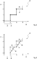
Figur 2 zeigt in einem Diagramm 30 einen ersten Zeitverlauf eines Soll-Stellwerts 21 in einer Ausführungsform des erfindungsgemäßen Verfahrens. In dem Diagramm 30 sind über der Ordinate 31 in lediglich symbolischen Einheiten Steuerwerte 20 bzw. Stellwerte 21 und über der Ordinate 32 in Millisekunden (ms) ein Zeitverlauf abgetragen. Wie dem Diagramm 30 entnommen werden kann, weist ein Übertragungszyklus 23 des Bussystems eine Dauer von 5 ms auf. Die Dauer eines Berechnungszyklus 24 des Aktuators beträgt dagegen 1 ms. - Damit ist die Übertragungszyklusdauer 23 des Bussystems ein ganzzahliges Vielfaches der Berechnungszyklusdauer 24 des Aktuators, und ein Quotient aus der Übertragungszyklusdauer 23 und der Berechnungszyklusdauer 24 beträgt 5. Die von dem Steuergerät erzeugten und über das Bussystem übertragenen Steueranforderungen umfassen eine Schrittzahl mit dem Wert 0. Entsprechend berechnet der Aktuator bei diesem Zeitverlauf des Soll-Stellwerts 21 keine Zwischenwerte, und der Soll-Stellwert 21 folgt sprunghaft den Steuerwerten 20.
- Der in dem Diagramm 30 gezeigte Zeitverlauf des Sollstellwerts 21 stellt also einen Grenzfall des erfindungsgemäßen Verfahrens dar, mit welchem für den Soll-Stellwert 21 ein Zeitverlauf wie aus dem Stand der Technik bewirkt werden kann. Aus Sicht des erfindungsgemäßen Verfahrens kann dieser Grenzfall als sprunghafte "Interpolation" bezeichnet werden.
-
Figur 3 zeigt in einem Diagramm 40 einen zweiten Zeitverlauf eines Soll-Stellwerts 21 in der Ausführungsform des erfindungsgemäßen Verfahrens. In dem Diagramm 40 sind über der Ordinate 41 in lediglich symbolischen Einheiten Steuerwerte 20 bzw. Stellwerte 21 und über der Ordinate 42 in Millisekunden ein Zeitverlauf abgetragen. Wie dem Diagramm 40 entnommen werden kann, weist ein Übertragungszyklus 23 des Bussystems eine Dauer von 5 ms auf. Die Dauer eines Berechnungszyklus 24 des Aktuators beträgt dagegen 1 ms. - Damit ist die Übertragungszyklusdauer 23 des Bussystems ein ganzzahliges Vielfaches der Berechnungszyklusdauer 24 des Aktuators, und ein Quotient aus der Übertragungszyklusdauer 23 und der Berechnungszyklusdauer 24 beträgt 5. Die von dem Steuergerät erzeugten und über das Bussystem übertragenen Steueranforderungen umfassen eine Schrittzahl 25 mit dem Wert 3. Damit sieht das Steuergerät eine Schrittzahl 25 vor, die kleiner ist als der Quotient aus der Übertragungszyklusdauer 23 und der Berechnungszyklusdauer 23.
- Entsprechend berechnet der Aktuator in drei Berechnungszyklusdauern 24 jeweils einen Zwischenwert 22, wobei der dem Steuerwert 20 entsprechende Soll-Stellwert nach drei Berechnungszyklusdauern 24 und folglich vor dem Übertragen der jeweils nächsten Steueranforderung erreicht ist. Dieses Verhalten des Aktuators kann als schnelle Interpolation bezeichnet werden und vermeidet den sprunghaften in
Figur 2 dargestellten Zeitverlauf. -
Figur 4 zeigt in einem Diagramm 50 einen dritten Zeitverlauf eines Soll-Stellwerts 21 in der Ausführungsform des erfindungsgemäßen Verfahrens. In dem Diagramm 50 sind über der Ordinate 51 in lediglich symbolischen Einheiten Steuerwerte 20 bzw. Stellwerte 21 und über der Ordinate 52 in Millisekunden ein Zeitverlauf abgetragen. Wie dem Diagramm 50 entnommen werden kann, weist ein Übertragungszyklus 23 des Bussystems eine Dauer von 5 ms auf. Die Dauer eines Berechnungszyklus 24 des Aktuators beträgt dagegen 1 ms. - Damit ist die Übertragungszyklusdauer 23 des Bussystems ein ganzzahliges Vielfaches der Berechnungszyklusdauer 24 des Aktuators, und ein Quotient aus der Übertragungszyklusdauer 23 und der Berechnungszyklusdauer 24 beträgt 5. Die von dem Steuergerät erzeugten und über das Bussystem übertragenen Steueranforderungen umfassen eine Schrittzahl 25 mit dem Wert 5. Damit sieht das Steuergerät eine Schrittzahl 25 gleich dem Quotienten aus der Übertragungszyklusdauer 23 und der Berechnungszyklusdauer 23 vor.
- Entsprechend berechnet der Aktuator in fünf Berechnungszyklusdauern jeweils einen Zwischenwert 22, wobei der dem Steuerwert 20 entsprechende Soll-Stellwert nach fünf Berechnungszyklusdauern 24 und bei dem Übertragen der jeweils nächsten Steueranforderung erreicht ist. Dieses Verhalten des Aktuators kann als lineare Interpolation bezeichnet werden und approximiert optimal den ursprünglich linearen Zeitverlauf des Steuerwerts 20.
-
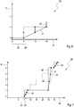
Figur 5 zeigt in einem Diagramm 60 einen vierten Zeitverlauf eines Soll-Stellwerts 21 in der Ausführungsform des erfindungsgemäßen Verfahrens. In dem Diagramm 60 sind über der Ordinate 61 in lediglich symbolischen Einheiten Steuerwerte 20 bzw. Stellwerte 21 und über der Ordinate 62 in Millisekunden ein Zeitverlauf abgetragen. Wie dem Diagramm 60 entnommen werden kann, weist ein Übertragungszyklus 23 des Bussystems eine Dauer von 5 ms auf. Die Dauer eines Berechnungszyklus 24 des Aktuators beträgt dagegen 1 ms. - Damit ist die Übertragungszyklusdauer 23 des Bussystems ein ganzzahliges Vielfaches der Berechnungszyklusdauer 24 des Aktuators, und ein Quotient aus der Übertragungszyklusdauer 23 und der Berechnungszyklusdauer 24 beträgt 5. Die von dem Steuergerät erzeugten und über das Bussystem übertragenen Steueranforderungen umfassen eine Schrittzahl 25 mit dem Wert 7. Damit sieht das Steuergerät eine Schrittzahl 25 vor, die größer ist als der Quotient aus der Übertragungszyklusdauer 23 und der Berechnungszyklusdauer 23.
- Entsprechend berechnet der Aktuator ausgehend von sieben Berechnungszyklusdauern 24 jeweils einen Zwischenwert 22, wobei der dem Steuerwert 20 entsprechende Soll-Stellwert auch erst nach Berechnungszyklusdauern 24 und also nach dem Übertragen der jeweils nächsten Steueranforderung erreicht wäre. Infolgedessen wird der nach fünf Berechnungszyklusdauern 24 erreichte und von dem anvisierten Soll-Stellwert abweichende Stellwert als Ist-Stellwert für eine auf die nächste Steueranforderung folgende Berechnung des Aktuators genommen. Dieses Verhalten des Aktuators kann als langsame Interpolation bezeichnet werden.
-
Figur 6 zeigt in einem Diagramm 70 einen fünften Zeitverlauf eines Soll-Stellwerts 21 in der Ausführungsform des erfindungsgemäßen Verfahrens. In dem Diagramm 70 sind über der Ordinate 71 in lediglich symbolischen Einheiten Steuerwerte 20 bzw. Stellwerte 21 und über der Ordinate 72 in Millisekunden (ms) ein Zeitverlauf abgetragen. Wie dem Diagramm 70 entnommen werden kann, weist ein Übertragungszyklus 23 des Bussystems eine Dauer von 5 ms auf. Die Dauer eines Berechnungszyklus 24 des Aktuators beträgt dagegen 1 ms. - Damit ist die Übertragungszyklusdauer 23 des Bussystems ein ganzzahliges Vielfaches der Berechnungszyklusdauer 24 des Aktuators, und ein Quotient aus der Übertragungszyklusdauer 23 und der Berechnungszyklusdauer 24 beträgt 5. Der dargestellte Zeitverlauf unterscheidet sich von dem in
Figur 4 gezeigten Zeitverlauf dadurch, dass die Änderungsrate des Steuerwerts 20 halbiert ist. -
Figur 7 zeigt in einem Diagramm 80 einen sechsten Zeitverlauf eines Soll-Stellwerts 21 in der Ausführungsform des erfindungsgemäßen Verfahrens. In dem Diagramm 80 sind über der Ordinate 81 in lediglich symbolischen Einheiten Steuerwerte 20 bzw. Stellwerte 21 und über der Ordinate 82 in Millisekunden (ms) ein Zeitverlauf abgetragen. Wie dem Diagramm 80 entnommen werden kann, weist ein Übertragungszyklus 23 des Bussystems eine Dauer von 5 ms auf. Die Dauer eines Berechnungszyklus 24 des Aktuators beträgt dagegen 1 ms. - Damit ist die Übertragungszyklusdauer 23 des Bussystems ein ganzzahliges Vielfaches der Berechnungszyklusdauer 24 des Aktuators, und ein Quotient aus der Übertragungszyklusdauer 23 und der Berechnungszyklusdauer 24 beträgt 5. Die von dem Steuergerät erzeugten und über das Bussystem übertragenen Steueranforderungen umfassen eine Schrittzahl 25 mit dem Wert 3. Damit liegt wie in dem in dem Diagramm 30 gezeigt eine schnelle Interpolation vor.
- Abweichend von dem in
Figur 3 gezeigten Zeitverlauf bleiben hier allerdings beispielsweise infolge von Störungen des Bussystems zwischen den Zeitpunkten 10 ms und 25 ms drei Steueranforderungen aus, bevor ab dem Zeitpunkt 25 ms wieder bestimmungsgemäß Steueranforderungen mit Steuerwerten 20 übertragen werden. Durch die schnelle Interpolation wird der große Sprung zum Zeitpunkt 25 entsprechend abgemildert. - Ein wesentlicher Vorteil des erfindungsgemäßen Verfahrens besteht darin, dass das Steuergerät durch Variieren der Steueranforderungen hinsichtlich der Schrittzahl 25 das Interpolationsverhalten des Aktuators bestimmen kann, um aktuelle Fahrsituationen des Fahrzeugs angemessen zu berücksichtigen. Auf diese Weise wird der Aktuator veranlasst, etwaige Unstetigkeiten der von den Steueranforderungen umfassten Steuerwerte 20 durch Berechnen von Zwischenstellwerten 22 flexibel zu interpolieren, wodurch ein entsprechend weiches Verstellen der von dem Aktuator betätigten Fahrwerkkomponente erreicht wird. Dies geht mit einer Verbesserung der Fahrzeugsicherheit und einer Erhöhung des Fahrkomforts einher.
-
- 10
- Diagramm
- 11
- Ordinate
- 12
- Abszisse
- 13
- Linearfunktion
- 20
- Steuerwert (im Zeitverlauf)
- 21
- Soll-Stellwert (im Zeitverlauf)
- 22
- Zwischenstellwert
- 23
- Übertragungszyklusdauer
- 24
- Berechnungszyklusdauer
- 25
- Schrittzahl
- 30
- Diagramm
- 31
- Ordinate
- 32
- Abszisse
- 40
- Diagramm
- 41
- Ordinate
- 42
- Abszisse
- 50
- Diagramm
- 51
- Ordinate
- 52
- Abszisse
- 60
- Diagramm
- 61
- Ordinate
- 62
- Abszisse
- 70
- Diagramm
- 71
- Ordinate
- 72
- Abszisse
- 80
- Diagramm
- 81
- Ordinate
- 82
- Abszisse
Claims (10)
- Verfahren zum Steuern einer Fahrwerkkomponente eines Fahrzeugs, bei dem- ein Steuergerät der Fahrwerkkomponente fortlaufend entsprechend einer Erzeugungstaktfrequenz mehrere jeweils einen Steuerwert (20) umfassende Steueranforderungen für einen Aktuator der Fahrwerkkomponente erzeugt;- ein Bussystem des Fahrzeugs von dem Steuergerät erzeugte Steueranforderungen fortlaufend entsprechend einer Übertragungstaktfrequenz zu dem Aktuator überträgt;- der Aktuator aus dem Steuerwert (20) jeder übertragenen Steueranforderung und einem Ist-Stellwert der Fahrwerkkomponente einen Soll-Stellwert (21) für die Fahrwerkkomponente berechnet und die Fahrwerkkomponente entsprechend dem berechneten Soll-Stellwert (21) verstellt, und bei dem- der Aktuator zwischen zwei unmittelbar nacheinander übertragenen Steueranforderungen mindestens einen Zwischenstellwert (22) berechnet.
- Verfahren nach Anspruch 1, bei dem der Aktuator zwischen zwei unmittelbar nacheinander übertragenen Steueranforderungen fortlaufend entsprechend einer Berechnungstaktfrequenz mehrere Zwischenstellwerte (22) berechnet.
- Verfahren nach einem der Ansprüche 1 oder 2, bei dem der Aktuator in jeder Berechnungszyklusdauer (24) einen Zwischenstellwert (22) berechnet.
- Verfahren nach einem der Ansprüche 1 bis 3, bei dem das Steuergerät jede erzeugte Steueranforderung mit einer bestimmten Schrittzahl (25) versieht und der Aktuator zwischen zwei unmittelbar nacheinander übertragenen Steueranforderungen höchstens so viele Zwischenstellwerte (22) berechnet, wie die Schrittzahl (25) der übertragenen Steueranforderung vorgibt.
- Verfahren nach einem der Ansprüche 2 bis 4, bei dem der Aktuator die Zwischenstellwerte (22) mittels Interpolierens zwischen dem Ist-Stellwert und dem Soll-Stellwert (21) berechnet, insbesondere mittels linearen Interpolierens.
- Verfahren nach einem der Ansprüche 1 bis 5, bei dem die Berechnungstaktfrequenz des Aktuators höher ist als die Übertragungstaktfrequenz des Bussystems.
- Verfahren nach Anspruch 6, bei dem das Steuergerät die Schrittzahl (25) kleiner als den Quotienten aus der Übertragungszyklusdauer (23) und der Berechnungszyklusdauer (23) vorsieht.
- Verfahren nach Anspruch 6, bei dem das Steuergerät die Schrittzahl (25) gleich dem oder größer als den Quotienten aus der Übertragungszyklusdauer (23) und der Berechnungszyklusdauer (23) vorsieht.
- Verfahren nach einem der Anspruch 6 bis 8, bei dem die Übertragungszyklusdauer (23) des Bussystems ein ganzzahliges Vielfaches der Berechnungszyklusdauer (23) des Aktuators ist und insbesondere das Steuergerät die Schrittzahl (25) gleich dem Quotienten aus der Übertragungszyklusdauer (23) und der Berechnungszyklusdauer (23) vorsieht.
- Fahrwerkkomponente eines Fahrzeugs, mit einem an ein Bussystem des Fahrzeugs anschließbaren Steuergerät, welches konfiguriert ist, fortlaufend entsprechend einer Erzeugungstaktfrequenz mehrere jeweils einen Steuerwert (20) umfassende Steueranforderungen zu erzeugen, und einem an das Bussystem des Fahrzeugs anschließbaren Aktuator, welcher konfiguriert ist, aus dem Steuerwert (20) jeder mittels des Bussystems übertragenen Steueranforderung und einem Ist-Stellwert der Fahrwerkkomponente einen Soll-Stellwert (21) für die Fahrwerkkomponente zu berechnen und die Fahrwerkkomponente entsprechend dem berechneten Soll-Stellwert (21) zu verstellen, bei der der Aktuator konfiguriert ist, zwischen zwei unmittelbar nacheinander übertragenen Steueranforderungen mindestens einen Zwischenstellwert (22) zu berechnen, insbesondere in einem Verfahren nach einem der Ansprüche 1 bis 9.
Applications Claiming Priority (1)
| Application Number | Priority Date | Filing Date | Title |
|---|---|---|---|
| DE102017223331.1A DE102017223331A1 (de) | 2017-12-20 | 2017-12-20 | Steuerung einer Fahrwerkkomponente eines Fahrzeugs |
Publications (2)
| Publication Number | Publication Date |
|---|---|
| EP3505415A1 true EP3505415A1 (de) | 2019-07-03 |
| EP3505415B1 EP3505415B1 (de) | 2021-07-14 |
Family
ID=64664643
Family Applications (1)
| Application Number | Title | Priority Date | Filing Date |
|---|---|---|---|
| EP18211537.8A Active EP3505415B1 (de) | 2017-12-20 | 2018-12-11 | Steuerung einer fahrwerkkomponente eines fahrzeugs |
Country Status (5)
| Country | Link |
|---|---|
| US (1) | US10974563B2 (de) |
| EP (1) | EP3505415B1 (de) |
| KR (1) | KR102135708B1 (de) |
| CN (1) | CN109941292B (de) |
| DE (1) | DE102017223331A1 (de) |
Families Citing this family (1)
| Publication number | Priority date | Publication date | Assignee | Title |
|---|---|---|---|---|
| JP7160060B2 (ja) * | 2020-02-28 | 2022-10-25 | 株式会社デンソー | 舵角制御装置 |
Citations (3)
| Publication number | Priority date | Publication date | Assignee | Title |
|---|---|---|---|---|
| DE102006047954A1 (de) * | 2006-09-05 | 2008-03-06 | Robert Bosch Gmbh | Verfahren zum Regeln eines Antriebssystems und eine elektronische Steuereinheit |
| DE102013220374A1 (de) * | 2013-10-09 | 2015-04-09 | Robert Bosch Gmbh | Teilnehmerstation für ein Bussystem und Verfahren zur breitbandigen CAN-Kommunikation |
| US20170158199A1 (en) * | 2015-12-08 | 2017-06-08 | Ford Global Technologies, Llc | Vehicle acceleration determination |
Family Cites Families (13)
| Publication number | Priority date | Publication date | Assignee | Title |
|---|---|---|---|---|
| GB1525861A (en) * | 1975-10-23 | 1978-09-20 | Mullard Ltd | Vehicle power transmission arrangements and electronic control means therefor |
| US4884227A (en) * | 1987-12-11 | 1989-11-28 | Toyota Jidosha Kabushiki Kaisha | Speed detecting apparatus for a vehicle |
| DE4305155C2 (de) | 1993-02-19 | 2002-05-23 | Bosch Gmbh Robert | Vorrichtung zur Regelung der Fahrdynamik |
| JP3819609B2 (ja) * | 1998-09-25 | 2006-09-13 | 株式会社日立製作所 | 補間制御手段を備えたエンジン制御装置 |
| DE102004040876A1 (de) | 2004-03-11 | 2005-12-29 | Continental Teves Ag & Co. Ohg | Verfahren zur Fahrdynamikregelung eines Fahrzeugs, Vorrichtung zur Durchführung des Verfahrens und ihre Verwendung |
| JP2012034375A (ja) * | 2011-08-22 | 2012-02-16 | Hitachi Automotive Systems Ltd | データ通信装置及びそれを用いたコントローラ |
| DE102012202684A1 (de) | 2012-02-22 | 2013-08-22 | Bayerische Motoren Werke Aktiengesellschaft | Verfahren zur Fahrzeug- und/oder Fahrstabilitätsregelung für Kraftfahrzeuge |
| JP6045211B2 (ja) * | 2012-06-15 | 2016-12-14 | 日野自動車株式会社 | サスペンション制御装置及び車両 |
| EP2770339B1 (de) * | 2013-02-26 | 2019-11-27 | Hexagon Technology Center GmbH | Sensorsynchronisationsverfahren und ebensolches Sensormesssystem |
| EP4450845A3 (de) * | 2013-03-15 | 2025-01-01 | ClearMotion, Inc. | Verbesserungen an einer aktiven fahrzeugaufhängung |
| EP2928110B1 (de) * | 2014-04-01 | 2020-10-07 | Siemens Aktiengesellschaft | Verfahren zur Synchronisation eines isochronen Systems mit einem übergeordneten Taktsystem |
| JP6060938B2 (ja) * | 2014-06-11 | 2017-01-18 | トヨタ自動車株式会社 | 機関制御装置 |
| DE102015003194A1 (de) * | 2015-03-12 | 2016-09-15 | Infineon Technologies Ag | Verfahren und Vorrichtung zum Handhaben von sicherheitskritischen Fehlern |
-
2017
- 2017-12-20 DE DE102017223331.1A patent/DE102017223331A1/de not_active Withdrawn
-
2018
- 2018-12-11 EP EP18211537.8A patent/EP3505415B1/de active Active
- 2018-12-17 US US16/221,827 patent/US10974563B2/en active Active
- 2018-12-18 CN CN201811547702.6A patent/CN109941292B/zh active Active
- 2018-12-20 KR KR1020180166213A patent/KR102135708B1/ko active Active
Patent Citations (3)
| Publication number | Priority date | Publication date | Assignee | Title |
|---|---|---|---|---|
| DE102006047954A1 (de) * | 2006-09-05 | 2008-03-06 | Robert Bosch Gmbh | Verfahren zum Regeln eines Antriebssystems und eine elektronische Steuereinheit |
| DE102013220374A1 (de) * | 2013-10-09 | 2015-04-09 | Robert Bosch Gmbh | Teilnehmerstation für ein Bussystem und Verfahren zur breitbandigen CAN-Kommunikation |
| US20170158199A1 (en) * | 2015-12-08 | 2017-06-08 | Ford Global Technologies, Llc | Vehicle acceleration determination |
Also Published As
| Publication number | Publication date |
|---|---|
| US10974563B2 (en) | 2021-04-13 |
| EP3505415B1 (de) | 2021-07-14 |
| KR20190075005A (ko) | 2019-06-28 |
| US20190184783A1 (en) | 2019-06-20 |
| CN109941292A (zh) | 2019-06-28 |
| KR102135708B1 (ko) | 2020-07-20 |
| DE102017223331A1 (de) | 2019-06-27 |
| CN109941292B (zh) | 2022-04-05 |
Similar Documents
| Publication | Publication Date | Title |
|---|---|---|
| DE102011085422B4 (de) | Fahrzeugbewegung-steuervorrichtung und fahrzeugbewegung-steuerverfahren | |
| EP3374224B1 (de) | Fahrdynamikregelsystem in einem kraftfahrzeug und elektronische fahrdynamiksteuereinheit für ein fahrdynamikregelsystem | |
| DE19857992C2 (de) | Vorrichtung zur kinästhetischen Signalisierung an den Fahrer eines Kraftfahrzeuges | |
| DE19627727B4 (de) | Verfahren und Vorrichtung zur Steuerung der Geschwindigkeit eines Fahrzeugs | |
| DE10231555A1 (de) | Verfahren und Vorrichtung zur automatischen Steuerung der Verzögerungseinrichtung eines Fahrzeugs | |
| DE19616732B4 (de) | Verfahren und Vorrichtung zur Steuerung der Bremsanlage eines Fahrzeugs | |
| DE102017200713B4 (de) | Verfahren zum Erkennen einer Steuerungssituation eines Fahrzeugs mit einem automatischen Steuerungssystem | |
| EP3106961B1 (de) | Aktives fahrpedal für ein fahrzeug | |
| EP4155148B1 (de) | Verfahren und steuervorrichtung zum vermeiden eines kippens eines kraftfahrzeugs mit steer-by-wire lenkung und kraftfahrzeug | |
| EP3922525A1 (de) | Verfahren zur begrenzung einer geschwindigkeit eines nutzfahrzeugs und geschwindigkeitsbegrenzungseinrichtung | |
| EP3672853A1 (de) | Steuervorrichtung und verfahren zum betreiben einer fahrzeugverzögerungsvorrichtung eines fahrzeugs | |
| DE102023202152A1 (de) | Vorrichtung und Verfahren zum Dämpfen einer Lenkbewegung bei einem aktiven Lenksystem eines Fahrzeugs, die Vorrichtung umfassendes Fahrzeug | |
| DE102005025287A1 (de) | Fahrzustandsangepaßte, auf Lenkeingriffen basierende Fahrdynamikregelung | |
| DE19615806A1 (de) | Verfahren und Vorrichtung zur Steuerung einer Antriebseinheit eines Fahrzeuges | |
| EP3947067B1 (de) | Bremsregeleinrichtung, bremsverfahren und bremssystem für ein schienenfahrzeug | |
| EP3505415B1 (de) | Steuerung einer fahrwerkkomponente eines fahrzeugs | |
| DE102009046942A1 (de) | Verfahren zum Betreiben einer Bremsanlage sowie entsprechendes Steuergerät | |
| DE10341412A1 (de) | Fahrdynamikregelsystem für Fahrzeuge | |
| EP1392532A1 (de) | Verfahren und vorrichtung zur dynamischen einstellung einer fahrzeugkomponente | |
| EP2196372B1 (de) | Verfahren zum Steuern einer Beschleunigungseinrichtung für Kraftfahrzeuge | |
| DE102022115515A1 (de) | Regelsystem für ein Kraftfahrzeug sowie Verfahren zur Erzeugung von einem radspezifischen Moment | |
| EP1764277B1 (de) | Verfahren und Vorrichtung zur Geschwindigkeitsregelung eines Kraftfahrzeuges | |
| WO2023066581A1 (de) | Verfahren zum automatisierten anpassen einer antischlupfregelung eines fahrzeugs | |
| DE102024209344B3 (de) | Verfahren zum Betreiben eines Lenkassistenzsystems und Lenkassistenzsystem für ein Fahrzeug | |
| EP4669556B1 (de) | Gesteuert unkomfortables fahrzeug-verhalten bei fahrassistenzsystem-anwendung |
Legal Events
| Date | Code | Title | Description |
|---|---|---|---|
| PUAI | Public reference made under article 153(3) epc to a published international application that has entered the european phase |
Free format text: ORIGINAL CODE: 0009012 |
|
| STAA | Information on the status of an ep patent application or granted ep patent |
Free format text: STATUS: THE APPLICATION HAS BEEN PUBLISHED |
|
| AK | Designated contracting states |
Kind code of ref document: A1 Designated state(s): AL AT BE BG CH CY CZ DE DK EE ES FI FR GB GR HR HU IE IS IT LI LT LU LV MC MK MT NL NO PL PT RO RS SE SI SK SM TR |
|
| AX | Request for extension of the european patent |
Extension state: BA ME |
|
| STAA | Information on the status of an ep patent application or granted ep patent |
Free format text: STATUS: REQUEST FOR EXAMINATION WAS MADE |
|
| 17P | Request for examination filed |
Effective date: 20200103 |
|
| RBV | Designated contracting states (corrected) |
Designated state(s): AL AT BE BG CH CY CZ DE DK EE ES FI FR GB GR HR HU IE IS IT LI LT LU LV MC MK MT NL NO PL PT RO RS SE SI SK SM TR |
|
| STAA | Information on the status of an ep patent application or granted ep patent |
Free format text: STATUS: EXAMINATION IS IN PROGRESS |
|
| 17Q | First examination report despatched |
Effective date: 20201026 |
|
| GRAP | Despatch of communication of intention to grant a patent |
Free format text: ORIGINAL CODE: EPIDOSNIGR1 |
|
| STAA | Information on the status of an ep patent application or granted ep patent |
Free format text: STATUS: GRANT OF PATENT IS INTENDED |
|
| RIC1 | Information provided on ipc code assigned before grant |
Ipc: B60W 50/00 20060101AFI20210324BHEP Ipc: B60W 30/00 20060101ALI20210324BHEP Ipc: B60W 30/02 20120101ALI20210324BHEP Ipc: G08C 15/00 20060101ALI20210324BHEP Ipc: H04L 12/40 20060101ALI20210324BHEP Ipc: B60G 17/00 20060101ALI20210324BHEP Ipc: B62D 6/00 20060101ALI20210324BHEP |
|
| INTG | Intention to grant announced |
Effective date: 20210413 |
|
| GRAS | Grant fee paid |
Free format text: ORIGINAL CODE: EPIDOSNIGR3 |
|
| GRAA | (expected) grant |
Free format text: ORIGINAL CODE: 0009210 |
|
| STAA | Information on the status of an ep patent application or granted ep patent |
Free format text: STATUS: THE PATENT HAS BEEN GRANTED |
|
| AK | Designated contracting states |
Kind code of ref document: B1 Designated state(s): AL AT BE BG CH CY CZ DE DK EE ES FI FR GB GR HR HU IE IS IT LI LT LU LV MC MK MT NL NO PL PT RO RS SE SI SK SM TR |
|
| REG | Reference to a national code |
Ref country code: GB Ref legal event code: FG4D Free format text: NOT ENGLISH |
|
| REG | Reference to a national code |
Ref country code: IE Ref legal event code: FG4D Free format text: LANGUAGE OF EP DOCUMENT: GERMAN |
|
| REG | Reference to a national code |
Ref country code: DE Ref legal event code: R096 Ref document number: 502018006122 Country of ref document: DE |
|
| REG | Reference to a national code |
Ref country code: AT Ref legal event code: REF Ref document number: 1410411 Country of ref document: AT Kind code of ref document: T Effective date: 20210815 |
|
| REG | Reference to a national code |
Ref country code: LT Ref legal event code: MG9D |
|
| REG | Reference to a national code |
Ref country code: NL Ref legal event code: MP Effective date: 20210714 |
|
| PG25 | Lapsed in a contracting state [announced via postgrant information from national office to epo] |
Ref country code: PT Free format text: LAPSE BECAUSE OF FAILURE TO SUBMIT A TRANSLATION OF THE DESCRIPTION OR TO PAY THE FEE WITHIN THE PRESCRIBED TIME-LIMIT Effective date: 20211115 Ref country code: NO Free format text: LAPSE BECAUSE OF FAILURE TO SUBMIT A TRANSLATION OF THE DESCRIPTION OR TO PAY THE FEE WITHIN THE PRESCRIBED TIME-LIMIT Effective date: 20211014 Ref country code: NL Free format text: LAPSE BECAUSE OF FAILURE TO SUBMIT A TRANSLATION OF THE DESCRIPTION OR TO PAY THE FEE WITHIN THE PRESCRIBED TIME-LIMIT Effective date: 20210714 Ref country code: LT Free format text: LAPSE BECAUSE OF FAILURE TO SUBMIT A TRANSLATION OF THE DESCRIPTION OR TO PAY THE FEE WITHIN THE PRESCRIBED TIME-LIMIT Effective date: 20210714 Ref country code: BG Free format text: LAPSE BECAUSE OF FAILURE TO SUBMIT A TRANSLATION OF THE DESCRIPTION OR TO PAY THE FEE WITHIN THE PRESCRIBED TIME-LIMIT Effective date: 20211014 Ref country code: SE Free format text: LAPSE BECAUSE OF FAILURE TO SUBMIT A TRANSLATION OF THE DESCRIPTION OR TO PAY THE FEE WITHIN THE PRESCRIBED TIME-LIMIT Effective date: 20210714 Ref country code: RS Free format text: LAPSE BECAUSE OF FAILURE TO SUBMIT A TRANSLATION OF THE DESCRIPTION OR TO PAY THE FEE WITHIN THE PRESCRIBED TIME-LIMIT Effective date: 20210714 Ref country code: HR Free format text: LAPSE BECAUSE OF FAILURE TO SUBMIT A TRANSLATION OF THE DESCRIPTION OR TO PAY THE FEE WITHIN THE PRESCRIBED TIME-LIMIT Effective date: 20210714 Ref country code: ES Free format text: LAPSE BECAUSE OF FAILURE TO SUBMIT A TRANSLATION OF THE DESCRIPTION OR TO PAY THE FEE WITHIN THE PRESCRIBED TIME-LIMIT Effective date: 20210714 Ref country code: FI Free format text: LAPSE BECAUSE OF FAILURE TO SUBMIT A TRANSLATION OF THE DESCRIPTION OR TO PAY THE FEE WITHIN THE PRESCRIBED TIME-LIMIT Effective date: 20210714 |
|
| PG25 | Lapsed in a contracting state [announced via postgrant information from national office to epo] |
Ref country code: PL Free format text: LAPSE BECAUSE OF FAILURE TO SUBMIT A TRANSLATION OF THE DESCRIPTION OR TO PAY THE FEE WITHIN THE PRESCRIBED TIME-LIMIT Effective date: 20210714 Ref country code: LV Free format text: LAPSE BECAUSE OF FAILURE TO SUBMIT A TRANSLATION OF THE DESCRIPTION OR TO PAY THE FEE WITHIN THE PRESCRIBED TIME-LIMIT Effective date: 20210714 Ref country code: GR Free format text: LAPSE BECAUSE OF FAILURE TO SUBMIT A TRANSLATION OF THE DESCRIPTION OR TO PAY THE FEE WITHIN THE PRESCRIBED TIME-LIMIT Effective date: 20211015 |
|
| REG | Reference to a national code |
Ref country code: DE Ref legal event code: R097 Ref document number: 502018006122 Country of ref document: DE |
|
| PG25 | Lapsed in a contracting state [announced via postgrant information from national office to epo] |
Ref country code: DK Free format text: LAPSE BECAUSE OF FAILURE TO SUBMIT A TRANSLATION OF THE DESCRIPTION OR TO PAY THE FEE WITHIN THE PRESCRIBED TIME-LIMIT Effective date: 20210714 |
|
| PLBE | No opposition filed within time limit |
Free format text: ORIGINAL CODE: 0009261 |
|
| STAA | Information on the status of an ep patent application or granted ep patent |
Free format text: STATUS: NO OPPOSITION FILED WITHIN TIME LIMIT |
|
| PG25 | Lapsed in a contracting state [announced via postgrant information from national office to epo] |
Ref country code: SM Free format text: LAPSE BECAUSE OF FAILURE TO SUBMIT A TRANSLATION OF THE DESCRIPTION OR TO PAY THE FEE WITHIN THE PRESCRIBED TIME-LIMIT Effective date: 20210714 Ref country code: SK Free format text: LAPSE BECAUSE OF FAILURE TO SUBMIT A TRANSLATION OF THE DESCRIPTION OR TO PAY THE FEE WITHIN THE PRESCRIBED TIME-LIMIT Effective date: 20210714 Ref country code: RO Free format text: LAPSE BECAUSE OF FAILURE TO SUBMIT A TRANSLATION OF THE DESCRIPTION OR TO PAY THE FEE WITHIN THE PRESCRIBED TIME-LIMIT Effective date: 20210714 Ref country code: EE Free format text: LAPSE BECAUSE OF FAILURE TO SUBMIT A TRANSLATION OF THE DESCRIPTION OR TO PAY THE FEE WITHIN THE PRESCRIBED TIME-LIMIT Effective date: 20210714 Ref country code: CZ Free format text: LAPSE BECAUSE OF FAILURE TO SUBMIT A TRANSLATION OF THE DESCRIPTION OR TO PAY THE FEE WITHIN THE PRESCRIBED TIME-LIMIT Effective date: 20210714 Ref country code: AL Free format text: LAPSE BECAUSE OF FAILURE TO SUBMIT A TRANSLATION OF THE DESCRIPTION OR TO PAY THE FEE WITHIN THE PRESCRIBED TIME-LIMIT Effective date: 20210714 |
|
| 26N | No opposition filed |
Effective date: 20220419 |
|
| PG25 | Lapsed in a contracting state [announced via postgrant information from national office to epo] |
Ref country code: MC Free format text: LAPSE BECAUSE OF FAILURE TO SUBMIT A TRANSLATION OF THE DESCRIPTION OR TO PAY THE FEE WITHIN THE PRESCRIBED TIME-LIMIT Effective date: 20210714 Ref country code: IT Free format text: LAPSE BECAUSE OF FAILURE TO SUBMIT A TRANSLATION OF THE DESCRIPTION OR TO PAY THE FEE WITHIN THE PRESCRIBED TIME-LIMIT Effective date: 20210714 |
|
| REG | Reference to a national code |
Ref country code: CH Ref legal event code: PL |
|
| REG | Reference to a national code |
Ref country code: BE Ref legal event code: MM Effective date: 20211231 |
|
| PG25 | Lapsed in a contracting state [announced via postgrant information from national office to epo] |
Ref country code: LU Free format text: LAPSE BECAUSE OF NON-PAYMENT OF DUE FEES Effective date: 20211211 Ref country code: IE Free format text: LAPSE BECAUSE OF NON-PAYMENT OF DUE FEES Effective date: 20211211 |
|
| PG25 | Lapsed in a contracting state [announced via postgrant information from national office to epo] |
Ref country code: BE Free format text: LAPSE BECAUSE OF NON-PAYMENT OF DUE FEES Effective date: 20211231 |
|
| PG25 | Lapsed in a contracting state [announced via postgrant information from national office to epo] |
Ref country code: LI Free format text: LAPSE BECAUSE OF NON-PAYMENT OF DUE FEES Effective date: 20211231 Ref country code: CH Free format text: LAPSE BECAUSE OF NON-PAYMENT OF DUE FEES Effective date: 20211231 |
|
| PG25 | Lapsed in a contracting state [announced via postgrant information from national office to epo] |
Ref country code: CY Free format text: LAPSE BECAUSE OF FAILURE TO SUBMIT A TRANSLATION OF THE DESCRIPTION OR TO PAY THE FEE WITHIN THE PRESCRIBED TIME-LIMIT Effective date: 20210714 |
|
| P01 | Opt-out of the competence of the unified patent court (upc) registered |
Effective date: 20230530 |
|
| PG25 | Lapsed in a contracting state [announced via postgrant information from national office to epo] |
Ref country code: HU Free format text: LAPSE BECAUSE OF FAILURE TO SUBMIT A TRANSLATION OF THE DESCRIPTION OR TO PAY THE FEE WITHIN THE PRESCRIBED TIME-LIMIT; INVALID AB INITIO Effective date: 20181211 |
|
| PG25 | Lapsed in a contracting state [announced via postgrant information from national office to epo] |
Ref country code: MK Free format text: LAPSE BECAUSE OF FAILURE TO SUBMIT A TRANSLATION OF THE DESCRIPTION OR TO PAY THE FEE WITHIN THE PRESCRIBED TIME-LIMIT Effective date: 20210714 |
|
| PG25 | Lapsed in a contracting state [announced via postgrant information from national office to epo] |
Ref country code: MT Free format text: LAPSE BECAUSE OF FAILURE TO SUBMIT A TRANSLATION OF THE DESCRIPTION OR TO PAY THE FEE WITHIN THE PRESCRIBED TIME-LIMIT Effective date: 20210714 |
|
| REG | Reference to a national code |
Ref country code: AT Ref legal event code: MM01 Ref document number: 1410411 Country of ref document: AT Kind code of ref document: T Effective date: 20231211 |
|
| PG25 | Lapsed in a contracting state [announced via postgrant information from national office to epo] |
Ref country code: AT Free format text: LAPSE BECAUSE OF NON-PAYMENT OF DUE FEES Effective date: 20231211 |
|
| PG25 | Lapsed in a contracting state [announced via postgrant information from national office to epo] |
Ref country code: TR Free format text: LAPSE BECAUSE OF FAILURE TO SUBMIT A TRANSLATION OF THE DESCRIPTION OR TO PAY THE FEE WITHIN THE PRESCRIBED TIME-LIMIT Effective date: 20210714 |
|
| PGFP | Annual fee paid to national office [announced via postgrant information from national office to epo] |
Ref country code: GB Payment date: 20251218 Year of fee payment: 8 |
|
| PGFP | Annual fee paid to national office [announced via postgrant information from national office to epo] |
Ref country code: FR Payment date: 20251217 Year of fee payment: 8 |
|
| PGFP | Annual fee paid to national office [announced via postgrant information from national office to epo] |
Ref country code: DE Payment date: 20251231 Year of fee payment: 8 |
|
| PGFP | Annual fee paid to national office [announced via postgrant information from national office to epo] |
Ref country code: AT Payment date: 20260410 Year of fee payment: 5 |