EP3503026A1 - Dispositif, système et procédé pour interagir avec des images de vaisseau - Google Patents
Dispositif, système et procédé pour interagir avec des images de vaisseau Download PDFInfo
- Publication number
- EP3503026A1 EP3503026A1 EP17306839.6A EP17306839A EP3503026A1 EP 3503026 A1 EP3503026 A1 EP 3503026A1 EP 17306839 A EP17306839 A EP 17306839A EP 3503026 A1 EP3503026 A1 EP 3503026A1
- Authority
- EP
- European Patent Office
- Prior art keywords
- vessel
- contour
- image
- indicated portion
- processing unit
- Prior art date
- Legal status (The legal status is an assumption and is not a legal conclusion. Google has not performed a legal analysis and makes no representation as to the accuracy of the status listed.)
- Withdrawn
Links
Images

Classifications
-
- G—PHYSICS
- G06—COMPUTING; CALCULATING OR COUNTING
- G06F—ELECTRIC DIGITAL DATA PROCESSING
- G06F3/00—Input arrangements for transferring data to be processed into a form capable of being handled by the computer; Output arrangements for transferring data from processing unit to output unit, e.g. interface arrangements
- G06F3/01—Input arrangements or combined input and output arrangements for interaction between user and computer
- G06F3/048—Interaction techniques based on graphical user interfaces [GUI]
- G06F3/0484—Interaction techniques based on graphical user interfaces [GUI] for the control of specific functions or operations, e.g. selecting or manipulating an object, an image or a displayed text element, setting a parameter value or selecting a range
- G06F3/04845—Interaction techniques based on graphical user interfaces [GUI] for the control of specific functions or operations, e.g. selecting or manipulating an object, an image or a displayed text element, setting a parameter value or selecting a range for image manipulation, e.g. dragging, rotation, expansion or change of colour
-
- G—PHYSICS
- G06—COMPUTING; CALCULATING OR COUNTING
- G06T—IMAGE DATA PROCESSING OR GENERATION, IN GENERAL
- G06T7/00—Image analysis
- G06T7/10—Segmentation; Edge detection
- G06T7/12—Edge-based segmentation
-
- G—PHYSICS
- G06—COMPUTING; CALCULATING OR COUNTING
- G06F—ELECTRIC DIGITAL DATA PROCESSING
- G06F3/00—Input arrangements for transferring data to be processed into a form capable of being handled by the computer; Output arrangements for transferring data from processing unit to output unit, e.g. interface arrangements
- G06F3/01—Input arrangements or combined input and output arrangements for interaction between user and computer
- G06F3/048—Interaction techniques based on graphical user interfaces [GUI]
- G06F3/0487—Interaction techniques based on graphical user interfaces [GUI] using specific features provided by the input device, e.g. functions controlled by the rotation of a mouse with dual sensing arrangements, or of the nature of the input device, e.g. tap gestures based on pressure sensed by a digitiser
- G06F3/0488—Interaction techniques based on graphical user interfaces [GUI] using specific features provided by the input device, e.g. functions controlled by the rotation of a mouse with dual sensing arrangements, or of the nature of the input device, e.g. tap gestures based on pressure sensed by a digitiser using a touch-screen or digitiser, e.g. input of commands through traced gestures
-
- G—PHYSICS
- G06—COMPUTING; CALCULATING OR COUNTING
- G06T—IMAGE DATA PROCESSING OR GENERATION, IN GENERAL
- G06T7/00—Image analysis
- G06T7/10—Segmentation; Edge detection
- G06T7/13—Edge detection
-
- G—PHYSICS
- G06—COMPUTING; CALCULATING OR COUNTING
- G06T—IMAGE DATA PROCESSING OR GENERATION, IN GENERAL
- G06T7/00—Image analysis
- G06T7/10—Segmentation; Edge detection
- G06T7/149—Segmentation; Edge detection involving deformable models, e.g. active contour models
-
- G—PHYSICS
- G06—COMPUTING; CALCULATING OR COUNTING
- G06T—IMAGE DATA PROCESSING OR GENERATION, IN GENERAL
- G06T7/00—Image analysis
- G06T7/10—Segmentation; Edge detection
- G06T7/187—Segmentation; Edge detection involving region growing; involving region merging; involving connected component labelling
-
- G—PHYSICS
- G06—COMPUTING; CALCULATING OR COUNTING
- G06F—ELECTRIC DIGITAL DATA PROCESSING
- G06F3/00—Input arrangements for transferring data to be processed into a form capable of being handled by the computer; Output arrangements for transferring data from processing unit to output unit, e.g. interface arrangements
- G06F3/01—Input arrangements or combined input and output arrangements for interaction between user and computer
- G06F3/03—Arrangements for converting the position or the displacement of a member into a coded form
- G06F3/033—Pointing devices displaced or positioned by the user, e.g. mice, trackballs, pens or joysticks; Accessories therefor
- G06F3/0354—Pointing devices displaced or positioned by the user, e.g. mice, trackballs, pens or joysticks; Accessories therefor with detection of 2D relative movements between the device, or an operating part thereof, and a plane or surface, e.g. 2D mice, trackballs, pens or pucks
- G06F3/03543—Mice or pucks
-
- G—PHYSICS
- G06—COMPUTING; CALCULATING OR COUNTING
- G06F—ELECTRIC DIGITAL DATA PROCESSING
- G06F3/00—Input arrangements for transferring data to be processed into a form capable of being handled by the computer; Output arrangements for transferring data from processing unit to output unit, e.g. interface arrangements
- G06F3/01—Input arrangements or combined input and output arrangements for interaction between user and computer
- G06F3/03—Arrangements for converting the position or the displacement of a member into a coded form
- G06F3/033—Pointing devices displaced or positioned by the user, e.g. mice, trackballs, pens or joysticks; Accessories therefor
- G06F3/0354—Pointing devices displaced or positioned by the user, e.g. mice, trackballs, pens or joysticks; Accessories therefor with detection of 2D relative movements between the device, or an operating part thereof, and a plane or surface, e.g. 2D mice, trackballs, pens or pucks
- G06F3/03545—Pens or stylus
-
- G—PHYSICS
- G06—COMPUTING; CALCULATING OR COUNTING
- G06T—IMAGE DATA PROCESSING OR GENERATION, IN GENERAL
- G06T2200/00—Indexing scheme for image data processing or generation, in general
- G06T2200/04—Indexing scheme for image data processing or generation, in general involving 3D image data
-
- G—PHYSICS
- G06—COMPUTING; CALCULATING OR COUNTING
- G06T—IMAGE DATA PROCESSING OR GENERATION, IN GENERAL
- G06T2200/00—Indexing scheme for image data processing or generation, in general
- G06T2200/24—Indexing scheme for image data processing or generation, in general involving graphical user interfaces [GUIs]
-
- G—PHYSICS
- G06—COMPUTING; CALCULATING OR COUNTING
- G06T—IMAGE DATA PROCESSING OR GENERATION, IN GENERAL
- G06T2207/00—Indexing scheme for image analysis or image enhancement
- G06T2207/10—Image acquisition modality
- G06T2207/10072—Tomographic images
- G06T2207/10081—Computed x-ray tomography [CT]
-
- G—PHYSICS
- G06—COMPUTING; CALCULATING OR COUNTING
- G06T—IMAGE DATA PROCESSING OR GENERATION, IN GENERAL
- G06T2207/00—Indexing scheme for image analysis or image enhancement
- G06T2207/10—Image acquisition modality
- G06T2207/10072—Tomographic images
- G06T2207/10088—Magnetic resonance imaging [MRI]
-
- G—PHYSICS
- G06—COMPUTING; CALCULATING OR COUNTING
- G06T—IMAGE DATA PROCESSING OR GENERATION, IN GENERAL
- G06T2207/00—Indexing scheme for image analysis or image enhancement
- G06T2207/10—Image acquisition modality
- G06T2207/10072—Tomographic images
- G06T2207/10104—Positron emission tomography [PET]
-
- G—PHYSICS
- G06—COMPUTING; CALCULATING OR COUNTING
- G06T—IMAGE DATA PROCESSING OR GENERATION, IN GENERAL
- G06T2207/00—Indexing scheme for image analysis or image enhancement
- G06T2207/10—Image acquisition modality
- G06T2207/10072—Tomographic images
- G06T2207/10108—Single photon emission computed tomography [SPECT]
-
- G—PHYSICS
- G06—COMPUTING; CALCULATING OR COUNTING
- G06T—IMAGE DATA PROCESSING OR GENERATION, IN GENERAL
- G06T2207/00—Indexing scheme for image analysis or image enhancement
- G06T2207/10—Image acquisition modality
- G06T2207/10116—X-ray image
-
- G—PHYSICS
- G06—COMPUTING; CALCULATING OR COUNTING
- G06T—IMAGE DATA PROCESSING OR GENERATION, IN GENERAL
- G06T2207/00—Indexing scheme for image analysis or image enhancement
- G06T2207/20—Special algorithmic details
- G06T2207/20092—Interactive image processing based on input by user
-
- G—PHYSICS
- G06—COMPUTING; CALCULATING OR COUNTING
- G06T—IMAGE DATA PROCESSING OR GENERATION, IN GENERAL
- G06T2207/00—Indexing scheme for image analysis or image enhancement
- G06T2207/30—Subject of image; Context of image processing
- G06T2207/30004—Biomedical image processing
- G06T2207/30101—Blood vessel; Artery; Vein; Vascular
Definitions
- the present invention relates to a device, a system and a method for interacting with vessel images.
- X-ray imaging devices e.g. X-ray angiography devices
- a diagnose of the patient may be performed by visually inspecting the acquired X-ray images.
- Computers may be incorporated to the X-ray imaging devices to analyze the X-ray images and provide additional information.
- the users, e.g. clinicians, may interact with the computer programs on those computer to edit or amend the X-ray images.
- Touch interfaces such as tablets, provide a convenient way to implement the editing of X-ray images into the workflow. Touch interfaces may be fixed next to the operation table. They may further be used under a sterile transparent cover, and they allow for intuitive interactions like other applications present in smartphones, like zooming, panning, etc.
- US 2014/0146076 A1 describes an apparatus including an interface unit and a contour modification unit.
- the contour modification unit is configured to modify a contour which is displayed on a display, wherein the modification is based on a user-selected mode from one or more modes, and an operation by a user.
- the task of delineating or correcting vessel contours is very specific to a medical setup. It requires much more accuracy than common tasks like zooming or panning, and in addition, it needs to be intuitive, easy, effective, and efficient. The need for high accuracy is hampered by the fact that touch actions are performed with the finger of the user.
- a device for interacting with vessel images comprising: an interface unit; a processing unit; wherein the interface unit comprises: a display; and an input setup; wherein the display is configured to display a vessel image; wherein the input setup is configured to receive a user input in relation to the vessel image; wherein the processing unit is configured to: determine, for at least one vessel in the vessel image, a vessel contour; determine, from the user input, an identifier position in the vessel image; indicate at least a portion of the vessel contour in the vessel image, if the determined identifier position is spaced apart from the vessel contour by a distance within a predefined distance range; determine, from the user input, a drag direction; and move the indicated portion along the contour based on the determined drag direction.
- the display of the interface unit thus displays a vessel image to a user.
- the processing unit examines the vessel image for a vessel contour.
- the display may indicate a portion of the determined vessel contour in the vessel image.
- the indication may be a line being overlaid on the vessel image.
- the indication may be a change of color or a frame, etc.
- the indicated contour portion describes the complete contour of a vessel.
- the vessel may be represented by a reformatted vessel in the image
- a vessel centreline may be represented by a reformatted vessel centreline in the image
- a vessel contour may be represented by a reformatted vessel contour.
- the user who may for example be a surgeon may examine the determined displayed vessel contour and check whether the determined vessel contour is accurate.
- a correction of the determined vessel contour may be performed by using the input setup.
- the user may provide a position in the vessel image by defining an identifier position with an identifier on the vessel image. If the input setup is for example a touch screen, the identifier may be a finger touching the touch screen.
- the processing unit may consider the user input as start of the interaction with the vessel contour if the identifier position is spaced apart from the vessel contour in the vessel image by a distance within a predefined distance range.
- the required distance between the identifier position and the vessel contour avoids an occlusion of the vessel and the vessel contour in the vessel image.
- the predefined distance range may therefore ensure that an identifier position inside a vessel will not be determined as start of the interaction with the vessel image.
- the processing unit determines an identifier position that is spaced apart from the determined vessel contour
- the processing unit will indicate a portion of the determined vessel contour in the vessel image. That indicated portion shows the user the portion of the vessel contour which may be corrected.
- the user may change the position of the portion along the vessel contour by inputting a drag interaction.
- the processing unit determines the drag direction of the user input and moves the indicated portion along the contour based on the determined drag direction.
- the device improves the accuracy of the interaction with the vessel contour of the vessel image since the identifier does not block the view on the vessels, the determined vessel contour, or the indicated portion in the vessel image.
- the user may then perform modifications to the vessel contour with high accuracy since the user can always see the amended objects in the vessel image.
- the processing unit is further configured to: move the indicated portion along the vessel contour while an angle between the determined drag direction and the indicated portion is within a first predefined angle range.
- the first predefined angle range avoids inaccurate movement of the indicated portion along the vessel contour. Furthermore, the first predefined angle range covers only a portion of the full circle such that further angle ranges for further interaction modes with the vessel contour may be defined. This further ensures a clear determination of the drag direction. Thus, the accuracy of the interaction with the vessel image is further improved.
- the first predefined range ranges from +45 ° to -45 ° and +135 ° to -135 °, preferably from +30 ° to -30 ° and +150 ° to -150 °, more preferably from +15 ° to -15 ° and +165 ° to -165 °, most preferably at 0 ° and 180 °.
- the drag direction is parallel to the indicated contour portion.
- the processing unit is further configured to deform the vessel contour at the indicated portion while the angle between the drag direction and the indicated portion is within a second predefined angle range, resulting in a deformed indicated portion of the vessel contour in the image.
- the deformation of the vessel contour provides an intuitive way to interact with the vessel image to amend the vessel contour at and/or around the position of the indicated portion.
- the user may amend the vessel contour such that the vessel contour fits to the vessel in the vessel image.
- the second predefined angle range provides a further interaction mode in addition to the movement of the indicated portion along the vessel contour.
- the user may also directly deform the vessel contour without moving the indicated portion along the vessel by inputting a drag direction which has an angle with the vessel contour that is in the second predefined angle range right after the indicated portion is provided by the processing unit.
- the second predefined angle range ranges from +45 ° to +135 ° and from -45 ° to -135 °, preferably from +30° to +120 ° and from -30 ° to -120 °, more preferably from +15 to +105 ° and from -15 ° to -105 °, most preferably at +90 ° and at -90 .
- the drag direction is perpendicular to the indicated contour portion.
- the processing unit is further configured to move the deformed indicated portion along the vessel contour in the image while the angle between the drag direction and the indicated portion is within a first predefined range after deforming the vessel contour. That is, when, after a perpendicular drag by which the indicated contour portion has been deformed, the drag direction changes to a direction parallel to the indicated contour portion, the deformed indicated portion is moved along the vessel contour.
- This provides a further interaction with the vessel image wherein the user may move the deformed indicated portion to accurately position the deformed indicated portion of the vessel contour in the vessel image. This further improves the accuracy of the interaction with the vessel image.
- the processing unit is further configured to increase a length of the indicated contour portion with a predefined growth rate before determining the drag direction.
- This provides the interaction to amend the size of the indicated portion at the initiation of the interaction process. Due to the amendment of the size, a user can adapt the size of the indicated portion such that the indicated portion fits to a region of the determined vessel contour that shall be corrected. This further increases the accuracy of the interaction process.
- a period of increasing the length begins with the detection of the identifier position and ends with the detection of the drag direction.
- the interface unit is a touch screen, wherein the user input takes place by a touch interaction on the display within the vessel image.
- the input setup is a mouse, and/or an electronic pen.
- the predefined distance range ranges from 1 mm to 50 mm, preferably from 2 mm to 40 mm, more preferably from 3 mm to 30 mm, most preferably from 4 mm to 20 mm.
- the processing unit is further configured to replace a vessel in the image by a reformatted vessel, a vessel centreline by a reformatted vessel centreline, and/or the vessel contour by a reformatted vessel contour.
- the processing unit is further configured to straighten a curvilinear reformatting of vessel anatomy.
- a system for interacting with vessel images comprising: an image acquisition device; and a device for interacting with vessel images according to the above description; wherein the image acquisition device is configured to acquire and provide a vessel image; and wherein the device for interacting with vessel images is configured to receive the vessel image.
- the image acquisition device is configured to provide two-dimensional image data of a vessel image, wherein the image acquisition device is an angiography device.
- the two-dimensional image acquisition device may be an ultrasound device.
- the image acquisition device is a three-dimensional image acquisition device, preferably a three-dimensional X-ray image acquisition device, more preferably a CT device, a MR device, a PET device, or a SPECT device, wherein the three-dimensional image acquisition device provides a 2D slice of a 3D data set or a 2D projection of a 3D data set is provided.
- a method for interacting with vessel images comprising the following steps: a) Displaying a vessel image on a display of an interface unit; b) Determining, for at least one vessel in the vessel image, a vessel contour; c) Determining, from the user input, an identifier position in the vessel image; d) Indicating at least a portion of the vessel contour in the vessel image, if the determined identifier position is spaced apart from the vessel contour by a distance within a predefined distance range; e) Determining, from the user input, a drag direction; and f) Moving the indicated portion along the contour based on the determined drag direction.
- a computer program element for controlling a device according to the above description or a system according to the above description is provided, which, when being executed by a processing unit, is adapted to perform the method steps according to the above description.
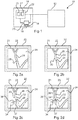
- Fig. 1 shows a system 10 for interacting with vessel images comprising an image acquisition device 12 and a device 14 for interacting with vessel images.
- the image acquisition device 12 is configured to acquire and provide a vessel image 24.
- the device 14 for interacting with vessel images is configured to receive the vessel image 24.
- the vessel image 24 may depict at least one vessel 26.
- the vessel 26 in the vessel image 24 may be replaced by a reformatted vessel, a vessel centreline by a reformatted vessel centreline, and/or the vessel contour by a reformatted vessel contour.
- the vessel image 24 may show a straightened curvilinear reformatting of vessel anatomy.
- the image acquisition device 12 may to provide two-dimensional image data of the vessel image 24, wherein the image acquisition device 12 is an angiography device.
- two-dimensional image data may be extracted from image data being acquired by an ultrasound device, a CT device, a MR device, a PET device, or a SPECT device.
- the two-dimensional image data may be a two-dimensional slice or a two-dimensional projection of a three-dimensional data set.
- the device 14 comprises an interface unit 22, a processing unit 20 and a display 21. After receiving the vessel image 24, the device may display the vessel image 24 on the display 21 as shown in Fig. 2a .
- a user may interact with the vessel image 24 using the interface unit 22.
- the user may provide a user input in relation to the vessel image 24 which may be received by the interface unit 22.
- the user input may comprise an identifier position 36 in the vessel image 24 and further a drag direction 42 being performed by the identifier in the vessel image 24.
- the interface unit 22 is a touch screen comprising the display 21 and a touch controller 23.
- the identifier in the vessel image 24 may be a user's finger which touches the touch screen.
- the surface of the touch screen is then monitored and a touch interaction may be received and processed by the touch controller 23.
- this does not exclude another body part of the user that may be used for touching the touch screen.
- the touch controller 23 of the touch screen may then detect the touch position of the user's finger as identifier position 36 on the vessel image 24.
- the processing unit 20 may register the detected position on the touch screen to a position in the vessel image 24. If the user then performs a drag movement the identifier on the touch screen, the touch controller 23 will detect the drag direction 42.
- the processing unit 20 may determine a vessel contour 30 of the at least one vessel 26 in the vessel image 24, according to Fig. 2b . Furthermore, the processing unit 20 may provide an indication of just a part of the vessel contour 30 in the vessel image 24. The indicated part of the vessel contour 30 may be shown in the vessel image 24 on the display 21. Moreover, the processing unit 20 may determine a further vessel contour 32 in the vessel image 24. The further vessel contour 32 may be positioned opposite to the vessel contour 30 at the vessel 26.
- Fig. 2b it is furthermore shown that the determined vessel contour 30 does not follow the real structure of the vessel 26 in the vessel image 24, wherein the vessel 26 comprises a stenosis 28. As can be seen, the determined vessel contour 30 does not follow the stenosis 28. In this case, the processing unit 20 allows a user to correct the vessel contour 30.
- a user may touch the touch screen of the interface unit 22 with his finger 34 and provide a user input.
- the touch position defines the identifier position 36 in the vessel image 24 which may be determined by the processor unit 20 via the touch controller 23, i.e. in this embodiment by the touch screen.
- the processing unit will indicate at least a portion 38 of the vessel contour 30 in the vessel image 24, as shown in Fig. 2d .
- the predefined distance range within which the distance 37 may range from 1 mm to 50 mm, preferably from 2 mm to 40 mm, more preferably from 3 mm to 30 mm, most preferably from 4 mm to 20 mm from the vessel contour 30.
- the processing unit 20 indicate at least a portion 38 of the vessel contour 30 in the vessel image 24.
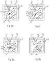
- the indicated portion 38 of the vessel contour 30 will increase its length as shown in Fig. 2e .
- the increase of the length of the indicated portion 38 will take place. This means, that the period of increasing the length of the indicated portion 38 begins with the detection of the identifier position 36 and ends with the detection of the drag direction 42.
- the growth rate of the increase may be predefined and be chosen such that the user can accurately define the size of the indicated portion 38 on the vessel contour 30.
- the drag direction 42 may be detected by the touch controller 23 and determined by the processor unit 20. Upon detection of the drag direction 42, the processing unit 20 will determine the angle between the drag direction and the indicated portion 38 of the vessel contour 30. If the result of the angle determination is within a first predefined angle range 33, the indicated portion 38 of the vessel contour 30 will be moved along the vessel contour 30 by the processor unit 20. The movement follows the identifier, i.e. the user's finger, in the drag direction 42, as is shown in Fig. 2f . In this exemplary embodiment, the user may drag his finger from the identifier position 36 to the position 40 in the vessel image 24. Between Fig. 2e and Fig. 2f , the indicated portion 38 moves along the vessel contour 30 from the beginning of the stenosis 28 to substantially the center of the stenosis 28.
- the identifier i.e. the user's finger
- Fig. 2g shows a change of the drag movement into a direction 46 from the position 40 to the position 44 wherein the drag movement along the direction 46 may be received by touch controller 23.
- the processing unit 20 Upon the determination of the drag movement along the direction 46, the processing unit 20 will determine whether the angle between the direction 46 and the indicated portion 38 is within a second predefined angle range 35. If the determined angle is within the second predefined angle range 35 the vessel contour 30 is default at and/or around the position of the indicated portion 38. The deformation may be such that the indicated portion 38 will move perpendicular to the earlier extension of vessel contour 30. The connection to the remaining vessel contour 30 is adapted to the movement of the indicated portion 38.
- the deformed vessel contour 30 still differs from the stenosis 28.
- the user may perform a further change of the drag movement into the direction 48 starting at the position 44. If the angle between the drag movement along the direction 48 and the indicated portion 38 is in the range of the first predefined angle range 33, the indicated portion 38 will move with the deformed vessel contour 30 along the vessel contour 30 based on the direction 48.
- the deformed portion of the vessel contour 30 may then be moved along the vessel contour 30. This may result in an exact covering of the contour of the stenosis 28 such that the vessel contour 30 exactly covers the structure of the vessel 26 in the vessel image 24.
- the interface unit 22 may comprise a mouse, or an electronic pen.
- the interface unit 22 comprises a mouse and a click interaction with the pointer on the vessel image 24 being shown on the display 21 defines the identifier position 36.
- a drag direction 42 may be input by dragging the pointer during clicking the mouse.
- the interface unit 22 comprises an electronic pen.
- the contact position of the electronic pen on the display 21 may define the identifier position 36 in the vessel image 24.
- the drag direction 42 may be input by dragging the contacted electronic pen along the vessel image 24.
- Fig. 5 shows the vessel contour 30 with the indicated portion 38.
- a line 31 being parallel to the indicated portion 48 is depicted for explaining the determination of the angle between the drag movement and the indicated portion 38.
- the line 31 intersects the identifier position 36.
- the drag movement in the drag direction 42 is also indicated.
- the first predefined angle range 33 is also indicated.
- the drag direction 42 has an angle which is within the first predefined angle range 33. This may lead to a movement of the indicated portion 38 along the vessel contour 30 if no deformation of the vessel contour 30 has been performed, yet. If the deformation of the vessel contour 30 has already been performed, the whole deformed vessel contour 30 will move with the indicated portion 38 along the vessel contour 30.
- the direction 42 points to the bottom of Fig. 5 , it is not excluded that the direction 42 may also points to the top of Fig. 5 .
- the indicated portion 38 may therefore move in both directions along the vessel contour 30.
- the first predefined range may range from +45 ° to -45 ° and +135 ° to -135 °, preferably from +30 ° to -30 ° and +150 ° to -150 °, more preferably from +15 ° to -15 ° and +165 ° to -165 °, most preferably at 0 ° and 180 °, wherein 0 ° and 180 ° are parallel to the contour.
- Fig. 6 shows the second predefined angle range 35.
- the direction 46 denotes a drag direction 42 towards the vessel contour 30 which may start at the identifier position 36. If the angle between the direction 46 and the line 31 is within the second predefined angle range 35, the indicated portion 38 will move perpendicularly to the vessel contour 30 which will lead to a deformation of the vessel contour 30. Although the direction 46 points to the right in Fig. 6 , it is not excluded that the direction 46 may point to the left. This will lead to a deformation of the vessel contour 30 to the left.
- the second predefined angle range may range from +45 ° to +135 ° and from - 45 ° to -135 °, preferably from +30° to +120 ° and from -30 ° to -120 °, more preferably from +15 to +105 ° and from -15 ° to -105 °, most preferably at +90 ° and at -90 °, i.e. be perpendicular to the contour.
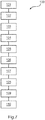
- Fig. 7 shows a diagram indicating method steps 101 to 110 of a method 100 for interacting with vessel images.
- the method 100 may be performed with a device 14 for interacting with vessel images or a system 10 for interacting with vessel images according to Fig. 1 .
- the method steps of Fig. 7 are described with references to Figs. 2a to 2h .
- the method is a computer-implemented method.
- the method comprises a step 101 of displaying the vessel image 24 on the display 21 of the device 14, as shown in Fig. 2a .
- a vessel contour 30 of the at least one vessel 26 in the vessel image 24 is determined, as shown in Fig. 2b .
- the determination may be performed with a processing unit 20.
- a further vessel contour 32 in the vessel image 24 may be determined.
- the further vessel contour 32 may be positioned opposite to the vessel contour 30 at the vessel 26.
- the vessel 26 may comprise a stenosis 28. As can be seen in Fig. 2b , the determined vessel contour 30 does not follow the stenosis 28. In this case, the method allows a user to correct the vessel contour 30.
- a touch position of a user input which is defined by the identifier position 36 in the vessel image 24 may be determined by the processor unit 20 via a touch controller 23 as shown in Fig. 2c .
- an indicating step 104 if the identifier position 36 is spaced apart from the vessel contour 30 by a distance 37 in the predefined distance range, at least a portion 38 of the vessel contour 30 in the vessel image 24 may be indicated, as shown in Fig. 2d .
- a drag interaction may be detected by the touch controller 23 and, in a further determining step 106, the drag direction 42 of the detected drag interaction may be determined by the processor unit 20. In an example, an angle between the drag direction and the currently indicated portion 38 of the vessel contour 30 is established.
- the processor unit 20 may increase a length of the indicated portion 38.
- the growth rate of the increase may be predefined and be chosen such that the user can accurately define the size of the indicated portion 38 on the vessel contour 30.
- a moving step 107 if the result of the angle determination is within a first predefined angle range 33, the indicated portion 38 of the vessel contour 30 will be moved along the vessel contour 30 by the processor unit 20.
- the movement follows the identifier, i.e. the user's finger, in the drag direction 42, as is shown in Fig. 2f .
- the user may drag his finger from the identifier position 36 to the position 40 in the vessel image 24.
- the vessel contour 30 may deform such that the indicated portion 38 will move 108 perpendicular to the earlier extension of vessel contour 30, as shown in Fig. 2g .
- the connection to the remaining vessel contour 30 is adapted to the movement of the indicated portion 38.
- the user may perform a further change of the drag movement into the direction 48 starting at the position 44, causing the indicated portion 38 of the deformed vessel contour 30 to move based on the direction 48, as shown in Fig. 2h .
- the final position and shape of the indicated vessel contour may be stored for subsequent use, for example, in a geometric or functional vessel analysis tool.
- a computer program or a computer program element 16 is provided that is characterized by being adapted to execute the method steps of the method according to one of the preceding embodiments, for example on an appropriate device as described with reference to Fig. 1 .
- the computer program element 16 might therefore be stored on a computer unit, which might also be part of an embodiment of the present invention.
- the computer program may be executed by the processing unit 20 of a device as described with reference to Fig. 1 .
- This computing unit may be adapted to perform or induce a performing of the steps of the method described above. Moreover, it may be adapted to operate the components of the above described apparatus. The computing unit can be adapted to operate automatically and/or to execute the orders of a user.
- a computer program may be loaded into a working memory of a data processor. The data processor may thus be equipped to carry out the method of the invention.
- This exemplary embodiment of the invention covers both, a computer program that right from the beginning uses the invention and a computer program that by means of an up-date turns an existing program into a program that uses the invention.
- the computer program element might be able to provide all necessary steps to fulfil the procedure of an exemplary embodiment of the method as described above.
- a computer readable medium 18, such as a CD-ROM is presented wherein the computer readable medium has a computer program element stored on it which computer program element 16 is described by the preceding section.
- a computer program may be stored and/or distributed on a suitable medium, such as an optical storage medium or a solid-state medium supplied together with or as part of other hardware, but may also be distributed in other forms, such as via the internet or other wired or wireless telecommunication systems.
- the computer program may also be presented over a network like the World Wide Web and can be downloaded into the working memory of a data processor from such a network.
- a medium for making a computer program element available for downloading is provided, which computer program element is arranged to perform a method according to one of the previously described embodiments of the invention.
Priority Applications (6)
| Application Number | Priority Date | Filing Date | Title |
|---|---|---|---|
| EP17306839.6A EP3503026A1 (fr) | 2017-12-20 | 2017-12-20 | Dispositif, système et procédé pour interagir avec des images de vaisseau |
| US16/955,824 US11409422B2 (en) | 2017-12-20 | 2018-12-11 | Device, system and method for interacting with vessel images |
| CN201880087133.3A CN111656402A (zh) | 2017-12-20 | 2018-12-11 | 用于与血管图像交互的设备、系统和方法 |
| JP2020534311A JP7356980B2 (ja) | 2017-12-20 | 2018-12-11 | 血管画像とインタラクトする装置、システム及び方法 |
| PCT/EP2018/084256 WO2019121128A1 (fr) | 2017-12-20 | 2018-12-11 | Dispositif, système et procédé d'interaction avec des images de vaisseau |
| EP18812188.3A EP3729372A1 (fr) | 2017-12-20 | 2018-12-11 | Dispositif, système et procédé d'interaction avec des images de vaisseau |
Applications Claiming Priority (1)
| Application Number | Priority Date | Filing Date | Title |
|---|---|---|---|
| EP17306839.6A EP3503026A1 (fr) | 2017-12-20 | 2017-12-20 | Dispositif, système et procédé pour interagir avec des images de vaisseau |
Publications (1)
| Publication Number | Publication Date |
|---|---|
| EP3503026A1 true EP3503026A1 (fr) | 2019-06-26 |
Family
ID=60954829
Family Applications (2)
| Application Number | Title | Priority Date | Filing Date |
|---|---|---|---|
| EP17306839.6A Withdrawn EP3503026A1 (fr) | 2017-12-20 | 2017-12-20 | Dispositif, système et procédé pour interagir avec des images de vaisseau |
| EP18812188.3A Pending EP3729372A1 (fr) | 2017-12-20 | 2018-12-11 | Dispositif, système et procédé d'interaction avec des images de vaisseau |
Family Applications After (1)
| Application Number | Title | Priority Date | Filing Date |
|---|---|---|---|
| EP18812188.3A Pending EP3729372A1 (fr) | 2017-12-20 | 2018-12-11 | Dispositif, système et procédé d'interaction avec des images de vaisseau |
Country Status (5)
| Country | Link |
|---|---|
| US (1) | US11409422B2 (fr) |
| EP (2) | EP3503026A1 (fr) |
| JP (1) | JP7356980B2 (fr) |
| CN (1) | CN111656402A (fr) |
| WO (1) | WO2019121128A1 (fr) |
Cited By (1)
| Publication number | Priority date | Publication date | Assignee | Title |
|---|---|---|---|---|
| CN112116615A (zh) * | 2019-11-19 | 2020-12-22 | 苏州润迈德医疗科技有限公司 | 根据血管中心线获取血管轮廓线的方法和装置 |
Citations (4)
| Publication number | Priority date | Publication date | Assignee | Title |
|---|---|---|---|---|
| DE10312193A1 (de) * | 2003-03-19 | 2004-09-09 | Siemens Ag | Verfahren zum Betreiben eines bildgebenden medizinischen Untersuchungsgeräts |
| EP2000894A2 (fr) * | 2004-07-30 | 2008-12-10 | Apple Inc. | Interfaces d'utilisateur graphique à base de mode pour dispositifs d'entrée tactiles |
| US20140146076A1 (en) | 2012-11-27 | 2014-05-29 | Samsung Electronics Co., Ltd. | Contour segmentation apparatus and method based on user interaction |
| WO2017117389A1 (fr) * | 2015-12-31 | 2017-07-06 | Acist Medical Systems, Inc. | Système et procédé de segmentation d'image semi-automatisée |
Family Cites Families (19)
| Publication number | Priority date | Publication date | Assignee | Title |
|---|---|---|---|---|
| US5583977A (en) * | 1993-10-21 | 1996-12-10 | Taligent, Inc. | Object-oriented curve manipulation system |
| WO2006137016A1 (fr) | 2005-06-21 | 2006-12-28 | Koninklijke Philips Electronics N. V. | Procede et dispositif destine a la production d'une image d'un vaisseau sanguin |
| CN101522105A (zh) | 2006-10-16 | 2009-09-02 | 皇家飞利浦电子股份有限公司 | 在手术室中执行台边自动脉管分析的方法 |
| EP2377095B1 (fr) * | 2008-12-10 | 2016-05-25 | Koninklijke Philips N.V. | Analyse de vaisseaux |
| EP2465094B1 (fr) * | 2009-08-12 | 2016-01-06 | Koninklijke Philips N.V. | Génération de données d objet |
| WO2014091328A1 (fr) | 2012-12-10 | 2014-06-19 | Koninklijke Philips N.V. | Règle numérique et réticule pour dénervation rénale |
| WO2014125492A1 (fr) * | 2013-02-13 | 2014-08-21 | Uzi Rahum | Dispositif, système et procédé permettant l'imagerie et le marquage d'un vaisseau sanguin |
| WO2014142468A1 (fr) * | 2013-03-13 | 2014-09-18 | Samsung Electronics Co., Ltd. | Procédé de fourniture d'une copie image et appareil à ultrasons associé |
| US11096668B2 (en) * | 2013-03-13 | 2021-08-24 | Samsung Electronics Co., Ltd. | Method and ultrasound apparatus for displaying an object |
| WO2014207139A1 (fr) * | 2013-06-28 | 2014-12-31 | Koninklijke Philips N.V. | Procédés d'utilisation d'informations de bruit d'image |
| US10387013B2 (en) * | 2013-10-07 | 2019-08-20 | Acist Medical Systems, Inc. | Systems and methods for controlled single touch zoom |
| US9406129B2 (en) | 2013-10-10 | 2016-08-02 | Medtronic, Inc. | Method and system for ranking instruments |
| WO2015197770A1 (fr) * | 2014-06-25 | 2015-12-30 | Koninklijke Philips N.V. | Dispositif d'imagerie pour l'enregistrement de différentes modalités d'imagerie |
| CN104809730B (zh) * | 2015-05-05 | 2017-10-03 | 上海联影医疗科技有限公司 | 从胸部ct图像提取气管的方法和装置 |
| KR101690655B1 (ko) | 2015-01-29 | 2016-12-28 | 삼성전자주식회사 | 의료 영상 처리 장치 및 의료 영상 처리 방법 |
| EP3359041B1 (fr) * | 2015-10-07 | 2021-03-03 | Koninklijke Philips N.V. | Simulation ffr mobile |
| TWI594206B (zh) * | 2016-01-08 | 2017-08-01 | Nat Yang-Ming Univ | Cardiac medical imaging single chamber mapping system and method |
| JP6809851B2 (ja) * | 2016-09-12 | 2021-01-06 | キヤノンメディカルシステムズ株式会社 | 医用画像診断装置及び医用画像処理装置 |
| WO2018133098A1 (fr) * | 2017-01-23 | 2018-07-26 | 上海联影医疗科技有限公司 | Procédé et système d'acquisition d'état de contrainte-déformation de paroi vasculaire |
-
2017
- 2017-12-20 EP EP17306839.6A patent/EP3503026A1/fr not_active Withdrawn
-
2018
- 2018-12-11 WO PCT/EP2018/084256 patent/WO2019121128A1/fr unknown
- 2018-12-11 CN CN201880087133.3A patent/CN111656402A/zh active Pending
- 2018-12-11 EP EP18812188.3A patent/EP3729372A1/fr active Pending
- 2018-12-11 US US16/955,824 patent/US11409422B2/en active Active
- 2018-12-11 JP JP2020534311A patent/JP7356980B2/ja active Active
Patent Citations (4)
| Publication number | Priority date | Publication date | Assignee | Title |
|---|---|---|---|---|
| DE10312193A1 (de) * | 2003-03-19 | 2004-09-09 | Siemens Ag | Verfahren zum Betreiben eines bildgebenden medizinischen Untersuchungsgeräts |
| EP2000894A2 (fr) * | 2004-07-30 | 2008-12-10 | Apple Inc. | Interfaces d'utilisateur graphique à base de mode pour dispositifs d'entrée tactiles |
| US20140146076A1 (en) | 2012-11-27 | 2014-05-29 | Samsung Electronics Co., Ltd. | Contour segmentation apparatus and method based on user interaction |
| WO2017117389A1 (fr) * | 2015-12-31 | 2017-07-06 | Acist Medical Systems, Inc. | Système et procédé de segmentation d'image semi-automatisée |
Cited By (3)
| Publication number | Priority date | Publication date | Assignee | Title |
|---|---|---|---|---|
| CN112116615A (zh) * | 2019-11-19 | 2020-12-22 | 苏州润迈德医疗科技有限公司 | 根据血管中心线获取血管轮廓线的方法和装置 |
| WO2021097817A1 (fr) * | 2019-11-19 | 2021-05-27 | 苏州润迈德医疗科技有限公司 | Procédé et appareil d'acquisition de lignes de contour d'un vaisseau sanguin en fonction d'une ligne centrale d'un vaisseau sanguin |
| CN112116615B (zh) * | 2019-11-19 | 2023-12-05 | 苏州润迈德医疗科技有限公司 | 根据血管中心线获取血管轮廓线的方法和装置 |
Also Published As
| Publication number | Publication date |
|---|---|
| US20200341622A1 (en) | 2020-10-29 |
| JP7356980B2 (ja) | 2023-10-05 |
| JP2021506473A (ja) | 2021-02-22 |
| US11409422B2 (en) | 2022-08-09 |
| EP3729372A1 (fr) | 2020-10-28 |
| WO2019121128A1 (fr) | 2019-06-27 |
| CN111656402A (zh) | 2020-09-11 |
Similar Documents
| Publication | Publication Date | Title |
|---|---|---|
| EP2465094B1 (fr) | Génération de données d objet | |
| US9974618B2 (en) | Method for determining an imaging specification and image-assisted navigation as well as device for image-assisted navigation | |
| US10387013B2 (en) | Systems and methods for controlled single touch zoom | |
| US9678620B2 (en) | Workflow for ambiguity guided interactive segmentation of lung lobes | |
| US9349220B2 (en) | Curve correction in volume data sets | |
| US11075003B2 (en) | Assistance apparatus for assisting interpretation report creation and method for controlling the same | |
| JP2024041755A (ja) | ディスプレイ上のマーカの正確な位置決め | |
| JP6430500B2 (ja) | 腫瘍の奏効測定を支援するための方法 | |
| US11099724B2 (en) | Context sensitive magnifying glass | |
| US11409422B2 (en) | Device, system and method for interacting with vessel images | |
| CN107463320B (zh) | 一种系统校正的方法及装置 | |
| JP7371136B2 (ja) | ポインティングデバイスの感度適応方法、コンピュータプログラム及び画像評価装置 | |
| JP6598565B2 (ja) | 画像処理装置、画像処理方法及びプログラム |
Legal Events
| Date | Code | Title | Description |
|---|---|---|---|
| PUAI | Public reference made under article 153(3) epc to a published international application that has entered the european phase |
Free format text: ORIGINAL CODE: 0009012 |
|
| AK | Designated contracting states |
Kind code of ref document: A1 Designated state(s): AL AT BE BG CH CY CZ DE DK EE ES FI FR GB GR HR HU IE IS IT LI LT LU LV MC MK MT NL NO PL PT RO RS SE SI SK SM TR |
|
| AX | Request for extension of the european patent |
Extension state: BA ME |
|
| RAP1 | Party data changed (applicant data changed or rights of an application transferred) |
Owner name: KONINKLIJKE PHILIPS N.V. |
|
| STAA | Information on the status of an ep patent application or granted ep patent |
Free format text: STATUS: THE APPLICATION IS DEEMED TO BE WITHDRAWN |
|
| 18D | Application deemed to be withdrawn |
Effective date: 20200103 |