EP3502534B1 - Verwendung eines spannrings mit einem spannabschnitt - Google Patents
Verwendung eines spannrings mit einem spannabschnitt Download PDFInfo
- Publication number
- EP3502534B1 EP3502534B1 EP17020582.7A EP17020582A EP3502534B1 EP 3502534 B1 EP3502534 B1 EP 3502534B1 EP 17020582 A EP17020582 A EP 17020582A EP 3502534 B1 EP3502534 B1 EP 3502534B1
- Authority
- EP
- European Patent Office
- Prior art keywords
- tensioning
- ring
- wedge
- guide member
- wedge element
- Prior art date
- Legal status (The legal status is an assumption and is not a legal conclusion. Google has not performed a legal analysis and makes no representation as to the accuracy of the status listed.)
- Active
Links
Images


Classifications
-
- F—MECHANICAL ENGINEERING; LIGHTING; HEATING; WEAPONS; BLASTING
- F16—ENGINEERING ELEMENTS AND UNITS; GENERAL MEASURES FOR PRODUCING AND MAINTAINING EFFECTIVE FUNCTIONING OF MACHINES OR INSTALLATIONS; THERMAL INSULATION IN GENERAL
- F16L—PIPES; JOINTS OR FITTINGS FOR PIPES; SUPPORTS FOR PIPES, CABLES OR PROTECTIVE TUBING; MEANS FOR THERMAL INSULATION IN GENERAL
- F16L33/00—Arrangements for connecting hoses to rigid members; Rigid hose-connectors, i.e. single members engaging both hoses
- F16L33/02—Hose-clips
-
- F—MECHANICAL ENGINEERING; LIGHTING; HEATING; WEAPONS; BLASTING
- F16—ENGINEERING ELEMENTS AND UNITS; GENERAL MEASURES FOR PRODUCING AND MAINTAINING EFFECTIVE FUNCTIONING OF MACHINES OR INSTALLATIONS; THERMAL INSULATION IN GENERAL
- F16L—PIPES; JOINTS OR FITTINGS FOR PIPES; SUPPORTS FOR PIPES, CABLES OR PROTECTIVE TUBING; MEANS FOR THERMAL INSULATION IN GENERAL
- F16L55/00—Devices or appurtenances for use in, or in connection with, pipes or pipe systems
- F16L55/16—Devices for covering leaks in pipes or hoses, e.g. hose-menders
- F16L55/162—Devices for covering leaks in pipes or hoses, e.g. hose-menders from inside the pipe
- F16L55/163—Devices for covering leaks in pipes or hoses, e.g. hose-menders from inside the pipe a ring, a band or a sleeve being pressed against the inner surface of the pipe
-
- F—MECHANICAL ENGINEERING; LIGHTING; HEATING; WEAPONS; BLASTING
- F16—ENGINEERING ELEMENTS AND UNITS; GENERAL MEASURES FOR PRODUCING AND MAINTAINING EFFECTIVE FUNCTIONING OF MACHINES OR INSTALLATIONS; THERMAL INSULATION IN GENERAL
- F16L—PIPES; JOINTS OR FITTINGS FOR PIPES; SUPPORTS FOR PIPES, CABLES OR PROTECTIVE TUBING; MEANS FOR THERMAL INSULATION IN GENERAL
- F16L55/00—Devices or appurtenances for use in, or in connection with, pipes or pipe systems
- F16L55/16—Devices for covering leaks in pipes or hoses, e.g. hose-menders
- F16L55/168—Devices for covering leaks in pipes or hoses, e.g. hose-menders from outside the pipe
- F16L55/17—Devices for covering leaks in pipes or hoses, e.g. hose-menders from outside the pipe by means of rings, bands or sleeves pressed against the outside surface of the pipe or hose
- F16L55/171—Devices for covering leaks in pipes or hoses, e.g. hose-menders from outside the pipe by means of rings, bands or sleeves pressed against the outside surface of the pipe or hose the ring or the sleeve being tightened by a wedge section
-
- F—MECHANICAL ENGINEERING; LIGHTING; HEATING; WEAPONS; BLASTING
- F16—ENGINEERING ELEMENTS AND UNITS; GENERAL MEASURES FOR PRODUCING AND MAINTAINING EFFECTIVE FUNCTIONING OF MACHINES OR INSTALLATIONS; THERMAL INSULATION IN GENERAL
- F16B—DEVICES FOR FASTENING OR SECURING CONSTRUCTIONAL ELEMENTS OR MACHINE PARTS TOGETHER, e.g. NAILS, BOLTS, CIRCLIPS, CLAMPS, CLIPS OR WEDGES; JOINTS OR JOINTING
- F16B2/00—Friction-grip releasable fastenings
- F16B2/02—Clamps, i.e. with gripping action effected by positive means other than the inherent resistance to deformation of the material of the fastening
- F16B2/04—Clamps, i.e. with gripping action effected by positive means other than the inherent resistance to deformation of the material of the fastening internal, i.e. with spreading action
-
- F—MECHANICAL ENGINEERING; LIGHTING; HEATING; WEAPONS; BLASTING
- F16—ENGINEERING ELEMENTS AND UNITS; GENERAL MEASURES FOR PRODUCING AND MAINTAINING EFFECTIVE FUNCTIONING OF MACHINES OR INSTALLATIONS; THERMAL INSULATION IN GENERAL
- F16B—DEVICES FOR FASTENING OR SECURING CONSTRUCTIONAL ELEMENTS OR MACHINE PARTS TOGETHER, e.g. NAILS, BOLTS, CIRCLIPS, CLAMPS, CLIPS OR WEDGES; JOINTS OR JOINTING
- F16B2/00—Friction-grip releasable fastenings
- F16B2/02—Clamps, i.e. with gripping action effected by positive means other than the inherent resistance to deformation of the material of the fastening
- F16B2/14—Clamps, i.e. with gripping action effected by positive means other than the inherent resistance to deformation of the material of the fastening using wedges
-
- H—ELECTRICITY
- H02—GENERATION; CONVERSION OR DISTRIBUTION OF ELECTRIC POWER
- H02G—INSTALLATION OF ELECTRIC CABLES OR LINES, OR OF COMBINED OPTICAL AND ELECTRIC CABLES OR LINES
- H02G3/00—Installations of electric cables or lines or protective tubing therefor in or on buildings, equivalent structures or vehicles
- H02G3/22—Installations of cables or lines through walls, floors or ceilings, e.g. into buildings
Definitions
- the present invention relates to a clamping ring with a clamping section.
- a clamping ring of the type in question can be used, for example, in a wall or floor lead-through, for example to press a soft, flexible sleeve onto a relatively stiffer line or pipe element.
- the circumference of the clamping ring can be changed by tightening a clamping screw, with which the clamping ring is pressed in directions perpendicular to the ring axis, in order to then, for example, press the elastomer or rubber sleeve against the pipe element with increasing pressure.
- the present invention is based on the technical problem of specifying a particularly advantageous clamping ring as the subject of use.
- the tensioning section of the tensioning ring has a wedge element and a guide part.
- the wedge element is guided on the guide part and can be moved along a movement path in this guide by tightening the clamping screw.
- This movement distance is proportionately in a width direction in which the width of the clamping section is taken.
- the wedge element and the guide part are held together in a form-fitting manner in relation to the width direction, namely, they engage with one another with an undercut.
- the form-fitting cohesion of the wedge element and the guide part can advantageously expand the application possibilities of the clamping ring, because it also allows narrowing (reducing the width).
- a form fit is such that the wedge element and the guide part are guided to one another in a form-fitting manner not only when the clamping section or clamping ring is narrowed, but also when widening.
- the idea of the invention can generally also be implemented, for example, with two L-profiles that hooked together form the undercut, one of the two parts preferably also provides a guide surface in the opposite direction.
- a corresponding clamping ring can thus be used or designed both for pressing radially outward (away from the ring axis) and, but not according to the invention, for pressing radially inward (towards the ring axis).
- the undercut or the form-fitting arrangement sometimes increase the effort in design and manufacture, the advantages nevertheless outweigh the disadvantages.
- the undercut between the wedge element and the guide part is viewed in a plane of section perpendicular to the ring axis.
- the "ring axis" is generally that center axis of the ring shape around which the circumference of the clamping ring is taken.
- the clamping ring can, for example, be rotationally symmetrical about the ring axis at least in sectors.
- the width direction is perpendicular to the ring axis; with a change in the size ("width") of the clamping section taken in the width direction, the circumference around the ring axis changes accordingly.
- “axial”, “radial” and “circumferential”, as well as the corresponding directions refer to the ring axis without expressly stated otherwise.
- “Inside” and “outside” refer to the radial directions with the ring axis as the center or line, unless expressly stated otherwise.
- the wedge element can be moved along a movement path on the guide part
- this of course refers to the guide part as a "stationary" reference system.
- the guide part would be moved relative to it.
- the guide part In relation to the rest of the clamping ring (apart from the clamping section), the guide part preferably rests and the wedge element is moved.
- a movement path with a (slight) curvature is generally also conceivable, which would not only result in a (partial) offset in the width direction, but at the same time also a (slight) relative tilting of the wedge element and guide part, a straight movement path is preferred.
- the wedge element and the guide part are therefore preferably guided to one another in the manner of a linear bearing, particularly preferably in the manner of a linear plain bearing (this can be far less expensive than a ball or roller bearing design, which is generally also conceivable).
- one advantage of the clamping section with the wedge element can be that it has a comparatively robust structure on the one hand, which can be advantageous, for example, on a construction site, but also generally in practice.
- a desired "transmission ratio" can be set comparatively easily in the design by adapting the angle between the movement path and the width direction. For example, with a small angle the offset (in the width direction) is large, but the force transmission (and accordingly a pressure force that can be generated) is small, and vice versa with a large angle (see also below in detail).
- the clamping screw is aligned with its axis of rotation essentially parallel to the ring axis, that is, tilted by no more than 10 °, 5 ° or 2 ° in relation to it (increasingly preferred in the order in which they are named).
- the smaller of the two angles that the two axes enclose with each other is considered here.
- the ring axis and the axis of rotation are parallel to one another (0 °) within the scope of the technically usual accuracy.
- the movement path of the wedge element is made up of the portion in the width direction and a portion perpendicular to it, which is then parallel to the axis of rotation of the clamping screw.
- this "axial" orientation of the clamping screw can be advantageous insofar as it can be screwed from one end face during assembly.
- the inventors have found that otherwise, if, for example, a screwdriver as in the case of a tensioning clip has to be placed radially or from a circumferential direction on the tensioning screw, the space available is often restricted, i.e. accessibility is poor.
- the clamping ring can, for example, be placed on a pipe element that protrudes from a wall (e.g. a building wall, but also housing wall, etc.), in which case screwing is difficult if the clamping ring is to be placed close to the wall surface .
- the tension ring has a tension band. This forms a section or a segment in relation to a revolution around the ring axis; it can extend, for example, over an angle of at least 30 °, 50 °, 70 °, 90 °, 100 ° or 110 °.
- the tensioning strap can also extend completely circumferentially apart from the tensioning section or the wedge element, but on the other hand, for example, modular structures with several tensioning straps or sections are also conceivable (see in detail below) and can have possible upper limits at a maximum of 170 °, 150 ° or 130 °.
- the tensioning band can preferably have the shape of a flat strip, that is to say, taken along the ring axis (“axially”), a greater extent than perpendicular to the ring axis (“radially”).
- the ratio of axial to radial extension can, for example, at least 2: 1, 3: 1, 4: 1 or 5: 1, with possible upper limits (regardless of this) being at most 100: 1, 80: 1, 60: 1, 40: 1 or 20: 1 can.
- this can also depend on the material, so that, for example, in the case of a tensioning strap made of plastic, for example made of polyamide (e.g.
- the upper limits can be lower, for example at most 10: 1, 8: 1, 6: 1 or 5: 1, and low lower limits are also conceivable, for example at least 1: 2 or 1: 1 (the ratio of axial to radial extent is specified in each case).
- the guide part is arranged on a joint end of the tensioning strap.
- the tensioning band does not extend circumferentially beyond the tensioning section, so it does not cover the wedge element radially inwards or outwards.
- the tensioning strap and the guide part can be provided in several parts relative to one another, so they can be put together as before in each case separately manufactured components; The tensioning band and guide part can then, for example, be or be screwed or riveted together, cf. also Fig. 6 for illustration.
- the tensioning strap is made of metal, in particular as a metal strip (cf. the above information on the "strip shape").
- the tensioning band itself then preferably forms the guide part and for this purpose it is bent over at the joint end.
- the joint end itself can also lie in the plane or surface of the rest of the tensioning strap, so for example an axially extending bead can be bent into the strap at the joint end.
- the joint end itself is preferably bent out, either bent radially inward or bent out radially outward.
- the integration of the tension band and guide part can help reduce the number of components, i.e. reduce the complexity during assembly, which can be particularly advantageous in mass production. Furthermore, a corresponding bending on or out of the joint end is also well controlled per se and can be reproduced in production.
- the guide part engages in a recess in the wedge element to form the undercut, so the guide part represents a male and the wedge element a female form-locking element In the width direction and also in the opposite direction, the form fit exists both when narrowing and when expanding the clamping section or clamping ring.
- the female form-locking element thus guides the male element, regardless of the direction in which the clamping screw is turned.
- the female form-locking element surrounds the male element, or at least a section thereof, radially inward and at the same time radially outward, which, for example, can prevent undesirable "popping open” during assembly or under load.
- the wedge element preferably forms the female form-locking element in which the guide part is received (with regard to the width direction and in the opposite direction, and preferably also radially inwards and at the same time radially outwards).
- the guide part has the shape of an L-profile, that is to say it is L-shaped when viewed in sectional planes perpendicular to the movement path.
- One leg of the L-profile which extends radially inward or outward from the other leg, then forms the undercut.
- the other leg of the L-profile then preferably merges into the wedge element without offset, so there is no offset between said leg and a radially inwardly facing inner wall surface of the wedge element or its radially outwardly facing outer wall surface, at least within the scope of technically possible and customary fits.
- the guide part can enter the wedge element on a peripheral side of the wedge element at the radially inner edge (without offset with inner wall surface) or the radially outer edge (without offset with outer wall surface).
- a corresponding configuration can be advantageous, for example, as a clamping ring designed to be pressed radially inward with an at least largely smooth inner wall or a clamping ring designed to be pressed radially outward with an at least largely smooth outer wall.
- a clamping ring designed to be pressed radially inward with an at least largely smooth inner wall
- a clamping ring designed to be pressed radially outward with an at least largely smooth outer wall.
- even power transmission is supported when the clamping ring is pressed on, which can be used to prevent local excessive force increases, for example. If, for example, an elastomer or rubber sleeve is pressed on, local overstressing of the elastomer material can be prevented.
- the offset-free design can also help prevent undesirable creepage paths for moisture and, accordingly, leaks.
- the movement path forms an acute angle on the guide part side with an end face of the clamping ring, that is to say an angle of less than 90 °.
- the angle can, for example, be at most 80 ° or 75 °, with possible (independent) lower limits at, for example, at least 10 ° or 15 °.
- face means an axial face; in concrete terms, then, in the present case, that of the two axially opposite end faces to which the wedge element is moved during or for widening is in question.
- a recess delimited in the direction of rotation by the guide part, in which the wedge element is arranged and guided opens axially outward.
- a clamping section with a further wedge element which is guided axially opposite the first on a further guide part along a further movement path can then, viewed radially, the two guide parts or the joint end of the tensioning strap have or form a dovetail shape.
- the movement path includes an angle of at least 15 °, more and more preferably at least 25 ° or 30 ° with an axial direction parallel to the ring axis.
- Advantageous upper limits which in general can also be of interest and should be disclosed independently of the lower limits, are, in the order in which they are mentioned, increasingly preferably at most 75 °, 65 ° or 60 °. The smaller of the two angles that enclose the movement path and said direction with one another (and which add up to 180 °) is considered.
- the movement path can also enclose an obtuse angle with the end face.
- the recess delimited by the guide part then widens axially outward.
- that face is considered to which the wedge element is moved in order to reduce the width of the clamping section or the circumference of the clamping ring.
- the clamping screw can preferably have a right-hand thread, that is to say a thread rising to the right.
- a clamping screw that is available as standard and accordingly also inexpensive can be used.
- the clamping ring is preferably provided in such a way that, insofar as it is designed in particular for pressing radially inward or outward, the corresponding narrowing (pressing inward), which does not represent a use according to the invention, or widening (pressing outward) with a clockwise rotation of the Clamping screw can be achieved. This can be intuitively easy to handle for a fitter. This can now be achieved independently of the orientation of the movement path by using a clamping screw with a left or right thread if necessary.
- a clamping ring designed to be pressed radially inward is preferred with an acute angle between Movement path and face (on the guide part side) included.
- an obtuse angle may be preferred; If the wedge element moves axially inwards when the clamping screw with a right-hand thread is tightened (clockwise), the guide part is pushed away in the direction of rotation, i.e. the width increases.
- the wedge element is double-wedge-shaped, which relates to the width or circumferential direction.
- the double wedge is therefore guided on one side of the circumference on the first guide part and on the opposite side of the circumference on a second guide part along a second movement path. Since it is a double wedge, this second movement path is also tilted with respect to the axial direction, so there is a movement component in the width direction.
- a wedge element would also be conceivable, for example, which is only guided obliquely to the axial direction on one circumferential side and exclusively axially on the other, so that there is no change in width with the movement in the axial direction.
- the two inclined movement paths are aligned relative to one another in such a way that the respective changes in width add up, that is, have the same sign (regardless of whether it is an increase or a decrease).
- the two movement paths preferably enclose angles of equal size with the axial direction;
- the movement paths are preferably mirror-symmetrical to a mirror plane containing the ring axis.
- the double wedge itself is also preferably constructed in a mirror-symmetrical manner, at least with regard to its guide surfaces, along which it slides on the guide parts, preferably to a mirror plane containing the ring axis.
- the guide parts are preferably constructed mirror-symmetrically to one another in their guide surfaces on which the double wedge is guided (with respect to the mirror plane containing the ring axis).
- the second guide part and the double wedge also engage with one another in a form-fitting manner with an undercut (in relation to the width direction or in opposite directions).
- the double wedge is provided in several parts, namely composed of a first and a second double wedge part.
- the double wedge is therefore in particular not designed as a monolithic part formed continuously from the same material, but rather from at least two, preferably exactly two parts.
- the first double wedge part is guided on the first guide part, the second double wedge part on the second guide part, which is in several parts to the first double wedge part.
- the multi-part structure can be advantageous, for example, as it can simplify the assembly, i.e. the threading or threading of the double wedge into or onto the guide parts, in particular with relatively large gear ratios, i.e. relatively far tilted movement paths.
- the double wedge parts can then initially be placed individually on the respective guide part (in their guide) in order to then be connected to one another.
- the clamping screw penetrates the first and the second double wedge part.
- the tensioning screw which is already provided for tensioning, is advantageously used twice, which can help reduce the number of individual parts and reduce complexity. In general, however, it would also be conceivable to connect the first and the second double wedge part in some other way, for example to screw or rivet them with a separate screw.
- the clamping section has a further wedge element axially opposite the first wedge element. This is guided on a further guide part, also along a movement path that has a share in the width direction.
- the movement path of the first wedge element and that of the further wedge element preferably have an equal share in the width direction, which results in an even widening or narrowing and thus pressure.
- the screw head of the clamping screw can abut on one wedge element (at least indirectly, for example also with a washer in between), the thread of the clamping screw acts on the other wedge element.
- the latter can be done indirectly, for example by means of a nut placed separately on the wedge element.
- the thread preferably acts directly on said wedge element, for example a corresponding thread can be made in the wedge element.
- the latter is not mandatory, for example a self-tapping clamping screw could also be used in a plastic wedge element (the wedge element would then sometimes have no or at least no opening with a pre-assembled internal thread).
- the further wedge element is preferably constructed analogously to the first wedge element, in particular as a double wedge, in particular in several parts.
- the first and the further wedge element are preferably mirror-symmetrical in terms of their movement paths with respect to a mirror plane perpendicular to the ring axis, which extends axially through the clamping ring. With regard to said plane, the guide parts of one wedge element are preferably also mirror-symmetrical to those of the other.
- the first and the further wedge element are preferably structurally identical to one another, in any case apart from the opening or openings for the clamping screw (these are usually introduced by mechanical reworking).
- a second wedge element is not mandatory, the clamping screw could, for example, also be supported on a rail fixed on the clamping ring, with any relative offset of the wedge element in the circumferential direction via an elongated hole.
- a production of the wedge element in a molding process can be preferred, in which a molding tool releases the wedge element (in its final shape, at least by a normal mechanical post-processing).
- the wedge element is made from plastic, for example, from polyamide, in particular glass fiber reinforced polyamide, it can be manufactured by injection molding.
- the wedge element is made of a metal, a metal casting or investment casting is possible, for example also an aluminum die casting.
- a nut for the clamping screw
- additive manufacturing is conceivable for both plastic and metal, i.e. using 3D printing, which can be of interest due to the accessibility of more complex geometries.
- laser sintering would be an option.
- the clamping ring has a plurality of clamping sections distributed over the circumference. In total, at least two clamping sections are then provided, but at least three or at least four clamping sections are also possible, for example. Upper limits can, for example, be at most 10, 8 or 6 clamping sections. In particular in the case of a modular structure (see below), however, far more clamping sections are also possible and upper limits can be, for example, at most 30, 25 or 20 clamping sections. Regardless of their number, the clamping sections are not necessarily evenly distributed over the circumference, but this can be preferred with regard to the most uniform possible distribution of the pressing force.
- the positions of the clamping sections can then, in particular, be rotationally symmetrical to one another about the ring axis, and preferably even the clamping sections can also be rotationally symmetrical to one another (not just their positions).
- the clamping ring has several clamping ring segments.
- a first and a second clamping ring segment are held together in a form-fitting manner in relation to the direction of rotation (around the ring axis), that is to say with an undercut.
- the first and second clamping ring segments do not serve to change the width / circumference, but rather have a modular structure.
- the form fit is provided in such a way that the first and the second clamping ring segment either cannot be axially displaced relative to one another or any relative displacement does not change the extent of the assembled segments in the circumferential direction.
- the clamping ring segments can, for example, interlock in a manner comparable to a T-profile.
- the one clamping ring segment is then preferably designed as a male form-locking element on the corresponding circumferential side, and the other clamping ring segment on the facing circumferential side as a female form-locking element.
- each of the clamping ring segments provides both a male and a female form-locking element at the connection point, that is, they are complementary to one another in pairs. Assembling by axially sliding one into the other would still be possible if, for example, each of the segments were divided into two with respect to the axial direction.
- Each of the segments is preferably provided in one piece / monolithic, which can be of interest with regard to an overall simple structure.
- the clamping ring segments can preferably be provided from a plastic, for example a glass fiber reinforced plastic, such as, for example, glass fiber reinforced polyamide.
- the wedge element and / or the guide part made of plastic can then preferably also be provided.
- a correspondingly modularly constructed clamping ring made of metal parts is also conceivable, which can then be produced, for example, by die casting or, in particular, with regard to more complex geometries, also by generative construction, for example by laser sintering.
- the first and the second clamping ring segment can then either again be "neutral" or be designed to guide a wedge element on their circumferential side opposite the respective connection point.
- the invention also relates to a set of several clamping rings which are structurally identical to one another with regard to their clamping sections.
- the clamping rings can, however, differ in a circumferential length of the respective clamping bands used in the direction of rotation. Different clamping rings can therefore be realized with the same, structurally identical clamping section by using clamping bands of different lengths (see above).
- This modular principle opens up a variability, whereby the clamping section, which is usually more complex than the rest of the clamping ring, does not have to be specially adapted.
- the clamping rings of a corresponding set can also be gripped with the clamping ring segments described above, with clamping ring segments of the same construction preferably being found in the clamping rings, but in different numbers. For example, a larger number of "neutral" clamping ring segments can be used to create a larger clamping ring.
- the invention relates to the use of a clamping ring disclosed in the present case for pressing radially outwards.
- An inventive clamping ring can be used for a Pressing can be provided in both directions, but on the other hand it can also be specially designed for pressing outwards, cf. also the exemplary embodiment for illustration.
- the clamping ring is preferably pressed against a tubular element, that is to say against its inner wall surface (whereby it does not have to rest against said surface, but in any case presses against it, that is to say is pressed against it).
- the ring axis can then preferably coincide with a longitudinal axis of the tubular element (about which it is typically rotationally symmetrical) and / or a longitudinal axis of the line (the length of the line is taken along the longitudinal axis).
- the pipe element can in particular be part of an entry or lead-through with which a line is brought through a wall or floor element.
- the line can be, for example, a cable or a media pipe, while the lead-through can be a wall lead-through; If this is designed for a building wall, the tubular element can be structurally integrated into this building wall, for example embedded in concrete.
- the clamping ring can in particular be used to press on a body which is softer in relation to the tubular element and which is at least partially sleeve-shaped, but can also have a complex structure overall. With the clamping ring, the (softer) sleeve is then pressed against the (harder) pipe element, against the inner wall surface.
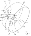
- Fig. 1 shows a clamping ring 1 for use according to the invention in an oblique view, that is, looking at it obliquely to a ring axis 2.
- the clamping ring 1 has a clamping section 3 whose width taken in a width direction 4 can be changed by tightening a clamping screw 5.
- the clamping section 3 has a wedge element 6 which is movably guided on guide parts 7a, b.
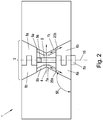
- the wedge element 6 is guided on the respective guide part 7a, b such that it can move along a movement path 20a, b. How out Fig. 2
- the movement paths 20a, b each also have a portion in the width direction 4, so that the width of the clamping section 3 also changes with the axial displacement of the wedge element 6.
- a thread 5a of the clamping screw 5 is provided as a right-hand thread, so that the wedge element 6 is moved in the direction of the axial center of the clamping ring 1 when the clamping screw 5 is tightened (clockwise turning on the screw head 5b).
- the guide parts 7a, b are pressed apart, the circumference of the clamping ring 1 increases.
- the clamping ring 1 shown here can therefore be used in particular for pressing radially outwards. It can, for example, be placed in a rubber or elastomer sleeve and arranged together with this in a pipe element; by tightening the clamping screw 5, the circumference of the clamping ring 1 is expanded and the collar is pressed against the inner wall surface of the tubular element.
- the clamping section 3 has a further wedge element 8 which is also guided on guide parts 9a, b.
- the corresponding movement paths are in turn inclined to the ring axis 2 or axis of rotation 15 of the clamping screw 5, but are shown in FIG Fig. 2 not shown.
- the wedge elements 6, 8 are each constructed in several parts, namely each of a first double wedge part 6a, 8a and a second double wedge part 6b, 8b.
- the double wedge parts 6a, b, 8a, b are first threaded onto their respective guide parts 7a, b, 9a, b, cf. also the axial view according to Fig. 3 for illustration.
- the multi-part structure of the wedge elements 6, 8 simplifies this threading.
- the wedge elements 6, 8 are then each put together, that is to say the double wedge parts 6a, b and 8a, b are pushed into one another in the direction of rotation.
- the clamping screw 5 is inserted, which then penetrates and holds together both double wedge parts 6a, b and 8a, b for each wedge element 6, 8.
- the present clamping ring 1 forms over its essential circumference a clamping band 30 made of metal is provided. Specifically, it is a sheet of steel that is bent into a ring shape. The butt ends 30a, b of the tensioning strap 30 are bent radially inward, so the tensioning strap 30 itself forms the guide parts 7a, b (or also 9a and 9b).
- the wedge elements 6, 8 with the respective guide parts 7, 9 are each positively held together with an undercut (in relation to the width direction 4).
- the wedge elements 6, 8 are thus guided on the guide parts 7, 9, regardless of whether the clamping ring is widened (in Fig. 2 by tightening the clamping screw 5 and moving the wedge elements 6, 8) towards each other or is tapered.
- the wedge elements 6, 8 can pull the guide parts 7a and 7b or 9a and 9b towards one another in the width direction 4.
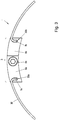
- Fig. 4 shows the same clamping ring as the one again Figs. 1 to 3 , but in a view from the inside to the outside, that is, away from the ring axis 2 to the radially outside.
- the guide parts 7a, b, 9a, b are shaped by bending the tensioning strap 30 radially inward, that is to say towards the viewer. The gaze falls in Fig. 4 onto the butt ends of the tension band 30.
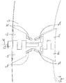
- Fig. 5 shows another clamping ring 1, which is largely comparable to the clamping ring 1 discussed so far.
- the same reference symbols denote parts with the same or essentially the same function.
- the main difference lies in the orientation of the movement paths 20a, b.
- the guide formed by the guide parts therefore tapers axially outward.
- the angle 50 is obtuse, correspondingly the guide expands axially outward.
- the clamping ring 1 can be designed in such a way that it is either widened when the clamping screw 5 with a right-hand thread is tightened (clockwise) ( Fig. 2 ) or is narrowed ( Fig. 5 ), both are then possible with a clockwise rotation.
- the guide parts 7a, b are placed on the tensioning strap 30 as separate elements.
- the guide parts 7a, b are fastened to the tensioning strap 30 with a respective rivet 60a, b, but, alternatively, screwing or the like would also be conceivable, for example.
- the tensioning section 3 can also be assembled first before the guide parts 7a, b are attached to the tensioning strap 30. A simplified threading would then also be possible without dividing the wedge element 6 into two.
- the variant according to Fig. 6 also differs in this respect from that according to Fig. 3 , as the L-profiles of the guide parts 7a, b are not oriented radially inward, but radially outward. Accordingly, in the variant according to Fig. 6 the radially inner wall surface of the wedge element 6 smoothly or offset-free into the respective lying leg of the L-profile (not into the respective outwardly directed leg).
- the clamping ring 1 according to Fig. 6 is therefore particularly suitable for pressing inwards, because there it enables a uniform transmission of the pressing force.
- the variant according to Fig. 6 is therefore particularly suitable for pressing inwards, because there it enables a uniform transmission of the pressing force.
- the respective lying leg of the L-profile merges smoothly into the radially outwardly facing wall surface of the wedge element 6, which is why this clamping ring is particularly suitable for pressing radially outward. Even if the clamping ring is specially designed to be pressed inwards or outwards, it can be advantageous, for example, during dismantling / revision, if it is also held together positively in the opposite direction.
- the tensioning band 30 is an injection-molded plastic ring made of glass fiber reinforced polyamide.
- the guide parts 7a, b are in turn provided at their butt ends 30a, b, in this case as female form-locking elements.
- the wedge element 6 forms male form-locking elements, T-shaped in section, which engage in the pockets of the guide parts 7a, b and are held in a form-locking manner.
- the pockets can already be taken into account in the clamping ring 30 during injection molding.
- the wedge elements 6, 8 can be made of metal, or else they can be injection molded from plastic (in particular from glass fiber reinforced polyamide), also in combination with a metal tensioning strap.
- the variant differs in its functionality according to Fig. 7 not of the concepts discussed so far, the wedge element 6 and (the one in Fig. 7 wedge elements 8) arranged behind it are moved towards each other by tightening the clamping screw 5, whereby, depending on the orientation of the movement paths (obtuse or acute angle, see above), the width either increases or decreases.
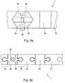
- Fig. 8 shows a further clamping ring 1 in a schematic view, which, in contrast to the variant according to FIG Fig. 1 not only one clamping section 3, but a total of three clamping sections 3a, b, c. In the present case, these are distributed equidistantly over the circuit 80, which results in a uniform distribution of the contact pressure.
- the clamping ring shown schematically is designed to be pressed radially inward, but a clamping ring 1 with multiple bracing (several clamping sections) can also be implemented with each of the variants discussed above.
- FIGs 9a, b show a modular clamping ring 1 or a section thereof. It shows Figure 9a a view looking radially inward, and Figure 9b an axial view. Like the variants discussed so far, this clamping ring 1 also has a clamping section 3 with wedge elements 6, 8 and corresponding ones Guide parts 7, 9. In this respect, reference is made in particular to the explanations Fig. 7 referenced.
- the clamping ring 1 according to Figures 9a, b but is also made up of modules, it has a first 90 and second clamping ring segment 91. These also interlock in a form-fitting manner, but this form-fitting only serves to hold together in the circumferential direction.
- the first 90 and the second clamping ring segment 91 could be axially displaced relative to one another, but this would not change the width in the circumferential direction.
- the second double wedge part 6b is guided at an angle analogously to the above description (for width adjustment).
Landscapes
- Engineering & Computer Science (AREA)
- General Engineering & Computer Science (AREA)
- Mechanical Engineering (AREA)
- Architecture (AREA)
- Civil Engineering (AREA)
- Structural Engineering (AREA)
- Clamps And Clips (AREA)
Priority Applications (9)
| Application Number | Priority Date | Filing Date | Title |
|---|---|---|---|
| ES17020582T ES2839324T3 (es) | 2017-12-19 | 2017-12-19 | Uso de un anillo tensor con una sección tensora |
| EP17020582.7A EP3502534B1 (de) | 2017-12-19 | 2017-12-19 | Verwendung eines spannrings mit einem spannabschnitt |
| CN201880082854.5A CN111492167A (zh) | 2017-12-19 | 2018-12-18 | 具有锁紧区段的锁紧环 |
| PCT/EP2018/085411 WO2019121627A1 (de) | 2017-12-19 | 2018-12-18 | Spannring mit einem spannabschnitt |
| JP2020533603A JP7315174B2 (ja) | 2017-12-19 | 2018-12-18 | 締め付け部を有する締め付けリング |
| KR1020207020438A KR102668486B1 (ko) | 2017-12-19 | 2018-12-18 | 클램핑 섹션을 구비한 클램핑 링 |
| NZ765714A NZ765714B2 (en) | 2018-12-18 | Tensioning ring with a tensioning section | |
| US16/955,360 US11333279B2 (en) | 2017-12-19 | 2018-12-18 | Tensioning ring with a tensioning section |
| AU2018387201A AU2018387201B2 (en) | 2017-12-19 | 2018-12-18 | Tensioning ring with a tensioning section |
Applications Claiming Priority (1)
| Application Number | Priority Date | Filing Date | Title |
|---|---|---|---|
| EP17020582.7A EP3502534B1 (de) | 2017-12-19 | 2017-12-19 | Verwendung eines spannrings mit einem spannabschnitt |
Publications (2)
| Publication Number | Publication Date |
|---|---|
| EP3502534A1 EP3502534A1 (de) | 2019-06-26 |
| EP3502534B1 true EP3502534B1 (de) | 2020-12-02 |
Family
ID=60781443
Family Applications (1)
| Application Number | Title | Priority Date | Filing Date |
|---|---|---|---|
| EP17020582.7A Active EP3502534B1 (de) | 2017-12-19 | 2017-12-19 | Verwendung eines spannrings mit einem spannabschnitt |
Country Status (8)
| Country | Link |
|---|---|
| US (1) | US11333279B2 (enExample) |
| EP (1) | EP3502534B1 (enExample) |
| JP (1) | JP7315174B2 (enExample) |
| KR (1) | KR102668486B1 (enExample) |
| CN (1) | CN111492167A (enExample) |
| AU (1) | AU2018387201B2 (enExample) |
| ES (1) | ES2839324T3 (enExample) |
| WO (1) | WO2019121627A1 (enExample) |
Families Citing this family (3)
| Publication number | Priority date | Publication date | Assignee | Title |
|---|---|---|---|---|
| DE102021105652A1 (de) * | 2021-03-09 | 2022-09-15 | Ruhr-Universität Bochum, Körperschaft des öffentlichen Rechts | Federbandschelle und Verfahren zu deren Herstellung |
| AT525567B1 (de) * | 2022-01-13 | 2023-05-15 | Henn Gmbh & Co Kg | Rohrpresskupplung |
| WO2024068557A1 (de) | 2022-09-26 | 2024-04-04 | Hauff-Technik Gmbh & Co. Kg | Verwendung einer elastomerhülse zur montage auf einer leitung |
Family Cites Families (21)
| Publication number | Priority date | Publication date | Assignee | Title |
|---|---|---|---|---|
| US201603A (en) * | 1878-03-26 | Improvement in barrels | ||
| US2474062A (en) * | 1946-01-21 | 1949-06-21 | Gerald E Murphy | Clamping ring |
| US2803866A (en) * | 1953-06-29 | 1957-08-27 | Tinnerman Products Inc | Band clamp with axial manipulating means |
| US2778085A (en) * | 1955-05-23 | 1957-01-22 | Aeroquip Corp | Band clamp of the axially operable type |
| US2855167A (en) * | 1955-10-03 | 1958-10-07 | Aeroquip Corp | Axially operating clamp |
| US2922212A (en) * | 1957-04-30 | 1960-01-26 | Hoffman Electronics Corp | Clamp apparatus or the like |
| FR2076554A5 (enExample) * | 1970-01-20 | 1971-10-15 | Ghionzoli Jacques | |
| US3769665A (en) * | 1972-08-30 | 1973-11-06 | Breeze Corp | Variable length tangential worm driven clamp |
| JPS58130191U (ja) | 1982-02-26 | 1983-09-02 | 加藤発条株式会社 | ホ−スクランプ |
| US5024404A (en) * | 1987-10-19 | 1991-06-18 | Ballard Estus E | Pipe clamp for overhead sprinkler heads and the like |
| CA2052984C (en) * | 1991-02-08 | 2002-08-13 | William P. Gundy | Band with slotted wedge cams |
| US5431459A (en) * | 1991-02-08 | 1995-07-11 | Npc, Inc. | Band with slotted wedge cams |
| US6394505B1 (en) * | 2000-07-24 | 2002-05-28 | Geberit Technik | Connection between the intake end of a discharge pipe and the outlet end of a connection curve of a water toilet |
| US6641176B2 (en) * | 2001-04-03 | 2003-11-04 | Ncp, Inc. | Wide clamping band for clamping a connector boot within a hole through a generally cylindrical wall |
| JP2003074079A (ja) | 2001-08-31 | 2003-03-12 | Sankei Giken:Kk | 継手圧着具 |
| US7146689B2 (en) * | 2002-10-25 | 2006-12-12 | Press-Seal Gasket Corporation | Expansion ring assembly |
| DE10323159A1 (de) * | 2003-05-22 | 2004-12-23 | Gk-System Gmbh | Vorrichtung und Verfahren zur Abdichtung in Durchbrüchen mit einer elektromagnetischen Abschirmung |
| CA2511408C (en) | 2004-07-06 | 2009-06-23 | Press-Seal Gasket Corporation | Expansion ring assembly |
| US7765650B2 (en) * | 2007-05-21 | 2010-08-03 | Epicor Industries, Inc. | Two-piece hose clamp and variable length clamp kit |
| IL191447A (en) * | 2008-05-14 | 2012-01-31 | Eliezer Krausz | Pipe clamp with self-aligning mechanism while closing of same |
| KR101223090B1 (ko) * | 2012-10-05 | 2013-01-17 | 극동일렉콤주식회사 | 전자파 차폐를 위한 멀티 케이블 트랜시트용 엔드패킹 |
-
2017
- 2017-12-19 ES ES17020582T patent/ES2839324T3/es active Active
- 2017-12-19 EP EP17020582.7A patent/EP3502534B1/de active Active
-
2018
- 2018-12-18 AU AU2018387201A patent/AU2018387201B2/en active Active
- 2018-12-18 KR KR1020207020438A patent/KR102668486B1/ko active Active
- 2018-12-18 CN CN201880082854.5A patent/CN111492167A/zh active Pending
- 2018-12-18 WO PCT/EP2018/085411 patent/WO2019121627A1/de not_active Ceased
- 2018-12-18 US US16/955,360 patent/US11333279B2/en active Active
- 2018-12-18 JP JP2020533603A patent/JP7315174B2/ja active Active
Non-Patent Citations (1)
| Title |
|---|
| None * |
Also Published As
| Publication number | Publication date |
|---|---|
| KR20200100121A (ko) | 2020-08-25 |
| CN111492167A (zh) | 2020-08-04 |
| US20210018133A1 (en) | 2021-01-21 |
| US11333279B2 (en) | 2022-05-17 |
| AU2018387201B2 (en) | 2023-10-26 |
| WO2019121627A1 (de) | 2019-06-27 |
| NZ765714A (en) | 2023-12-22 |
| JP7315174B2 (ja) | 2023-07-26 |
| KR102668486B1 (ko) | 2024-05-24 |
| ES2839324T3 (es) | 2021-07-05 |
| AU2018387201A1 (en) | 2020-07-16 |
| EP3502534A1 (de) | 2019-06-26 |
| JP2021507190A (ja) | 2021-02-22 |
Similar Documents
| Publication | Publication Date | Title |
|---|---|---|
| DE102010056448B3 (de) | Rohrverbindungsanordnung | |
| DE102011087560A1 (de) | Planetenwälzgewindetrieb | |
| DE102014112550A1 (de) | Exzenterschneckenpumpe | |
| EP2997286B1 (de) | Kugelgewindetrieb | |
| EP3502534B1 (de) | Verwendung eines spannrings mit einem spannabschnitt | |
| DE112016006596T5 (de) | Hydraulikzylinder | |
| DE102014221135B3 (de) | Kugelgewindemutter | |
| EP1688656B1 (de) | Schnellmontagesystem für Schraubverbindungen | |
| DE102006033852B4 (de) | Schmiereinheit | |
| CH685019A5 (de) | Lageranordnung mit einem Radiallager. | |
| DE102020132816B4 (de) | Gewindemutter eines Kugelgewindetriebes | |
| EP1306601B1 (de) | Pressfitting für den Anschluss mindestens eines Rohres | |
| DE10021179C2 (de) | Vorrichtung zur axialen Befestigung eines Rohres | |
| EP2143961B1 (de) | Abdichtung einer Öffnung | |
| DE10138330A1 (de) | Spannzange und Distanzelement für Spannzangen | |
| WO2019015710A1 (de) | Gewindemutter für einen kugelgewindetrieb | |
| WO2004001245A1 (de) | Linearwälzlager mit rücklaufrohr | |
| DE202017006497U1 (de) | Spannring mit einem Spannbolzen | |
| EP2599644B1 (de) | Kugelrollen-Bauteil mit rastbarer Lagereinrichtung | |
| DE202011108509U1 (de) | Kugelrollen-Bauteil mit rastbarer Lagereinrichtung | |
| DE102015205889A1 (de) | Planetenwälzgewindetrieb (PWG) und Aktor mit einem Planetenwälzgewindetrieb | |
| DE102019106993A1 (de) | Innenspannender Rechteckdichtring | |
| DE102008020615A1 (de) | Möbel mit einer Hubsäule | |
| DE19929016A1 (de) | Schnellbefestigungsmutter | |
| DE102016119519A1 (de) | Lenksäulenmodul für ein Fahrzeug, Lenksäulenanordnung, Fahrzeug und Verfahren zum Zusammenbau einer Lenksäulenanordnung |
Legal Events
| Date | Code | Title | Description |
|---|---|---|---|
| PUAI | Public reference made under article 153(3) epc to a published international application that has entered the european phase |
Free format text: ORIGINAL CODE: 0009012 |
|
| STAA | Information on the status of an ep patent application or granted ep patent |
Free format text: STATUS: THE APPLICATION HAS BEEN PUBLISHED |
|
| AK | Designated contracting states |
Kind code of ref document: A1 Designated state(s): AL AT BE BG CH CY CZ DE DK EE ES FI FR GB GR HR HU IE IS IT LI LT LU LV MC MK MT NL NO PL PT RO RS SE SI SK SM TR |
|
| AX | Request for extension of the european patent |
Extension state: BA ME |
|
| STAA | Information on the status of an ep patent application or granted ep patent |
Free format text: STATUS: REQUEST FOR EXAMINATION WAS MADE |
|
| 17P | Request for examination filed |
Effective date: 20190730 |
|
| RBV | Designated contracting states (corrected) |
Designated state(s): AL AT BE BG CH CY CZ DE DK EE ES FI FR GB GR HR HU IE IS IT LI LT LU LV MC MK MT NL NO PL PT RO RS SE SI SK SM TR |
|
| GRAP | Despatch of communication of intention to grant a patent |
Free format text: ORIGINAL CODE: EPIDOSNIGR1 |
|
| STAA | Information on the status of an ep patent application or granted ep patent |
Free format text: STATUS: GRANT OF PATENT IS INTENDED |
|
| RIC1 | Information provided on ipc code assigned before grant |
Ipc: H02G 3/22 20060101ALN20200310BHEP Ipc: F16L 33/02 20060101AFI20200310BHEP Ipc: F16L 55/17 20060101ALN20200310BHEP Ipc: F16L 55/163 20060101ALN20200310BHEP |
|
| INTG | Intention to grant announced |
Effective date: 20200331 |
|
| GRAJ | Information related to disapproval of communication of intention to grant by the applicant or resumption of examination proceedings by the epo deleted |
Free format text: ORIGINAL CODE: EPIDOSDIGR1 |
|
| STAA | Information on the status of an ep patent application or granted ep patent |
Free format text: STATUS: REQUEST FOR EXAMINATION WAS MADE |
|
| REG | Reference to a national code |
Ref country code: DE Ref legal event code: R079 Ref document number: 502017008418 Country of ref document: DE Free format text: PREVIOUS MAIN CLASS: F16L0005080000 Ipc: F16L0033020000 |
|
| GRAP | Despatch of communication of intention to grant a patent |
Free format text: ORIGINAL CODE: EPIDOSNIGR1 |
|
| STAA | Information on the status of an ep patent application or granted ep patent |
Free format text: STATUS: GRANT OF PATENT IS INTENDED |
|
| INTC | Intention to grant announced (deleted) | ||
| RIC1 | Information provided on ipc code assigned before grant |
Ipc: F16L 55/17 20060101ALN20200630BHEP Ipc: F16L 55/163 20060101ALN20200630BHEP Ipc: F16L 33/02 20060101AFI20200630BHEP Ipc: H02G 3/22 20060101ALN20200630BHEP |
|
| INTG | Intention to grant announced |
Effective date: 20200714 |
|
| GRAS | Grant fee paid |
Free format text: ORIGINAL CODE: EPIDOSNIGR3 |
|
| GRAA | (expected) grant |
Free format text: ORIGINAL CODE: 0009210 |
|
| STAA | Information on the status of an ep patent application or granted ep patent |
Free format text: STATUS: THE PATENT HAS BEEN GRANTED |
|
| AK | Designated contracting states |
Kind code of ref document: B1 Designated state(s): AL AT BE BG CH CY CZ DE DK EE ES FI FR GB GR HR HU IE IS IT LI LT LU LV MC MK MT NL NO PL PT RO RS SE SI SK SM TR |
|
| REG | Reference to a national code |
Ref country code: GB Ref legal event code: FG4D Free format text: NOT ENGLISH |
|
| REG | Reference to a national code |
Ref country code: AT Ref legal event code: REF Ref document number: 1341296 Country of ref document: AT Kind code of ref document: T Effective date: 20201215 Ref country code: CH Ref legal event code: NV Representative=s name: TR-IP CONSULTING LLC, CH Ref country code: CH Ref legal event code: EP |
|
| REG | Reference to a national code |
Ref country code: IE Ref legal event code: FG4D Free format text: LANGUAGE OF EP DOCUMENT: GERMAN |
|
| REG | Reference to a national code |
Ref country code: DE Ref legal event code: R096 Ref document number: 502017008418 Country of ref document: DE |
|
| REG | Reference to a national code |
Ref country code: SE Ref legal event code: TRGR |
|
| REG | Reference to a national code |
Ref country code: NL Ref legal event code: FP |
|
| PG25 | Lapsed in a contracting state [announced via postgrant information from national office to epo] |
Ref country code: NO Free format text: LAPSE BECAUSE OF FAILURE TO SUBMIT A TRANSLATION OF THE DESCRIPTION OR TO PAY THE FEE WITHIN THE PRESCRIBED TIME-LIMIT Effective date: 20210302 Ref country code: RS Free format text: LAPSE BECAUSE OF FAILURE TO SUBMIT A TRANSLATION OF THE DESCRIPTION OR TO PAY THE FEE WITHIN THE PRESCRIBED TIME-LIMIT Effective date: 20201202 Ref country code: FI Free format text: LAPSE BECAUSE OF FAILURE TO SUBMIT A TRANSLATION OF THE DESCRIPTION OR TO PAY THE FEE WITHIN THE PRESCRIBED TIME-LIMIT Effective date: 20201202 Ref country code: GR Free format text: LAPSE BECAUSE OF FAILURE TO SUBMIT A TRANSLATION OF THE DESCRIPTION OR TO PAY THE FEE WITHIN THE PRESCRIBED TIME-LIMIT Effective date: 20210303 |
|
| PG25 | Lapsed in a contracting state [announced via postgrant information from national office to epo] |
Ref country code: BG Free format text: LAPSE BECAUSE OF FAILURE TO SUBMIT A TRANSLATION OF THE DESCRIPTION OR TO PAY THE FEE WITHIN THE PRESCRIBED TIME-LIMIT Effective date: 20210302 Ref country code: PL Free format text: LAPSE BECAUSE OF FAILURE TO SUBMIT A TRANSLATION OF THE DESCRIPTION OR TO PAY THE FEE WITHIN THE PRESCRIBED TIME-LIMIT Effective date: 20201202 Ref country code: LV Free format text: LAPSE BECAUSE OF FAILURE TO SUBMIT A TRANSLATION OF THE DESCRIPTION OR TO PAY THE FEE WITHIN THE PRESCRIBED TIME-LIMIT Effective date: 20201202 |
|
| PG25 | Lapsed in a contracting state [announced via postgrant information from national office to epo] |
Ref country code: HR Free format text: LAPSE BECAUSE OF FAILURE TO SUBMIT A TRANSLATION OF THE DESCRIPTION OR TO PAY THE FEE WITHIN THE PRESCRIBED TIME-LIMIT Effective date: 20201202 |
|
| REG | Reference to a national code |
Ref country code: ES Ref legal event code: FG2A Ref document number: 2839324 Country of ref document: ES Kind code of ref document: T3 Effective date: 20210705 |
|
| REG | Reference to a national code |
Ref country code: LT Ref legal event code: MG9D |
|
| PG25 | Lapsed in a contracting state [announced via postgrant information from national office to epo] |
Ref country code: SK Free format text: LAPSE BECAUSE OF FAILURE TO SUBMIT A TRANSLATION OF THE DESCRIPTION OR TO PAY THE FEE WITHIN THE PRESCRIBED TIME-LIMIT Effective date: 20201202 Ref country code: PT Free format text: LAPSE BECAUSE OF FAILURE TO SUBMIT A TRANSLATION OF THE DESCRIPTION OR TO PAY THE FEE WITHIN THE PRESCRIBED TIME-LIMIT Effective date: 20210405 Ref country code: RO Free format text: LAPSE BECAUSE OF FAILURE TO SUBMIT A TRANSLATION OF THE DESCRIPTION OR TO PAY THE FEE WITHIN THE PRESCRIBED TIME-LIMIT Effective date: 20201202 Ref country code: EE Free format text: LAPSE BECAUSE OF FAILURE TO SUBMIT A TRANSLATION OF THE DESCRIPTION OR TO PAY THE FEE WITHIN THE PRESCRIBED TIME-LIMIT Effective date: 20201202 Ref country code: SM Free format text: LAPSE BECAUSE OF FAILURE TO SUBMIT A TRANSLATION OF THE DESCRIPTION OR TO PAY THE FEE WITHIN THE PRESCRIBED TIME-LIMIT Effective date: 20201202 Ref country code: LT Free format text: LAPSE BECAUSE OF FAILURE TO SUBMIT A TRANSLATION OF THE DESCRIPTION OR TO PAY THE FEE WITHIN THE PRESCRIBED TIME-LIMIT Effective date: 20201202 |
|
| REG | Reference to a national code |
Ref country code: DE Ref legal event code: R097 Ref document number: 502017008418 Country of ref document: DE Ref country code: BE Ref legal event code: MM Effective date: 20201231 |
|
| PG25 | Lapsed in a contracting state [announced via postgrant information from national office to epo] |
Ref country code: MC Free format text: LAPSE BECAUSE OF FAILURE TO SUBMIT A TRANSLATION OF THE DESCRIPTION OR TO PAY THE FEE WITHIN THE PRESCRIBED TIME-LIMIT Effective date: 20201202 Ref country code: IS Free format text: LAPSE BECAUSE OF FAILURE TO SUBMIT A TRANSLATION OF THE DESCRIPTION OR TO PAY THE FEE WITHIN THE PRESCRIBED TIME-LIMIT Effective date: 20210402 |
|
| PLBE | No opposition filed within time limit |
Free format text: ORIGINAL CODE: 0009261 |
|
| STAA | Information on the status of an ep patent application or granted ep patent |
Free format text: STATUS: NO OPPOSITION FILED WITHIN TIME LIMIT |
|
| PG25 | Lapsed in a contracting state [announced via postgrant information from national office to epo] |
Ref country code: AL Free format text: LAPSE BECAUSE OF FAILURE TO SUBMIT A TRANSLATION OF THE DESCRIPTION OR TO PAY THE FEE WITHIN THE PRESCRIBED TIME-LIMIT Effective date: 20201202 Ref country code: IE Free format text: LAPSE BECAUSE OF NON-PAYMENT OF DUE FEES Effective date: 20201219 |
|
| 26N | No opposition filed |
Effective date: 20210903 |
|
| PG25 | Lapsed in a contracting state [announced via postgrant information from national office to epo] |
Ref country code: SI Free format text: LAPSE BECAUSE OF FAILURE TO SUBMIT A TRANSLATION OF THE DESCRIPTION OR TO PAY THE FEE WITHIN THE PRESCRIBED TIME-LIMIT Effective date: 20201202 Ref country code: DK Free format text: LAPSE BECAUSE OF FAILURE TO SUBMIT A TRANSLATION OF THE DESCRIPTION OR TO PAY THE FEE WITHIN THE PRESCRIBED TIME-LIMIT Effective date: 20201202 |
|
| PG25 | Lapsed in a contracting state [announced via postgrant information from national office to epo] |
Ref country code: IS Free format text: LAPSE BECAUSE OF FAILURE TO SUBMIT A TRANSLATION OF THE DESCRIPTION OR TO PAY THE FEE WITHIN THE PRESCRIBED TIME-LIMIT Effective date: 20210402 Ref country code: TR Free format text: LAPSE BECAUSE OF FAILURE TO SUBMIT A TRANSLATION OF THE DESCRIPTION OR TO PAY THE FEE WITHIN THE PRESCRIBED TIME-LIMIT Effective date: 20201202 Ref country code: MT Free format text: LAPSE BECAUSE OF FAILURE TO SUBMIT A TRANSLATION OF THE DESCRIPTION OR TO PAY THE FEE WITHIN THE PRESCRIBED TIME-LIMIT Effective date: 20201202 Ref country code: CY Free format text: LAPSE BECAUSE OF FAILURE TO SUBMIT A TRANSLATION OF THE DESCRIPTION OR TO PAY THE FEE WITHIN THE PRESCRIBED TIME-LIMIT Effective date: 20201202 |
|
| PG25 | Lapsed in a contracting state [announced via postgrant information from national office to epo] |
Ref country code: MK Free format text: LAPSE BECAUSE OF FAILURE TO SUBMIT A TRANSLATION OF THE DESCRIPTION OR TO PAY THE FEE WITHIN THE PRESCRIBED TIME-LIMIT Effective date: 20201202 |
|
| PG25 | Lapsed in a contracting state [announced via postgrant information from national office to epo] |
Ref country code: BE Free format text: LAPSE BECAUSE OF NON-PAYMENT OF DUE FEES Effective date: 20201231 |
|
| GBPC | Gb: european patent ceased through non-payment of renewal fee |
Effective date: 20211219 |
|
| PG25 | Lapsed in a contracting state [announced via postgrant information from national office to epo] |
Ref country code: GB Free format text: LAPSE BECAUSE OF NON-PAYMENT OF DUE FEES Effective date: 20211219 |
|
| P01 | Opt-out of the competence of the unified patent court (upc) registered |
Effective date: 20230428 |
|
| PGFP | Annual fee paid to national office [announced via postgrant information from national office to epo] |
Ref country code: DE Payment date: 20241216 Year of fee payment: 8 |
|
| PGFP | Annual fee paid to national office [announced via postgrant information from national office to epo] |
Ref country code: NL Payment date: 20241217 Year of fee payment: 8 Ref country code: LU Payment date: 20241216 Year of fee payment: 8 |
|
| PGFP | Annual fee paid to national office [announced via postgrant information from national office to epo] |
Ref country code: FR Payment date: 20241219 Year of fee payment: 8 |
|
| PGFP | Annual fee paid to national office [announced via postgrant information from national office to epo] |
Ref country code: AT Payment date: 20241213 Year of fee payment: 8 |
|
| PGFP | Annual fee paid to national office [announced via postgrant information from national office to epo] |
Ref country code: CZ Payment date: 20241206 Year of fee payment: 8 |
|
| PGFP | Annual fee paid to national office [announced via postgrant information from national office to epo] |
Ref country code: IT Payment date: 20241216 Year of fee payment: 8 |
|
| PGFP | Annual fee paid to national office [announced via postgrant information from national office to epo] |
Ref country code: SE Payment date: 20241217 Year of fee payment: 8 |
|
| REG | Reference to a national code |
Ref country code: DE Ref legal event code: R082 Ref document number: 502017008418 Country of ref document: DE Representative=s name: SZYNKA SMORODIN PATENTANWAELTE PARTNERSCHAFT M, DE |
|
| PGFP | Annual fee paid to national office [announced via postgrant information from national office to epo] |
Ref country code: ES Payment date: 20250117 Year of fee payment: 8 |
|
| PGFP | Annual fee paid to national office [announced via postgrant information from national office to epo] |
Ref country code: CH Payment date: 20250101 Year of fee payment: 8 |
|
| REG | Reference to a national code |
Ref country code: CH Ref legal event code: R17 Free format text: ST27 STATUS EVENT CODE: U-0-0-R10-R17 (AS PROVIDED BY THE NATIONAL OFFICE) Effective date: 20251028 |