EP3502035A1 - Hebeklemme - Google Patents
Hebeklemme Download PDFInfo
- Publication number
- EP3502035A1 EP3502035A1 EP18000971.4A EP18000971A EP3502035A1 EP 3502035 A1 EP3502035 A1 EP 3502035A1 EP 18000971 A EP18000971 A EP 18000971A EP 3502035 A1 EP3502035 A1 EP 3502035A1
- Authority
- EP
- European Patent Office
- Prior art keywords
- toothing
- lifting clamp
- teeth
- jaw
- lifting
- Prior art date
- Legal status (The legal status is an assumption and is not a legal conclusion. Google has not performed a legal analysis and makes no representation as to the accuracy of the status listed.)
- Granted
Links
Images

Classifications
-
- B—PERFORMING OPERATIONS; TRANSPORTING
- B66—HOISTING; LIFTING; HAULING
- B66C—CRANES; LOAD-ENGAGING ELEMENTS OR DEVICES FOR CRANES, CAPSTANS, WINCHES, OR TACKLES
- B66C1/00—Load-engaging elements or devices attached to lifting or lowering gear of cranes or adapted for connection therewith for transmitting lifting forces to articles or groups of articles
- B66C1/10—Load-engaging elements or devices attached to lifting or lowering gear of cranes or adapted for connection therewith for transmitting lifting forces to articles or groups of articles by mechanical means
- B66C1/42—Gripping members engaging only the external or internal surfaces of the articles
- B66C1/44—Gripping members engaging only the external or internal surfaces of the articles and applying frictional forces
- B66C1/48—Gripping members engaging only the external or internal surfaces of the articles and applying frictional forces to vertical edge portions of sheets, tubes, or like thin or thin-walled articles
Definitions
- the invention relates to a lifting clamp for handling loads, so for lifting and turning of these, in particular sheets, profiles and similar components.
- Lifting clamps as exemplified in the DD 234 658 A5 , the DD 146 034 or the DD 155 512 disclosed, have long been known and are used in particular for the transport of sheets and similar loads.
- Lifting clamps belong to self-clamping lifting devices. You have regularly on a jaw from a contact surface to which the load is applied to a handle, a toothing, which serves to better locking the lifting clamp to the load. The teeth or such teeth are formed by the shape of the jaw itself.
- teeth wear out. A locking of the load is no longer guaranteed to the required extent. A wear of the teeth during the handle runs fluently. The border between a sufficient sharpness of the teeth and thus a grip safety and the exceeding of a degree of wear, which ensures no gripping safety more, can not be correctly estimated by the user in most cases. Due to wear, teeth have a larger surface area in relation to the load. The contact pressure is reduced, the teeth can not be locked to the load.
- the object of the invention is to provide an optimized lifting clamp.
- a lifting clamp for handling loads on at least two jaws wherein at least one of the jaws on a contact surface on which the load is applied to a handle, has a toothing and the teeth is interchangeable.
- the jaws can be arranged rigidly or movably, usually one or more jaws are movable. Often a jaw is movable and another jaw rigidly arranged on the lifting clamp.
- the teeth can be formed by single or multi-tooth segments, which are separately exchangeable.
- Single tooth segments are separate teeth.
- Multi-tooth segments are segments with two or three teeth.
- the toothing is a separate component which is positively and / or non-positively connected to the at least one clamping jaw.
- single tooth segments are used, that is, a plurality of separately replaceable teeth, it can be provided that the single tooth segments are reversible and / or rotatable. They can be designed as inserts. If one edge of a tooth of a single tooth segment is worn, it can be turned or rotated at least once. Upon rotation, a second edge of a first plane in the direction of the contact surface is aligned functionally, so that the tooth can attack when a load is applied thereto. When turning, a third edge of a second plane is functionally aligned toward the contact surface. If the insert has a square basic shape, then this has a maximum of four edges in the first plane and a maximum of four usable edges in the second plane.
- the toothing has a higher strength than the at least one jaw itself. It can consist of a hardened metal alloy. This ensures a higher wear resistance of the teeth.
- the toothing has a wear protection layer.
- the wear protection layer becomes optically visible and acts as a wear indicator.
- the toothing is to be replaced, that is, the single tooth segment or the multi-tooth segment are to be changed or, if the Einbergsegment is a turning plate, this is to turn, turn or even replace.
- the assembly outlay is reduced in the case of a change or a change in the toothing. This also applies to the cost of materials. In addition, material costs fall, since there is always no need to replace an entire jaw.
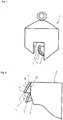
- Fig. 1 illustrates a lifting clamp 1 according to the invention as a schematic diagram, which has a movable jaw 2 and a rigid jaw 2 '. At a contact surface 3 of the movable jaw 2 , a toothing 4 is present.
- the toothing 4 is formed by multi-tooth segments 11 , in the embodiment with two teeth, which are interchangeable as separate components.
- Fig. 2 shows a section of a jaw 2 a lifting clamp 1 , wherein also here at a contact surface 3 of the jaw 2, a toothing 4 is present.
- the toothing 4 is different than in Fig. 1 represented by Einbergsegmente 5 and 5 'formed. These can be exchanged as separate components. They can be turned or turned and are functionally reliable connected by a screw with the jaw 2 .
- the Einbergsegmente 5 and 5 ' are hardened and thus have a higher strength than the jaw 2 itself.
- first edge 6 of one of the Einbergsegmente 5 wear this can be turned once or rotated several times.
- a second edge 7 of a first plane 9 in the direction of the contact surface 3 is aligned functionally, so that the Einbergsegment 5 in concern of a. Load on these again can safely attack.
- the rotation can be done by 90 ° or by 180 °.
- the second edge 7 is aligned functionally by a 180 ° rotation.
- respective individual tooth segments need only be rotated by 90 ° so that a further edge in the direction of the contact surface 3 can be arranged functionally. Namely, it has a square basic shape in the form of the insert.
- edges of a second plane 10 are then used and the process of rotation can be performed as in the first plane 9 , so that effectively eight edges of a respective single tooth segment 5 are available for engagement with a load.
- Each single tooth segment 5 has four edges in the first plane 9 and also four usable edges in the second plane 10 .
Landscapes
- Engineering & Computer Science (AREA)
- Mechanical Engineering (AREA)
- Load-Engaging Elements For Cranes (AREA)
- Gripping Jigs, Holding Jigs, And Positioning Jigs (AREA)
Abstract
Description
- Die Erfindung betrifft eine Hebeklemme zum Handhaben von Lasten, so zum Heben und Wenden von diesen, insbesondere Bleche, Profile und ähnliche Bauteile.
- Hebeklemmen, wie beispielhaft in der
DD 234 658 A5 DD 146 034 DD 155 512 - Während des Einsatzes der Hebeklemmen nutzen sich diese Zähne ab. Eine Arretierung der Last ist nicht mehr im gebotenen Maße gewährleistet. Ein Verschleiß der Zähne während der Handhabe verläuft fließend. Die Grenze zwischen einer ausreichenden Schärfe der Zähne und damit einer Greif Sicherheit und dem Überschreiten eines Verschleißgrades, der keine Greifsicherheit mehr gewährleistet, kann vom Anwender in aller Regel nicht korrekt eingeschätzt werden. Aufgrund des Verschleißes haben Zähne eine größere Oberfläche im Bezug zur Last. Der Anpressdruck verringert sich, die Zähne können sich nicht an der Last arretieren.
- Daher muss die gesamte Klemmbacke ausgetauscht werden. Entweder wird sie demontiert und es werden die Zähne geschärft oder aber die gesamte Klemmbacke muss gewechselt werden. Dies führt zu einem erhöhten Montageaufwand. Sofern ein Wechsel der Klemmbacke notwendig ist, ist mit erhöhtem Materialaufwand und damit erhöhten Kosten zu rechnen. Die Aufgabe der Erfindung besteht darin, eine optimierte Hebeklemme bereitzustellen.
- Die Erfindung wird durch die Merkmale des Hauptanspruchs 1 gelöst. Weitere Ausgestaltungen der Erfindung ergeben sich aus den Unteransprüchen.
- Danach weist eine Hebeklemme zum Handhaben von Lasten mindestens zwei Klemmbacken auf, wobei mindestens eine der Klemmbacken an einer Kontaktfläche, an welche die Last bei einer Handhabe anliegt, eine Zahnung aufweist und die Zahnung wechselbar ist.
- Die Klemmbacken können dabei starr oder beweglich angeordnet sein, wobei in aller Regel eine oder mehrere Klemmbacken beweglich sind. Oftmals ist eine Klemmbacke beweglich und eine weitere Klemmbacke starr an der Hebeklemme angeordnet.
- Dabei kann die Zahnung durch Ein- oder Mehrzahnsegmente gebildet werden, welche separat wechselbar sind. Einzahnsegmente sind separate Zähne. Mehrzahnsegmente sind Segmente mit zwei oder drei Zähnen. Im Wesentlichen ist die Zahnung ein separates Bauteil, das mit der mindestens einen Klemmbacke form- und/oder kraftschlüssig verbunden ist.
- So ist es möglich, bei Verschleiß der Zähne diese einzeln oder aber eine Zahlreihe zumindest partiell auszuwechseln. Da ein Verschleiß in aller Regel nicht bei allen Zähnen gleichmäßig auftritt, sondern vielmehr partiell innerhalb einer Zahnreihe vorhanden ist, können die Bereiche von Zähnen mit höherem Verschleiß leicht gewechselt werden. Gerade auch das erfinderische Mehrzahlsegment besitzt hier Vorteile gegenüber herkömmlichen austauschbaren Backen, bei denen stets das gesamte Bauteil auszutauschen ist. Es reicht dann nämlich aus, mit einem Arbeitsgang nur ein Zahnpaar, also ein Mehrzahnsegment mit zwei Zähnen oder eines mit drei Zähnen zu wechseln und so den beschädigten Bereich auszuwechseln. Dies spart Material und damit auch Kosten.
- Sofern Einzahnsegmente zum Einsatz kommen, also mehrere separat wechselbare Zähne, kann vorgesehen sein, dass die Einzahnsegmente wendbar und/oder drehbar sind. Sie können als Wendeplatten ausgestaltet sein. Bei Verschleiß einer Kante eines Zahns eines Einzahnsegmentes kann dieser mindestens einmal gewendet oder gedreht werden. Bei einer Drehung wird eine zweite Kante einer ersten Ebene in Richtung der Kontaktfläche funktionsgemäß ausgerichtet, sodass der Zahn bei Anliegen einer Last an diese angreifen kann. Bei einem Wenden wird eine dritte Kante einer zweiten Ebene in Richtung der Kontaktfläche funktionsgemäß ausgerichtet. Wenn die Wendeplatte eine quadratische Grundform aufweist, dann weist diese in der ersten Ebene maximal vier Kanten auf und in der zweiten Ebene ebenfalls maximal vier einsetzbare Kanten.
- In weiterer Ausgestaltung kann vorgesehen sein, dass die Zahnung eine höhere Festigkeit aufweist als die mindestens eine Klemmbacke selbst. Sie kann aus einer gehärteten Metalllegierung bestehen. Diese gewährleistet eine höhere Verschleißfestigkeit der Zahnung.
- Auch kann vorgesehen sein, dass die Zahnung eine Verschleißschutzschicht aufweist. Bei Abnutzung einer Schicht wird die Verschleißschutzschicht optisch sichtbar und fungiert als Verschleißanzeige. Die Zahnung ist auszutauschen, das bedeutet, das Einzahnsegment oder das Mehrzahnsegment sind zu wechseln oder, wenn das Einzahnsegment eine Wendeplatte ist, ist diese zu drehen, zu wenden oder aber auch auszutauschen.
- Durch die erfindungsgemäßen Hebeklemmen wird zum einen der Montageaufwand bei einem Wechsel oder bei einer Veränderung der Zahnung reduziert. Dies trifft auch auf den Materialaufwand zu. Materialkosten sinken darüber hinaus, da stets nicht eine gesamte Klemmbacke auszutauschen ist.
- Die Erfindung wird nachfolgend anhand von zwei Ausführungsbeispielen unter Bezugnahme auf die Figuren näher erläutert. Dabei ergeben sich weitere Vorteile, Merkmale und Ausgestaltungen der Erfindung.
- Es zeigen:
-
Fig. 1 eine erfindungsgemäße Hebeklemme als Prinzipskizze, -
Fig. 2 einen Ausschnitt einer Klemmbacke einer Hebeklemme. -
Fig. 1 stellt eine erfindungsgemäße Hebeklemme 1 als Prinzipskizze dar, welche eine bewegliche Klemmbacke 2 und eine starre Klemmbacke 2' aufweist. An einer Kontaktfläche 3 der beweglichen Klemmbacke 2 ist eine Zahnung 4 vorhanden. Die Zahnung 4 wird durch Mehrzahnsegmente 11 gebildet, im Ausführungsbeispiel mit jeweils zwei Zähnen, die als separate Bauteile austauschbar sind. -
Fig. 2 zeigt einen Ausschnitt einer Klemmbacke 2 einer Hebeklemme 1, wobei auch hier an einer Kontaktfläche 3 der Klemmbacke 2 eine Zahnung 4 vorhanden ist. Die Zahnung 4 wird jedoch anders als inFig. 1 dargestellt, durch Einzahnsegmente 5 und 5' gebildet. Diese sind als separate Bauteile wechselbar. Sie können gedreht oder gewendet werden und sind mittels einer Schraubverbindung mit der Klemmbacke 2 funktionssicher verbunden. Die Einzahnsegmente 5 und 5' sind gehärtet und weisen damit eine höhere Festigkeit auf, als die Klemmbacke 2 selbst. - Sie sind im Ausführungsbeispiel 2 als Wendeplatten ausgestaltet. Bei Verschleiß einer ersten Kante 6 eines der Einzahnsegmente 5 kann dieses einmal gewendet oder mehrfach gedreht werden. Bei einer Drehung wird eine zweite Kante 7 einer ersten Ebene 9 in Richtung der Kontaktfläche 3 funktionsgemäß ausgerichtet, sodass das Einzahnsegment 5 bei Anliegen einer. Last an diese wieder sicher angreifen kann. Die Drehung kann um 90° oder um 180° erfolgen. Im Ausführungsbeispiel wird die zweite Kante 7 durch eine 180°-Drehung funktionsgemäß ausgerichtet. Grundsätzlich braucht aber gemäß dem Ausführungsbeispiel dass jeweilige Einzahnsegment nur um 90° gedreht werden, damit eine weitere Kante in Richtung der Kontaktfläche 3 funktionsgemäß angeordnet werden kann. Es weist nämlich in Form der Wendeplatte eine quadratische Grundform auf.
- Bei einem Wenden des Einzahnsegments 5 werden sodann Kanten einer zweiten Ebene 10 genutzt und der Vorgang der Drehung kann wie bei der ersten Ebene 9 erfolgt, ausgeführt werden, sodass effektiv acht Kanten eines jeweiligen Einzahnsegments 5 zu einem Angreifen an eine Last zur Verfügung stehen. Jedes Einzahnsegment 5 weist in der ersten Ebene 9 vier Kanten auf und in der zweiten Ebene 10 ebenfalls vier einsetzbare Kanten.
-
- 1.
- Hebeklemme
- 2.
- Klemmbacke
- 3.
- Kontaktfläche
- 4.
- Zahnung
- 5.
- Einzahnsegment
- 6.
- Erste Kante
- 7.
- Zweite Kante
- 8.
- Dritte Kante
- 9.
- Erste Ebene
- 10.
- Zweite Ebene
- 11.
- Mehrzahnsegment
Claims (7)
- Hebeklemme (1) zum Handhaben von Lasten mit mindestens zwei Klemmbacken (2), wobei mindestens eine der Klemmbacken (2) an einer Kontaktfläche (3), an welche die Last bei einer Handhabe anliegt, eine Zahnung (4) aufweist, wobei die Zahnung (4) wechselbar ist.
- Hebeklemme (1) nach Anspruch 1, wobei die Zahnung (4) durch Ein- oder Mehrzahnsegmente gebildet wird, welche separat wechselbar sind.
- Hebeklemme (1) nach Anspruch 2, wobei die Einzahnsegmente (5) wendbar und/oder drehbar sind.
- Hebeklemme (1) nach einem der vorherigen Ansprüche, wobei die Zahnung (4) ein separates Bauteil ist, das mit der mindestens einen Klemmbacke (2) form- und/oder kraftschlüssig verbunden ist.
- Hebeklemme (1) nach einem der vorherigen Ansprüche, wobei die Zahnung (4) eine höhere Festigkeit aufweist als die mindestens eine Klemmbacke (2).
- Hebeklemme (1) nach einem der vorherigen Ansprüche, wobei die Zahnung (4) aus einer gehärteten Metalllegierung besteht.
- Hebeklemme (1) nach einem der vorherigen Ansprüche, wobei die Zahnung (4) eine Verschleißschutzschicht aufweist.
Applications Claiming Priority (1)
| Application Number | Priority Date | Filing Date | Title |
|---|---|---|---|
| DE102017011810.8A DE102017011810A1 (de) | 2017-12-20 | 2017-12-20 | Hebeklemme |
Publications (2)
| Publication Number | Publication Date |
|---|---|
| EP3502035A1 true EP3502035A1 (de) | 2019-06-26 |
| EP3502035B1 EP3502035B1 (de) | 2023-08-23 |
Family
ID=64744355
Family Applications (1)
| Application Number | Title | Priority Date | Filing Date |
|---|---|---|---|
| EP18000971.4A Active EP3502035B1 (de) | 2017-12-20 | 2018-12-12 | Hebeklemme |
Country Status (3)
| Country | Link |
|---|---|
| EP (1) | EP3502035B1 (de) |
| DE (1) | DE102017011810A1 (de) |
| ES (1) | ES2963212T3 (de) |
Citations (7)
| Publication number | Priority date | Publication date | Assignee | Title |
|---|---|---|---|---|
| US2106373A (en) * | 1938-01-25 | Cable and pipe clutch | ||
| US2548401A (en) * | 1948-11-12 | 1951-04-10 | Joseph W Sherwood | Clamping device |
| DE1481760A1 (de) * | 1967-03-02 | 1969-03-13 | Inst F Foerdertechnik | Greifvorrichtung fuer Platten od.dgl. |
| US4183571A (en) * | 1976-03-04 | 1980-01-15 | J. C. Renfroe And Sons, Inc. | Screw-type lifting clamp |
| DD146034A1 (de) | 1979-09-24 | 1981-01-21 | Heinz Daehnert | Sicherheitseinrichtung an hebeklemmen |
| DD155512A1 (de) | 1980-12-19 | 1982-06-16 | Heinz Daehnert | Feste klemmbacke einer selbstspannenden hebeklemme |
| DD234658A5 (de) | 1984-06-23 | 1986-04-09 | �����@�������@����`@���@�����������@����@���@��k�� | Hebeklemme |
-
2017
- 2017-12-20 DE DE102017011810.8A patent/DE102017011810A1/de not_active Withdrawn
-
2018
- 2018-12-12 EP EP18000971.4A patent/EP3502035B1/de active Active
- 2018-12-12 ES ES18000971T patent/ES2963212T3/es active Active
Patent Citations (7)
| Publication number | Priority date | Publication date | Assignee | Title |
|---|---|---|---|---|
| US2106373A (en) * | 1938-01-25 | Cable and pipe clutch | ||
| US2548401A (en) * | 1948-11-12 | 1951-04-10 | Joseph W Sherwood | Clamping device |
| DE1481760A1 (de) * | 1967-03-02 | 1969-03-13 | Inst F Foerdertechnik | Greifvorrichtung fuer Platten od.dgl. |
| US4183571A (en) * | 1976-03-04 | 1980-01-15 | J. C. Renfroe And Sons, Inc. | Screw-type lifting clamp |
| DD146034A1 (de) | 1979-09-24 | 1981-01-21 | Heinz Daehnert | Sicherheitseinrichtung an hebeklemmen |
| DD155512A1 (de) | 1980-12-19 | 1982-06-16 | Heinz Daehnert | Feste klemmbacke einer selbstspannenden hebeklemme |
| DD234658A5 (de) | 1984-06-23 | 1986-04-09 | �����@�������@����`@���@�����������@����@���@��k�� | Hebeklemme |
Also Published As
| Publication number | Publication date |
|---|---|
| EP3502035B1 (de) | 2023-08-23 |
| DE102017011810A1 (de) | 2019-06-27 |
| ES2963212T3 (es) | 2024-03-25 |
Similar Documents
| Publication | Publication Date | Title |
|---|---|---|
| DE102015106562B4 (de) | Presszange | |
| EP3180138B1 (de) | Biegewerkzeug und greifvorrichtung zum manipulieren des biegewerkzeuges | |
| DE202012103034U1 (de) | Klemmstruktur für ein Wekzeug | |
| DE2356853A1 (de) | Scherenaehnliches instrument und verfahren zu seiner herstellung | |
| EP3108999B1 (de) | Vorrichtung zum bearbeiten eines werkstücks | |
| EP3215317B1 (de) | Spannvorrichtung | |
| DE19854374B4 (de) | Gabelschlüssel | |
| EP3502035B1 (de) | Hebeklemme | |
| EP2998068A1 (de) | Zentrumsspanner mit schnellwechselbacken | |
| DE102013105257A1 (de) | Doppelkeil zum Rahmensetzen | |
| DE202017000023U1 (de) | Schlüsselhalter und Bausatz zum Zusammenbauen eines Schlüsselhalters | |
| DE10329672B4 (de) | Punkturzylinder eines Falzapparates mit wenigstens einer Punkturleiste | |
| DE1811571C3 (de) | Ratschen-Mutternschlüssel | |
| DE102017129928A1 (de) | Laminektomiestanze | |
| DE10238808A1 (de) | Trägerwerkzeug für Schneidplatten mit Feinverstellelementen | |
| DE202007009889U1 (de) | Sensorelement und Klemmhilfsglied zur Halterung des Sensorelementes in einer unterschnittene Wände aufweisenden Nut | |
| DE102015106060A1 (de) | Auflageschiene für eine Spitzenlosschleifmaschine sowie Spitzenlosschleifmaschine mit einer solchen Auflageschiene | |
| DE19835991C2 (de) | Verfahren und Vorrichtung zur Entfernung von angestanzten Innensegmenten aus Etiketten | |
| DE2521378B2 (de) | Zange zum verpressen von kabelverbindern (crimp-werkzeug) | |
| DE515662C (de) | Vorrichtung zum Geradebiegen von Naegeln und aehnlichen Drahtprodukten | |
| DE102024002996A1 (de) | Lastaufnahmevorrichtung | |
| DE102005057828B4 (de) | Schraubenschlüssel | |
| DE202025104573U1 (de) | Vorrichtung zur Aufnahme eines Stahlhalbzeuges | |
| DE9301403U1 (de) | Scherengreifer | |
| AT261493B (de) | Tragvorrichtung für Platten od. dgl. |
Legal Events
| Date | Code | Title | Description |
|---|---|---|---|
| PUAI | Public reference made under article 153(3) epc to a published international application that has entered the european phase |
Free format text: ORIGINAL CODE: 0009012 |
|
| STAA | Information on the status of an ep patent application or granted ep patent |
Free format text: STATUS: THE APPLICATION HAS BEEN PUBLISHED |
|
| AK | Designated contracting states |
Kind code of ref document: A1 Designated state(s): AL AT BE BG CH CY CZ DE DK EE ES FI FR GB GR HR HU IE IS IT LI LT LU LV MC MK MT NL NO PL PT RO RS SE SI SK SM TR |
|
| AX | Request for extension of the european patent |
Extension state: BA ME |
|
| STAA | Information on the status of an ep patent application or granted ep patent |
Free format text: STATUS: REQUEST FOR EXAMINATION WAS MADE |
|
| 17P | Request for examination filed |
Effective date: 20191206 |
|
| RBV | Designated contracting states (corrected) |
Designated state(s): AL AT BE BG CH CY CZ DE DK EE ES FI FR GB GR HR HU IE IS IT LI LT LU LV MC MK MT NL NO PL PT RO RS SE SI SK SM TR |
|
| RAP1 | Party data changed (applicant data changed or rights of an application transferred) |
Owner name: SPANSET AXZION GMBH |
|
| RIC1 | Information provided on ipc code assigned before grant |
Ipc: B66C 1/48 20060101AFI20230216BHEP |
|
| GRAP | Despatch of communication of intention to grant a patent |
Free format text: ORIGINAL CODE: EPIDOSNIGR1 |
|
| STAA | Information on the status of an ep patent application or granted ep patent |
Free format text: STATUS: GRANT OF PATENT IS INTENDED |
|
| INTG | Intention to grant announced |
Effective date: 20230328 |
|
| GRAS | Grant fee paid |
Free format text: ORIGINAL CODE: EPIDOSNIGR3 |
|
| GRAA | (expected) grant |
Free format text: ORIGINAL CODE: 0009210 |
|
| STAA | Information on the status of an ep patent application or granted ep patent |
Free format text: STATUS: THE PATENT HAS BEEN GRANTED |
|
| AK | Designated contracting states |
Kind code of ref document: B1 Designated state(s): AL AT BE BG CH CY CZ DE DK EE ES FI FR GB GR HR HU IE IS IT LI LT LU LV MC MK MT NL NO PL PT RO RS SE SI SK SM TR |
|
| REG | Reference to a national code |
Ref country code: GB Ref legal event code: FG4D Free format text: NOT ENGLISH |
|
| REG | Reference to a national code |
Ref country code: CH Ref legal event code: EP |
|
| REG | Reference to a national code |
Ref country code: DE Ref legal event code: R096 Ref document number: 502018013021 Country of ref document: DE |
|
| REG | Reference to a national code |
Ref country code: IE Ref legal event code: FG4D Free format text: LANGUAGE OF EP DOCUMENT: GERMAN |
|
| REG | Reference to a national code |
Ref country code: LT Ref legal event code: MG9D |
|
| REG | Reference to a national code |
Ref country code: NL Ref legal event code: MP Effective date: 20230823 |
|
| PG25 | Lapsed in a contracting state [announced via postgrant information from national office to epo] |
Ref country code: GR Free format text: LAPSE BECAUSE OF FAILURE TO SUBMIT A TRANSLATION OF THE DESCRIPTION OR TO PAY THE FEE WITHIN THE PRESCRIBED TIME-LIMIT Effective date: 20231124 |
|
| PG25 | Lapsed in a contracting state [announced via postgrant information from national office to epo] |
Ref country code: IS Free format text: LAPSE BECAUSE OF FAILURE TO SUBMIT A TRANSLATION OF THE DESCRIPTION OR TO PAY THE FEE WITHIN THE PRESCRIBED TIME-LIMIT Effective date: 20231223 |
|
| PG25 | Lapsed in a contracting state [announced via postgrant information from national office to epo] |
Ref country code: SE Free format text: LAPSE BECAUSE OF FAILURE TO SUBMIT A TRANSLATION OF THE DESCRIPTION OR TO PAY THE FEE WITHIN THE PRESCRIBED TIME-LIMIT Effective date: 20230823 Ref country code: RS Free format text: LAPSE BECAUSE OF FAILURE TO SUBMIT A TRANSLATION OF THE DESCRIPTION OR TO PAY THE FEE WITHIN THE PRESCRIBED TIME-LIMIT Effective date: 20230823 Ref country code: PT Free format text: LAPSE BECAUSE OF FAILURE TO SUBMIT A TRANSLATION OF THE DESCRIPTION OR TO PAY THE FEE WITHIN THE PRESCRIBED TIME-LIMIT Effective date: 20231226 Ref country code: NO Free format text: LAPSE BECAUSE OF FAILURE TO SUBMIT A TRANSLATION OF THE DESCRIPTION OR TO PAY THE FEE WITHIN THE PRESCRIBED TIME-LIMIT Effective date: 20231123 Ref country code: NL Free format text: LAPSE BECAUSE OF FAILURE TO SUBMIT A TRANSLATION OF THE DESCRIPTION OR TO PAY THE FEE WITHIN THE PRESCRIBED TIME-LIMIT Effective date: 20230823 Ref country code: LV Free format text: LAPSE BECAUSE OF FAILURE TO SUBMIT A TRANSLATION OF THE DESCRIPTION OR TO PAY THE FEE WITHIN THE PRESCRIBED TIME-LIMIT Effective date: 20230823 Ref country code: LT Free format text: LAPSE BECAUSE OF FAILURE TO SUBMIT A TRANSLATION OF THE DESCRIPTION OR TO PAY THE FEE WITHIN THE PRESCRIBED TIME-LIMIT Effective date: 20230823 Ref country code: IS Free format text: LAPSE BECAUSE OF FAILURE TO SUBMIT A TRANSLATION OF THE DESCRIPTION OR TO PAY THE FEE WITHIN THE PRESCRIBED TIME-LIMIT Effective date: 20231223 Ref country code: HR Free format text: LAPSE BECAUSE OF FAILURE TO SUBMIT A TRANSLATION OF THE DESCRIPTION OR TO PAY THE FEE WITHIN THE PRESCRIBED TIME-LIMIT Effective date: 20230823 Ref country code: GR Free format text: LAPSE BECAUSE OF FAILURE TO SUBMIT A TRANSLATION OF THE DESCRIPTION OR TO PAY THE FEE WITHIN THE PRESCRIBED TIME-LIMIT Effective date: 20231124 Ref country code: FI Free format text: LAPSE BECAUSE OF FAILURE TO SUBMIT A TRANSLATION OF THE DESCRIPTION OR TO PAY THE FEE WITHIN THE PRESCRIBED TIME-LIMIT Effective date: 20230823 |
|
| PG25 | Lapsed in a contracting state [announced via postgrant information from national office to epo] |
Ref country code: PL Free format text: LAPSE BECAUSE OF FAILURE TO SUBMIT A TRANSLATION OF THE DESCRIPTION OR TO PAY THE FEE WITHIN THE PRESCRIBED TIME-LIMIT Effective date: 20230823 |
|
| REG | Reference to a national code |
Ref country code: ES Ref legal event code: FG2A Ref document number: 2963212 Country of ref document: ES Kind code of ref document: T3 Effective date: 20240325 |
|
| PG25 | Lapsed in a contracting state [announced via postgrant information from national office to epo] |
Ref country code: SM Free format text: LAPSE BECAUSE OF FAILURE TO SUBMIT A TRANSLATION OF THE DESCRIPTION OR TO PAY THE FEE WITHIN THE PRESCRIBED TIME-LIMIT Effective date: 20230823 Ref country code: RO Free format text: LAPSE BECAUSE OF FAILURE TO SUBMIT A TRANSLATION OF THE DESCRIPTION OR TO PAY THE FEE WITHIN THE PRESCRIBED TIME-LIMIT Effective date: 20230823 Ref country code: EE Free format text: LAPSE BECAUSE OF FAILURE TO SUBMIT A TRANSLATION OF THE DESCRIPTION OR TO PAY THE FEE WITHIN THE PRESCRIBED TIME-LIMIT Effective date: 20230823 Ref country code: DK Free format text: LAPSE BECAUSE OF FAILURE TO SUBMIT A TRANSLATION OF THE DESCRIPTION OR TO PAY THE FEE WITHIN THE PRESCRIBED TIME-LIMIT Effective date: 20230823 Ref country code: CZ Free format text: LAPSE BECAUSE OF FAILURE TO SUBMIT A TRANSLATION OF THE DESCRIPTION OR TO PAY THE FEE WITHIN THE PRESCRIBED TIME-LIMIT Effective date: 20230823 Ref country code: SK Free format text: LAPSE BECAUSE OF FAILURE TO SUBMIT A TRANSLATION OF THE DESCRIPTION OR TO PAY THE FEE WITHIN THE PRESCRIBED TIME-LIMIT Effective date: 20230823 |
|
| REG | Reference to a national code |
Ref country code: DE Ref legal event code: R097 Ref document number: 502018013021 Country of ref document: DE |
|
| PLBE | No opposition filed within time limit |
Free format text: ORIGINAL CODE: 0009261 |
|
| STAA | Information on the status of an ep patent application or granted ep patent |
Free format text: STATUS: NO OPPOSITION FILED WITHIN TIME LIMIT |
|
| 26N | No opposition filed |
Effective date: 20240524 |
|
| PG25 | Lapsed in a contracting state [announced via postgrant information from national office to epo] |
Ref country code: SI Free format text: LAPSE BECAUSE OF FAILURE TO SUBMIT A TRANSLATION OF THE DESCRIPTION OR TO PAY THE FEE WITHIN THE PRESCRIBED TIME-LIMIT Effective date: 20230823 |
|
| REG | Reference to a national code |
Ref country code: CH Ref legal event code: PL |
|
| PG25 | Lapsed in a contracting state [announced via postgrant information from national office to epo] |
Ref country code: LU Free format text: LAPSE BECAUSE OF NON-PAYMENT OF DUE FEES Effective date: 20231212 |
|
| PG25 | Lapsed in a contracting state [announced via postgrant information from national office to epo] |
Ref country code: MC Free format text: LAPSE BECAUSE OF FAILURE TO SUBMIT A TRANSLATION OF THE DESCRIPTION OR TO PAY THE FEE WITHIN THE PRESCRIBED TIME-LIMIT Effective date: 20230823 |
|
| REG | Reference to a national code |
Ref country code: BE Ref legal event code: MM Effective date: 20231231 |
|
| PG25 | Lapsed in a contracting state [announced via postgrant information from national office to epo] |
Ref country code: MC Free format text: LAPSE BECAUSE OF FAILURE TO SUBMIT A TRANSLATION OF THE DESCRIPTION OR TO PAY THE FEE WITHIN THE PRESCRIBED TIME-LIMIT Effective date: 20230823 Ref country code: LU Free format text: LAPSE BECAUSE OF NON-PAYMENT OF DUE FEES Effective date: 20231212 |
|
| REG | Reference to a national code |
Ref country code: IE Ref legal event code: MM4A |
|
| PG25 | Lapsed in a contracting state [announced via postgrant information from national office to epo] |
Ref country code: IE Free format text: LAPSE BECAUSE OF NON-PAYMENT OF DUE FEES Effective date: 20231212 |
|
| PG25 | Lapsed in a contracting state [announced via postgrant information from national office to epo] |
Ref country code: BE Free format text: LAPSE BECAUSE OF NON-PAYMENT OF DUE FEES Effective date: 20231231 |
|
| PG25 | Lapsed in a contracting state [announced via postgrant information from national office to epo] |
Ref country code: CH Free format text: LAPSE BECAUSE OF NON-PAYMENT OF DUE FEES Effective date: 20231231 |
|
| PG25 | Lapsed in a contracting state [announced via postgrant information from national office to epo] |
Ref country code: IE Free format text: LAPSE BECAUSE OF NON-PAYMENT OF DUE FEES Effective date: 20231212 Ref country code: CH Free format text: LAPSE BECAUSE OF NON-PAYMENT OF DUE FEES Effective date: 20231231 Ref country code: BE Free format text: LAPSE BECAUSE OF NON-PAYMENT OF DUE FEES Effective date: 20231231 |
|
| PG25 | Lapsed in a contracting state [announced via postgrant information from national office to epo] |
Ref country code: BG Free format text: LAPSE BECAUSE OF FAILURE TO SUBMIT A TRANSLATION OF THE DESCRIPTION OR TO PAY THE FEE WITHIN THE PRESCRIBED TIME-LIMIT Effective date: 20230823 |
|
| PG25 | Lapsed in a contracting state [announced via postgrant information from national office to epo] |
Ref country code: BG Free format text: LAPSE BECAUSE OF FAILURE TO SUBMIT A TRANSLATION OF THE DESCRIPTION OR TO PAY THE FEE WITHIN THE PRESCRIBED TIME-LIMIT Effective date: 20230823 |
|
| REG | Reference to a national code |
Ref country code: AT Ref legal event code: MM01 Ref document number: 1602407 Country of ref document: AT Kind code of ref document: T Effective date: 20231212 |
|
| PG25 | Lapsed in a contracting state [announced via postgrant information from national office to epo] |
Ref country code: AT Free format text: LAPSE BECAUSE OF NON-PAYMENT OF DUE FEES Effective date: 20231212 |
|
| PG25 | Lapsed in a contracting state [announced via postgrant information from national office to epo] |
Ref country code: CY Free format text: LAPSE BECAUSE OF FAILURE TO SUBMIT A TRANSLATION OF THE DESCRIPTION OR TO PAY THE FEE WITHIN THE PRESCRIBED TIME-LIMIT; INVALID AB INITIO Effective date: 20181212 |
|
| PG25 | Lapsed in a contracting state [announced via postgrant information from national office to epo] |
Ref country code: HU Free format text: LAPSE BECAUSE OF FAILURE TO SUBMIT A TRANSLATION OF THE DESCRIPTION OR TO PAY THE FEE WITHIN THE PRESCRIBED TIME-LIMIT; INVALID AB INITIO Effective date: 20181212 |
|
| PG25 | Lapsed in a contracting state [announced via postgrant information from national office to epo] |
Ref country code: TR Free format text: LAPSE BECAUSE OF FAILURE TO SUBMIT A TRANSLATION OF THE DESCRIPTION OR TO PAY THE FEE WITHIN THE PRESCRIBED TIME-LIMIT Effective date: 20230823 |
|
| PGFP | Annual fee paid to national office [announced via postgrant information from national office to epo] |
Ref country code: DE Payment date: 20251010 Year of fee payment: 8 |
|
| PGFP | Annual fee paid to national office [announced via postgrant information from national office to epo] |
Ref country code: GB Payment date: 20251218 Year of fee payment: 8 |
|
| PGFP | Annual fee paid to national office [announced via postgrant information from national office to epo] |
Ref country code: FR Payment date: 20251217 Year of fee payment: 8 |
|
| PGFP | Annual fee paid to national office [announced via postgrant information from national office to epo] |
Ref country code: ES Payment date: 20260119 Year of fee payment: 8 |
|
| PGFP | Annual fee paid to national office [announced via postgrant information from national office to epo] |
Ref country code: IT Payment date: 20251231 Year of fee payment: 8 |