EP3501911B1 - Vorrichtung und verfahren zur steuerung eines aktiven fahrzeugsitzgurtes - Google Patents
Vorrichtung und verfahren zur steuerung eines aktiven fahrzeugsitzgurtes Download PDFInfo
- Publication number
- EP3501911B1 EP3501911B1 EP18188219.2A EP18188219A EP3501911B1 EP 3501911 B1 EP3501911 B1 EP 3501911B1 EP 18188219 A EP18188219 A EP 18188219A EP 3501911 B1 EP3501911 B1 EP 3501911B1
- Authority
- EP
- European Patent Office
- Prior art keywords
- rollover
- seatbelt
- vehicle
- airbag
- control signal
- Prior art date
- Legal status (The legal status is an assumption and is not a legal conclusion. Google has not performed a legal analysis and makes no representation as to the accuracy of the status listed.)
- Active
Links
Images


Classifications
-
- B—PERFORMING OPERATIONS; TRANSPORTING
- B60—VEHICLES IN GENERAL
- B60R—VEHICLES, VEHICLE FITTINGS, OR VEHICLE PARTS, NOT OTHERWISE PROVIDED FOR
- B60R21/00—Arrangements or fittings on vehicles for protecting or preventing injuries to occupants or pedestrians in case of accidents or other traffic risks
- B60R21/01—Electrical circuits for triggering passive safety arrangements, e.g. airbags, safety belt tighteners, in case of vehicle accidents or impending vehicle accidents
- B60R21/013—Electrical circuits for triggering passive safety arrangements, e.g. airbags, safety belt tighteners, in case of vehicle accidents or impending vehicle accidents including means for detecting collisions, impending collisions or roll-over
-
- B—PERFORMING OPERATIONS; TRANSPORTING
- B60—VEHICLES IN GENERAL
- B60R—VEHICLES, VEHICLE FITTINGS, OR VEHICLE PARTS, NOT OTHERWISE PROVIDED FOR
- B60R21/00—Arrangements or fittings on vehicles for protecting or preventing injuries to occupants or pedestrians in case of accidents or other traffic risks
- B60R21/02—Occupant safety arrangements or fittings, e.g. crash pads
- B60R21/16—Inflatable occupant restraints or confinements designed to inflate upon impact or impending impact, e.g. air bags
-
- B—PERFORMING OPERATIONS; TRANSPORTING
- B60—VEHICLES IN GENERAL
- B60R—VEHICLES, VEHICLE FITTINGS, OR VEHICLE PARTS, NOT OTHERWISE PROVIDED FOR
- B60R22/00—Safety belts or body harnesses in vehicles
- B60R22/34—Belt retractors, e.g. reels
-
- B—PERFORMING OPERATIONS; TRANSPORTING
- B60—VEHICLES IN GENERAL
- B60R—VEHICLES, VEHICLE FITTINGS, OR VEHICLE PARTS, NOT OTHERWISE PROVIDED FOR
- B60R22/00—Safety belts or body harnesses in vehicles
- B60R22/48—Control systems, alarms, or interlock systems, for the correct application of the belt or harness
-
- B—PERFORMING OPERATIONS; TRANSPORTING
- B60—VEHICLES IN GENERAL
- B60W—CONJOINT CONTROL OF VEHICLE SUB-UNITS OF DIFFERENT TYPE OR DIFFERENT FUNCTION; CONTROL SYSTEMS SPECIALLY ADAPTED FOR HYBRID VEHICLES; ROAD VEHICLE DRIVE CONTROL SYSTEMS FOR PURPOSES NOT RELATED TO THE CONTROL OF A PARTICULAR SUB-UNIT
- B60W40/00—Estimation or calculation of non-directly measurable driving parameters for road vehicle drive control systems not related to the control of a particular sub unit, e.g. by using mathematical models
- B60W40/10—Estimation or calculation of non-directly measurable driving parameters for road vehicle drive control systems not related to the control of a particular sub unit, e.g. by using mathematical models related to vehicle motion
- B60W40/105—Speed
-
- B—PERFORMING OPERATIONS; TRANSPORTING
- B60—VEHICLES IN GENERAL
- B60W—CONJOINT CONTROL OF VEHICLE SUB-UNITS OF DIFFERENT TYPE OR DIFFERENT FUNCTION; CONTROL SYSTEMS SPECIALLY ADAPTED FOR HYBRID VEHICLES; ROAD VEHICLE DRIVE CONTROL SYSTEMS FOR PURPOSES NOT RELATED TO THE CONTROL OF A PARTICULAR SUB-UNIT
- B60W40/00—Estimation or calculation of non-directly measurable driving parameters for road vehicle drive control systems not related to the control of a particular sub unit, e.g. by using mathematical models
- B60W40/10—Estimation or calculation of non-directly measurable driving parameters for road vehicle drive control systems not related to the control of a particular sub unit, e.g. by using mathematical models related to vehicle motion
- B60W40/109—Lateral acceleration
-
- B—PERFORMING OPERATIONS; TRANSPORTING
- B60—VEHICLES IN GENERAL
- B60W—CONJOINT CONTROL OF VEHICLE SUB-UNITS OF DIFFERENT TYPE OR DIFFERENT FUNCTION; CONTROL SYSTEMS SPECIALLY ADAPTED FOR HYBRID VEHICLES; ROAD VEHICLE DRIVE CONTROL SYSTEMS FOR PURPOSES NOT RELATED TO THE CONTROL OF A PARTICULAR SUB-UNIT
- B60W40/00—Estimation or calculation of non-directly measurable driving parameters for road vehicle drive control systems not related to the control of a particular sub unit, e.g. by using mathematical models
- B60W40/10—Estimation or calculation of non-directly measurable driving parameters for road vehicle drive control systems not related to the control of a particular sub unit, e.g. by using mathematical models related to vehicle motion
- B60W40/114—Yaw movement
-
- B—PERFORMING OPERATIONS; TRANSPORTING
- B60—VEHICLES IN GENERAL
- B60W—CONJOINT CONTROL OF VEHICLE SUB-UNITS OF DIFFERENT TYPE OR DIFFERENT FUNCTION; CONTROL SYSTEMS SPECIALLY ADAPTED FOR HYBRID VEHICLES; ROAD VEHICLE DRIVE CONTROL SYSTEMS FOR PURPOSES NOT RELATED TO THE CONTROL OF A PARTICULAR SUB-UNIT
- B60W50/00—Details of control systems for road vehicle drive control not related to the control of a particular sub-unit, e.g. process diagnostic or vehicle driver interfaces
- B60W50/0098—Details of control systems ensuring comfort, safety or stability not otherwise provided for
-
- B—PERFORMING OPERATIONS; TRANSPORTING
- B62—LAND VEHICLES FOR TRAVELLING OTHERWISE THAN ON RAILS
- B62D—MOTOR VEHICLES; TRAILERS
- B62D15/00—Steering not otherwise provided for
- B62D15/02—Steering position indicators ; Steering position determination; Steering aids
- B62D15/021—Determination of steering angle
-
- B—PERFORMING OPERATIONS; TRANSPORTING
- B60—VEHICLES IN GENERAL
- B60R—VEHICLES, VEHICLE FITTINGS, OR VEHICLE PARTS, NOT OTHERWISE PROVIDED FOR
- B60R21/00—Arrangements or fittings on vehicles for protecting or preventing injuries to occupants or pedestrians in case of accidents or other traffic risks
- B60R2021/0002—Type of accident
- B60R2021/0018—Roll-over
-
- B—PERFORMING OPERATIONS; TRANSPORTING
- B60—VEHICLES IN GENERAL
- B60R—VEHICLES, VEHICLE FITTINGS, OR VEHICLE PARTS, NOT OTHERWISE PROVIDED FOR
- B60R21/00—Arrangements or fittings on vehicles for protecting or preventing injuries to occupants or pedestrians in case of accidents or other traffic risks
- B60R21/01—Electrical circuits for triggering passive safety arrangements, e.g. airbags, safety belt tighteners, in case of vehicle accidents or impending vehicle accidents
- B60R2021/01034—Controlling a plurality of restraint devices
-
- B—PERFORMING OPERATIONS; TRANSPORTING
- B60—VEHICLES IN GENERAL
- B60R—VEHICLES, VEHICLE FITTINGS, OR VEHICLE PARTS, NOT OTHERWISE PROVIDED FOR
- B60R21/00—Arrangements or fittings on vehicles for protecting or preventing injuries to occupants or pedestrians in case of accidents or other traffic risks
- B60R21/01—Electrical circuits for triggering passive safety arrangements, e.g. airbags, safety belt tighteners, in case of vehicle accidents or impending vehicle accidents
- B60R2021/01204—Actuation parameters of safety arrangents
- B60R2021/01252—Devices other than bags
- B60R2021/01265—Seat belts
-
- B—PERFORMING OPERATIONS; TRANSPORTING
- B60—VEHICLES IN GENERAL
- B60R—VEHICLES, VEHICLE FITTINGS, OR VEHICLE PARTS, NOT OTHERWISE PROVIDED FOR
- B60R21/00—Arrangements or fittings on vehicles for protecting or preventing injuries to occupants or pedestrians in case of accidents or other traffic risks
- B60R21/01—Electrical circuits for triggering passive safety arrangements, e.g. airbags, safety belt tighteners, in case of vehicle accidents or impending vehicle accidents
- B60R2021/01286—Electronic control units
-
- B—PERFORMING OPERATIONS; TRANSPORTING
- B60—VEHICLES IN GENERAL
- B60R—VEHICLES, VEHICLE FITTINGS, OR VEHICLE PARTS, NOT OTHERWISE PROVIDED FOR
- B60R22/00—Safety belts or body harnesses in vehicles
- B60R22/48—Control systems, alarms, or interlock systems, for the correct application of the belt or harness
- B60R2022/4808—Sensing means arrangements therefor
- B60R2022/4816—Sensing means arrangements therefor for sensing locking of buckle
-
- B—PERFORMING OPERATIONS; TRANSPORTING
- B60—VEHICLES IN GENERAL
- B60W—CONJOINT CONTROL OF VEHICLE SUB-UNITS OF DIFFERENT TYPE OR DIFFERENT FUNCTION; CONTROL SYSTEMS SPECIALLY ADAPTED FOR HYBRID VEHICLES; ROAD VEHICLE DRIVE CONTROL SYSTEMS FOR PURPOSES NOT RELATED TO THE CONTROL OF A PARTICULAR SUB-UNIT
- B60W2520/00—Input parameters relating to overall vehicle dynamics
- B60W2520/10—Longitudinal speed
-
- B—PERFORMING OPERATIONS; TRANSPORTING
- B60—VEHICLES IN GENERAL
- B60W—CONJOINT CONTROL OF VEHICLE SUB-UNITS OF DIFFERENT TYPE OR DIFFERENT FUNCTION; CONTROL SYSTEMS SPECIALLY ADAPTED FOR HYBRID VEHICLES; ROAD VEHICLE DRIVE CONTROL SYSTEMS FOR PURPOSES NOT RELATED TO THE CONTROL OF A PARTICULAR SUB-UNIT
- B60W2520/00—Input parameters relating to overall vehicle dynamics
- B60W2520/12—Lateral speed
- B60W2520/125—Lateral acceleration
-
- B—PERFORMING OPERATIONS; TRANSPORTING
- B60—VEHICLES IN GENERAL
- B60W—CONJOINT CONTROL OF VEHICLE SUB-UNITS OF DIFFERENT TYPE OR DIFFERENT FUNCTION; CONTROL SYSTEMS SPECIALLY ADAPTED FOR HYBRID VEHICLES; ROAD VEHICLE DRIVE CONTROL SYSTEMS FOR PURPOSES NOT RELATED TO THE CONTROL OF A PARTICULAR SUB-UNIT
- B60W2520/00—Input parameters relating to overall vehicle dynamics
- B60W2520/14—Yaw
-
- B—PERFORMING OPERATIONS; TRANSPORTING
- B60—VEHICLES IN GENERAL
- B60W—CONJOINT CONTROL OF VEHICLE SUB-UNITS OF DIFFERENT TYPE OR DIFFERENT FUNCTION; CONTROL SYSTEMS SPECIALLY ADAPTED FOR HYBRID VEHICLES; ROAD VEHICLE DRIVE CONTROL SYSTEMS FOR PURPOSES NOT RELATED TO THE CONTROL OF A PARTICULAR SUB-UNIT
- B60W2520/00—Input parameters relating to overall vehicle dynamics
- B60W2520/18—Roll
-
- B—PERFORMING OPERATIONS; TRANSPORTING
- B60—VEHICLES IN GENERAL
- B60W—CONJOINT CONTROL OF VEHICLE SUB-UNITS OF DIFFERENT TYPE OR DIFFERENT FUNCTION; CONTROL SYSTEMS SPECIALLY ADAPTED FOR HYBRID VEHICLES; ROAD VEHICLE DRIVE CONTROL SYSTEMS FOR PURPOSES NOT RELATED TO THE CONTROL OF A PARTICULAR SUB-UNIT
- B60W2520/00—Input parameters relating to overall vehicle dynamics
- B60W2520/28—Wheel speed
Definitions
- the present disclosure relates to an apparatus and method for controlling a vehicular active seatbelt, and more particularly, to an apparatus and method for actively controlling an active seatbelt positioned in a vehicle seat in response to state information that is collected or detected during vehicle driving.
- a seatbelt is an example of a safety device for elastically restraining a passenger body to prevent serious injury when sudden shock due to collision or crash during driving is applied.
- a vehicular seatbelt is operatively connected to a seatbelt indicator that notifies a driver about a wearing state because of importance of wearing the seatbelt.
- the seatbelt indicator is configured in such a way that a vehicular electronic control unit (ECU) receives a signal of a contact sensor installed in the form of a buckle of a seatbelt and lights a belt display included in a cluster using the signal or continuously sounds an alarm using a buzzer instead of the belt display and, thus, notifies the driver about a wearing state of the seatbelt.
- ECU vehicular electronic control unit
- an active seatbelt is configured in such a way that a driving motor installed in the seatbelt pre-pulls or instantly pulls the seatbelt to definitely fix a passenger to a seat when forward collision is predicted or an emergency such as a sharp turn occurs and, thus, is proposed as a smart safety system for minimizing passenger injury due to shock.
- a conventional active seatbelt control apparatus has a limit in that an active seatbelt is not normally operated when danger of a rollover accident occurs, e.g., when emergency braking is not performed by a forward collision avoidance assist system (FCA) or a vehicle descends along the embankment or climbs up a hill.
- FCA forward collision avoidance assist system
- the conventional active seatbelt control apparatus has difficulty in actively controlling a seatbelt.
- US 2009/099735 A1 discloses an automobile rollover prediction and restraint device deployment system, comprising a plurality of automobile data sensors to generate a plurality of data signals, and a controller to receive the data signals and configured to deploy resettable and non-resettable restraint devices, wherein the controller is configured to activate at least one resettable restraint device when one or more of the data signals exceed a first threshold, indicating that the vehicle is in a position or undergoing movement that indicates a potential for vehicle rollover, and to de-activate the at least one resettable restraint device when one or more of the data signals fall below the first threshold.
- An objective of the present disclosure is to provide an apparatus and method for recognizing a rollover accident and an emergency situation during driving on a rough road and transmitting a signal for control of a pre-safe seat belt (PSB) by an airbag control unit (ACU), thereby enhancing performance for protecting a passenger via advance restraint control.
- PSB pre-safe seat belt
- ACU airbag control unit
- Another objective of the present disclosure is to provide an apparatus and method for determining a situation in which a vehicle is in danger of a rollover accident and controlling a pre-safe seat belt (PSB) to restrain (fasten) an electric seatbelt in advance before an airbag is deployed.
- PSB pre-safe seat belt
- Another objective of the present disclosure is to provide an apparatus and method for controlling a pre-safe seat belt (PSB) using an airbag control unit (ACU) for collecting driving state information of a vehicle for safety of a passenger to simplify specifications of a controller for control of the PSB, thereby enhancing productivity.
- PSB pre-safe seat belt
- ACU airbag control unit
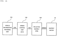
- FIG. 1A is a diagram for explanation of a first example of an apparatus for controlling an active seatbelt.
- FIG. 1B is a diagram for explanation of a second example of an apparatus for controlling an active seatbelt.
- the apparatuses for controlling an active seatbelt may have different structures depending on a connection form between an airbag control apparatus and an active seatbelt apparatus through a vehicular network.
- the apparatus for controlling an active seatbelt may include a vehicle information providing unit 12A, an airbag control unit (ACU) 14A, a pre-active seatbelt (PSB) 16A, and a seatbelt motor 18.
- the vehicle information providing unit 12A may collect and transmit driving information used to determine a situation for restraint control of the PSB 16A, such as vehicle speed, a vehicle behavior, a buckle state, and a collision warning system.
- the ACU 14A may determine and control an operating state of the PSB 16A.
- the PSB 16A may include a driving driver for directly driving the seatbelt motor 18.
- an ACU 14B may be connected to a vehicle information providing unit 12B and a PSB 16B via CAN communication that is a vehicular network.
- FIG. 1A illustrates the case in which the vehicle information providing unit 12A is connected to the PSB 16A through the ACU 14A and, on the other hand, FIG. 1B illustrates the case in which the vehicle information providing unit 12A is connected directly to the PSB 16A.
- the PSB 16B and the seatbelt motor 18 may be connected to each other through a wire but not network communication.
- the apparatus for controlling an active seatbelt may include the seatbelt motor 18 for controlling restraint and release of a seatbelt, the PSBs 16A and 16B including a seatbelt driving controller 58 for outputting a motor control signal for control of the seatbelt motor, and the ACUs 14A and 14B for providing the determination result for determining the motor control signal.
- the seatbelt driving controller 58 may be an electric circuitry that executes instructions of software which thereby performs various functions described hereinafter.
- the ACUs 14A and 14B may determine a safety state based on driving information collected during vehicle driving and, then, determine the determination result in response to whether an airbag is deployed.
- FIG. 2 is a diagram for explanation of a third example of an apparatus for controlling an active seatbelt.
- the apparatus for controlling an active seatbelt may include a vehicle information providing unit 20 including a plurality of sensors or detectors for colleting driving information of a vehicle.
- the plurality of sensors or detectors included in the vehicle information providing unit 20 may be changed in some embodiments.
- the plurality of sensors or detectors may include a forward collision warning system (FCW) 24, a side collision warning system (SCW) 26, a rear collision warning system (RCW) 28, and so on.
- the forward collision warning system (FCW) for warning a driver about danger when danger of forward collision with a leading vehicle may also be provided through smart cruise control (SCC) for driving a vehicle while mainlining a predetermined distance from a leading vehicle.
- SCC smart cruise control
- the side collision warning system (SCW) for warning a driver about danger when danger of side collision with a neighboring vehicle positioned at a lateral side may also be provided through a lane keeping assist system (LKAS) for control of vehicle steering as well as for warning a driver about danger using vibration, sound, or the like upon determining that the vehicle departs from a road or a lane.
- LKAS lane keeping assist system
- the rear collision warning system (RCW) for warning a driver about danger when rear collision with a neighboring vehicle positioned at a rear side may also be provided through a blind spot warning system (BSW) that detects a vehicle or an object when the vehicle or the object approaches a left/right blind spot during vehicle driving and notifies the driver of the information.
- BSW blind spot warning system
- Information on the possibility of vehicle collision or crash may be pre-collected through a plurality of warning devices installed in a vehicle and the information may be provided to an airbag control unit (ACU) 50 that is connected to the warning devices using a CAN communication method as a vehicular network.
- ACU airbag control unit
- the vehicle information providing unit 20 may include a central gateway (CGW) 22 that is connected to a head unit for transmitting information on whether a seatbelt is fastened.
- the vehicle information providing unit 20 may further include a steering angle sensor (SAS) 32 for detecting the manipulation speed and angle of a steering wheel to perform steering control, vehicle dynamic control (VDC), ABS control, and so on, and an electronic stability control device (ESC) 34 for analyzing a state of the steering wheel to adjust a traveling direction of a vehicle when a target direction of the vehicle is different from an actual direction.
- SAS steering angle sensor
- VDC vehicle dynamic control
- ESC electronic stability control device
- the ACU 50 may include a processor 51 having a non-transitory memory storing software instructions which, when executed by the processor 51, provide the functionalities of: a condition determination module 52 for determining a rollover state of a vehicle, an airbag controller 54 for detecting vehicle crash to deploy an airbag, and a seatbelt control determination module 56 for determining a safety state based on driving information and for determining a determination result in response to the information on the rollover state and whether the airbag is deployed, which are transmitted from the condition determination module 52 and the airbag controller 54.
- the airbag controller 54 of the processor 51 may collect information on crash from a front/side impact sensor (FIS/SIS) 40 that detects acceleration or pressure and transmits the detected information to the ACU in an initial crash stage.
- FIS/SIS front/side impact sensor
- the seatbelt control determination module 56 of the processor 51 may permit a motor control signal for restraint control of a seatbelt to be output from a seatbelt driving controller 58 in response to a safety state in which an airbag is not deployed and may not permit the seatbelt driving controller 58 to perform restraint control in a state in which an airbag is deployed.
- the ACU 50 may further include a collision sensor 42 for detecting vehicle collision, a rollover detection sensor 46 for detecting vehicle rollover, and an inertial measurement unit (IMU) 44 for measuring acceleration and rotary motion of a vehicle.
- a collision sensor 42 for detecting vehicle collision
- a rollover detection sensor 46 for detecting vehicle rollover
- an inertial measurement unit (IMU) 44 for measuring acceleration and rotary motion of a vehicle.
- Driving information transmitted from the vehicle information providing unit 20 may include wheel speed, a steering angle, lateral acceleration, a yaw rate, rollover angular velocity, and a rollover angle.
- the ACU 50 may determine a first condition about whether vehicle speed in a traveling direction is greater than predetermined threshold speed, a second condition about whether vehicle lateral speed is greater than a predetermined first lateral speed threshold value, and a third condition for determination of a vehicle rollover situation and determine a safety state in response to a determination result.
- the rollover situation may be determined in response to rollover angular velocity and a rollover angle and the third condition may be greater than a threshold value that is lower than a condition in which an airbag disposed at a lateral side in the vehicle is deployed.
- the driving information may be transmitted from a yaw rate sensor, an inertial measurement sensor, and a rollover detection sensor.
- the driving information may include a value transmitted from a vehicle speed and rollover detection sensor.
- the rollover detection sensor may output Y-direction acceleration (Low Y), Z-direction acceleration (Low Z), and rollover angular velocity (Roll rate).
- the ACU 50 may calculate the rollover angle from the rollover angular velocity.
- the condition determination module 52 may receive the rollover angular velocity and calculate the rollover angle and, then, transmit the rollover angle to the seatbelt control determination module 56.
- the ACU 50 may determine whether all of the Y-direction acceleration (Low Y), the Z-direction acceleration (Low Z), the rollover angular velocity (Roll rate), and a rollover angle are greater than respective predetermined threshold values.
- the seatbelt control determination module 56 may determine whether driving information from the vehicle information providing unit 20 or the condition determination module 52 is greater than a corresponding threshold value to determine a current state of a vehicle. Upon determining that a driver and a passenger in a vehicle are in danger, a seatbelt may be further restrained to enhance safety of the driver or the passenger.
- the ACU 50 may feed an operation state of a seatbelt motor, corresponding to the motor control signal, back to the airbag controller 54 and display information on a vehicle instrument panel (e.g., a display) in response to the motor control signal.
- the driving information may include advance information on crash danger and the determination result of the seatbelt control determination module 56 may be output before a vehicle detects crash.
- the motor control signal output from the seatbelt driving controller 58 may have a pulse width or current level for restraining a seatbelt and a seatbelt driving motor 38 may restrain a seatbelt in response to the pulse width or the current level.
- the ACU 50 may receive information from an external forward collision sensor, a side collision sensor, and the like in the case of current forward/side collision and perform a crash algorithm for deploying an airbag using an internal crash sensor.
- the ACU 50 may determine whether a seatbelt is restrained based on the driving information received from the inertial measurement unit (IMU) 44 including a yaw rate sensor and an Ax and Ay acceleration sensor, for checking a behavior degree such as vehicle rotation, and the rollover detection sensor 46 including a roll rate sensor and an Ax and Ay acceleration sensor, for detecting a rollover accident of a vehicle.
- IMU inertial measurement unit
- the ACU 50 may include the condition determination module 52 and the seatbelt control determination module 56, for determining a condition about a restraint function of a seatbelt using the driving information of the vehicle and the information transmitted from the IMU 44 and the collision sensor 42.
- the seatbelt driving controller 58 may output the motor control signal according to the information determined by the seatbelt control determination module 56 that receives information on airbag deployment from the airbag controller 54 and determines seatbelt restraining.
- the seatbelt control determination module 56 may perform an algorithm for determining control of a plurality of seatbelts or include a plurality of determination logics or circuits.
- the condition determination module 52 may estimate a dynamic condition for estimating a condition such as vehicle rollover and a traverse behavior using information output from the IMU 44, information output from the rollover detection sensor 46, a steering angle, vehicle speed, and brake pressure information.
- the seatbelt control determination module 56 may include a first condition determination module for determining control of a dynamic condition of a restraint operation of a seatbelt using information output from the condition determination module 52 and information on whether a seatbelt is fastened, and a second condition determination module for determining whether a seatbelt is restrained using free crash determination information of a vehicle, information on whether a seatbelt is fastened, and basic crash algorithm information of the airbag controller 54.
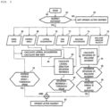
- FIG. 3 is a diagram for explanation of a first example of a method of controlling an active seatbelt.
- the method of controlling the active seatbelt may be started (60) by checking whether a seatbelt is fastened (62). Control of an active seatbelt may be performed for every seatbelt in a vehicle. When the seatbelt is not fastened, control of the active seatbelt may not be performed (64). Then, whether average vehicle speed is equal to or greater than threshold speed may be checked based on information on wheel speed 66 (78). When the vehicle speed is lower than the threshold speed, control of the active seatbelt may not be performed.
- lateral acceleration or a yaw rate may be calculated using information on a steering angle 68 and the wheel speed 66 (80).
- lateral acceleration 70 and yaw rate 72 may be received to perform calculation corresponding to a lateral-direction situation (80). Then, the value calculated in response to the lateral-direction situation and a threshold value may be compared (86).
- Rollover acceleration 74 and rollover angular velocity 76 may be received and, then, calculation corresponding to a situation of a rollover accident may be performed (84). Then, the rollover situation may be determined based on the calculated value (88) and whether an airbag is deployed may be checked (90).
- the active seatbelt may be operated (92).
- whether a seatbelt is fastened may be determined, a restraint operation of an active seatbelt may not be performed when the seatbelt is not fastened, and a time point when the restraint operation of the active seatbelt is to be performed may be determined through an airbag controller when the seatbelt is fastened.
- the situation for the restraint operation of the active seatbelt may be determined using the wheel speed 66, the steering angle 68, the lateral acceleration 70, the yaw rate 72, collision acceleration (not shown), the rollover acceleration 74, and the rollover angular velocity 76.
- a lateral-direction situation reference value which is calculated using factor values used to calculate lateral acceleration and a yaw rate using the wheel speed 66 and the steering angle 68 and information of the lateral acceleration 70 and the yaw rate 72, is greater than a situation reference threshold value (86)
- the restraint operation of the active seatbelt may be performed.
- the restraint operation of the active seatbelt may be performed only when average vehicle speed is greater than predetermined threshold speed based on the wheel speed 66 (78).
- FIG. 4 is a diagram for explanation of a time point of restraint control of an active seatbelt.
- FIG. 4 shows determination of a time point at which a restraint operation of an active seatbelt is performed in response to collected information during vehicle driving.
- (a) to (c) of FIG. 4 respectively show examples of setting threshold values of Y-direction acceleration (Low Y), Z-direction acceleration (Low Z), rollover angular velocity (Roll rate), and rollover angle (Roll Angle) when a rollover accident occurs.
- threshold values of the rollover angular velocity and the rollover angle for performing the restraint operation of the active seatbelt a range of a threshold value for performing a restraint operation of a separate active seatbelt may be set and the restraint operation of the active seatbelt may be performed in advance prior to determination of whether a side airbag is deployed for rollover.
- the dynamic rollover algorithm of the airbag control unit may determine a rollover situation when a value of Y-direction acceleration (Low Y), Z-direction acceleration (Low Z), rollover angular velocity (Roll rate), and rollover angle (Roll Angle) of a rollover sensor is greater than a threshold value tuned according to the characteristics of a vehicle (112, 114, 116, and 118). To this end, the rollover angle may be calculated from the rollover angular velocity (110). Whether the Y-direction acceleration (Low Y) and the Z-direction acceleration (Low Z) are greater than respective predetermined threshold values (threshold value 1 and threshold value 2) may be determined.
- a rollover accident is determined (122), if whether a side airbag for rollover is deployed is checked and the side airbag is not deployed (120), the ACU may lastly determine a rollover accident and generate a motor control signal for permitting a motor driver for a restraint operation of an active seatbelt to perform the restraint operation of the active seatbelt (124).
- the seatbelt motor may be driven in response to the motor control signal (126).
- FIG. 6 is a diagram for explanation of a third example of the method of controlling an active seatbelt.
- the method of controlling an active seatbelt may include checking whether a seatbelt is fastened (2), collecting driving information from a sensor or driving assist/safety system installed in a vehicle (4), determining a safety state of the vehicle based on the driving information (6), checking whether an airbag is deployed (8), and outputting a motor control signal for a restraint control of a seatbelt in response to the safety state when the airbag is not deployed (10).
- the driving information used in the method of controlling an active seatbelt may include wheel speed, a steering angle, lateral acceleration, a yaw rate, rollover angular velocity, and a rollover angle.
- the safety state of the vehicle determined in the method of controlling an active seatbelt may include a first condition about whether vehicle speed in a traveling direction is greater than predetermined threshold speed, a second condition about whether lateral speed of the vehicle is greater than a predetermined first lateral speed threshold value, and a third condition for determining a rollover situation of a vehicle.
- the rollover situation may be determined in response to the rollover angular velocity and the rollover angle and the third condition may be greater than a threshold value that is lower than a condition in which an airbag disposed at a lateral side in the vehicle is deployed.
- the driving information used in the method of controlling an active seatbelt may be transmitted from a yaw rate sensor, an inertial measurement sensor, and a rollover detection sensor.
- the driving information may include a value transmitted from a vehicle speed and rollover detection sensor.
- the rollover detection sensor may output Y-direction acceleration (Low Y), Z-direction acceleration (Low Z), and rollover angular velocity (Roll rate).
- the method of controlling an active seatbelt may further include calculating the rollover angle from the rollover angular velocity.
- the determining of the safety state of the vehicle (6) may include determining whether all of the Y-direction acceleration (Low Y), the Z-direction acceleration (Low Z), the rollover angular velocity (Roll rate), and a rollover angle are greater than respective predetermined threshold values.
- the method of controlling an active seatbelt may further include feeding back an operating state of a seatbelt motor corresponding to the motor control signal to the airbag controller and displaying information on a vehicle instrument panel in response to the motor control signal.
- the driving information used in the method of controlling an active seatbelt may include advance information on crash danger and restraint control of the seatbelt may be performed before the vehicle detects crash.
- the restraint control may not be performed when the airbag is deployed.
- Control of the active seatbelt may be independently performed from seatbelts installed in a vehicle and, when a seatbelt is not fastened, it may not be necessary to perform additional control or algorithms, to which the method of controlling the active seatbelt is applied, on the corresponding seatbelt.
- the motor control signal may control the seatbelt motor in response to a pulse width or a current level.
- the seatbelt motor may additional restrain the seatbelt in response to the pulse width or the current level.
- the method according to the aforementioned embodiment can also be embodied as computer readable code on a computer readable recording medium.
- Examples of the computer readable recording medium include read-only memory (ROM), random-access memory (RAM), CD-ROMs, magnetic tapes, floppy disks, optical data storage devices, etc.
- the computer readable recording medium can also be distributed over network coupled computer systems so that the computer readable code is stored and executed in a distributed fashion. Also, functional programs, code, and code segments for accomplishing the present disclosure can be easily construed by programmers skilled in the art to which the present disclosure pertains.
- the apparatus according to the present disclosure may have the following effects.
- an airbag control unit for collecting information on safety of a passenger among various driving assist devices or safety driving devices to be installed in a vehicle may control an active seatbelt to enhance the safety of the passenger and to simplify a configuration of a controller of a pre-active seatbelt (PSB), thereby reducing manufacturing costs of vehicles.
- ACU airbag control unit
- the controller of the pre-active seatbelt may be operatively connected to a seatbelt in such a way that the seatbelt is pre-fastened before information from the airbag control unit (ACU) is collected and an airbag is operated, thereby enhancing the safety of the passenger.
Landscapes
- Engineering & Computer Science (AREA)
- Mechanical Engineering (AREA)
- Automation & Control Theory (AREA)
- Transportation (AREA)
- Physics & Mathematics (AREA)
- Mathematical Physics (AREA)
- Chemical & Material Sciences (AREA)
- Combustion & Propulsion (AREA)
- Human Computer Interaction (AREA)
- Automotive Seat Belt Assembly (AREA)
- Air Bags (AREA)
Claims (15)
- Ein Verfahren zum Steuern eines aktiven Sitzgurtes mit einem Sitzgurtmotor (18), welcher dazu eingerichtet ist, das Zurückhalten und Lösen eines Sitzgurtes in Reaktion auf ein Motorsteuerungssignal zu steuern, wobei das Verfahren aufweist:Prüfen (104), ob ein Sicherheitsgurt angelegt ist,Sammeln von Fahrinformationen von einem Sensor oder einem Fahrassistenz-/Sicherheitssystem, welches in einem Fahrzeug installiert ist,Berechnen (110) eines Überschlagswinkels aus einer Überschlagswinkelgeschwindigkeit des Fahrzeugs,Ermitteln (112), ob eine Y-Achsen-Beschleunigung (Low Y) größer als ein erster Schwellenwert ist, Ermitteln (114), ob eine Z-Achsen-Beschleunigung (Low Z) größer als ein zweiter Schwellenwert ist, Ermitteln (116), ob die Überschlagswinkelgeschwindigkeit größer als ein dritter Schwellenwert ist, und Ermitteln (118), ob der Überschlagswinkel größer als ein vierter Schwellenwert ist,Ermitteln eines Sicherheitszustands des Fahrzeugs auf Basis der Fahrinformationen, wobei das Ermitteln des Sicherheitszustands des Fahrzeugs aufweist Ermitteln einer Überschlagssituation des Fahrzeugs (122), wenn mindestens eine von der Y-Achsen-Beschleunigung (Low Y) und der Z-Achsen-Beschleunigung (Low Z) größer als ein jeweiliger von einem ersten und einem zweiten Schwellenwert ist, die Überschlagswinkelgeschwindigkeit (Roll rate) größer als der dritte Schwellenwert ist und der Überschlagswinkel größer als der vierte Schwellenwert ist,Prüfen (120), ob ein an einer lateralen Seite angeordneter Seitenairbag entfaltet ist, undAusgeben (124) eines Motorsteuersignals zur Rückhaltesteuerung des Sicherheitsgurts, wenn eine Überschlagssituation des Fahrzeugs ermittelt wird und ermittelt wird, dass der Seitenairbag nicht entfaltet ist.
- Das Verfahren nach Anspruch 1, wobei die Fahrinformationen eine Raddrehzahl, einen Lenkwinkel, eine Querbeschleunigung, eine Gierrate, eine Überschlagswinkelgeschwindigkeit und einen Überschlagswinkel aufweisen, wobei optional die Fahrinformationen von einem Gierratensensor, einem Trägheitsmessungssensor und einem Überschlagdetektionssensor übertragen werden.
- Das Verfahren nach Anspruch 1 oder 2, wobei die Fahrinformationen die Fahrzeuggeschwindigkeit und einen von einem Überschlagdetektionssensor (46) übertragenen Wert aufweisen, wobei der Überschlagdetektionssensor (46) optional die Y-Achsen-Beschleunigung (Low Y), die Z-Achsen-Beschleunigung (Low Z) und die Überschlagswinkelgeschwindigkeit (Roll rate) ausgibt.
- Das Verfahren nach einem der Ansprüche 1 bis 3, ferner aufweisend:Rückführen eines Betriebszustands des Sitzgurtmotors (18), welche mit dem Motorsteuerungssignal korrespondiert, zu einer Airbag-Steuereinrichtung (54), undAnzeigen von Informationen auf einer Fahrzeuginstrumententafel in Reaktion auf das Motorsteuerungssignal.
- Das Verfahren nach einem der Ansprüche 1 bis 4, wobei die Fahrinformationen Vorabinformationen über eine Unfallgefahr aufweisen, und
wobei die Rückhaltesteuerung des Sicherheitsgurtes durchgeführt wird, bevor das Fahrzeug einen Unfall detektiert. - Das Verfahren nach einem der Ansprüche 1 bis 5, wobei die Rückhaltesteuerung nicht durchgeführt wird, wenn der Airbag ausgelöst ist.
- Das Verfahren nach einem der Ansprüche 1 bis 6, wobei das Motorsteuerungssignal einen Sitzgurtmotor (18) in Abhängigkeit von einer Pulsweite oder einem Strompegel des Motorsteuerungssignals steuert.
- Eine Vorrichtung zum Steuern eines aktiven Sicherheitsgurtes, wobei die Vorrichtung aufweist:einen Sitzgurtmotor (18), welcher zum Steuern des Zurückhaltens und Lösens eines Sitzgurtes eingerichtet ist,eine Sitzgurtantriebssteuereinrichtung (58), welche dazu eingerichtet ist, ein Motorsteuersignal zum Steuern des Sitzgurtmotors (18) auszugeben, undeine Airbag-Steuereinrichtung, ACU, (50), welche dazu eingerichtet ist, ein Ermittlungsergebnis zum Steuern des Motorsteuerungssignals bereitzustellen,wobei die ACU (50) einen Sicherheitszustand auf Basis von Fahrinformationen ermittelt, welche während des Fahrens des Fahrzeugs gesammelt werden, und dann das Ermittlungsergebnis in Reaktion darauf, ob ein Airbag entfaltet ist, ermittelt,wobei die ACU (50) einen Überschlagswinkel aus der Überschlagswinkelgeschwindigkeit berechnet,wobei die ACU (50) dazu eingerichtet ist, zu ermitteln, ob eine Y-Achsen-Beschleunigung (Low Y) größer als ein erster Schwellenwert ist, zu ermitteln, ob eine Z-Achsen-Beschleunigung (Low Z) größer als ein zweiter Schwellenwert ist, zu ermitteln, ob die Überschlagswinkelgeschwindigkeit größer als ein dritter Schwellenwert ist, und zu ermitteln, ob der Überschlagswinkel größer als ein vierter Schwellenwert ist,wobei die ACU (50) den Sicherheitszustand des Fahrzeugs ermittelt durch Ermitteln einer Überschlagssituation des Fahrzeugs, wenn mindestens eine von der Y-Achsen-Beschleunigung (Low Y) und der Z-Achsen-Beschleunigung (Low Z) größer als ein jeweiliger erster oder zweiter Schwellenwert ist, die Überschlagswinkelgeschwindigkeit (Roll rate) größer als der dritte Schwellenwert ist und der Überschlagswinkel größer als der vierte Schwellenwert ist,wobei die ACU (50) dazu eingerichtet ist, zu prüfen, ob ein an einer lateralen Seite angeordneter Seitenairbag entfaltet ist, undwobei die ACU (50) ermittelt, ein Motorsteuersignal zur Rückhaltesteuerung des Sicherheitsgurts auszugeben, wenn eine Überschlagssituation des Fahrzeugs ermittelt wird und ermittelt wird, dass der Seitenairbag nicht entfaltet ist.
- Die Vorrichtung nach Anspruch 8, wobei die ACU (50) einen Prozessor (51) aufweist, welcher aufweist:ein Zustandsermittlungsmodul (52), welches dazu eingerichtet ist, einen Überschlagszustand des Fahrzeugs zu ermitteln,eine Airbag-Steuereinrichtung (54), welche dazu eingerichtet ist, einen Unfall des Fahrzeugs zu detektieren, um den Airbag zu entfalten, undein Sitzgurtsteuerungsermittlungsmodul (56), welches dazu eingerichtet ist, einen Sicherheitszustand auf Basis der Fahrinformationen zu ermitteln und das Ermittlungsergebnis in Abhängigkeit von dem Überschlagzustand und davon, ob der Airbag entfaltet ist, welche von dem Zustandsermittlungsmodul (52) und der Airbag-Steuereinrichtung (54) übertragen werden, zu ermitteln, wobei das Sitzgurtsteuerungsermittlungsmodul (56) es optional in einem Zustand, in welchem der Airbag nicht entfaltet ist, zulässt, dass das Motorsteuersignal zur Rückhaltesteuerung des Sitzgurtes abhängig von dem Sicherheitszustand ausgegeben wird, undwobei die Rückhaltesteuerung nicht in einem Zustand, in welchem der Airbag entfaltet ist, durchgeführt wird.
- Die Vorrichtung nach Anspruch 8 oder 9, wobei die ACU (50) ferner aufweist:einen Kollisionssensor (42), welcher dazu eingerichtet ist, eine Kollision des Fahrzeugs zu detektieren,einen Überschlagdetektionssensor (46), welcher dazu eingerichtet ist, einen Überschlag des Fahrzeugs zu detektieren, undeine Trägheitsmessungseinheit, IMU, (44), welche dazu eingerichtet ist, Beschleunigung und Drehbewegung des Fahrzeugs zu messen.
- Die Vorrichtung nach einem der Ansprüche 8 bis 10, wobei die Fahrinformationen Raddrehzahl, einen Lenkwinkel, Querbeschleunigung, eine Gierrate, Überschlagswinkelgeschwindigkeit und einen Überschlagswinkel aufweisen, wobei die Fahrinformationen optional von einem Gierratensensor, einem Trägheitsmessungssensor und einem Überschlagdetektionssensor (46) übertragen werden.
- Die Vorrichtung nach einem der Ansprüche 8 bis 11, wobei die Fahrinformationen die Fahrzeuggeschwindigkeit und einen von einem Überschlagdetektionssensor (46) übertragenen Wert aufweisen, wobei optional der Überschlagdetektionssensor (46) die Y-Achsen-Beschleunigung (Low Y), die Z-Achsen-Beschleunigung (Low Z) und die Überschlagswinkelgeschwindigkeit (Roll rate) ausgibt.
- Die Vorrichtung nach einem der Ansprüche 8 bis 12, wobei die ACU (50) einen Betriebszustand eines Sitzgurtmotors (18), welcher mit dem Motorsteuerungssignal korrespondiert, an die Airbag-Steuereinrichtung (54) zurückführt und Informationen auf einem Fahrzeuginstrumententafel in Reaktion auf das Motorsteuerungssignal anzeigt.
- Die Vorrichtung nach einem der Ansprüche 8 bis 13, wobei die Fahrinformationen Vorabinformationen über eine Unfallgefahr aufweisen, und
wobei das Ermittlungsergebnis ausgegeben wird, bevor das Fahrzeug einen Unfall detektiert. - Die Vorrichtung nach einem der Ansprüche 8 bis 14, wobei das Motorsteuerungssignal einen Sitzgurtmotor (18) in Abhängigkeit von einer Pulsweite oder einem Strompegel steuert.
Applications Claiming Priority (1)
| Application Number | Priority Date | Filing Date | Title |
|---|---|---|---|
| KR1020170175912A KR20190074502A (ko) | 2017-12-20 | 2017-12-20 | 차량용 능동형 안전벨트 제어 장치 및 방법 |
Publications (2)
| Publication Number | Publication Date |
|---|---|
| EP3501911A1 EP3501911A1 (de) | 2019-06-26 |
| EP3501911B1 true EP3501911B1 (de) | 2025-02-26 |
Family
ID=63207604
Family Applications (1)
| Application Number | Title | Priority Date | Filing Date |
|---|---|---|---|
| EP18188219.2A Active EP3501911B1 (de) | 2017-12-20 | 2018-08-09 | Vorrichtung und verfahren zur steuerung eines aktiven fahrzeugsitzgurtes |
Country Status (5)
| Country | Link |
|---|---|
| US (1) | US10759369B2 (de) |
| EP (1) | EP3501911B1 (de) |
| KR (1) | KR20190074502A (de) |
| CN (1) | CN109941219B (de) |
| ES (1) | ES3016833T3 (de) |
Families Citing this family (12)
| Publication number | Priority date | Publication date | Assignee | Title |
|---|---|---|---|---|
| CN109501681A (zh) * | 2017-09-14 | 2019-03-22 | 福特环球技术公司 | 用于移动车辆中物品存储装置的物品的操纵系统 |
| EP3636497B1 (de) | 2018-10-12 | 2021-05-19 | Toyota Jidosha Kabushiki Kaisha | Insassenrückhaltesystem für ein fahrzeug |
| KR102680872B1 (ko) * | 2019-09-20 | 2024-07-03 | 현대모비스 주식회사 | 능수동 안전장치의 통합 제어 장치 및 방법 |
| JP7172941B2 (ja) * | 2019-10-07 | 2022-11-16 | トヨタ自動車株式会社 | 車両用乗員拘束システム |
| US11505149B2 (en) * | 2020-03-12 | 2022-11-22 | Zf Friedrichshafen Ag | Method and apparatus for controlling an actuatable protection device with enhanced rollover discrimination |
| CN112172665B (zh) * | 2020-09-17 | 2023-04-25 | 的卢技术有限公司 | 一种通过imu进行碰撞报警的方法 |
| CN112406770A (zh) * | 2020-12-09 | 2021-02-26 | 北京万得嘉瑞汽车技术有限公司 | 一种感知车辆翻滚的保护系统 |
| CN112606786B (zh) * | 2020-12-15 | 2021-12-14 | 东风汽车集团有限公司 | 一种电动安全带安全防护方法、装置及系统 |
| CN116745177A (zh) * | 2021-01-07 | 2023-09-12 | 采埃孚股份公司 | 用于利用崎岖地形和腾空检测来控制可促动保护装置的方法和设备 |
| KR102558602B1 (ko) * | 2021-06-01 | 2023-07-25 | 현대모비스 주식회사 | 차량의 에어백 전개 제어 장치 및 방법 |
| JP7666884B2 (ja) * | 2021-09-27 | 2025-04-22 | 矢崎総業株式会社 | 車両システム |
| CN115871400A (zh) * | 2021-09-30 | 2023-03-31 | 比亚迪股份有限公司 | 集成式半主动悬架系统及其控制方法、存储介质及车辆 |
Family Cites Families (16)
| Publication number | Priority date | Publication date | Assignee | Title |
|---|---|---|---|---|
| WO1997049578A1 (en) * | 1996-06-24 | 1997-12-31 | Breed Automotive Technology, Inc. | Controller for vehicular safety device |
| US6485057B1 (en) * | 1997-12-16 | 2002-11-26 | Nsk Autoliv Co., Ltd. | Automotive passenger restraint and protection apparatus and seatbelt protraction and retraction amount-detecting device |
| JP4306125B2 (ja) * | 2000-12-28 | 2009-07-29 | トヨタ自動車株式会社 | 乗員保護装置の制御装置 |
| US6529811B2 (en) * | 2001-03-01 | 2003-03-04 | Automotive Systems Laboratory, Inc. | Vehicle rollover detection system |
| JP4317032B2 (ja) * | 2002-03-19 | 2009-08-19 | オートモーティブ システムズ ラボラトリー インコーポレーテッド | 車両ロールオーバ検出システム |
| JP3575475B2 (ja) * | 2002-05-10 | 2004-10-13 | 日産自動車株式会社 | 車両用シートベルト装置 |
| US7162343B2 (en) * | 2004-09-17 | 2007-01-09 | Ford Global Technologies, Llc | Intelligent vehicle rollover detection methods and systems |
| JP4444181B2 (ja) * | 2005-07-25 | 2010-03-31 | 本田技研工業株式会社 | 乗員拘束装置 |
| US8463500B2 (en) * | 2006-03-30 | 2013-06-11 | Ford Global Technologies | Method for operating a pre-crash sensing system to deploy airbags using inflation control |
| US7922196B2 (en) * | 2007-06-11 | 2011-04-12 | Ford Global Technologies, Llc | Sensor integration for airbag deployment |
| US8086376B2 (en) * | 2007-10-10 | 2011-12-27 | Ford Global Technologies Llc | Vehicle rollover prediction with occupant restraint system activation |
| US20090174174A1 (en) * | 2007-10-10 | 2009-07-09 | Ford Global Technologies Llc | Overhead Vehicle Occupant Restraint System |
| KR101305896B1 (ko) | 2011-07-19 | 2013-09-06 | 서강대학교산학협력단 | 차량의 능동 안전장치 |
| KR101526715B1 (ko) * | 2013-11-26 | 2015-06-05 | 현대자동차주식회사 | 자동차용 측면 에어백 전개 시스템 및 방법 |
| KR102333826B1 (ko) | 2014-11-17 | 2021-12-02 | 현대모비스 주식회사 | 액티브 시트벨트 제어방법 |
| KR101724944B1 (ko) * | 2015-11-06 | 2017-04-10 | 현대자동차주식회사 | 차량의 에어백 시스템 |
-
2017
- 2017-12-20 KR KR1020170175912A patent/KR20190074502A/ko not_active Ceased
-
2018
- 2018-08-09 ES ES18188219T patent/ES3016833T3/es active Active
- 2018-08-09 EP EP18188219.2A patent/EP3501911B1/de active Active
- 2018-08-20 US US16/105,115 patent/US10759369B2/en active Active
- 2018-10-10 CN CN201811177059.2A patent/CN109941219B/zh active Active
Also Published As
| Publication number | Publication date |
|---|---|
| CN109941219B (zh) | 2022-07-22 |
| ES3016833T3 (en) | 2025-05-09 |
| US20190184926A1 (en) | 2019-06-20 |
| EP3501911A1 (de) | 2019-06-26 |
| CN109941219A (zh) | 2019-06-28 |
| US10759369B2 (en) | 2020-09-01 |
| KR20190074502A (ko) | 2019-06-28 |
Similar Documents
| Publication | Publication Date | Title |
|---|---|---|
| EP3501911B1 (de) | Vorrichtung und verfahren zur steuerung eines aktiven fahrzeugsitzgurtes | |
| JP5227419B2 (ja) | 車両用の安全手段を駆動制御する方法および装置 | |
| EP2048039A2 (de) | Nach einem Zusammenstoss wirkendes Sicherheitssystem mit Fahrzeugkontaktinformationen | |
| CN109895731B (zh) | 主动式预紧安全带控制装置及其控制方法 | |
| EP2266022B1 (de) | Strassendetektionssystem mit erweiterter sicht | |
| JP2007533521A (ja) | プリセーフシステムを装備した自動車 | |
| JP2003182509A (ja) | 乗員保護システム | |
| JP2013512151A (ja) | 少なくとも1つの可逆的な乗員保持支援装置を作動および/または制御する方法 | |
| US20110202241A1 (en) | Method and System for Restraint Deployment Using Lateral Kinetic Energy | |
| US12071089B2 (en) | Passive pedestrian protection system utilizing inputs from active safety system | |
| CN103935319A (zh) | 机动车安全设备和方法 | |
| US20130124053A1 (en) | Vehicle safety system and method with split active/passive processing | |
| JP5185396B2 (ja) | 車両安全システム | |
| CN113677566B (zh) | 用于自动驾驶车辆的低冲击检测 | |
| US9751483B2 (en) | Control device for occupant protection device | |
| KR102272076B1 (ko) | 스몰 오버랩 충돌에 따른 에어백 전개 방법 | |
| CN116963945A (zh) | 用于响应于自动紧急制动来估算乘员移动的系统和方法 | |
| CN110271550B (zh) | 车辆的制动方法、系统及车辆 | |
| KR101402709B1 (ko) | 충돌피해 완화시스템 및 그 제어방법 | |
| KR102136398B1 (ko) | 정면승객보호장치의 제어방법 및 장치 | |
| Kuttenberger et al. | Improved Occupant Protection through Cooperation of Active and Passive Safety Systems–C ombined A ctive and P assive S afety CAPS | |
| KR20100068907A (ko) | 정면 승객 구속장치의 제어방법 | |
| JP2007038881A (ja) | シートベルトプリテンショナー装置 |
Legal Events
| Date | Code | Title | Description |
|---|---|---|---|
| PUAI | Public reference made under article 153(3) epc to a published international application that has entered the european phase |
Free format text: ORIGINAL CODE: 0009012 |
|
| STAA | Information on the status of an ep patent application or granted ep patent |
Free format text: STATUS: THE APPLICATION HAS BEEN PUBLISHED |
|
| AK | Designated contracting states |
Kind code of ref document: A1 Designated state(s): AL AT BE BG CH CY CZ DE DK EE ES FI FR GB GR HR HU IE IS IT LI LT LU LV MC MK MT NL NO PL PT RO RS SE SI SK SM TR |
|
| AX | Request for extension of the european patent |
Extension state: BA ME |
|
| STAA | Information on the status of an ep patent application or granted ep patent |
Free format text: STATUS: REQUEST FOR EXAMINATION WAS MADE |
|
| 17P | Request for examination filed |
Effective date: 20191224 |
|
| RBV | Designated contracting states (corrected) |
Designated state(s): AL AT BE BG CH CY CZ DE DK EE ES FI FR GB GR HR HU IE IS IT LI LT LU LV MC MK MT NL NO PL PT RO RS SE SI SK SM TR |
|
| RAP3 | Party data changed (applicant data changed or rights of an application transferred) |
Owner name: HYUNDAI MOTOR COMPANY Owner name: KIA CORPORATION |
|
| STAA | Information on the status of an ep patent application or granted ep patent |
Free format text: STATUS: EXAMINATION IS IN PROGRESS |
|
| 17Q | First examination report despatched |
Effective date: 20221102 |
|
| P01 | Opt-out of the competence of the unified patent court (upc) registered |
Effective date: 20230519 |
|
| GRAP | Despatch of communication of intention to grant a patent |
Free format text: ORIGINAL CODE: EPIDOSNIGR1 |
|
| STAA | Information on the status of an ep patent application or granted ep patent |
Free format text: STATUS: GRANT OF PATENT IS INTENDED |
|
| INTG | Intention to grant announced |
Effective date: 20240919 |
|
| GRAS | Grant fee paid |
Free format text: ORIGINAL CODE: EPIDOSNIGR3 |
|
| GRAA | (expected) grant |
Free format text: ORIGINAL CODE: 0009210 |
|
| STAA | Information on the status of an ep patent application or granted ep patent |
Free format text: STATUS: THE PATENT HAS BEEN GRANTED |
|
| AK | Designated contracting states |
Kind code of ref document: B1 Designated state(s): AL AT BE BG CH CY CZ DE DK EE ES FI FR GB GR HR HU IE IS IT LI LT LU LV MC MK MT NL NO PL PT RO RS SE SI SK SM TR |
|
| REG | Reference to a national code |
Ref country code: GB Ref legal event code: FG4D |
|
| REG | Reference to a national code |
Ref country code: CH Ref legal event code: EP |
|
| REG | Reference to a national code |
Ref country code: DE Ref legal event code: R096 Ref document number: 602018079535 Country of ref document: DE |
|
| REG | Reference to a national code |
Ref country code: IE Ref legal event code: FG4D |
|
| REG | Reference to a national code |
Ref country code: ES Ref legal event code: FG2A Ref document number: 3016833 Country of ref document: ES Kind code of ref document: T3 Effective date: 20250509 |
|
| REG | Reference to a national code |
Ref country code: NL Ref legal event code: MP Effective date: 20250226 |
|
| PG25 | Lapsed in a contracting state [announced via postgrant information from national office to epo] |
Ref country code: RS Free format text: LAPSE BECAUSE OF FAILURE TO SUBMIT A TRANSLATION OF THE DESCRIPTION OR TO PAY THE FEE WITHIN THE PRESCRIBED TIME-LIMIT Effective date: 20250526 |
|
| PG25 | Lapsed in a contracting state [announced via postgrant information from national office to epo] |
Ref country code: FI Free format text: LAPSE BECAUSE OF FAILURE TO SUBMIT A TRANSLATION OF THE DESCRIPTION OR TO PAY THE FEE WITHIN THE PRESCRIBED TIME-LIMIT Effective date: 20250226 |
|
| PG25 | Lapsed in a contracting state [announced via postgrant information from national office to epo] |
Ref country code: PL Free format text: LAPSE BECAUSE OF FAILURE TO SUBMIT A TRANSLATION OF THE DESCRIPTION OR TO PAY THE FEE WITHIN THE PRESCRIBED TIME-LIMIT Effective date: 20250226 |
|
| REG | Reference to a national code |
Ref country code: LT Ref legal event code: MG9D |
|
| PG25 | Lapsed in a contracting state [announced via postgrant information from national office to epo] |
Ref country code: IS Free format text: LAPSE BECAUSE OF FAILURE TO SUBMIT A TRANSLATION OF THE DESCRIPTION OR TO PAY THE FEE WITHIN THE PRESCRIBED TIME-LIMIT Effective date: 20250626 Ref country code: NO Free format text: LAPSE BECAUSE OF FAILURE TO SUBMIT A TRANSLATION OF THE DESCRIPTION OR TO PAY THE FEE WITHIN THE PRESCRIBED TIME-LIMIT Effective date: 20250526 |
|
| PG25 | Lapsed in a contracting state [announced via postgrant information from national office to epo] |
Ref country code: NL Free format text: LAPSE BECAUSE OF FAILURE TO SUBMIT A TRANSLATION OF THE DESCRIPTION OR TO PAY THE FEE WITHIN THE PRESCRIBED TIME-LIMIT Effective date: 20250226 |
|
| PG25 | Lapsed in a contracting state [announced via postgrant information from national office to epo] |
Ref country code: HR Free format text: LAPSE BECAUSE OF FAILURE TO SUBMIT A TRANSLATION OF THE DESCRIPTION OR TO PAY THE FEE WITHIN THE PRESCRIBED TIME-LIMIT Effective date: 20250226 |
|
| PG25 | Lapsed in a contracting state [announced via postgrant information from national office to epo] |
Ref country code: PT Free format text: LAPSE BECAUSE OF FAILURE TO SUBMIT A TRANSLATION OF THE DESCRIPTION OR TO PAY THE FEE WITHIN THE PRESCRIBED TIME-LIMIT Effective date: 20250626 Ref country code: LV Free format text: LAPSE BECAUSE OF FAILURE TO SUBMIT A TRANSLATION OF THE DESCRIPTION OR TO PAY THE FEE WITHIN THE PRESCRIBED TIME-LIMIT Effective date: 20250226 |
|
| PG25 | Lapsed in a contracting state [announced via postgrant information from national office to epo] |
Ref country code: GR Free format text: LAPSE BECAUSE OF FAILURE TO SUBMIT A TRANSLATION OF THE DESCRIPTION OR TO PAY THE FEE WITHIN THE PRESCRIBED TIME-LIMIT Effective date: 20250527 Ref country code: BG Free format text: LAPSE BECAUSE OF FAILURE TO SUBMIT A TRANSLATION OF THE DESCRIPTION OR TO PAY THE FEE WITHIN THE PRESCRIBED TIME-LIMIT Effective date: 20250226 |
|
| REG | Reference to a national code |
Ref country code: AT Ref legal event code: MK05 Ref document number: 1770353 Country of ref document: AT Kind code of ref document: T Effective date: 20250226 |
|
| PG25 | Lapsed in a contracting state [announced via postgrant information from national office to epo] |
Ref country code: SE Free format text: LAPSE BECAUSE OF FAILURE TO SUBMIT A TRANSLATION OF THE DESCRIPTION OR TO PAY THE FEE WITHIN THE PRESCRIBED TIME-LIMIT Effective date: 20250226 |
|
| PG25 | Lapsed in a contracting state [announced via postgrant information from national office to epo] |
Ref country code: SM Free format text: LAPSE BECAUSE OF FAILURE TO SUBMIT A TRANSLATION OF THE DESCRIPTION OR TO PAY THE FEE WITHIN THE PRESCRIBED TIME-LIMIT Effective date: 20250226 |
|
| PGFP | Annual fee paid to national office [announced via postgrant information from national office to epo] |
Ref country code: ES Payment date: 20250911 Year of fee payment: 8 |
|
| PG25 | Lapsed in a contracting state [announced via postgrant information from national office to epo] |
Ref country code: DK Free format text: LAPSE BECAUSE OF FAILURE TO SUBMIT A TRANSLATION OF THE DESCRIPTION OR TO PAY THE FEE WITHIN THE PRESCRIBED TIME-LIMIT Effective date: 20250226 |
|
| PGFP | Annual fee paid to national office [announced via postgrant information from national office to epo] |
Ref country code: DE Payment date: 20250721 Year of fee payment: 8 |
|
| PG25 | Lapsed in a contracting state [announced via postgrant information from national office to epo] |
Ref country code: IT Free format text: LAPSE BECAUSE OF FAILURE TO SUBMIT A TRANSLATION OF THE DESCRIPTION OR TO PAY THE FEE WITHIN THE PRESCRIBED TIME-LIMIT Effective date: 20250226 |
|
| PGFP | Annual fee paid to national office [announced via postgrant information from national office to epo] |
Ref country code: GB Payment date: 20250722 Year of fee payment: 8 |
|
| PG25 | Lapsed in a contracting state [announced via postgrant information from national office to epo] |
Ref country code: AT Free format text: LAPSE BECAUSE OF FAILURE TO SUBMIT A TRANSLATION OF THE DESCRIPTION OR TO PAY THE FEE WITHIN THE PRESCRIBED TIME-LIMIT Effective date: 20250226 |
|
| PGFP | Annual fee paid to national office [announced via postgrant information from national office to epo] |
Ref country code: FR Payment date: 20250725 Year of fee payment: 8 |
|
| PG25 | Lapsed in a contracting state [announced via postgrant information from national office to epo] |
Ref country code: EE Free format text: LAPSE BECAUSE OF FAILURE TO SUBMIT A TRANSLATION OF THE DESCRIPTION OR TO PAY THE FEE WITHIN THE PRESCRIBED TIME-LIMIT Effective date: 20250226 Ref country code: CZ Free format text: LAPSE BECAUSE OF FAILURE TO SUBMIT A TRANSLATION OF THE DESCRIPTION OR TO PAY THE FEE WITHIN THE PRESCRIBED TIME-LIMIT Effective date: 20250226 |
|
| PG25 | Lapsed in a contracting state [announced via postgrant information from national office to epo] |
Ref country code: RO Free format text: LAPSE BECAUSE OF FAILURE TO SUBMIT A TRANSLATION OF THE DESCRIPTION OR TO PAY THE FEE WITHIN THE PRESCRIBED TIME-LIMIT Effective date: 20250226 |
|
| PG25 | Lapsed in a contracting state [announced via postgrant information from national office to epo] |
Ref country code: SK Free format text: LAPSE BECAUSE OF FAILURE TO SUBMIT A TRANSLATION OF THE DESCRIPTION OR TO PAY THE FEE WITHIN THE PRESCRIBED TIME-LIMIT Effective date: 20250226 |
|
| REG | Reference to a national code |
Ref country code: DE Ref legal event code: R097 Ref document number: 602018079535 Country of ref document: DE |
|
| PLBE | No opposition filed within time limit |
Free format text: ORIGINAL CODE: 0009261 |
|
| STAA | Information on the status of an ep patent application or granted ep patent |
Free format text: STATUS: NO OPPOSITION FILED WITHIN TIME LIMIT |
|
| 26N | No opposition filed |
Effective date: 20251127 |