EP3499689B1 - Rotorblechpaket eines elektromotors - Google Patents
Rotorblechpaket eines elektromotors Download PDFInfo
- Publication number
- EP3499689B1 EP3499689B1 EP19154569.8A EP19154569A EP3499689B1 EP 3499689 B1 EP3499689 B1 EP 3499689B1 EP 19154569 A EP19154569 A EP 19154569A EP 3499689 B1 EP3499689 B1 EP 3499689B1
- Authority
- EP
- European Patent Office
- Prior art keywords
- blade
- sheet metal
- blades
- sections
- clips
- Prior art date
- Legal status (The legal status is an assumption and is not a legal conclusion. Google has not performed a legal analysis and makes no representation as to the accuracy of the status listed.)
- Active
Links
Images


Classifications
-
- H—ELECTRICITY
- H02—GENERATION; CONVERSION OR DISTRIBUTION OF ELECTRIC POWER
- H02K—DYNAMO-ELECTRIC MACHINES
- H02K1/00—Details of the magnetic circuit
- H02K1/06—Details of the magnetic circuit characterised by the shape, form or construction
- H02K1/22—Rotating parts of the magnetic circuit
- H02K1/27—Rotor cores with permanent magnets
- H02K1/2706—Inner rotors
- H02K1/272—Inner rotors the magnetisation axis of the magnets being perpendicular to the rotor axis
- H02K1/274—Inner rotors the magnetisation axis of the magnets being perpendicular to the rotor axis the rotor consisting of two or more circumferentially positioned magnets
- H02K1/2753—Inner rotors the magnetisation axis of the magnets being perpendicular to the rotor axis the rotor consisting of two or more circumferentially positioned magnets the rotor consisting of magnets or groups of magnets arranged with alternating polarity
- H02K1/276—Magnets embedded in the magnetic core, e.g. interior permanent magnets [IPM]
-
- H—ELECTRICITY
- H02—GENERATION; CONVERSION OR DISTRIBUTION OF ELECTRIC POWER
- H02K—DYNAMO-ELECTRIC MACHINES
- H02K1/00—Details of the magnetic circuit
- H02K1/06—Details of the magnetic circuit characterised by the shape, form or construction
- H02K1/22—Rotating parts of the magnetic circuit
- H02K1/27—Rotor cores with permanent magnets
- H02K1/2706—Inner rotors
- H02K1/272—Inner rotors the magnetisation axis of the magnets being perpendicular to the rotor axis
- H02K1/274—Inner rotors the magnetisation axis of the magnets being perpendicular to the rotor axis the rotor consisting of two or more circumferentially positioned magnets
- H02K1/2753—Inner rotors the magnetisation axis of the magnets being perpendicular to the rotor axis the rotor consisting of two or more circumferentially positioned magnets the rotor consisting of magnets or groups of magnets arranged with alternating polarity
- H02K1/276—Magnets embedded in the magnetic core, e.g. interior permanent magnets [IPM]
- H02K1/2766—Magnets embedded in the magnetic core, e.g. interior permanent magnets [IPM] having a flux concentration effect
- H02K1/2773—Magnets embedded in the magnetic core, e.g. interior permanent magnets [IPM] having a flux concentration effect consisting of tangentially magnetized radial magnets
-
- F—MECHANICAL ENGINEERING; LIGHTING; HEATING; WEAPONS; BLASTING
- F01—MACHINES OR ENGINES IN GENERAL; ENGINE PLANTS IN GENERAL; STEAM ENGINES
- F01D—NON-POSITIVE DISPLACEMENT MACHINES OR ENGINES, e.g. STEAM TURBINES
- F01D11/00—Preventing or minimising internal leakage of working-fluid, e.g. between stages
- F01D11/001—Preventing or minimising internal leakage of working-fluid, e.g. between stages for sealing space between stator blade and rotor
-
- H—ELECTRICITY
- H02—GENERATION; CONVERSION OR DISTRIBUTION OF ELECTRIC POWER
- H02K—DYNAMO-ELECTRIC MACHINES
- H02K1/00—Details of the magnetic circuit
- H02K1/06—Details of the magnetic circuit characterised by the shape, form or construction
-
- H—ELECTRICITY
- H02—GENERATION; CONVERSION OR DISTRIBUTION OF ELECTRIC POWER
- H02K—DYNAMO-ELECTRIC MACHINES
- H02K1/00—Details of the magnetic circuit
- H02K1/06—Details of the magnetic circuit characterised by the shape, form or construction
- H02K1/22—Rotating parts of the magnetic circuit
- H02K1/28—Means for mounting or fastening rotating magnetic parts on to, or to, the rotor structures
-
- H—ELECTRICITY
- H02—GENERATION; CONVERSION OR DISTRIBUTION OF ELECTRIC POWER
- H02K—DYNAMO-ELECTRIC MACHINES
- H02K2201/00—Specific aspects not provided for in the other groups of this subclass relating to the magnetic circuits
- H02K2201/09—Magnetic cores comprising laminations characterised by being fastened by caulking
Definitions
- the invention relates to a laminated rotor core for an electric motor, with a plurality of axially assembled, multi-part and/or one-piece laminations with circular sector-like laminations, between which radial and peripherally open recesses are formed for receiving a magnet in each case.
- Electric motors with such laminated cores are often used as small motors in the motor vehicle sector and there in particular as steering motors or in adjustment drives. While the rotor of an electric motor as a so-called external rotor motor concentrically surrounds the stationary stator, the stator of an internal rotor motor is arranged coaxially to the rotating rotor (rotor), forming an air gap.
- the rotor In a permanently excited brushless DC motor, the rotor carries a number of permanent or permanent magnets, while the stator comprises a three-phase connected coil winding, for example, which is controlled via pulse-side modulated currents. If the rotor is provided with the magnets, these can be held by clamping and/or gluing to the laminated core of the rotor.
- the laminated core consists of a large number of punched packages of individual sheets (sheet metal laminates).
- a first one-piece (one-piece) sheet metal type has web-like connection areas between the sheet metal sections on the inner and/or outer circumference.
- a second multi-piece (multi-part) sheet metal type consists practically of the individual sheet metal sections that are not connected to one another.
- the axially stacked metal sheets are connected to one another in the manner of a stamped package by means of interlocking (bead-like) recesses and punched into the sheet metal sections protrusions.
- radial recesses open on the peripheral side are formed, which are axially aligned in the stacked sheet metal stack and form receiving pockets for permanent magnets.
- a rotor which is composed in the axial direction of a laminated core of identically shaped individual laminations, with magnets inserted in receiving pockets of the rotor being held by means of lugs provided on the narrow sides of the receiving pockets.
- a rotor stacked from individual sheets with receiving pockets for magnets is also known.
- Clamping lugs are provided on the longitudinal sides of the receiving pockets for clamping the magnets in place, with the clamping lugs not being provided in every sheet metal layer, but only in every third or fourth sheet metal layer.
- a rotor core with buried magnets is known.
- Three different types of sheet metal are used, each of which is stacked to form partial sheet metal packages.
- One of the partial laminated cores has a tab that protrudes into the recess and is bent over when the permanent magnet is inserted.
- the DE 10 2010 030 326 A1 discloses a rotor stack with stacked rotor laminations. Pockets are formed in the rotor stack, in which magnets can be accommodated. One of the sheets has clamping lugs that protrude into the pockets.
- the object of the invention is to improve a laminated rotor core of the type mentioned at the outset.
- a reliable in a simple manner Holder of the sheets with each other and in particular the magnets are made possible within the laminated core.
- the rotor laminated core according to the invention for an electric motor is composed of a plurality of laminations with radial recesses to form receiving pockets for one magnet (permanent magnet) each, i. H. arranged axially one above the other (stacked).
- Each of these sheet sections occupies a sector of a circle (sector) and thus a partial area of the circular area of the respective sheet, with each sheet section being bounded by a circular arc and two circle radii, which in turn radially bound one of the magnet recesses.
- the one-piece metal sheets preferably have a sheet metal section on the inner circumference with a central material recess for shaft passage.
- the circular sector-like sheet metal sections of the one-piece sheets are formed like spokes on sheet metal webs on this circular sheet metal section.
- the multi-part sheets also preferably have a sheet metal section on the inner circumference provided with a central material recess for the shaft passage, onto which at least some of the sheet metal sections in the shape of a sector of a circle, preferably every second sheet metal section in the sheet circumferential direction, are formed via sheet metal webs.
- the circular sector-like laminations of all laminations are practically the same in terms of their sector size, so that the recesses remaining between their circle radii in the stacked laminations are aligned axially and form radial receiving pockets for the permanent magnets.
- a predeterminable number of the sheet metal sections preferably only the multi-part sheets, has the circle radius side d. H. at least one, preferably two, axially bendable tabs along the radii of the respective sheet metal sections. The respective tab protrudes into the magnet recess delimited by this circular radius or this sheet metal section edge.
- Each of the axially bendable lugs (joining lug) of each corresponding circular segment-like sheet metal section of the respective sheet metal is expediently formed by two notches introduced into the sheet metal section edge—that is, on the circle radius side—which flank the respective lug on both sides.
- the respective tab runs azimuthally, i. H. in the circumferential direction of the sheet metal and protrudes beyond the respective sheet metal section edge of the corresponding sheet metal section on the circle radius side.
- the tabs or joining tabs can thus be produced in a simple manner in the course of the stamping process and can be introduced into the corresponding sheet metal section in the shape of a segment of a circle.
- the sector-like sheet metal sections are provided with such tabs.
- at least two sheet metal sections which are referred to below as a pair of sheet metal sections, each have a tab on one of the two circle radii or sheet metal section edges.
- one or two directly adjacent pairs of sheet metal sections are provided, of which one sheet metal section is assigned to both pairs of sheet metal sections and has a tab on both sides of its circle radii or sheet metal section edges.
- These two tabs are arranged at radially offset positions along the respective radius of the circle.
- the two sheet metal sections adjacent to this central sheet metal section having two lugs each have only one single lug at the circular radius facing the central sheet metal section, which is provided directly opposite the opposite lug of the central sheet metal section tangentially or azimuthally.
- each sheet metal section in the shape of a sector of a circle of the respective one-piece sheet metal has at least one notch (joint notch) and preferably at least one notch or joint notch on each circle radius.
- those sheet metal sections in the shape of a sector of a circle of the respective sheet metal have two notches on each circle radius, which are directly opposite the notches of an adjacent sheet metal section azimuthally or tangentially.
- the lugs and notches of all circular sector-like sheet metal sections of each sheet type are always in the same grid, so that within the rotor lamination stack tabs and notches are always arranged axially one above the other and are therefore axially aligned.
- the metal sheets are offset or twisted from one sheet layer to another by an angle of a segment of a circle, tabs with corresponding notches, into which the tabs can be bent axially, are always aligned in all sheet metal sections lying one on top of the other.
- all of the metal sheets contained, for example, in a corresponding stack of sheet metal parts are joined together and held against each other in a twist-proof manner, centered and secured against one another against radial displacement. Due to the formation of the circular sector-like sheet metal sections with tabs and/or latches, one-piece and multi-piece sheets can be stacked in different axial sequences and can be joined together in groups or sub-packages of different combinations of one-piece and multi-piece sheets.
- the recesses between the sector-like sheet metal sections of the sheets are aligned with one another and form the receiving pockets for the permanent magnets, which extend in the axial direction. They are held within these receiving pockets by clamping them using the tabs. Due to the sheet metal arrangement being rotated in a targeted manner in the circumferential direction of the package, all the receiving pockets are provided with a number of tabs. In addition, further tabs (clamping tabs) are preferably provided on at least some of the sheets stacked inside the laminated core, in particular on the multi-part sheet metal, which are attached to the circular sheet metal ring section, d. H.
- each of these metal sheets has only two such clamping lugs, which are arranged diametrically opposite one another.
- the circular sector angle or the rotation or offset angle corresponds to that fraction of 360° that is occupied by the partial area formed by a sector-like sheet metal section and a recess.
- the circular sector angle is 36°. Taking such a division as a basis, several sheets can be stacked offset against one another by a sector angle of 36° and joined together by means of the tabs and notches when forming a laminated core or partial laminated core.
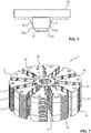
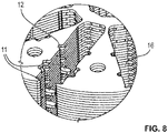
- the 7 and 8th show a laminated rotor core 1 with one-piece laminations 2 according to FIG 3 and with multi-part sheets 3, 4 according to 1 and 2.
- the one-piece and multi-piece sheets 2 and 3 and 4 are in different sequences and according to 7 from bottom to top in partial packets or partial sheet stacks 1a to 1e with a partial packet 1a of, for example, three one-piece sheets 2 according to 3 and a partial laminated core 1b made up of several multi-part sheets 4 according to FIG 2 and a part package 1c made up of several multi-part sheets 3 according to 1 and a partial package 1d, in turn, made up of a plurality of multi-part sheets 4 according to FIG 2 and a partial package 1e with, for example, only one one-piece sheet metal (closing sheet metal) 2 according to FIG 3 stacked.
- the subpackages 1b and 1d are, for example, made up of six to nine or eight multi-piece metal sheets 4 according to FIG 2 formed, while the central part package 1c, for example, from twenty multi-part sheets 3 according to 1 is composed.
- the laminated rotor core 1 is part of a rotor of an electric motor, in particular a drive or adjustment drive of a motor vehicle, in a manner that is not shown in detail.
- FIGS. 4 and 5 show alternative designs of a one-piece and a multi-piece sheet metal 2 'or 4'.
- the multi-part sheet metal 3 shown has a number of sheet metal sections 3a in the shape of a sector of a circle, of which - seen in the circumferential direction of the sheet metal - every second sheet metal section 3a is formed via a sheet metal web 5 on a central, circular sheet metal section 3b with a material recess 6 for the shaft passage of the rotor of the electric motor.
- the remaining sheet metal sections 3c are not connected to the central sheet metal section 3b.
- Each sector-like sheet metal section 3a, 3c forms a partial area of the circular area occupied by the sheet metal 3, delimited by a circular arc 7 and two circle radii 8.
- Some of the sector-like sheet metal sections 3a, 3c have azimuthal or tangential lugs (joining lugs) 11 along their sheet section edges 8, while all sheet metal sections 3a, 3c are provided with notches (joining notches) 12 in the area of their sheet section edges 8.
- the tabs 11 and latches 12 are provided in a specific radial grid, which is that of the latch grid in the Figures 2 to 5 shown sheets 2 to 4 'corresponds.
- azimuthally or tangentially oriented hooks (tangential hooks) 13 are integrally formed or provided which prevent the magnets 10 from slipping out of the recesses 9 radially.
- the sheet metal sections 3a, 3c provided with tabs 11 also have notches 12 at the radially exposed points or positions.
- the remaining sheet metal sections 3a are free of tabs and each have two notches 12 on each of the two circle radii 8 at radially offset positions in the same notch and tab grid.
- All latches 12 and tabs 11 are positioned radially in such a way that tabs 11 and/or latches 12 are always diametrically opposite one another in the region of each recess 9 .
- tabs 11 or notches 12 of all sheet metal sections 3a, 3c are on a circumferential circle with a first radius (first radial or grid position) R 1 or a second radius (second radial or grid position) R 2 .
- the multi-piece sheet 3 according to 1 also has at least one, preferably two radial clamping lugs 14 positioned offset by 180°, which are formed on the central sheet metal section 3b and protrude into the corresponding recess 9. Also, the one-piece sheet 2 'according to 4 two such clamping lugs 14' at diametrically opposed positions.
- Circular material recesses 15 are made in the sector-like sheet metal sections 3a. These are used to reduce the transverse inductance and in particular as an assembly aid or to fix the sheets 2 to 4 'in the stack of sheets 1, for example by means of bolts or the like.
- Each of the lugs 11 is formed by a respective pair of latches 11a, 11b on both sides of the respective lug 11 in the region of the edge 8 of the sheet metal section.
- the lugs 11 are thus punched out of the respective sheet metal section 3a, 3c in the area of the sheet metal section edges 8 by the azimuthal or tangential notches 11a, 11b and extend beyond the circle radius 8 into the respective recess 9.
- This in 2 Multi-part sheet metal 4 shown also has circular sector-like sheet metal sections 4a, which are formed on sheet metal webs 5 on the central, annular sheet metal section 4b, and circular sector-like sheet metal sections 4c, which are not formed on the central sheet metal section 4b.
- the sector-like sheet metal sections 4a, 4c only have 12 notches. These are located at the radial positions R 1 and R 2 according to the grid of the sheet 3 in 1 .
- one-piece sheet metal 2 are all circular sector-like sheet metal sections 2a over sheet metal webs 5 formed on the central sheet metal section 2b.
- all sheet metal sections 2a in the shape of sectors of a circle have only notches 12, which in turn are provided in the same grid with the positions R 1 and R 2 .
- Each of the sector-shaped sheet metal sections of the sheets 2 to 4 occupies a partial area delimited by the circular arc 7 and the two circle radii or sheet-metal section edges 8, which is equal to the partial area of a sector-shaped sheet metal section of the other sheets 2 to 4'. Since the sheet metal sections of the sheets 2 to 4 are identical to one another, the radii 7 and arcs 8 of all sheet metal sections are aligned with one another when the sheets 2 to 4 are in the stacked state.
- the recesses 9 of all the laminations 2 to 4 which are then also aligned with one another, form recesses that extend in the axial direction along the central axis of the laminations (central longitudinal axis). receiving pockets 16 ( 7 ) for the magnets 10 arranged radially within the laminated rotor core 1, i.e. in a star shape.
- At least the laminations 3 provided with tabs 11 are stacked offset or twisted relative to one another by a circular sector angle ⁇ within the rotor laminated core or partial core 1 .
- each receiving pocket 16 there are several tabs 11 in each receiving pocket 16 in the axial direction, which can engage in corresponding notches 12 .
- the corresponding clamping lug 11 deviates axially and clamps or presses the respective magnet against the undercut hook 13 in the area of the circle radii 7.
- the lugs 11 are also bent axially in the course of inserting the magnets 10 and engage or penetrate the axially adjacent, i. H. the latches 12 located underneath in the laminated core 1 or partial stack. In this way, on the one hand, the magnets 10 are clamped and, on the other hand, the laminations 3 of at least the partial laminated core 1c are centered and joined to one another.
- each ratchet 12 shows a preferred embodiment of the or each ratchet 12. Its dimensions are selected in such a way that the corresponding tab 11 engages in this ratchet 12 with excess.
- the latch 12 is preferably trapezoidal, so that the lug 11 protrudes beyond the sloping side flanks 12a of the latch 12 at least with its free-end corner regions 11a. In the course of the bending over and engagement of the tab 11 in the latch 12, at least the tab 11 is deformed. However, mutual deformation is preferred reached by tab 11 and notch 12. This leads to a particularly reliable joint between the relevant, axially adjacent metal sheets 3 or sheet metal sections 3a, 3c.
Landscapes
- Engineering & Computer Science (AREA)
- Power Engineering (AREA)
- Mechanical Engineering (AREA)
- General Engineering & Computer Science (AREA)
- Permanent Field Magnets Of Synchronous Machinery (AREA)
- Iron Core Of Rotating Electric Machines (AREA)
- Manufacture Of Motors, Generators (AREA)
Description
- Die Erfindung betrifft ein Rotorblechpaket für einen Elektromotor, mit einer Mehrzahl von axial zusammengesetzten mehrteiligen und/oder einteiligen Blechen mit kreissektorartigen Blechabschnitten, zwischen denen radiale und umfangsseitig offene Ausnehmungen zur Aufnahme jeweils eines Magneten gebildet sind.
- Elektromotoren mit derartigen Blechpaketen sind als Kleinmotoren häufig im Kraftfahrzeugbereich und dort insbesondere als Lenkungsmotoren oder in Verstellantrieben eingesetzt. Während bei einem Elektromotor als so genannter Außenläufermotor der Rotor den feststehenden Stator konzentrisch umgibt, ist bei einem Innenläufermotor der Stator unter Bildung eines Luftspaltes koaxial zum rotierenden Läufer (Rotor) angeordnet.
- Bei einem permanent erregten bürstenlosen Gleichstrommotor trägt der Rotor eine Anzahl von Dauer- oder Permanentmagneten, während der Stator eine beispielsweise dreiphasig verschaltete Spulenwicklung umfasst, die über pulsseitenmodulierte Ströme angesteuert wird. Ist dabei der Rotor mit den Magneten versehen, so können diese durch Klemmung und/oder Verklebung am Blechpaket des Rotors gehalten sein. Das Blechpaket besteht aus einer Vielzahl von stanzpaketierten Einzelblechen (Blechlaminate).
- Aus der
EP 1 223 658 A1 und aus derDE 10 2007 024 406 A1 ist es bekannt, ein Rotorblechpaket aus ein- und mehrstückigen oder -teiligen Blechen mit kreissektorartigen Blechabschnitten zusammenzusetzen. Hierzu weist ein erster einstückiger (einteiliger) Blechtyp innen- und/oder außenumfangsseitig stegartige Verbindungsbereiche zwischen den Blechabschnitten auf. Ein zweiter mehrstückiger (mehrteiliger) Blechtyp besteht praktisch aus den einzelnen, untereinander nicht verbunden Blechabschnitten. Die Verbindung der axial gestapelten Bleche untereinander erfolgt nach Art einer Stanzpaketierung mittels in die Blechabschnitte eingestanzten, ineinandergreifende (sickenartige) Ausnehmungen und Vorsprünge. Zwischen den Blechabschnitten sind radiale, umfangsseitig offene Ausnehmungen gebildet, die im paketierten Blechstapel axial fluchten und Aufnahmetaschen für Permanentmagnete bilden. - Aus der
DE 103 57 502 A1 ist ein Rotor bekannt, der sich in axialer Richtung aus einem Blechpaket aus identisch geformten Einzelblechen zusammensetzt, wobei in Aufnahmetaschen des Rotors eingesetzte Magnete mittels an den Schmalseiten der Aufnahmetaschen vorgesehenen Nasen gehalten sind. - Bei dem aus der
DE 10 2007 029 719 A1 bekannten Blechpaket tragen Taschenöffnungen von Einzelblechen entweder an beiden Schmalseiten oder an nur einer, jedoch stets an der gleichen Schmalseite eine Klemmlasche. - Aus der
US 5,581,140 ist ebenfalls ein aus Einzelblechen gestapelter Rotor mit Aufnahmetaschen für Magnete bekannt. An den Längsseiten der Aufnahmetaschen sind Klemmlaschen zur Klemmfixierung der Magnete vorgesehen, wobei die Klemmlaschen nicht in jeder Blechlage, sondern lediglich in jeder dritten oder vierten Blechlage vorgesehen sind. - Aus der
JP 2011 172441 A - Die
DE 10 2010 030 326 A1 offenbart ein Rotorpaket mit übereinander angeordneten Rotorblechen. Im Rotorpaket sind Taschen ausgebildet, in welche Magnete aufgenommen werden können. Eines der Bleche weist Klemmnasen auf, die in die Taschen hineinragen. - Der Erfindung liegt die Aufgabe zugrunde, ein Rotorblechpaket der eingangs genannten Art zu verbessern. Insbesondere soll in einfacher Weise eine zuverlässige Halterung der Bleche untereinander sowie insbesondere der Magnete innerhalb des Blechpakets ermöglicht werden.
- Diese Aufgabe wird erfindungsgemäß gelöst durch die Merkmale des Anspruchs 1. Vorteilhafte Ausgestaltungen und Weiterbildungen sind Gegenstand der Unteransprüche.
- Hierzu ist das erfindungsgemäße Rotorblechpaket für einen Elektromotor aus einer Mehrzahl von Blechen mit radialen Ausnehmungen zur Bildung von Aufnahmetaschen für jeweils ein Magnet (Permanentmagnet) zusammengesetzt, d. h. axial übereinander angeordnet (gestapelt). Dabei sind eine vorgebbare erste Anzahl von einstückigen, d. h. einteiligen Blechen und eine vorgebbare zweite Anzahl von mehrstückigen bzw. mehrteiligen Blechen, jeweils mit kreissektorartigen Blechabschnitten vorgesehen. Jeder dieser Blechabschnitte nimmt einen Kreissektor (Kreisausschnitt) und damit eine Teilfläche der Kreisfläche des jeweiligen Bleches ein, wobei jeder Blechabschnitt von einem Kreisbogen und zwei Kreisradien begrenzt ist, die ihrerseits eine der Magnetausnehmungen radial begrenzen.
- Die einteiligen Bleche weisen innenumfangsseitig vorzugsweise einen Blechabschnitt mit zentraler Materialausnehmung zur Wellendurchführung auf. An diesen kreisringförmigen Blechabschnitt sind die kreissektorartigen Blechabschnitte der einteiligen Bleche über Blechstege speichenartig angeformt. Auch die mehrteiligen Bleche weisen vorzugsweise innenumfangsseitig einen mit einer zentralen Materialausnehmung zur Wellendurchführung versehenen Blechabschnitt auf, an den zumindest einige der kreissektorartigen Blechabschnitte, vorzugsweise in Blechumfangsrichtung jeder zweite Blechabschnitt, über Blechstege angeformt sind.
- Die kreissektorartigen Blechabschnitte aller Bleche sind hinsichtlich deren Sektorengröße praktisch gleich, so dass die zwischen deren Kreisradien verbleibenden Ausnehmungen im gestapelten Blechpaket axial fluchten und radiale Aufnahmetaschen für die Permanentmagnete bilden. Eine vorgebbare Anzahl der Blechabschnitte, vorzugsweise lediglich der mehrteiligen Bleche, weist kreisradiusseitig d. h. entlang der Kreisradien der jeweiligen Blechabschnitte mindestens eine, vorzugsweise zwei axial biegbare Laschen auf. Die jeweilige Lasche ragt in die von diesem Kreisradius bzw. dieser Blechabschnittskante begrenzte Magnetausnehmung hinein.
- Jede der axial biegbaren Laschen (Fügelasche) jedes entsprechenden kreissegmentartigen Blechabschnitts des jeweiligen Bleches ist zweckmäßigerweise gebildet durch zwei in die Blechabschnittskante - also kreisradiusseitig - eingebrachte Klinkungen, welche die jeweilige Lasche beidseitig flankieren. Die jeweilige Lasche verläuft azimutal, d. h. in Blechumfangsrichtung und überragt die jeweilige kreisradiusseitige Blechabschnittskante des entsprechenden Blechabschnitts. Die Laschen bzw. Fügelaschen sind somit im Zuge des Stanzprozesses in einfacher Art und Weise herstellbar und in den entsprechenden kreissegmentartigen Blechabschnitt einbringbar.
- In vorteilhafter Ausgestaltung sind nur einige der kreissektorartigen Blechabschnitte mit derartigen Laschen versehen. Vorzugsweise mindestens zwei Blechabschnitte, die nachfolgend als Blechabschnittspaar bezeichnet werden, weisen an einem der beiden Kreisradien bzw. Blechabschnittskanten jeweils eine Lasche auf. Besonders bevorzugt sind ein- oder zweimal zwei direkt benachbarte Blechabschnittspaare vorgesehen, von denen ein Blechabschnitt beiden Blechabschnittspaaren zugeordnet ist und beidseitig an dessen Kreisradien bzw. Blechabschnittskanten jeweils eine Lasche aufweist. Diese beiden Laschen sind an radial versetzten Positionen entlang des jeweiligen Kreisradius angeordnet. Die beiden zu diesem mittleren, zwei Laschen aufweisenden Blechabschnitt benachbarten Blechabschnitte weisen am dem mittleren Blechabschnitt zugewandten Kreisradius jeweils nur eine einzelne Lasche auf, die der gegenüberliegenden Lasche des mittleren Blechabschnitts tangential bzw. azimutal direkt gegenüberliegend vorgesehen ist.
- Zweckmäßigerweise weist jeder kreissektorartige Blechabschnitt des jeweiligen einstückigen Bleches mindestens eine Klinkung (Fügeklinkung) und vorzugsweise an jedem Kreisradius jeweils mindestens eine Klinkung bzw. Fügeklinkung auf. Besonders bevorzugt weisen diejenigen kreissektorartigen Blechabschnitte des jeweiligen Blechs an jedem Kreisradius zwei Klinkungen auf, die den Klinkungen eines benachbarten Blechabschnitts azimutal bzw. tangential direkt gegenüber liegen. Die Laschen und Klinkungen aller kreissektorartigen Blechabschnitte jedes Blechtyps (ein- oder mehrteilig) befinden sich stets in ein und demselben Raster, so dass innerhalb des Rotorblechpaketes Laschen und Klinkungen stets axial übereinander angeordnet sind und somit axial fluchten.
- Dadurch ist erreicht, dass eine im Zuge des Einsetzens eines Magnets in die entsprechende, durch die Ausnehmungen der Einzelbleche gebildete Aufnahmetasche des Rotorblechpaketes axial gebogene Lasche stets in eine oder mehrere axial darunter liegende Klinkungen eingreift, in diese also ausweichen kann. Die Laschen dringen hierbei zumindest teilweise in die darunter befindlichen Klinkungen ein, was einen besonders vorteilhaften Zusammenhalt der betroffenen Bleche und einzelnen Blechabschnitte im Rotorblechpaket (Blechstapel) bewirkt. Die Laschen und Klinkungen übernehmen somit eine Mehrfachfunktion, nämlich einerseits ein Klemmfixierung der Magnete in den Aufnahmetaschen und andererseits den Zusammenhalt der betroffenen Bleche bzw. Blechabschnitte. Eine weitere Funktion der Laschen und Klinkungen ist die Zentrierung der Bleche oder Blechabschnitte innerhalb des Blechpaketes oder Teilblechstapels.
- Werden im Zuge des Stapelns die Bleche von Blechlage zu Blechlage um einen Kreissegmentwinkel gegeneinander versetzt oder verdreht, so fluchten bei allen aufeinanderliegenden Blechabschnitten stets Laschen mit korrespondierenden Klinkungen, in welche die Laschen axial eingebogen werden können. Auf diese Art werden alle beispielsweise in einem entsprechenden Blechteilstapel enthaltenen Bleche miteinander gefügt sowie aneinander verdrehsicher gehalten, zentriert und gegen ein radiales Verschieben gegeneinander gesichert. Aufgrund der Ausbildung der kreissektorartigen Blechabschnitte mit Laschen und/oder Klinkungen können einteilige und mehrteilige Bleche in axial unterschiedlichen Abfolgen gestapelt sein sowie in Gruppen oder Teilpaketen verschiedener Kombinationen von ein- und mehrteiligen Blechen miteinander gefügt werden.
- In dem auf diese Art und Weise gebildeten Blechpaket fluchten die Ausnehmungen zwischen den kreissektorartigen Blechabschnitten der Bleche miteinander und bilden die sich in Axialrichtung erstreckenden Aufnahmetaschen für die Permanentmagnete. Deren Halterung innerhalb dieser Aufnahmetaschen erfolgt durch Klemmfixierung mittels der Laschen. Dabei sind aufgrund gezielt in Paketumfangsrichtung gedrehter Blechanordnung alle Aufnahmetaschen mit einer Anzahl von Laschen versehen. Zusätzlich sind vorzugsweise an zumindest einigen der innerhalb des Blechpakets gestapelten Bleche, insbesondere an den mehrteiligen Blech, weitere Laschen (Klemmlaschen) vorgesehen, die an den kreisförmigen Blechringabschnitt, d. h. den kreisringförmigen Blechabschnitt mit zentraler Materialaussparung zur Wellendurchführung des jeweiligen Bleches angeformt sind und radial in die entsprechende Ausnehmung dieses Bleches hineinragen. Geeigneterweise weist jedes dieser Bleche lediglich zwei derartige Klemmlaschen auf, die einander diametral gegenüberliegend angeordnet sind.
- Wenn die Bleche gegeneinander versetzt bzw. um die zentrale Blechachse verdreht gestapelt werden, entspricht der Kreissektorwinkel oder der Dreh- bzw. Versatzwinkel demjenigen Bruchteil von 360°, den die von einem kreissektorartigen Blechabschnitt und einer Ausnehmung gebildete Teilfläche beansprucht. Bei einer Blechanordnung mit beispielsweise zehn kreissektorartigen Blechabschnitten - und somit bei einem Rotorblechpaket zur Aufnahme von zehn Magneten - beträgt der Kreissektorwinkel 36°. Unter Zugrundelegung einer solchen Teilung können bei der Bildung eines Blech- oder Teilblechpakets mehrere Bleche gegeneinander um einen Kreissektorwinkel von 36° versetzt gestapelt und mittels der Laschen und Klinkungen miteinander gefügt werden. Dabei sind alle beteiligten und jeweils übereinander angeordneten kreissektorartigen Blechabschnitte mit einer minimalen, jedoch ausreichenden Anzahl von Laschen zuverlässig aneinander gehalten. Infolge der gezielten Positionierung der Laschen und Klinkungen ist hierbei eine Kollision der Laschen vermieden.
- Nachfolgend werden Ausführungsbeispiele der Erfindung anhand einer Zeichnung erläutert. Darin zeigen:
- Fig. 1
- in Draufsicht eine Hälfte eines mehrteiligen Blechs mit kreissektorartigen Blechabschnitten sowie Laschen (Fügelaschen) und Klinkungen (Fügeklinkungen),
- Fig. 2
- in einer Darstellung gemäß
Fig. 1 ein mehrteiliges Blech aus einer entsprechenden Anzahl kreissektorartiger Blechabschnitte mit Klinkungen (Fügeklinkungen), - Fig. 3
- in einer Darstellung gemäß
Fig. 1 ein einteiliges Blech aus einer entsprechenden Anzahl kreissektorartiger Blechabschnitte mit Klinkungen (Fügeklinkungen), - Fig. 4
- in Draufsicht ein einteiliges Blech aus kreissektorartigen Blechabschnitten mit Laschen (Fügelaschen) und Klinkungen (Fügeklinkungen),
- Fig. 5
- in Draufsicht ein mehrteiliges Blech aus einer entsprechenden Anzahl kreissektorartigen Blechabschnitten mit Klinkungen (Fügeklinkungen),
- Fig. 6
- schematisch ein Fügeverbindung zwischen sich verformender Lasche und Klinkung unter Einwirkung eines Permanentmagneten,
- Fig. 7
- perspektivisch ein Rotorblechpaket aus Teilblechpaketen, und
- Fig. 8
- das Rotorblechpaket ausschnittsweise in größerem Maßstab.
- Einander entsprechende Teile sind in allen Figuren mit den gleichen Bezugszeichen versehen.
- Die
Fig. 7 und8 (ausschnittsweise) zeigen ein Rotorblechpaket 1 mit einteiligen Blechen 2 gemäßFig. 3 sowie mit mehrteiligen Blechen 3, 4 gemäß denFig. 1 bzw. 2. Die ein- und mehrteiligen Bleche 2 bzw. 3 und 4 sind in unterschiedlichen Abfolgen und dabei gemäßFig. 7 von unten nach oben in Teilpaketen oder Teilblechstapeln 1a bis 1e mit einem Teilpaket 1a aus beispielsweise drei einteiligen Blechen 2 gemäßFig. 3 und einem Teilblechpaket 1b aus mehreren mehrteiligen Blechen 4 gemäßFig. 2 sowie einem Teilpaket 1c aus mehreren mehrteiligen Blechen 3 gemäßFig. 1 und einem Teilpakete 1d aus wiederum mehreren mehrteiligen Blechen 4 gemäßFig. 2 sowie einem Teilpaket 1e mit beispielsweise nur einem einteiligen Blech (Abschlussblech) 2 gemäßFig. 3 gestapelt. - Die Teilpakete 1b und 1d sind beispielsweise aus sechs bis neun bzw. aus acht mehrteiligen Blechen 4 gemäß
Fig. 2 gebildet, während das mittlere Teilpaket 1c beispielsweise aus zwanzig mehrteiligen Blechen 3 gemäßFig. 1 zusammengesetzt ist. Das Rotorblechpaket 1 ist in nicht näher dargestellter Art und Weise Bestandteil eines Rotors eines Elektromotors, insbesondere eines Antriebs oder Verstellantriebs eines Kraftfahrzeugs. - Die
Fig. 4 und 5 zeigen alternative Ausführungen eines einteiligen und eines mehrteiligen Blechs 2' bzw. 4'. - Das in
Fig. 1 gezeigte mehrteilige Blech 3 weist eine Anzahl von kreissektorartigen Blechabschnitten 3a auf, von denen - in Blechumfangsrichtung gesehen - jeder zweite Blechabschnitt 3a über einen Blechsteg 5 an einen zentralen, kreisringförmigen Blechabschnitt 3b mit einer Materialaussparung 6 zur Wellendurchführung des Rotors des Elektromotors angeformt ist. Die verbleibenden Blechabschnitte 3c sind nicht mit dem zentralen Blechabschnitt 3b verbunden. Jeder kreissektorartige Blechabschnitt 3a, 3c bildet eine von einem Kreisbogen 7 und zwei Kreisradien 8 begrenzte Teilfläche der von dem Blech 3 eingenommenen Kreisfläche. Die nachfolgend auch als Blechabschnittskanten bezeichneten Kreisradien 8 begrenzen jeweils eine radiale Ausnehmung 9 für im Rotorblechpaket 1 radial angeordnete Permanentmagnete (Radialmagnete), von denen inFig. 6 ein Magnet 10 dargestellt ist. - Einige der kreissektorartigen Blechabschnitte 3a, 3c weisen entlang deren Blechabschnittskanten 8 azimutale oder tangentiale Laschen (Fügelaschen) 11 auf, während alle Blechabschnitte 3a, 3c im Bereich deren Blechabschnittskanten 8 mit Klinkungen (Fügeklinkungen) 12 versehen sind. Die Laschen 11 und Klinkungen 12 sind in einem bestimmten radialen Raster vorgesehen, welches demjenigen Klinkungsraster der in den
Figuren 2 bis 5 gezeigten Bleche 2 bis 4' entspricht. Im Bereich des Kreisbogens 7 des jeweiligen Blechabschnitts 3a, 3c sind an diesen azimutal bzw. tangential orientierte Haken (Tangentialhaken) 13 angeformt bzw. vorgesehen, die ein radiales Ausgleiten der Magnete 10 aus den Ausnehmungen 9 verhindern. - Erkennbar weisen nur einige der sektorartigen Blechabschnitte 3a derartige Laschen 11 auf. Lediglich zwei Gruppen mit jeweils drei direkt benachbarten Blechabschnitten 3a, 3c und somit insgesamt sechs Blechabschnitte 3a, 3c in vier Blechabschnittspaaren weisen jeweils eine Lasche 11 oder zwei Laschen 12 auf.
- In
Fig. 1 ist nur eine solche Gruppe mit drei direkt benachbarten und Laschen 11 aufweisenden Blechabschnitten 3a, 3c dargestellt, während die zweite Gruppe der nicht dargestellten zweiten Hälfte des Bleches 3 zugeordnet ist. Die mit zwei Laschen 11 versehenen Blechabschnitte 3a weisen an beiden Kreisradien 8 jeweils eine Lasche 11 auf, die zueinander radial versetzt sind. An dieser radialen Position befinden sich wiederum diametral gegenüberliegend die Laschen 11 der benachbarten Blechabschnitte 3c. - Die mit Laschen 11 ausgeführten Blechabschnitte 3a, 3c weisen an den radial exponierten Stellen bzw. Positionen ebenfalls Klinkungen 12 auf. Die übrigen Blechabschnitte 3a sind laschenfrei und weisen an jeweils beiden Kreisradien 8 jeweils zwei Klinkungen 12 an radial versetzten Positionen im gleichen Klinkungs- und Laschenraster auf. Dabei sind alle Klinkungen 12 und Laschen 11 derart radial positioniert, dass sich im Bereich einer jeden Ausnehmung 9 stets Laschen 11 und/oder Klinkungen 12 diametral gegenüberliegen. Mit anderen Worten befinden sich Laschen 11 bzw. Klinkungen 12 aller Blechabschnitte 3a, 3c auf einem Umfangskreis mit einem ersten Radius (erste Radial- oder Rasterposition) R1 oder einem zweiten Radius (zweite Radial- bzw. Rasterposition) R2.
- Das mehrteilige Blech 3 gemäß
Fig. 1 weist zudem mindestens eine, vorzugsweise zwei um180° versetzt positionierte radiale Klemmlasche 14 auf, die an den zentralen Blechabschnitt 3b angeformt sind und in die entsprechende Ausnehmung 9 hineinragen. Auch kann das einstückige Blech 2' gemäßFig. 4 zwei derartige Klemmlaschen 14' an diametral gegenüberliegenden Positionen aufweisen. - In die sektorartigen Blechabschnitte 3a sind kreisrunde Materialausnehmungen 15 eingebracht. Diese dienen zur Reduzierung der Querinduktivität und insbesondere als Montagehilfe bzw. zur Fixierung der Bleche 2 bis 4' im Blechstapel 1, beispielsweise mittels Schraubbolzen oder dergleichen.
- Jede der Laschen 11 ist durch jeweils ein Klinkungspaar 11a, 11b beidseitig der jeweiligen Lasche 11 im Bereich der Blechabschnittskante 8 gebildet. Die Laschen 11 sind somit im Bereich der Blechabschnittskanten 8 durch die azimutalen bzw. tangentialen Klinkungen 11a, 11b aus dem jeweiligen Blechabschnitt 3a, 3c ausgestanzt und erstrecken sich über den Kreisradius 8 hinaus in die jeweilige Ausnehmung 9 hinein.
- Das in
Fig. 2 dargestellte mehrteilige Blech 4 weist ebenfalls kreissektorartige Blechabschnitte 4a, die über Blechstege 5 an den zentralen, ringförmigen Blechabschnitt 4b angeformt sind, sowie kreissektorartige Blechabschnitte 4c auf, die nicht an den zentralen Blechabschnitt 4b angeformt sind. Die kreissektorartigen Blechabschnitte 4a, 4c weisen lediglich Klinkungen 12 auf. Diese befinden sich an den radialen Positionen R1 und R2 gemäß dem Raster des Blechs 3 inFig. 1 . - Bei dem in
Fig. 3 dargestellten einteiligen Blech 2 sind alle kreissektorartigen Blechabschnitte 2a über Blechstege 5 an den zentralen Blechabschnitt 2b angeformt. Auch bei diesem Blechtyp weisen alle kreissektorartigen Blechabschnitte 2a lediglich Klinkungen 12 auf, die wiederum im gleichen Raster mit den Positionen R1 und R2 vorgesehen sind. - Jeder der kreissektorartigen Blechabschnitte der Bleche 2 bis 4 nimmt eine von dem Kreisbogen 7 und den beiden Kreisradien bzw. Blechabschnittskanten 8 begrenzte Teilfläche ein, die gleich der Teilfläche eines kreissektorartigen Blechabschnitts der anderen Bleche 2 bis 4' ist. Da die Blechabschnitte der Bleche 2 bis 4 untereinander gleich sind, fluchten die Kreisradien 7 und Kreisbögen 8 aller Blechabschnitte in gestapeltem Zustand der Bleche 2 bis 4 miteinander. Die dann ebenfalls miteinander fluchtenden Ausnehmungen 9 aller Bleche 2 bis 4 bilden sich in Axialrichtung entlang der Blechpaketmittelachse (Mittellängsachse) erstreckende Aufnahmetaschen 16 (
Fig. 7 ) für die innerhalb des Rotorblechpaketes 1 radial, d. h. sternförmig angeordneten Magnete 10. - Innerhalb des Rotorblechpaketes oder-teilpaketes 1 sind zumindest die mit Laschen 11 versehenen Bleche 3 um einen Kreissektorwinkel α gegeneinander versetzt oder verdreht gestapelt. Der Kreissektorwinkel α beträgt 360° geteilt durch die Anzahl a der Blechabschnitte 3a, 3c (a = 360°/a). Bei gemäß dem Ausführungsbeispiel insgesamt zehn Blechabschnitten 3a, 3c (a = 10) beträgt der Kreissektorwinkel α = 36°.
- Werden fünf derartige Bleche 3 um jeweils diesen Kreissektorwinkel α in der gleichen Drehrichtung gegeneinander versetzt, so befinden sich einerseits in jeder Aufnahmetasche 16 in Axialrichtung mehrere Laschen 11, die in korrespondierende Klinkungen 12 eingreifen können. Andererseits befindet sich in jeder Aufnahmetasche 16 mindestens eine radiale Klemmlasche 14, jedoch in axial unterschiedlicher Position bzw. Ebene, wie aus den
Fig. 7 und8 hervorgeht. - Beim Einstecken der Permanentmagnete 10 in die jeweilige Aufnahmetasche 14 weicht die entsprechende Klemmlasche 11 axial aus und klemmt bzw. drückt den jeweiligen Magneten gegen die hinterschnittenen Haken 13 im Bereich der Kreisradien 7. Ebenso werden die Laschen 11 im Zuge des Einsetzens der Magnete 10 axial abgebogen und greifen oder dringen in die axial benachbarten, d. h. die im Blechpaket 1 oder Teilstapel darunter befindlichen Klinkungen 12 ein. Hierdurch werden einerseits die Magnete 10 klemmfixiert sowie andererseits die Bleche 3 zumindest des Teilblechpakets 1c zentriert und miteinander gefügt.
-
Fig. 6 zeigt eine bevorzugte Ausführungsform der oder jeder Klinkung 12. Deren Abmessungen sind derart gewählt, dass die entsprechende Lasche 11 mit Übermaß in diese Klinkung 12 eingreift. Bevorzugt ist die Klinkung 12 trapezförmig ausgebildet, so dass die Lasche 11 zumindest mit deren freiendseitigen Eckbereichen 11a die schrägen Seitenflanken 12a der Klinkung 12 überragen. Im Zuge des Umbiegens und Eingreifens der Lasche 11 in die Klinkung 12 wird zumindest die Lasche 11 verformt. Vorzugsweise wird jedoch eine gegenseitige Verformung von Lasche 11 und Klinkung 12 erreicht. Dies führt zu einer besonders zuverlässigen Fügeverbindung zwischen den betroffenen, axial benachbarten Blechen 3 bzw. Blechabschnitten 3a, 3c. - Die Erfindung ist nicht auf das vorstehend beschriebene Ausführungsbeispiel beschränkt. Vielmehr können im Rahmen des durch die Ansprüche definierten Schutzbereichs auch anderen Varianten der Erfindung von dem Fachmann hieraus abgeleitet werden, ohne den Gegenstand der Erfindung zu verlassen.
-
- 1
- Rotorblechpaket
- 1a-e
- Teilpaket/-blechstapel
- 2
- einteiliges Blech
- 2a
- kreissektorartiger Blechabschnitt
- 2b
- kreisringförmiger Blechabschnitt
- 3
- mehrteiliges Blech
- 3a
- kreissektorartiger Blechabschnitt
- 3b
- ringförmiger Blechabschnitt
- 3c
- kreissektorartiger Blechabschnitt
- 4
- mehrteiliges Blech
- 4a
- kreissektorartiger Blechabschnitt
- 4b
- ringförmiger Blechabschnitt
- 4c
- kreissektorartiger Blechabschnitt
- 5
- Blechsteg
- 6
- Materialaussparung
- 7
- Kreisbogen
- 8
- Kreisradius/Blechabschnittskante
- 9
- Ausnehmung
- 10
- Magnet
- 11
- Füge-/Lasche
- 11a,b
- Klinkungspaar
- 12
- Füge-/Klinkung
- 13
- Tangential-/Haken
- 14
- Klemmlasche
- 15
- Materialausnehmung
- 16
- Aufnahmetasche
- R1,2
- Radialposition
- α
- Kreissektorwinkel
Claims (10)
- Rotorblechpaket (1) für einen Elektromotor, mit einer Mehrzahl von axial zusammengesetzten mehrteiligen und/oder einteiligen Blechen (2,2',3,3',4) mit kreissektorartigen Blechabschnitten (2a,2a',3a,3a',3c,4a,4c), zwischen denen radiale und umfangsseitig offene Ausnehmungen (9) zur Aufnahme jeweils eines Magneten (10) gebildet sind,- wobei die kreissektorartigen Blechabschnitte (2a,2a',3a,3a',3c,4a,4c) aller Bleche (2,2',3,3',4) hinsichtlich deren Sektorengröße praktisch gleich sind, so dass die zwischen deren Blechabschnittskanten (8) verbleibenden Ausnehmungen (9) im gestapelten Blechpaket axial fluchten und radiale Aufnahmetaschen (16) für die Magnete (10) bilden, dadurch gekennzeichnet,- dass eine vorgebbare Anzahl der kreissektorartigen Blechabschnitte (3a, 3c) der einteiligen bzw. der mehrteiligen Bleche (2',3) entlang mindestens einer kreisradiusseitigen Blechabschnittskante (8) mindestens eine azimutale Lasche (11) aufweisen, die in die von der Blechabschnittskante (8) begrenzte Ausnehmung (9) hineinragt und im Zuge des Einsetzens des entsprechenden Magneten (10) in die jeweilige Ausnehmung (9) axial biegbar ist,- wobei die kreissektorartigen Blechabschnitte (3a, 3c) der einteiligen bzw. mehrteiligen Bleche (2,2',3,3',4) kreisradiusseitig mindestens eine Klinkung (12) aufweisen, in welche die hiermit korrespondierende Lasche (11) des Blechabschnitts (3a, 3c) eines axial beabstandeten Blechs (3) in Folge der axialen Biegung eingreift,- wobei sich die Laschen (11) und die Klinkungen (12) aller kreissektorartigen Blechabschnitte (3a, 3c) der einteiligen Bleche (2) und der mehrteiligen Bleche (3, 4) stets in ein und demselben Raster befinden, so dass innerhalb des Rotorblechpaketes Laschen (11) und Klinkungen (12) stets axial übereinander angeordnet sind und somit axial fluchten, und- wobei benachbarte kreissektorartige Blechabschnitte (3a, 3c) mindestens eines Blechabschnittspaars der einteiligen bzw. mehrteiligen Bleche (2',3) jeweils eine solche Lasche (11) aufweisen, welche innerhalb der entsprechenden Ausnehmungen (9) einander gegenüber positioniert sind.
- Rotorblechpaket (1) nach Anspruch 1,
dadurch gekennzeichnet,
dass die Laschen (11) der kreissektorartigen Blechabschnitte (3a, 3c) benachbarter Blechlaschenpaare radial versetzt positioniert sind. - Rotorblechpaket (1) nach Anspruch 1 oder 2,
dadurch gekennzeichnet,
dass benachbarte kreissektorartige Blechabschnitte (3a, 3c) eines geradzahligen Vielfachen von zwei Blechabschnittspaaren der mehrteiligen Bleche (3) jeweils eine Lasche (11) aufweisen. - Rotorblechpaket (1) nach einem der Ansprüche 1 bis 3,
dadurch gekennzeichnet,
dass die axial biegbare Lasche (11) jedes kreissektorartigen Blechabschnitts (3a, 3c) durch zwei in diesen kreisradiusseitig und beidseitig der Lasche (11) eingebrachte Klinkungen (11a, 11b) gebildet ist. - Rotorblechpaket (1) nach einem der Ansprüche 1 bis 4,
dadurch gekennzeichnet,
dass die einteiligen Bleche (2) einen eine Materialaussparung (6) zur Wellendurchführung bildenden zentralen Blechabschnitt (2b) aufweisen, an den die kreissektorartigen Blechabschnitte (2a) über Blechstege (5) angeformt sind. - Rotorblechpaket (1) nach einem der Ansprüche 1 bis 5,
dadurch gekennzeichnet,
dass die mehrteiligen Bleche (3, 4) einen eine Materialaussparung (6) zur Wellendurchführung bildenden zentralen Blechabschnitt (3b, 4b) aufweisen, an welchen mindestens ein, vorzugsweise jeder zweite, kreissektorartige Blechabschnitt (3a, 4a) über einen Blechsteg (5) angeformt ist. - Rotorblechpaket (1) nach einem der Ansprüche 1 bis 6,
dadurch gekennzeichnet,
dass eine vorgebbare Anzahl der Bleche (2 bis 4), insbesondere der mehrteiligen Bleche (3), an deren zentralen Blechabschnitt (3b) mindestens eine radiale Klemmlasche (14), vorzugsweise genau zwei einander diametral gegenüber angeordnete radiale Klemmlaschen (14), zur Klemmfixierung der Magnete (10), aufweist. - Rotorblechpaket (1) nach einem der Ansprüche 1 bis 7,
dadurch gekennzeichnet,
dass die Bleche (2 bis 4), insbesondere die mit Laschen (11) versehenen Bleche (3), um mindestens einen Kreissektorwinkel (α) gegeneinander verdreht gestapelt sind. - Rotorblechpaket (1) nach einem der Ansprüche 1 bis 8, wobei die Bleche (2 bis 4) in mindestens drei Teilblechpaketen (1a bis 1e) gestapelt sind,
dadurch gekennzeichnet,- dass ein erstes und ein drittes Teilblechpaket (1b, 1d) lediglich aus mehrteiligen Blechen (4) ohne Laschen zusammengesetzt sind, und- dass ein axial zwischen dem ersten und dritten Teilblechpaket (1b bzw. 1d) vorgesehenes zweites Teilblechpaket (1c) aus mehrteiligen Blechen (3) mit Laschen (11) zusammengesetzt ist. - Rotorblechpaket (1) nach Anspruch 9,
gekennzeichnet durch
mindestens ein stirnseitig, vorzugsweise beidseitig, der Teilblechpakete (1b, 1c, 1d) vorgesehenes einteiliges Blech (2), insbesondere ohne Laschen.
Applications Claiming Priority (3)
| Application Number | Priority Date | Filing Date | Title |
|---|---|---|---|
| DE102011122023A DE102011122023A1 (de) | 2011-12-23 | 2011-12-23 | Roboterblechpaket eines Elektromotors |
| EP12816239.3A EP2795764B1 (de) | 2011-12-23 | 2012-12-14 | Rotorblechpaket eines elektromotors |
| PCT/EP2012/005168 WO2013091803A2 (de) | 2011-12-23 | 2012-12-14 | Rotorblechpaket eines elektromotors |
Related Parent Applications (2)
| Application Number | Title | Priority Date | Filing Date |
|---|---|---|---|
| EP12816239.3A Division EP2795764B1 (de) | 2011-12-23 | 2012-12-14 | Rotorblechpaket eines elektromotors |
| EP12816239.3A Division-Into EP2795764B1 (de) | 2011-12-23 | 2012-12-14 | Rotorblechpaket eines elektromotors |
Publications (3)
| Publication Number | Publication Date |
|---|---|
| EP3499689A2 EP3499689A2 (de) | 2019-06-19 |
| EP3499689A3 EP3499689A3 (de) | 2019-06-26 |
| EP3499689B1 true EP3499689B1 (de) | 2022-05-11 |
Family
ID=47563329
Family Applications (3)
| Application Number | Title | Priority Date | Filing Date |
|---|---|---|---|
| EP12816239.3A Active EP2795764B1 (de) | 2011-12-23 | 2012-12-14 | Rotorblechpaket eines elektromotors |
| EP19154569.8A Active EP3499689B1 (de) | 2011-12-23 | 2012-12-14 | Rotorblechpaket eines elektromotors |
| EP19154559.9A Withdrawn EP3499688A3 (de) | 2011-12-23 | 2012-12-14 | Rotorblechpaket eines elektromotors |
Family Applications Before (1)
| Application Number | Title | Priority Date | Filing Date |
|---|---|---|---|
| EP12816239.3A Active EP2795764B1 (de) | 2011-12-23 | 2012-12-14 | Rotorblechpaket eines elektromotors |
Family Applications After (1)
| Application Number | Title | Priority Date | Filing Date |
|---|---|---|---|
| EP19154559.9A Withdrawn EP3499688A3 (de) | 2011-12-23 | 2012-12-14 | Rotorblechpaket eines elektromotors |
Country Status (7)
| Country | Link |
|---|---|
| US (1) | US9306422B2 (de) |
| EP (3) | EP2795764B1 (de) |
| KR (1) | KR101738882B1 (de) |
| CN (1) | CN104011975B (de) |
| BR (1) | BR112014014938A2 (de) |
| DE (1) | DE102011122023A1 (de) |
| WO (1) | WO2013091803A2 (de) |
Families Citing this family (49)
| Publication number | Priority date | Publication date | Assignee | Title |
|---|---|---|---|---|
| DE102013218769A1 (de) * | 2013-09-19 | 2015-03-19 | Siemens Aktiengesellschaft | Rotor sowie Verfahren zum Herstellen eines Rotors |
| US9621001B2 (en) * | 2013-10-23 | 2017-04-11 | GM Global Technology Operations LLC | Rotor assembly for electric machine having mechanical retention system for magnets |
| DE102013226379A1 (de) * | 2013-12-18 | 2015-06-18 | Robert Bosch Gmbh | Elektrische Maschine mit jeweils zumindest zwei Klemmnasen zur Befestigung eines Dauermagneten |
| EP2942857A1 (de) * | 2014-05-07 | 2015-11-11 | Pierburg Pump Technology GmbH | Elektrisches Kfz-Nebenaggregeat |
| JP2016163409A (ja) | 2015-02-27 | 2016-09-05 | 日本電産株式会社 | モータ |
| JP6464822B2 (ja) | 2015-02-27 | 2019-02-06 | 日本電産株式会社 | モータ |
| KR101679511B1 (ko) * | 2015-05-11 | 2016-11-24 | 뉴모텍(주) | 로터 코어의 적층 구조 |
| CN105048669A (zh) * | 2015-08-05 | 2015-11-11 | 日照东方电机有限公司 | 永磁电动机内嵌式新型转子及其加工方法 |
| CN105024469A (zh) * | 2015-08-19 | 2015-11-04 | 广东威灵电机制造有限公司 | 转子铁芯、转子及电机 |
| DE102015216051B4 (de) * | 2015-08-21 | 2017-05-18 | Continental Automotive Gmbh | Rotor für eine permanenterregte elektrische Maschine |
| US10003228B2 (en) * | 2015-08-25 | 2018-06-19 | Wisconsin Alumni Research Foundation | Interior permanent magnet machine with axially varying permanent magnet size |
| DE102016114623A1 (de) | 2016-03-18 | 2017-09-21 | Abm Greiffenberger Antriebstechnik Gmbh | Rotorpaket, bestehend aus axial gestapelten, stanzpaketierten Einzelblechen |
| CN105811615A (zh) * | 2016-03-22 | 2016-07-27 | 泰信电机(苏州)有限公司 | 一种电机用转子自扣式铁芯 |
| CN105703500A (zh) * | 2016-03-22 | 2016-06-22 | 泰信电机(苏州)有限公司 | 一种电机用转子层叠式铁芯 |
| CN105811608A (zh) * | 2016-03-22 | 2016-07-27 | 泰信电机(苏州)有限公司 | 一种新型电机用转子用铁芯 |
| CN105827038A (zh) * | 2016-03-22 | 2016-08-03 | 泰信电机(苏州)有限公司 | 一种电机用转子粘贴式铁芯 |
| KR102268571B1 (ko) * | 2016-04-29 | 2021-06-24 | 삼성전자주식회사 | 공기조화기용 팬 모터 |
| EP3276794B1 (de) * | 2016-07-29 | 2018-09-19 | Etel S. A.. | Rotor für einen synchronmotor |
| DE102016215701A1 (de) * | 2016-08-22 | 2018-02-22 | Thyssenkrupp Ag | Rotor einer elektrischen Maschine und Verfahren zur Montage des Rotors |
| DE112017004940T5 (de) * | 2016-09-30 | 2019-06-27 | Nidec Corporation | Rotorkern, Rotor und Motor |
| FR3059849B1 (fr) * | 2016-12-01 | 2019-05-17 | Institut Vedecom | Machine electrique comportant un rotor a aimants permanents interieurs inclines |
| CN107482800B (zh) * | 2017-08-16 | 2019-02-01 | 北京金风科创风电设备有限公司 | 电机导磁部件、电机绕组结构、电机以及风力发电机组 |
| US10886801B2 (en) | 2017-09-29 | 2021-01-05 | Wisconsin Alumni Research Foundation | Vernier machine with shaped permanent magnet groups |
| DE102017218408A1 (de) * | 2017-10-13 | 2019-04-18 | Volkswagen Aktiengesellschaft | Elektrische Maschine mit einem Lamellenpaket zur Fixierung eines Magneten sowie ein Lamellenpaket zur Verwendung bei einer solchen Maschine |
| FR3074978B1 (fr) * | 2017-12-11 | 2020-06-12 | Valeo Equipements Electriques Moteur | Machine electrique tournante munie de butees de maintien pour des ressorts d'aimants permanents |
| DE102018105738A1 (de) * | 2018-03-13 | 2019-09-19 | Bühler Motor GmbH | Rotor für einen Elektromotor und Herstellungsverfahren |
| FR3079686B1 (fr) * | 2018-03-28 | 2020-03-06 | Valeo Equipements Electriques Moteur | Rotor de machine electrique tournante muni de languettes de maintien d'aimants permanents |
| EP3783773B1 (de) * | 2018-06-20 | 2023-04-12 | Guangdong Meizhi Compressor Co., Ltd. | Rotor, motor und verdichter |
| WO2020090086A1 (ja) | 2018-11-01 | 2020-05-07 | 三菱電機株式会社 | Ipmロータ |
| DE102018128129A1 (de) * | 2018-11-09 | 2020-05-14 | Wobben Properties Gmbh | Segmentblech für ein Statorblechpaket, Statorblechpaket, sowie Generator sowie Windenergieanlage mit selbigem |
| JP7192431B2 (ja) | 2018-11-20 | 2022-12-20 | 日本電産株式会社 | ロータおよびモータ |
| JP2020088987A (ja) * | 2018-11-20 | 2020-06-04 | 日本電産株式会社 | ロータおよびモータ |
| DE102018130518A1 (de) | 2018-11-30 | 2020-06-04 | Schaeffler Technologies AG & Co. KG | Permanentmagnet-Rotor für einen bürstenlosen Elektromotor und Verfahren zur Montage eines Permanentmagnet-Rotors für einen bürstenlosen Elektromotor |
| CN110266156B (zh) * | 2019-07-01 | 2020-07-21 | 东风博泽汽车系统有限公司 | 一种电机转子铁芯自动预折弯装置及折弯方法 |
| US11264850B2 (en) * | 2019-09-05 | 2022-03-01 | Nidec Motor Corporation | Laminated rotor having deflecting magnet retaining prongs and support posts for the prongs |
| CN112821612B (zh) * | 2019-11-15 | 2024-06-04 | 博世汽车部件(长沙)有限公司 | 转子叠片、转子组件及电机 |
| CN115136458B (zh) * | 2020-01-09 | 2026-03-31 | Lg伊诺特有限公司 | 转子和包括该转子的马达 |
| US11646616B2 (en) * | 2020-02-04 | 2023-05-09 | Nidec Motor Corporation | Laminated spoked rotor with mechanical magnet retention |
| FR3108805B1 (fr) * | 2020-03-24 | 2023-10-06 | Delta Dore | Structure d’un concentrateur de flux magnetique d’un rotor de moteur a courant continu sans balai |
| CN111884374B (zh) * | 2020-08-03 | 2025-05-23 | 珠海格力电器股份有限公司 | 转子冲片、转子铁芯、转子、电机 |
| DE102021204845A1 (de) | 2021-05-12 | 2022-11-17 | Zf Friedrichshafen Ag | Lamellenpaket für eine elektrische Maschine sowie Verfahren zur Fertigung des Lamellenpakets |
| CN113364175A (zh) * | 2021-05-25 | 2021-09-07 | 浙江亚特电器有限公司 | 一种模块化嵌入式电机转子及电机 |
| US11791679B2 (en) | 2021-08-19 | 2023-10-17 | Nidec Motor Corporation | Spoked rotor having deflectable magnet-retaining spokes |
| USD1029714S1 (en) | 2021-08-19 | 2024-06-04 | Nidec Motor Corporation | Spoked rotor |
| DE102021211341A1 (de) | 2021-10-07 | 2023-04-13 | Volkswagen Aktiengesellschaft | Rotorpaket |
| JP7217791B1 (ja) | 2021-10-19 | 2023-02-03 | 三菱電機株式会社 | 回転電機 |
| US20250149942A1 (en) * | 2023-11-03 | 2025-05-08 | Samsung Electronics Co., Ltd. | Motor |
| US20250167609A1 (en) * | 2023-11-16 | 2025-05-22 | Atieva, Inc. | Mechanical retention of rotor magnets |
| DE102024104034A1 (de) * | 2024-02-14 | 2025-08-14 | Schaeffler Technologies AG & Co. KG | Kreisringabschnittsförmiges, aus einem Elektroblech geformtes Rotorsegment, Blechpaketanordnung, segmentierter Rotor und elektrische Maschine |
Family Cites Families (29)
| Publication number | Priority date | Publication date | Assignee | Title |
|---|---|---|---|---|
| JPH06133479A (ja) | 1992-09-02 | 1994-05-13 | Toshiba Corp | 永久磁石ロータ及びその製造装置 |
| JP3224890B2 (ja) | 1993-02-15 | 2001-11-05 | ファナック株式会社 | 同期電動機のロータ |
| US5894182A (en) * | 1997-08-19 | 1999-04-13 | General Electric Company | Motor with rotor and stator core paired interlocks |
| JP2001037121A (ja) * | 1999-07-21 | 2001-02-09 | Y Ii Drive:Kk | 永久磁石形回転子 |
| JP4363746B2 (ja) * | 2000-05-25 | 2009-11-11 | 株式会社東芝 | 永久磁石式リラクタンス型回転電機 |
| EP1223658A1 (de) * | 2001-01-12 | 2002-07-17 | Siemens Aktiengesellschaft | Dauermagneterregter Rotor mit geminderten Leckfluss |
| DE10108192A1 (de) * | 2001-02-21 | 2002-08-29 | Bosch Gmbh Robert | Werkstück |
| JP2003219585A (ja) * | 2002-01-22 | 2003-07-31 | Mitsubishi Electric Corp | 積層鉄心およびその製造方法 |
| JP3687749B2 (ja) * | 2003-04-23 | 2005-08-24 | 株式会社三井ハイテック | スキュー形状可変型積層鉄心及びその製造方法 |
| DE10357502A1 (de) | 2003-12-09 | 2005-07-07 | BSH Bosch und Siemens Hausgeräte GmbH | Elektrische Maschine |
| US7247967B2 (en) * | 2004-08-09 | 2007-07-24 | A. O. Smith Corporation | Electric motor having a stator |
| DE102005041676A1 (de) * | 2005-09-01 | 2007-03-22 | Atb Technologies Gmbh | Blechpaketanordnung für eine elektrische Maschine sowie Rotor und Permanentmagnetmaschine |
| US7709991B2 (en) * | 2005-12-08 | 2010-05-04 | A. O. Smith Corporation | Rotor assembly for an electric machine including a vibration damping member and method of manufacturing same |
| JP2008011615A (ja) * | 2006-06-28 | 2008-01-17 | Mitsui High Tec Inc | 積層鉄心の製造方法および積層鉄心 |
| DE102007029719A1 (de) * | 2007-02-01 | 2008-08-07 | Robert Bosch Gmbh | Elektrische Maschine |
| DE102008004876B4 (de) | 2007-02-01 | 2024-12-19 | Robert Bosch Gmbh | Elektrische Maschine |
| DE102007024406A1 (de) * | 2007-05-25 | 2008-11-27 | Robert Bosch Gmbh | Rotoranordnung für einen Elektromotor |
| CN101447705B (zh) * | 2007-11-28 | 2012-11-07 | 阿斯莫有限公司 | 埋入磁铁型电动机及其制造方法 |
| US7800272B2 (en) * | 2007-11-28 | 2010-09-21 | Asmo Co., Ltd. | Embedded magnet motor and manufacturing method of the same |
| DE102008044127A1 (de) * | 2007-11-28 | 2009-06-25 | Asmo Co., Ltd. | Eingebetteter Magnetmotor und Herstellungsverfahren für diesen |
| JP2009296859A (ja) * | 2008-06-09 | 2009-12-17 | Daikin Ind Ltd | 電機子 |
| DE102009003228B4 (de) * | 2008-06-20 | 2020-11-05 | Robert Bosch Gmbh | Elektrische Maschine |
| DE102008043138A1 (de) * | 2008-10-23 | 2010-04-29 | Robert Bosch Gmbh | Lamellenpaket eines Rotors einer elektrischen Maschine |
| JP5321892B2 (ja) * | 2009-03-30 | 2013-10-23 | 多摩川精機株式会社 | レゾルバ及びレゾルバの製造方法 |
| US8004140B2 (en) * | 2009-04-30 | 2011-08-23 | General Electric Company | Dovetail spoke internal permanent magnet machine |
| DE102009045101A1 (de) * | 2009-09-29 | 2011-04-14 | Robert Bosch Gmbh | Elektrische Maschine mit minimiertem Rastmoment |
| JP2011172441A (ja) * | 2010-02-22 | 2011-09-01 | Toyota Boshoku Corp | モータコア及びその組付け方法 |
| DE102010022702A1 (de) * | 2010-06-04 | 2011-12-08 | Wilo Se | Rotor mit Permanentmagneten |
| DE102010030326A1 (de) * | 2010-06-22 | 2011-12-22 | Robert Bosch Gmbh | Befestigung von Einzelmagneten eines Maschinenteils einer elektrischen Maschine |
-
2011
- 2011-12-23 DE DE102011122023A patent/DE102011122023A1/de not_active Withdrawn
-
2012
- 2012-12-14 CN CN201280064080.6A patent/CN104011975B/zh active Active
- 2012-12-14 EP EP12816239.3A patent/EP2795764B1/de active Active
- 2012-12-14 EP EP19154569.8A patent/EP3499689B1/de active Active
- 2012-12-14 KR KR1020147020579A patent/KR101738882B1/ko active Active
- 2012-12-14 EP EP19154559.9A patent/EP3499688A3/de not_active Withdrawn
- 2012-12-14 BR BR112014014938A patent/BR112014014938A2/pt not_active Application Discontinuation
- 2012-12-14 WO PCT/EP2012/005168 patent/WO2013091803A2/de not_active Ceased
-
2014
- 2014-06-23 US US14/311,927 patent/US9306422B2/en active Active
Also Published As
| Publication number | Publication date |
|---|---|
| EP3499688A2 (de) | 2019-06-19 |
| WO2013091803A2 (de) | 2013-06-27 |
| DE102011122023A1 (de) | 2013-06-27 |
| CN104011975A (zh) | 2014-08-27 |
| BR112014014938A2 (pt) | 2017-06-13 |
| KR101738882B1 (ko) | 2017-05-23 |
| EP3499689A2 (de) | 2019-06-19 |
| EP2795764B1 (de) | 2019-04-10 |
| CN104011975B (zh) | 2016-10-05 |
| EP2795764A2 (de) | 2014-10-29 |
| US9306422B2 (en) | 2016-04-05 |
| EP3499688A3 (de) | 2019-06-26 |
| WO2013091803A3 (de) | 2013-08-15 |
| EP3499689A3 (de) | 2019-06-26 |
| US20140300243A1 (en) | 2014-10-09 |
| KR20140105854A (ko) | 2014-09-02 |
Similar Documents
| Publication | Publication Date | Title |
|---|---|---|
| EP2795764B1 (de) | Rotorblechpaket eines elektromotors | |
| EP2436100B1 (de) | Blechpaket, insbesondere für den rotor eines elektromotors | |
| EP2619883B1 (de) | Maschinenkomponente für eine elektrische maschine | |
| WO2006050884A1 (de) | Permanentmagnet-rotor | |
| EP3189582B1 (de) | Rotor einer elektrischen maschine, elektrische maschine und verfahren zum herstellen eines rotors einer elektrischen maschine | |
| EP4026229B1 (de) | Blechring für ein rotorblechpaket eines rotors einer elektrischen maschine und verfahren zur herstellung eines rotorblechpakets aus mehreren blechringen | |
| DE102009003228B4 (de) | Elektrische Maschine | |
| DE102017011412A1 (de) | Rotor für permanent erregte Elektromaschinen | |
| DE102005047771A1 (de) | Rotoranordnung für eine elektrische Maschine und Verfahren zum Herstellen der Rotoranordnung | |
| WO2017198406A1 (de) | Rotor einer elektrischen maschine mit einem blechpaket | |
| DE102020101149A1 (de) | Axialflussmaschine mit mechanisch fixierten Statorkernen mit radial verlaufenden Blechsegmenten | |
| DE102014008327A1 (de) | Stator einer elektrischen Maschine | |
| EP2903139B1 (de) | Rotorblechpaket, insbesondere für einen Elektromotor | |
| EP2399333B1 (de) | Rotoranordnung für einen elektromotor | |
| WO2021043354A1 (de) | Rotorblechpaket für einen rotor und verfahren zur herstellung eines rotorblechpakets | |
| EP3076520B1 (de) | Rotor für eine elektrische maschine und herstellungsverfahren | |
| DE102020005693A1 (de) | Statorblechpaket für einen Stator einer elektrischen Maschine | |
| EP2652862B1 (de) | Maschinenkomponente für eine elektrische maschine | |
| DE102012210365A1 (de) | Statoranordnung für eine elektrische Maschine und Verfahren zu deren Herstellung | |
| DE102014210541A1 (de) | Hybriderregte elektrische Maschine | |
| DE102018119573A1 (de) | Rotor mit z-förmigen Segmenten für eine Elektromaschine und Hybridmodul | |
| DE102016114623A1 (de) | Rotorpaket, bestehend aus axial gestapelten, stanzpaketierten Einzelblechen | |
| DE102022002674A1 (de) | Polblech für einen elektrischen Pol einer elektrischen Maschine, sowie Polzahn, elektrische Maschine und Verfahren zum Herstellen eines Polzahns | |
| DE102023208176A1 (de) | Radialer speichenrotor mit axialen hilfsmagneten | |
| EP4738657A1 (de) | Rotor einer elektrischen maschine, sowie elektrische maschine aufweisend einen solchen rotor |
Legal Events
| Date | Code | Title | Description |
|---|---|---|---|
| PUAI | Public reference made under article 153(3) epc to a published international application that has entered the european phase |
Free format text: ORIGINAL CODE: 0009012 |
|
| STAA | Information on the status of an ep patent application or granted ep patent |
Free format text: STATUS: REQUEST FOR EXAMINATION WAS MADE |
|
| PUAL | Search report despatched |
Free format text: ORIGINAL CODE: 0009013 |
|
| 17P | Request for examination filed |
Effective date: 20190130 |
|
| AC | Divisional application: reference to earlier application |
Ref document number: 2795764 Country of ref document: EP Kind code of ref document: P |
|
| AK | Designated contracting states |
Kind code of ref document: A2 Designated state(s): AL AT BE BG CH CY CZ DE DK EE ES FI FR GB GR HR HU IE IS IT LI LT LU LV MC MK MT NL NO PL PT RO RS SE SI SK SM TR |
|
| AX | Request for extension of the european patent |
Extension state: BA ME |
|
| AK | Designated contracting states |
Kind code of ref document: A3 Designated state(s): AL AT BE BG CH CY CZ DE DK EE ES FI FR GB GR HR HU IE IS IT LI LT LU LV MC MK MT NL NO PL PT RO RS SE SI SK SM TR |
|
| AX | Request for extension of the european patent |
Extension state: BA ME |
|
| RIC1 | Information provided on ipc code assigned before grant |
Ipc: H02K 1/27 20060101AFI20190517BHEP |
|
| RAX | Requested extension states of the european patent have changed |
Extension state: ME Payment date: 20200102 Extension state: BA Payment date: 20200102 |
|
| RAP1 | Party data changed (applicant data changed or rights of an application transferred) |
Owner name: BROSE FAHRZEUGTEILE SE & CO. KOMMANDITGESELLSCHAFT, WUERZBURG |
|
| STAA | Information on the status of an ep patent application or granted ep patent |
Free format text: STATUS: EXAMINATION IS IN PROGRESS |
|
| 17Q | First examination report despatched |
Effective date: 20210419 |
|
| GRAP | Despatch of communication of intention to grant a patent |
Free format text: ORIGINAL CODE: EPIDOSNIGR1 |
|
| STAA | Information on the status of an ep patent application or granted ep patent |
Free format text: STATUS: GRANT OF PATENT IS INTENDED |
|
| INTG | Intention to grant announced |
Effective date: 20211208 |
|
| GRAS | Grant fee paid |
Free format text: ORIGINAL CODE: EPIDOSNIGR3 |
|
| GRAA | (expected) grant |
Free format text: ORIGINAL CODE: 0009210 |
|
| STAA | Information on the status of an ep patent application or granted ep patent |
Free format text: STATUS: THE PATENT HAS BEEN GRANTED |
|
| AC | Divisional application: reference to earlier application |
Ref document number: 2795764 Country of ref document: EP Kind code of ref document: P |
|
| AK | Designated contracting states |
Kind code of ref document: B1 Designated state(s): AL AT BE BG CH CY CZ DE DK EE ES FI FR GB GR HR HU IE IS IT LI LT LU LV MC MK MT NL NO PL PT RO RS SE SI SK SM TR |
|
| REG | Reference to a national code |
Ref country code: GB Ref legal event code: FG4D Free format text: NOT ENGLISH |
|
| REG | Reference to a national code |
Ref country code: CH Ref legal event code: EP |
|
| REG | Reference to a national code |
Ref country code: AT Ref legal event code: REF Ref document number: 1492310 Country of ref document: AT Kind code of ref document: T Effective date: 20220515 |
|
| REG | Reference to a national code |
Ref country code: DE Ref legal event code: R096 Ref document number: 502012017041 Country of ref document: DE |
|
| REG | Reference to a national code |
Ref country code: IE Ref legal event code: FG4D Free format text: LANGUAGE OF EP DOCUMENT: GERMAN |
|
| REG | Reference to a national code |
Ref country code: LT Ref legal event code: MG9D |
|
| REG | Reference to a national code |
Ref country code: NL Ref legal event code: MP Effective date: 20220511 |
|
| PG25 | Lapsed in a contracting state [announced via postgrant information from national office to epo] |
Ref country code: SE Free format text: LAPSE BECAUSE OF FAILURE TO SUBMIT A TRANSLATION OF THE DESCRIPTION OR TO PAY THE FEE WITHIN THE PRESCRIBED TIME-LIMIT Effective date: 20220511 Ref country code: PT Free format text: LAPSE BECAUSE OF FAILURE TO SUBMIT A TRANSLATION OF THE DESCRIPTION OR TO PAY THE FEE WITHIN THE PRESCRIBED TIME-LIMIT Effective date: 20220912 Ref country code: NO Free format text: LAPSE BECAUSE OF FAILURE TO SUBMIT A TRANSLATION OF THE DESCRIPTION OR TO PAY THE FEE WITHIN THE PRESCRIBED TIME-LIMIT Effective date: 20220811 Ref country code: NL Free format text: LAPSE BECAUSE OF FAILURE TO SUBMIT A TRANSLATION OF THE DESCRIPTION OR TO PAY THE FEE WITHIN THE PRESCRIBED TIME-LIMIT Effective date: 20220511 Ref country code: LT Free format text: LAPSE BECAUSE OF FAILURE TO SUBMIT A TRANSLATION OF THE DESCRIPTION OR TO PAY THE FEE WITHIN THE PRESCRIBED TIME-LIMIT Effective date: 20220511 Ref country code: HR Free format text: LAPSE BECAUSE OF FAILURE TO SUBMIT A TRANSLATION OF THE DESCRIPTION OR TO PAY THE FEE WITHIN THE PRESCRIBED TIME-LIMIT Effective date: 20220511 Ref country code: GR Free format text: LAPSE BECAUSE OF FAILURE TO SUBMIT A TRANSLATION OF THE DESCRIPTION OR TO PAY THE FEE WITHIN THE PRESCRIBED TIME-LIMIT Effective date: 20220812 Ref country code: FI Free format text: LAPSE BECAUSE OF FAILURE TO SUBMIT A TRANSLATION OF THE DESCRIPTION OR TO PAY THE FEE WITHIN THE PRESCRIBED TIME-LIMIT Effective date: 20220511 Ref country code: ES Free format text: LAPSE BECAUSE OF FAILURE TO SUBMIT A TRANSLATION OF THE DESCRIPTION OR TO PAY THE FEE WITHIN THE PRESCRIBED TIME-LIMIT Effective date: 20220511 Ref country code: BG Free format text: LAPSE BECAUSE OF FAILURE TO SUBMIT A TRANSLATION OF THE DESCRIPTION OR TO PAY THE FEE WITHIN THE PRESCRIBED TIME-LIMIT Effective date: 20220811 |
|
| PG25 | Lapsed in a contracting state [announced via postgrant information from national office to epo] |
Ref country code: RS Free format text: LAPSE BECAUSE OF FAILURE TO SUBMIT A TRANSLATION OF THE DESCRIPTION OR TO PAY THE FEE WITHIN THE PRESCRIBED TIME-LIMIT Effective date: 20220511 Ref country code: PL Free format text: LAPSE BECAUSE OF FAILURE TO SUBMIT A TRANSLATION OF THE DESCRIPTION OR TO PAY THE FEE WITHIN THE PRESCRIBED TIME-LIMIT Effective date: 20220511 Ref country code: LV Free format text: LAPSE BECAUSE OF FAILURE TO SUBMIT A TRANSLATION OF THE DESCRIPTION OR TO PAY THE FEE WITHIN THE PRESCRIBED TIME-LIMIT Effective date: 20220511 Ref country code: IS Free format text: LAPSE BECAUSE OF FAILURE TO SUBMIT A TRANSLATION OF THE DESCRIPTION OR TO PAY THE FEE WITHIN THE PRESCRIBED TIME-LIMIT Effective date: 20220911 |
|
| PG25 | Lapsed in a contracting state [announced via postgrant information from national office to epo] |
Ref country code: SM Free format text: LAPSE BECAUSE OF FAILURE TO SUBMIT A TRANSLATION OF THE DESCRIPTION OR TO PAY THE FEE WITHIN THE PRESCRIBED TIME-LIMIT Effective date: 20220511 Ref country code: SK Free format text: LAPSE BECAUSE OF FAILURE TO SUBMIT A TRANSLATION OF THE DESCRIPTION OR TO PAY THE FEE WITHIN THE PRESCRIBED TIME-LIMIT Effective date: 20220511 Ref country code: RO Free format text: LAPSE BECAUSE OF FAILURE TO SUBMIT A TRANSLATION OF THE DESCRIPTION OR TO PAY THE FEE WITHIN THE PRESCRIBED TIME-LIMIT Effective date: 20220511 Ref country code: EE Free format text: LAPSE BECAUSE OF FAILURE TO SUBMIT A TRANSLATION OF THE DESCRIPTION OR TO PAY THE FEE WITHIN THE PRESCRIBED TIME-LIMIT Effective date: 20220511 Ref country code: DK Free format text: LAPSE BECAUSE OF FAILURE TO SUBMIT A TRANSLATION OF THE DESCRIPTION OR TO PAY THE FEE WITHIN THE PRESCRIBED TIME-LIMIT Effective date: 20220511 Ref country code: CZ Free format text: LAPSE BECAUSE OF FAILURE TO SUBMIT A TRANSLATION OF THE DESCRIPTION OR TO PAY THE FEE WITHIN THE PRESCRIBED TIME-LIMIT Effective date: 20220511 |
|
| REG | Reference to a national code |
Ref country code: DE Ref legal event code: R097 Ref document number: 502012017041 Country of ref document: DE |
|
| PLBE | No opposition filed within time limit |
Free format text: ORIGINAL CODE: 0009261 |
|
| STAA | Information on the status of an ep patent application or granted ep patent |
Free format text: STATUS: NO OPPOSITION FILED WITHIN TIME LIMIT |
|
| PG25 | Lapsed in a contracting state [announced via postgrant information from national office to epo] |
Ref country code: AL Free format text: LAPSE BECAUSE OF FAILURE TO SUBMIT A TRANSLATION OF THE DESCRIPTION OR TO PAY THE FEE WITHIN THE PRESCRIBED TIME-LIMIT Effective date: 20220511 |
|
| 26N | No opposition filed |
Effective date: 20230214 |
|
| PG25 | Lapsed in a contracting state [announced via postgrant information from national office to epo] |
Ref country code: SI Free format text: LAPSE BECAUSE OF FAILURE TO SUBMIT A TRANSLATION OF THE DESCRIPTION OR TO PAY THE FEE WITHIN THE PRESCRIBED TIME-LIMIT Effective date: 20220511 |
|
| REG | Reference to a national code |
Ref country code: CH Ref legal event code: PL |
|
| GBPC | Gb: european patent ceased through non-payment of renewal fee |
Effective date: 20221214 |
|
| REG | Reference to a national code |
Ref country code: BE Ref legal event code: MM Effective date: 20221231 |
|
| PG25 | Lapsed in a contracting state [announced via postgrant information from national office to epo] |
Ref country code: LU Free format text: LAPSE BECAUSE OF NON-PAYMENT OF DUE FEES Effective date: 20221214 |
|
| P01 | Opt-out of the competence of the unified patent court (upc) registered |
Effective date: 20230803 |
|
| PG25 | Lapsed in a contracting state [announced via postgrant information from national office to epo] |
Ref country code: LI Free format text: LAPSE BECAUSE OF NON-PAYMENT OF DUE FEES Effective date: 20221231 Ref country code: IE Free format text: LAPSE BECAUSE OF NON-PAYMENT OF DUE FEES Effective date: 20221214 Ref country code: GB Free format text: LAPSE BECAUSE OF NON-PAYMENT OF DUE FEES Effective date: 20221214 Ref country code: CH Free format text: LAPSE BECAUSE OF NON-PAYMENT OF DUE FEES Effective date: 20221231 |
|
| PG25 | Lapsed in a contracting state [announced via postgrant information from national office to epo] |
Ref country code: FR Free format text: LAPSE BECAUSE OF NON-PAYMENT OF DUE FEES Effective date: 20221231 Ref country code: BE Free format text: LAPSE BECAUSE OF NON-PAYMENT OF DUE FEES Effective date: 20221231 |
|
| PG25 | Lapsed in a contracting state [announced via postgrant information from national office to epo] |
Ref country code: IT Free format text: LAPSE BECAUSE OF FAILURE TO SUBMIT A TRANSLATION OF THE DESCRIPTION OR TO PAY THE FEE WITHIN THE PRESCRIBED TIME-LIMIT Effective date: 20220511 |
|
| REG | Reference to a national code |
Ref country code: AT Ref legal event code: MM01 Ref document number: 1492310 Country of ref document: AT Kind code of ref document: T Effective date: 20221214 |
|
| PG25 | Lapsed in a contracting state [announced via postgrant information from national office to epo] |
Ref country code: HU Free format text: LAPSE BECAUSE OF FAILURE TO SUBMIT A TRANSLATION OF THE DESCRIPTION OR TO PAY THE FEE WITHIN THE PRESCRIBED TIME-LIMIT; INVALID AB INITIO Effective date: 20121214 |
|
| PG25 | Lapsed in a contracting state [announced via postgrant information from national office to epo] |
Ref country code: AT Free format text: LAPSE BECAUSE OF NON-PAYMENT OF DUE FEES Effective date: 20221214 |
|
| PG25 | Lapsed in a contracting state [announced via postgrant information from national office to epo] |
Ref country code: CY Free format text: LAPSE BECAUSE OF FAILURE TO SUBMIT A TRANSLATION OF THE DESCRIPTION OR TO PAY THE FEE WITHIN THE PRESCRIBED TIME-LIMIT Effective date: 20220511 Ref country code: AT Free format text: LAPSE BECAUSE OF NON-PAYMENT OF DUE FEES Effective date: 20221214 |
|
| PG25 | Lapsed in a contracting state [announced via postgrant information from national office to epo] |
Ref country code: MK Free format text: LAPSE BECAUSE OF FAILURE TO SUBMIT A TRANSLATION OF THE DESCRIPTION OR TO PAY THE FEE WITHIN THE PRESCRIBED TIME-LIMIT Effective date: 20220511 |
|
| PG25 | Lapsed in a contracting state [announced via postgrant information from national office to epo] |
Ref country code: MC Free format text: LAPSE BECAUSE OF FAILURE TO SUBMIT A TRANSLATION OF THE DESCRIPTION OR TO PAY THE FEE WITHIN THE PRESCRIBED TIME-LIMIT Effective date: 20220511 |
|
| PG25 | Lapsed in a contracting state [announced via postgrant information from national office to epo] |
Ref country code: TR Free format text: LAPSE BECAUSE OF FAILURE TO SUBMIT A TRANSLATION OF THE DESCRIPTION OR TO PAY THE FEE WITHIN THE PRESCRIBED TIME-LIMIT Effective date: 20220511 Ref country code: MC Free format text: LAPSE BECAUSE OF FAILURE TO SUBMIT A TRANSLATION OF THE DESCRIPTION OR TO PAY THE FEE WITHIN THE PRESCRIBED TIME-LIMIT Effective date: 20220511 |
|
| PG25 | Lapsed in a contracting state [announced via postgrant information from national office to epo] |
Ref country code: MT Free format text: LAPSE BECAUSE OF FAILURE TO SUBMIT A TRANSLATION OF THE DESCRIPTION OR TO PAY THE FEE WITHIN THE PRESCRIBED TIME-LIMIT Effective date: 20220511 |
|
| PG25 | Lapsed in a contracting state [announced via postgrant information from national office to epo] |
Ref country code: BG Free format text: LAPSE BECAUSE OF FAILURE TO SUBMIT A TRANSLATION OF THE DESCRIPTION OR TO PAY THE FEE WITHIN THE PRESCRIBED TIME-LIMIT Effective date: 20220511 |
|
| PG25 | Lapsed in a contracting state [announced via postgrant information from national office to epo] |
Ref country code: BG Free format text: LAPSE BECAUSE OF FAILURE TO SUBMIT A TRANSLATION OF THE DESCRIPTION OR TO PAY THE FEE WITHIN THE PRESCRIBED TIME-LIMIT Effective date: 20220511 |
|
| REG | Reference to a national code |
Ref country code: DE Ref legal event code: R084 Ref document number: 502012017041 Country of ref document: DE |
|
| PGFP | Annual fee paid to national office [announced via postgrant information from national office to epo] |
Ref country code: DE Payment date: 20251231 Year of fee payment: 14 |