EP3498943A1 - Schloss - Google Patents
Schloss Download PDFInfo
- Publication number
- EP3498943A1 EP3498943A1 EP18209288.2A EP18209288A EP3498943A1 EP 3498943 A1 EP3498943 A1 EP 3498943A1 EP 18209288 A EP18209288 A EP 18209288A EP 3498943 A1 EP3498943 A1 EP 3498943A1
- Authority
- EP
- European Patent Office
- Prior art keywords
- locking device
- lock
- lock according
- locking
- bolt
- Prior art date
- Legal status (The legal status is an assumption and is not a legal conclusion. Google has not performed a legal analysis and makes no representation as to the accuracy of the status listed.)
- Granted
Links
Images



Classifications
-
- E—FIXED CONSTRUCTIONS
- E05—LOCKS; KEYS; WINDOW OR DOOR FITTINGS; SAFES
- E05B—LOCKS; ACCESSORIES THEREFOR; HANDCUFFS
- E05B17/00—Accessories in connection with locks
- E05B17/20—Means independent of the locking mechanism for preventing unauthorised opening, e.g. for securing the bolt in the fastening position
- E05B17/2007—Securing, deadlocking or "dogging" the bolt in the fastening position
- E05B17/203—Securing, deadlocking or "dogging" the bolt in the fastening position not following the movement of the bolt
- E05B17/2034—Securing, deadlocking or "dogging" the bolt in the fastening position not following the movement of the bolt moving pivotally or rotatively
-
- E—FIXED CONSTRUCTIONS
- E05—LOCKS; KEYS; WINDOW OR DOOR FITTINGS; SAFES
- E05B—LOCKS; ACCESSORIES THEREFOR; HANDCUFFS
- E05B59/00—Locks with latches separate from the lock-bolts or with a plurality of latches or lock-bolts
-
- E—FIXED CONSTRUCTIONS
- E05—LOCKS; KEYS; WINDOW OR DOOR FITTINGS; SAFES
- E05C—BOLTS OR FASTENING DEVICES FOR WINGS, SPECIALLY FOR DOORS OR WINDOWS
- E05C9/00—Arrangements of simultaneously actuated bolts or other securing devices at well-separated positions on the same wing
- E05C9/02—Arrangements of simultaneously actuated bolts or other securing devices at well-separated positions on the same wing with one sliding bar for fastening when moved in one direction and unfastening when moved in opposite direction; with two sliding bars moved in the same direction when fastening or unfastening
- E05C9/021—Arrangements of simultaneously actuated bolts or other securing devices at well-separated positions on the same wing with one sliding bar for fastening when moved in one direction and unfastening when moved in opposite direction; with two sliding bars moved in the same direction when fastening or unfastening with rack and pinion mechanism
- E05C9/023—Arrangements of simultaneously actuated bolts or other securing devices at well-separated positions on the same wing with one sliding bar for fastening when moved in one direction and unfastening when moved in opposite direction; with two sliding bars moved in the same direction when fastening or unfastening with rack and pinion mechanism between a lock cylinder and the bar
-
- E—FIXED CONSTRUCTIONS
- E05—LOCKS; KEYS; WINDOW OR DOOR FITTINGS; SAFES
- E05B—LOCKS; ACCESSORIES THEREFOR; HANDCUFFS
- E05B15/00—Other details of locks; Parts for engagement by bolts of fastening devices
- E05B15/004—Lost motion connections
-
- E—FIXED CONSTRUCTIONS
- E05—LOCKS; KEYS; WINDOW OR DOOR FITTINGS; SAFES
- E05B—LOCKS; ACCESSORIES THEREFOR; HANDCUFFS
- E05B63/00—Locks or fastenings with special structural characteristics
- E05B63/18—Locks or fastenings with special structural characteristics with arrangements independent of the locking mechanism for retaining the bolt or latch in the retracted position
- E05B63/20—Locks or fastenings with special structural characteristics with arrangements independent of the locking mechanism for retaining the bolt or latch in the retracted position released automatically when the wing is closed
Definitions
- the invention relates to a lock with a locking device having a bolt for selectively driving the lock in a locking position or unlocking, with a receptacle for a lock cylinder, with a movably guided segment which projects into the range of movement of a driver of a recording in the lock cylinder, wherein the segment is designed to control the locking device.
- Such a lock is for example from the EP 2 674 555 A2 known.
- a vortexdes elbow and a gurterndes elbow are arranged in the receptacle for the lock cylinder.
- the elbows By driving the driver over the lock cylinder, the elbows drive a slide to lock the lock in one or the other direction.
- the driver opposing shoulders of the elbows are dimensioned such that the slide without rotation of the elbows between its blocking position and its release position is displaced.
- the disadvantage of this lock is that it can be manipulated very easily by driving the slider.
- a locking system in which a lock nut acts on a central lock via a lock chain.
- a bolt lock is connected to the lock cylinder.
- the deadbolt lock is movable from a position releasing the lock chain into a position blocking the lock chain.
- a lock is for example from the DE 10 2006 059 568 B4 with a main castle and several auxiliary locks known.
- a C-shaped component encloses the receptacle for the lock cylinder.
- the C-shaped component is rotated when driving the lock cylinder arranged in the receptacle.
- a toothing is arranged, which drives the locking device.
- the locking device then drives the bolt and a slider to drive the secondary locks on.
- the invention is based on the problem to form a lock of the type mentioned so on that it offers the highest possible protection against unauthorized unlocking.
- the locking device has a locking device and that the locking device is blocked in the locking position of the locking device and that for unlocking in chronological order, first the locking device in a locking device releasing position and then the locking device in the unlocked position by drive of the lock cylinder is controlled.
- the lock has a locking device with which the locking device can be blocked. Therefore, it is necessary for the drive of the locking device first to control the locking device. An unlocking takes place only by pressing the lock cylinder and the associated control of the locking device. Thus, the locking device can not be controlled manually without operating the lock cylinder.
- the lock thus offers a high level of protection against unauthorized unlocking.
- the time sequence of the control of the locking device and the locking device can be generated by a backlash in the drive of the locking device.
- the control of the locking device is particularly simple according to another advantageous embodiment of the invention, when a second segment protrudes into the range of movement of the driver of the lock cylinder mounted in the receptacle and that the second segment is coupled to the locking device for blocking or release of the locking device.
- the structural complexity of the locking device can be kept particularly low according to another advantageous embodiment of the invention, when the locking device has a blocking element and when the blocking element is deflected by a force in a locking device blocking position and movable during drive through the second segment in the release position ,
- the blocking element may be deflected by gravity or by the force of a spring element.
- the locking device designed in accordance with another advantageous embodiment of the invention structurally particularly simple when the locking device has a locking element opposite Entsperrelement and when driving the Entsperrides the locking element against the deflecting force in the locking device releasing position can be driven.
- To drive the Entsperrides the transmission for example, have a cam, which deflects the unlocking during the movement of the second segment.
- the coupling of the blocking element with the movement of the Entsperrides designed according to another advantageous embodiment of the invention is particularly simple if the blocking element has a projecting into the range of movement of the Entsperrides control pin.
- the locking device is structurally particularly simple according to another advantageous embodiment of the invention, when the locking element in the locking device blocking position engages behind a rear edge of the bolt with a locking edge.
- the support edge and a bearing of the blocking element are arranged parallel to the direction of movement of the bolt.
- Defective positions of the locking element in the legitimate operation of the locking device can be easily avoided according to another advantageous embodiment of the invention, when the locking element rests in the locking device releasing position with a support edge on a side edge of the bolt.
- the lock allows the control of a plurality of different components, when one of the segments for driving the bolt and the other of the segments is designed to drive a slider.
- This allows the bolt, for example, independently of the slide drive in the locked position. About such a slide can also be driven a follower to retract a trap.
- the slider can for example drive a drive rod for controlling auxiliary locks and thus another locking device.
- the slider can control a locking device for blocking the bolt.
- the bolt can be driven in accordance with another advantageous embodiment of the invention of the one segment in the locking position and the other segment in the unlocked position, when the slide facing the drive an unlocking and when the unlocking element is designed to drive the bolt in the unlocked position.
- the lock has a high level of protection against unauthorized unlocking.
- To drive the unlocking element may have a penetrating into a slotted guide of the bolt pin.
- the lock is structurally particularly simple according to another advantageous embodiment of the invention, if at least one of the segments is connected to a lever arm.
- the structural complexity for driving the bolt in the locking position can be kept particularly low according to another advantageous embodiment of the invention, when the lever arm has a penetrating into a slotted guide pin for controlling the bolt.
- a control of a device by means of several revolutions of the lock cylinder can be achieved according to another advantageous embodiment of the invention, if at least one of the segments is connected to a toothing and if the toothing is part of a transmission.
- the bolt can be moved to the unlocked position and, for example, drive a drive rod for controlling auxiliary locks.
- a time-separate control of the components of the locking device can be easily generated according to another advantageous embodiment of the invention, when the segments have different dimensions in their projecting into the range of movement of the driver of the lock cylinder sections.
- this design it is possible with the one segment to control the locking device for the bolt and with the other segment, the bolt itself. This can first solve the locking device and then move the bolt.
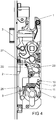
- FIG. 1 shows a lock with a lock case 1, with a latch 2 and a latch 3.
- the latch 3 is biased by a spring element 4 in the protruding position shown and can be moved by a follower 5 or by a locking device 6 in a retracted position.
- the locking device 6 is executed in a preferred embodiment of the invention, which is not explicitly shown here, in two parts and consists of a lower and upper part, which are interconnected by a guide having a clearance. Thus, both parts of the locking device 6 can be moved within specified limits independently.
- the lock is equipped with a drive rod 7, which has a positive connection with the lower part of the locking device 6.
- the drive rod 7 is used, for example, to drive sub-locking elements, not shown, and is held by a button 50 in the unlocked position until it is actuated when closing the door, whereby the drive rod 7 is released and together with the lower part of the locking device 6 by gravity the locking position can fall without the upper part of the locking device 6 and an associated gear 22 to move.
- the bolt 2 and the drive rod 7 can be driven by the locking device 6 by means of a lock cylinder inserted in a receptacle 8 of the lock.
- a lock cylinder inserted in a receptacle 8 of the lock.
- only one driver 9 is shown by the lock cylinder, in the region of movement of which two segments 10, 11 protrude.
- the segments 10, 11 are designed arcuate and extend over different sized circular arcs.
- the segments 10 guide pins 12 and guide grooves 13, 14, with which they are guided against each other and against side walls 15 of the lock case 1.
- only the behind the segments 10, 11 arranged side wall 15 is shown.
- One of the segments 10 has a lever arm 16 with a pin 17 which is concealed here.
- the pin 17 penetrates into a slotted guide 18 of a bolt tail 19 of the bolt 2.
- the second segment 11 has an in FIG. 8 illustrated toothing 20, with which there is a in FIG. 2 illustrated pinion 21 of a transmission 22 drives.
- the toothing 20 is formed as a partial toothed ring.
- the pinion 21 of the transmission 22 drives a small diameter gear 24 and a rack 25 on a slide 26 via a large diameter gear 23.
- the slider 26 is connected to a shoulder 27 a control pin 28 of a pivotable unlocking element 29 opposite.
- the unlocking element 29 has a second, here concealed pin 30, which penetrates into a further slotted guide 31 of the bolt tail 19.
- the lock has a locking device 32 for blocking the locking device 6.
- the locking device 32 has a pivotally mounted locking element 33 which faces a pivotally mounted unlocking element 34 as well.
- the unlocking element 34 is opposite to a gear 35 driven by the cam 35.
- the blocking element 33 has a control pin 34, which projects into the plane of the unlocking element 34. In the illustrated position, the blocking element 33 rests with a supporting edge 37 on a side edge 38 of the locking tail 19.
- the force for supporting the blocking element 33 on the side edge 38 can be generated by gravity or a spring element, not shown.
- FIG. 1 shows the lock in an unlocked position in which the case 3 can be withdrawn via an operation of the follower 5 in the lock case 1. If you drive the lock out of the in FIG. 1 shown position on the driver 9 counterclockwise, you get to the in FIG. 2 illustrated locking position.
- the lever arm 16 having segment 10 is pivoted along the guide grooves 14 and displaced a pin 17 in the slotted guide 18 in the bar tail 19. In this case, the bolt 2 is extended from the lock case 1.
- the blocking element 33 slides on the side edge 38 of the
- Bolt tail 19 along and falls by gravity or a spring force, not shown, with a support edge 39 behind a trailing edge 40 of the bolt tail.
- the latch 2 can not be pressed by hand into the lock case 1 inside. Opposite the position in FIG. 1 is connected to the transmission 22 second segment 11 is not moved.
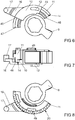
- FIG. 6 shows enlarged the segments 10, 11 and the cam 9 of the castle.
- the driver 9 is part of a lock cylinder, not shown, inserted in the receptacle 8 of the lock.
- the segments 10, 11 each have stop shoulders 44-47, with which they protrude into the range of movement of the driver 9.
- FIG. 7 shows the segments 10, 11 in a side view and FIG. 8 in a view from below.
- FIG. 7 shows that one of the segments 10 has a guide pin 48, which in the already in the FIGS. 1 and 6 shown guide groove 14 of the other segment 11 penetrates.
- FIG. 8 is the arranged on the second segment 11 teeth 20 to drive the transmission 22 can be seen.
- the segments 10, 11 each have technological guide pins 12, 49, with which they penetrate into the guide grooves 13 of the side walls 15 of the lock case 1.
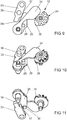
- FIG. 9 shows the locking device 32 of the lock with the blocking element 33 and the Entsperrelement 34 and the unlocking 29. Furthermore, the drivable by the gear 22 cam 35 for deflecting the Entsperrides 34 is shown.
- FIGS. 10 and 11 show the locking device 32 in different perspective views. It can be seen here that the blocking element 33, the unlocking element 34 and the unlocking element 29 are arranged in different planes. The unlocking element 34 is arranged in the plane of the cam 35. The control pin 36 of the blocking element 33 projects into the plane of the unlocking element 34.
Landscapes
- Engineering & Computer Science (AREA)
- Mechanical Engineering (AREA)
- Lock And Its Accessories (AREA)
Abstract
Description
- Die Erfindung betrifft ein Schloss mit einer einen Riegel aufweisenden Riegeleinrichtung zum wahlweisen Antrieb des Schlosses in eine Verriegelungsstellung oder Entriegelungsstellung, mit einer Aufnahme für einen Schließzylinder, mit einem beweglich geführten Segment, welches in den Bewegungsbereich eines Mitnehmers eines in der Aufnahme angeordneten Schließzylinders hineinragt, wobei das Segment zur Ansteuerung der Riegeleinrichtung ausgebildet ist.
- Ein solches Schloss ist beispielsweise aus der
EP 2 674 555 A2 bekannt. Bei diesem Schloss sind ein vorschließendes Bogenstück und ein rückschließendes Bogenstück in der Aufnahme für den Schließzylinder angeordnet. Durch Antrieb des Mitnehmers über den Schließzylinder treiben die Bogenstücke einen Schieber zur Verriegelung des Schlosses in die eine oder andere Richtung an. Dem Mitnehmer gegenüberstehende Schultern der Bogenstücke sind derart bemessen, dass der Schieber ohne Verdrehen der Bogenstücke zwischen seiner Sperrstellung und seiner Freigabestellung verlagerbar ist. Nachteilig bei diesem Schloss ist, dass es sehr leicht durch Antrieb des Schiebers manipulierbar ist. - Aus der
EP 2 615 229 A2 ist eine Schließanlage bekannt bei der eine Schlossnuss über eine Schlosskette auf einen Zentralriegel einwirkt. Eine Riegelsperre ist mit dem Schließzylinder verbunden. Die Riegelsperre ist aus einer die Schlosskette freigebenden Stellung in eine die Schlosskette blockierende Stellung bewegbar. Damit gestaltet sich die Ansteuerung der Schließanlage über die Schlossnuss und den Schließzylinder sehr aufwändig. - Ein Schloss ist beispielsweise aus der
DE 10 2006 059 568 B4 mit einem Hauptschloss und mehreren Nebenschlössern bekannt. Bei diesem Schloss umschließt ein C-förmiges Bauteil die Aufnahme für den Schließzylinder. Das C-förmige Bauteil wird beim Antrieb des in der Aufnahme angeordneten Schließzylinders verdreht. Auf der Außenseite des C-förmigen Bauteils ist eine Verzahnung angeordnet, welche die Riegeleinrichtung antreibt. Die Riegeleinrichtung treibt anschließend den Riegel und einen Schieber zum Antrieb der Nebenschlösser an. - Der Erfindung liegt das Problem zugrunde, ein Schloss der eingangs genannten Art so weiter zu bilden, dass es einen möglichst hohen Schutz gegen ein unberechtigtes Entriegeln bietet.
- Dieses Problem wird erfindungsgemäß dadurch gelöst, dass die Riegeleinrichtung eine Sperreinrichtung aufweist und dass die Riegeleinrichtung in der Verriegelungsstellung von der Sperreinrichtung blockiert ist und dass zur Entriegelung in zeitlicher Abfolge zunächst die Sperreinrichtung in eine die Riegeleinrichtung freigebende Stellung und anschließend die Riegeleinrichtung in die Entriegelungsstellung durch Antrieb des Schließzylinders ansteuerbar ist.
- Durch diese Gestaltung hat das Schloss eine Sperreinrichtung, mit der die Riegeleinrichtung blockiert werden kann. Daher ist es für den Antrieb der Riegeleinrichtung zunächst erforderlich die Sperreinrichtung anzusteuern.
Eine Entsperrung erfolgt erst durch Betätigung des Schließzylinders und der damit verbundenen Ansteuerung der Sperreinrichtung. Damit kann die Riegeleinrichtung nicht manuell ohne Betätigung des Schließzylinders angesteuert werden. Das Schloss bietet hierdurch einen hohen Schutz gegen ein unberechtigtes Entriegeln. Die zeitliche Abfolge der Ansteuerung der Sperreinrichtung und der Riegeleinrichtung kann durch einen Totgang im Antrieb der Riegeleinrichtung erzeugt sein. - Die Ansteuerung der Sperreinrichtung gestaltet sich gemäß einer anderen vorteilhaften Weiterbildung der Erfindung besonders einfach, wenn ein zweites Segment in den Bewegungsbereich des Mitnehmers des in der Aufnahme montierten Schließzylinders hineinragt und dass das zweite Segment mit der Sperreinrichtung zur Blockierung oder Freigabe der Riegeleinrichtung gekoppelt ist.
- Der bauliche Aufwand der Sperreinrichtung lässt sich gemäß einer anderen vorteilhaften Weiterbildung der Erfindung besonders gering halten, wenn die Sperreinrichtung ein Sperrelement hat und wenn das Sperrelement von einer Kraft in eine die Riegeleinrichtung blockierende Stellung ausgelenkt und beim Antrieb durch das zweite Segment in die Freigabestellung bewegbar ist. Das Sperrelement kann von der Schwerkraft oder von der Kraft eines Federelementes ausgelenkt sein.
- Die Sperreinrichtung gestaltet sich gemäß einer anderen vorteilhaften Weiterbildung der Erfindung konstruktiv besonders einfach, wenn die Sperreinrichtung ein dem Sperrelement gegenüberstehendes Entsperrelement hat und wenn beim Antrieb des Entsperrelementes das Sperrelement gegen die auslenkende Kraft in die die Riegeleinrichtung freigebende Stellung antreibbar ist. Zum Antrieb des Entsperrelementes kann das Getriebe beispielsweise einen Nocken haben, welcher bei der Bewegung des zweiten Segments das Entsperrelement auslenkt.
- Die Koppelung des Sperrelementes mit der Bewegung des Entsperrelementes gestaltet sich gemäß einer anderen vorteilhaften Weiterbildung der Erfindung besonders einfach, wenn das Sperrelement einen in den Bewegungsbereich des Entsperrelementes hineinragenden Steuerzapfen hat.
- Die Sperreinrichtung gestaltet sich gemäß einer anderen vorteilhaften Weiterbildung der Erfindung konstruktiv besonders einfach, wenn das Sperrelement in der die Riegeleinrichtung blockierenden Stellung eine Hinterkante des Riegels mit einer Sperrkante hintergreift. Vorzugsweise sind die Stützkante und eine Lagerung des Sperrelementes parallel zur Bewegungsrichtung des Riegels angeordnet.
- Fehlstellungen des Sperrelementes bei der berechtigten Betätigung der Riegeleinrichtung lassen sich gemäß einer anderen vorteilhaften Weiterbildung der Erfindung einfach vermeiden, wenn das Sperrelement in der die Riegeleinrichtung freigebenden Stellung mit einer Stützkante auf einer Seitenkante des Riegels aufliegt.
- Die Ansteuerung des Entsperrelementes gestaltet sich gemäß einer anderen vorteilhaften Weiterbildung der Erfindung konstruktiv besonders einfach, wenn das zweite Segment zum Antrieb eines das Entsperrelement auslenkenden Nockens ausgebildet ist.
- Das Schloss ermöglicht die Ansteuerung einer Vielzahl von verschiedenen Bauteilen, wenn eines der Segmente zum Antrieb des Riegels und das andere der Segmente zum Antrieb eines Schiebers ausgebildet ist. Damit lässt sich der Riegel beispielsweise unabhängig von dem Schieber in die Verriegelungsstellung antreiben. Über einen solchen Schieber kann auch eine Drückernuss angetrieben werden, um eine Falle zurückzuziehen. Der Schieber kann beispielsweise eine Treibstange zur Ansteuerung von Nebenschlössern und damit einer weiteren Riegeleinrichtung ansteuern. Ebenso kann der Schieber eine Sperreinrichtung zur Blockierung des Riegels ansteuern.
- Der Riegel lässt sich gemäß einer anderen vorteilhaften Weiterbildung der Erfindung von dem einen Segment in die Verriegelungsstellung und von dem anderen Segment in die Entriegelungsstellung antreiben, wenn der Schieber zum Antrieb einem Entriegelungselement gegenübersteht und wenn das Entriegelungselement zum Antrieb des Riegels in die Entriegelungsstellung ausgebildet ist. Durch diese Gestaltung weist das Schloss einen hohen Schutz gegen ein unberechtigtes Entriegeln auf. Zum Antrieb kann das Entriegelungselement einen in eine Kulissenführung des Riegels eindringenden Zapfen aufweisen.
- Das Schloss gestaltet sich gemäß einer anderen vorteilhaften Weiterbildung der Erfindung konstruktiv besonders einfach, wenn zumindest eines der Segmente mit einem Hebelarm verbunden ist.
- Der bauliche Aufwand zum Antrieb des Riegels in die Verriegelungsstellung lässt sich gemäß einer anderen vorteilhaften Weiterbildung der Erfindung besonders gering halten, wenn der Hebelarm einen in eine Kulissenführung eindringenden Zapfen zur Ansteuerung des Riegels hat.
- Eine Ansteuerung einer Einrichtung mittels mehrerer Umdrehungen des Schließzylinders lässt sich gemäß einer anderen vorteilhaften Weiterbildung der Erfindung erreichen, wenn zumindest eines der Segmente mit einer Verzahnung verbunden ist und wenn die Verzahnung Teil eines Getriebes ist. Über das Getriebe lässt sich der Riegel in die Entriegelungsstellung bewegen und beispielsweise auch eine Treibstange zur Ansteuerung von Nebenschlössern antreiben.
- Eine zeitlich getrennte Ansteuerung der Bauteile der Riegeleinrichtung lässt sich gemäß einer anderen vorteilhaften Weiterbildung der Erfindung einfach erzeugen, wenn die Segmente in ihren in den Bewegungsbereich des Mitnehmers des Schließzylinders hineinragenden Abschnitten unterschiedliche Abmessungen aufweisen. Durch diese Gestaltung ist es möglich mit dem einen Segment die Sperreinrichtung für den Riegel anzusteuern und mit dem anderem Segment den Riegel selbst. Damit lässt sich zunächst die Sperreinrichtung lösen und anschließend der Riegel bewegen.
- Der Ablauf des Schließmechanismus lässt sich gemäß einer anderen vorteilhaften Weiterbildung der Erfindung dadurch verbessern, dass die Riegeleinrichtung zweiteilig ausgeführt ist und eine Schließreihenfolge dadurch festgelegt ist, dass die Treibstange mit einem unteren Teil der Riegeleinrichtung verbunden ist und von einem Taster gehalten werden kann, welcher beim Schließen der Tür den unteren Teil der Riegeleinrichtung freigibt, welcher einen Freigang zum oberen Teil der Riegeleinrichtung aufweist. Bei Betätigung des Tasters wird die Treibstange freigegeben, sodass diese zusammen mit dem unteren Teil der Riegeleinrichtung durch die Schwerkraft hinabfallen kann und zum Beispiel vorhandene Nebenverriegelungselemente in die Verriegelungsstellung verlagert. Durch den Freigang zwischen den beiden Teilen der Riegeleinrichtung ist dieser anfängliche Mechanismus von einem Getriebe des Schlosses entkoppelt, sodass dieses während des ersten Verriegelungsschrittes nicht mitgeschleppt wird und der Mechanismus somit besonders verschleißarm und leichtgängig ausgeführt ist. Sobald der obere Teil der Riegeleinrichtung durch Betätigung des Getriebes in Entriegelungsrichtung verlagert wird, nimmt dieser den unteren Teil entgegen des Freigangs mit.
Die Erfindung lässt zahlreiche Ausführungsformen zu. Zur weiteren Verdeutlichung ihres Grundprinzips ist eine davon in der Zeichnung dargestellt und wird nachfolgend beschrieben. Diese zeigt in - Fig. 1
- ein Schloss in einer Grundstellung,
- Fig. 2 - 5
- das Schloss aus
Figur 1 in verschiedenen Stellungen, - Fig. 6
- eine vergrößerte Darstellung zweier Segmente des Schlosses aus
Figur 1 , - Fig. 7
- eine Seitenansicht der Segmente aus
Figur 7 , - Fig. 8
- eine Ansicht von unten auf die Segmente aus
Figur 7 , - Fig. 9
- vergrößert Bauteile einer Sperreinrichtung und ein Entriegelungselement des Schlosses aus
Figur 1 , - Fig. 10
- die Sperreinrichtung aus
Figur 9 in einer perspektivischen Darstellung, - Fig. 11
- die Sperreinrichtung aus
Figur 9 in einer weiteren perspektivischen Darstellung. -
Figur 1 zeigt ein Schloss mit einem Schlosskasten 1, mit einem Riegel 2 und einer Falle 3. Die Falle 3 ist von einem Federelement 4 in die dargestellte hervorstehende Stellung vorgespannt und lässt sich von einer Drückernuss 5 oder von einer Riegeleinrichtung 6 in eine zurückgezogene Stellung bewegen. Die Riegeleinrichtung 6 ist in einer bevorzugten Ausführungsform der Erfindung, was hier nicht explizit gezeigt ist, zweiteilig ausgeführt und besteht aus einem unteren und oberen Teil, welche durch eine einen Freigang aufweisende Führung miteinander verbunden sind. Somit lassen sich beide Teile der Riegeleinrichtung 6 in festgelegten Grenzen unabhängig voneinander bewegen. Weiterhin ist das Schloss mit einer Treibstange 7 ausgestattet, welche eine formschlüssige Verbindung mit dem unteren Teil der Riegeleinrichtung 6 aufweist. Die Treibstange 7 dient beispielsweise zum Antrieb von nicht dargestellten Nebenverriegelungselementen und wird von einem Taster 50 in der entriegelten Stellung gehalten bis dieser beim Schließen des Türflügels betätigt wird, wodurch die Treibstange 7 freigegeben wird und zusammen mit dem unteren Teil der Riegeleinrichtung 6 durch die Schwerkraft in die Verriegelungsstellung fallen kann ohne den oberen Teil der Riegeleinrichtung 6 und ein damit verbundenes Getriebe 22 zu bewegen. - Der Riegel 2 und die Treibstange 7 lassen sich von der Riegeleinrichtung 6 mittels eines in einer Aufnahme 8 des Schlosses eingesetzten Schließzylinders antreiben. Zur Vereinfachung der Zeichnung ist von dem Schließzylinder nur ein Mitnehmer 9 dargestellt, in dessen Bewegungsbereich zwei Segmente 10, 11 hineinragen. Die Segmente 10, 11 sind bogenförmig gestaltet und erstrecken sich über unterschiedlich große Kreisbögen. Weiterhin haben die Segmente 10 Führungszapfen 12 und Führungsnuten 13, 14, mit denen sie aneinander und gegenüber Seitenwänden 15 des Schlosskastens 1 geführt sind. Zur Vereinfachung der Zeichnung ist nur die hinter den Segmenten 10, 11 angeordnete Seitenwand 15 dargestellt.
- Eines der Segmente 10 hat einen Hebelarm 16 mit einem hier verdeckten Zapfen 17. Der Zapfen 17 dringt in eine Kulissenführung 18 eines Riegelschwanzes 19 des Riegels 2 ein. Durch eine Auslenkung des Hebelarms 16 bei einem Antrieb des mit diesem verbundenen Segmentes 10 wird der Riegel 2 in eine Entriegelungsstellung bewegt. Das zweite Segment 11 hat eine in
Figur 8 dargestellte Verzahnung 20, mit dem es ein inFigur 2 dargestelltes Ritzel 21 eines Getriebes 22 antreibt. Die Verzahnung 20 ist als Teilzahnkranz ausgebildet. Das Ritzel 21 des Getriebes 22 treibt über ein durchmessergroßes Zahnrad 23 ein durchmesserkleines Zahnrad 24 und eine Zahnstange 25 auf einen Schieber 26 an. Der Schieber 26 steht mit einer Schulter 27 einem Steuerzapfen 28 eines schwenkbaren Entriegelungselementes 29 gegenüber. Das Entriegelungselement 29 hat einen zweiten, hier verdeckt angeordneten Zapfen 30, der in eine weitere Kulissenführung 31 des Riegelschwanzes 19 eindringt. Durch einen Antrieb des Entriegelungselementes 29 über das Getriebe 22 und den Schieber 26 lässt sich der Riegel 2 in die dargestellte, im Schlosskasten 1 befindliche Entriegelungsstellung zurückziehen. Der Schieber 26 ist zudem mit der Treibstange 7 gekoppelt. - Weiterhin hat das Schloss eine Sperreinrichtung 32 zur Blockierung der Riegeleinrichtung 6. Die Sperreinrichtung 32 hat ein schwenkbar gelagertes Sperrelement 33, welches einem ebenfalls schwenkbar gelagerten Entsperrelement 34 gegenübersteht. Das Entsperrelement 34 steht einem von dem Getriebe 22 angetriebenen Nocken 35 gegenüber. Das Sperrelement 33 hat einen Steuerzapfen 34, welcher in die Ebene des Entsperrelementes 34 hineinragt. In der dargestellten Stellung liegt das Sperrelement 33 mit einer Stützkante 37 auf einer Seitenkante 38 des Riegelschwanzes 19 auf. Die Kraft zur Auflage des Sperrelementes 33 auf der Seitenkante 38 kann von der Schwerkraft oder einem nicht dargestellten Federelement erzeugt werden.
-
Figur 1 zeigt das Schloss in einer Entriegelungsstellung, in der die Falle 3 über eine Betätigung der Drückernuss 5 in den Schlosskasten 1 zurückgezogen werden kann. Treibt man das Schloss ausgehend aus der inFigur 1 dargestellten Stellung über den Mitnehmer 9 gegen den Uhrzeigersinn an, gelangt man in die inFigur 2 dargestellte Verriegelungsstellung. Beim Antrieb wird das den Hebelarm 16 aufweisende Segment 10 entlang der Führungsnuten 14 verschwenkt und der eine Zapfen 17 in der Kulissenführung 18 im Riegelschwanz 19 verschoben. Dabei wird der Riegel 2 aus dem Schlosskasten 1 ausgefahren. Das Sperrelement 33 gleitet dabei an der Seitenkante 38 des - Riegelschwanzes 19 entlang und fällt durch die Schwerkraft oder einer nicht dargestellten Federkraft mit einer Stützkante 39 hinter eine Hinterkante 40 des Riegelschwanzes. Damit kann der Riegel 2 nicht mehr von Hand in den Schlosskasten 1 hinein gedrückt werden. Gegenüber der Stellung in
Figur 1 ist das mit dem Getriebe 22 verbundene zweite Segment 11 nicht bewegt. - Zur Entriegelung wird der Mitnehmer 9 im Uhrzeigersinn verschwenkt, bis er das zweite Segment 11 verschiebt. Diese Stellung ist in
Figur 3 dargestellt. Dabei wird zunächst das Getriebe 22 von dem zweiten Segment 11 angetrieben. Das Getriebe 22 verschiebt durch den Antrieb der Zahnstange 25 den Schieber 26. Gleichzeitig verschwenkt das Getriebe 22 den Nocken 35, welcher das Entsperrelement 34 auslenkt und das Sperrelement 33 aus dem Bewegungsbereich des Riegelschwanzes 19 entfernt. Da das den Hebelarm 16 aufweisende Segment 10 kürzer ist als das zweite Segment 11, verbleibt dieses zunächst in seiner Lage. - Treibt man ausgehend von der Stellung aus
Figur 3 den Mitnehmer 9 weiter im Uhrzeigersinn an, lässt sich nun der Riegel 2 durch den Antrieb der Schulter 27 des Schiebers 26 gegen den Steuerzapfen 28 des Entriegelungselementes 29 zurückziehen. Der von der Schulter 27 angetriebene Steuerzapfen 28 des Entriegelungselementes 29 verlagert das Entriegelungselement 29 derart, dass der zweite Zapfen 30 den Riegelschwanz 19 über die zweite Kulissenführung 31 zurückzieht. Diese Stellung ist inFigur 4 dargestellt. - Der in
Figur 2 dargestellte Abstand des Steuerzapfens 28 von der Schulter 27 ermöglicht damit einen Totgang beim Antrieb des Schiebers 26, so dass in zeitlicher Abfolge zunächst die Sperreinrichtung 32 in die die Riegeleinrichtung 6 freigebende Stellung und anschließend die Riegeleinrichtung 6 in die Entriegelungsstellung angetrieben wird. - Durch den weiteren Antrieb des Schiebers 26 wird anschließend die Falle 3 in den Schlosskasten 1 zurückgezogen und die Treibstange 7 verschoben. Ein mit der Treibstange 7 verbundenes Stellelement 41 hat hierzu einen Fallenrückzugszapfen 42, welcher einen Fallenrückzugshebel 43 verschwenkt und damit die Falle 3 zurückzieht. Diese Stellung ist in
Figur 5 dargestellt. -
Figur 6 zeigt vergrößert die Segmente 10, 11 und den Mitnehmer 9 des Schlosses. Der Mitnehmer 9 ist Teil eines nicht dargestellten, in der Aufnahme 8 des Schlosses eingesetzten Schließzylinders. Die Segmente 10, 11 weisen jeweils Anschlagschultern 44-47 auf, mit welchen sie in den Bewegungsbereich des Mitnehmers 9 hineinragen.Figur 7 zeigt die Segmente 10, 11 in einer Seitenansicht undFigur 8 in einer Ansicht von unten.Figur 7 zeigt, dass eines der Segmente 10 einen Führungszapfen 48 hat, welcher in die bereits in denFiguren 1 und6 dargestellte Führungsnut 14 des anderen Segments 11 eindringt. InFigur 8 ist die an dem zweiten Segment 11 angeordnete Verzahnung 20 zum Antrieb des Getriebes 22 zu erkennen. Die Segmente 10, 11 weisen jeweils voneinander wegweisende Führungszapfen 12, 49 auf, mit welchen sie in die Führungsnuten 13 der Seitenwandungen 15 des Schlosskastens 1 eindringen. -
Figur 9 zeigt die Sperreinrichtung 32 des Schlosses mit dem Sperrelement 33 und dem Entsperrelement 34 und das Entriegelungselement 29. Weiterhin ist der von dem Getriebe 22 antreibbare Nocken 35 zur Auslenkung des Entsperrelementes 34 dargestellt. DieFiguren 10 und 11 zeigen die Sperreinrichtung 32 in unterschiedlichen perspektivischen Ansichten. Hierbei ist zu erkennen, dass das Sperrelement 33, das Entsperrelement 34 und das Entriegelungselement 29 in unterschiedlichen Ebenen angeordnet sind. Das Entsperrelement 34 ist in der Ebene des Nockens 35 angeordnet. Der Steuerzapfen 36 des Sperrelementes 33 ragt in die Ebene des Entsperrelementes 34 hinein.
Claims (15)
- Schloss mit einer einen Riegel (2) aufweisenden Riegeleinrichtung (6) zum wahlweisen Antrieb des Schlosses in eine Verriegelungsstellung oder Entriegelungsstellung, mit einer Aufnahme (8) für einen Schließzylinder, mit einem beweglich geführten Segment (10), welches in den Bewegungsbereich eines Mitnehmers (9) eines in der Aufnahme angeordneten Schließzylinders (8) hineinragt, wobei das Segment (10) zur Ansteuerung der Riegeleinrichtung (6) ausgebildet ist, dadurch gekennzeichnet, dass die Riegeleinrichtung (6) eine Sperreinrichtung (32) aufweist und dass die Riegeleinrichtung (6) in der Verriegelungsstellung von der Sperreinrichtung (32) blockiert ist und dass zur Entriegelung in zeitlicher Abfolge zunächst die Sperreinrichtung (32) in eine die Riegeleinrichtung (6) freigebende Stellung und anschließend die Riegeleinrichtung (6) in die Entriegelungsstellung durch Antrieb des Schließzylinders ansteuerbar ist.
- Schloss nach Anspruch 1, dadurch gekennzeichnet, dass ein zweites Segment (11) in den Bewegungsbereich des Mitnehmers (9) des in der Aufnahme montierten Schließzylinders (8) hineinragt und dass das zweite Segment (11) mit der Sperreinrichtung (32) zur Blockierung oder Freigabe der Riegeleinrichtung (6) gekoppelt ist.
- Schloss nach Anspruch 2, dadurch gekennzeichnet, dass die Sperreinrichtung (32) ein Sperrelement (33) hat und dass das Sperrelement (33) von einer Kraft in eine die Riegeleinrichtung (6) blockierende Stellung ausgelenkt und beim Antrieb durch das zweite Segment (11) in die Freigabestellung bewegbar ist.
- Schloss nach Anspruch 3, dadurch gekennzeichnet, dass die Sperreinrichtung (32) ein dem Sperrelement (33) gegenüberstehendes Entsperrelement (34) hat und dass beim Antrieb des Entsperrelementes (34) das Sperrelement (33) gegen die auslenkende Kraft in die die Riegeleinrichtung (6) freigebende Stellung antreibbar ist.
- Schloss nach Anspruch 3 oder 4, dadurch gekennzeichnet, dass das Sperrelement (33) einen in den Bewegungsbereich des Entsperrelementes (34) hineinragenden Steuerzapfen (36) hat.
- Schloss nach einem der Ansprüche 3 bis 5, dadurch gekennzeichnet, dass das Sperrelement (33) in der die Riegeleinrichtung (6) blockierenden Stellung eine Hinterkante (40) des Riegels (2) mit einer Sperrkante (39) hintergreift.
- Schloss nach einem der Ansprüche 2 bis 6, dadurch gekennzeichnet, dass das Sperrelement (33) in der die Riegeleinrichtung (6) freigebenden Stellung mit einer Stützkante (37) auf einer Seitenkante (38) des Riegels (2) aufliegt.
- Schloss nach einem der Ansprüche 4 bis 7, dadurch gekennzeichnet, dass das zweite Segment (11) zum Antrieb eines das Entsperrelement (34) auslenkenden Nockens (35) ausgebildet ist.
- Schloss nach einem der Ansprüche 2 bis 8, dadurch gekennzeichnet, dass eines der Segmente (10) zum Antrieb des Riegels (2) und das andere der Segmente (11) zum Antrieb eines Schiebers (26) ausgebildet ist.
- Schloss nach Anspruch 9, dadurch gekennzeichnet, dass der Schieber (26) zum Antrieb einem Entriegelungselement (29) gegenübersteht und dass das Entriegelungselement (29) zum Antrieb des Riegels (2) in die Entriegelungsstellung ausgebildet ist.
- Schloss nach zumindest einem der Ansprüche 2 bis 10, dadurch gekennzeichnet, dass zumindest eines der Segmente (10) mit einem Hebelarm (16) verbunden ist.
- Schloss nach Anspruch 11, dadurch gekennzeichnet, dass der Hebelarm (16) einen in eine Kulissenführung (18) eindringenden Zapfen (17) zur Ansteuerung des Riegels (2) hat.
- Schloss nach zumindest einem der Ansprüche 2 bis 12, dadurch gekennzeichnet, dass zumindest eines der Segmente (11) mit einer Verzahnung (20) verbunden ist und dass die Verzahnung (20) Teil eines Getriebes (22) ist.
- Schloss nach zumindest einem der Ansprüche 2 bis 13, dadurch gekennzeichnet, dass die Segmente (10, 11) in ihren in den Bewegungsbereich des Mitnehmers (9) des Schließzylinders (8) hineinragenden Abschnitten unterschiedliche Abmessungen aufweisen.
- Schloss nach zumindest einem der vorhergehenden Ansprüche, dadurch gekennzeichnet, dass die Riegeleinrichtung (6) zweiteilig ausgeführt ist und eine Schließreihenfolge dadurch festgelegt ist, dass die Treibstange (7) mit einem unteren Teil der Riegeleinrichtung (6) verbunden ist und von einem Taster (50) gehalten werden kann, welcher beim Schließen der Tür den unteren Teil der Riegeleinrichtung (6) freigibt, welcher einen Freigang zum oberen Teil der Riegeleinrichtung (6) aufweist.
Priority Applications (1)
| Application Number | Priority Date | Filing Date | Title |
|---|---|---|---|
| PL18209288T PL3498943T3 (pl) | 2017-12-13 | 2018-11-29 | Zamek |
Applications Claiming Priority (1)
| Application Number | Priority Date | Filing Date | Title |
|---|---|---|---|
| DE102017222661.7A DE102017222661A1 (de) | 2017-12-13 | 2017-12-13 | Schloss |
Publications (2)
| Publication Number | Publication Date |
|---|---|
| EP3498943A1 true EP3498943A1 (de) | 2019-06-19 |
| EP3498943B1 EP3498943B1 (de) | 2021-06-09 |
Family
ID=64559608
Family Applications (1)
| Application Number | Title | Priority Date | Filing Date |
|---|---|---|---|
| EP18209288.2A Active EP3498943B1 (de) | 2017-12-13 | 2018-11-29 | Schloss |
Country Status (3)
| Country | Link |
|---|---|
| EP (1) | EP3498943B1 (de) |
| DE (1) | DE102017222661A1 (de) |
| PL (1) | PL3498943T3 (de) |
Citations (7)
| Publication number | Priority date | Publication date | Assignee | Title |
|---|---|---|---|---|
| GB2268221A (en) * | 1992-06-26 | 1994-01-05 | Parkes Josiah & Sons Ltd | Multi-point lock |
| EP1199427A1 (de) * | 2000-10-20 | 2002-04-24 | Stremler | Schloss mit verschiebbarem Riegel und verbesserter Sicherheit |
| DE10202088A1 (de) * | 2001-01-19 | 2002-07-25 | Msl Schloss Und Beschlaegefabr | Schloss |
| DE102006059568B4 (de) | 2006-12-16 | 2009-07-30 | Carl Fuhr Gmbh & Co. Kg | Schließanlage für Türen, Fenster oder dergleichen, insbesondere Treibstangenschloss mit Panikfunktion und Mehrpunktverriegelung |
| DE202013000921U1 (de) * | 2013-01-30 | 2013-02-20 | Kfv Karl Fliether Gmbh & Co. Kg | Panikschloss |
| EP2615229A2 (de) | 2012-01-13 | 2013-07-17 | Carl Fuhr GmbH & Co. KG | Schließanlage |
| EP2674555A2 (de) | 2005-07-14 | 2013-12-18 | KFV Karl Fliether GmbH & Co. KG | Fluchttürschloss |
-
2017
- 2017-12-13 DE DE102017222661.7A patent/DE102017222661A1/de not_active Withdrawn
-
2018
- 2018-11-29 EP EP18209288.2A patent/EP3498943B1/de active Active
- 2018-11-29 PL PL18209288T patent/PL3498943T3/pl unknown
Patent Citations (7)
| Publication number | Priority date | Publication date | Assignee | Title |
|---|---|---|---|---|
| GB2268221A (en) * | 1992-06-26 | 1994-01-05 | Parkes Josiah & Sons Ltd | Multi-point lock |
| EP1199427A1 (de) * | 2000-10-20 | 2002-04-24 | Stremler | Schloss mit verschiebbarem Riegel und verbesserter Sicherheit |
| DE10202088A1 (de) * | 2001-01-19 | 2002-07-25 | Msl Schloss Und Beschlaegefabr | Schloss |
| EP2674555A2 (de) | 2005-07-14 | 2013-12-18 | KFV Karl Fliether GmbH & Co. KG | Fluchttürschloss |
| DE102006059568B4 (de) | 2006-12-16 | 2009-07-30 | Carl Fuhr Gmbh & Co. Kg | Schließanlage für Türen, Fenster oder dergleichen, insbesondere Treibstangenschloss mit Panikfunktion und Mehrpunktverriegelung |
| EP2615229A2 (de) | 2012-01-13 | 2013-07-17 | Carl Fuhr GmbH & Co. KG | Schließanlage |
| DE202013000921U1 (de) * | 2013-01-30 | 2013-02-20 | Kfv Karl Fliether Gmbh & Co. Kg | Panikschloss |
Also Published As
| Publication number | Publication date |
|---|---|
| EP3498943B1 (de) | 2021-06-09 |
| DE102017222661A1 (de) | 2019-06-13 |
| PL3498943T3 (pl) | 2021-11-29 |
Similar Documents
| Publication | Publication Date | Title |
|---|---|---|
| EP2951368B1 (de) | Panikschloss | |
| DE2433322B2 (de) | Panik-Hauptschloß mit Fallen-Nebenverschlüssen | |
| EP2706175B1 (de) | Mehrfachverriegelungsschloss | |
| EP3498942A1 (de) | Schloss | |
| EP3498943B1 (de) | Schloss | |
| EP3091151A1 (de) | Treibstangensperre für einen treibstangenbeschlag | |
| EP3018274B1 (de) | Gegenschloss eines treibstangenschlosses einer zweiflügeligen tür | |
| EP3018273B1 (de) | Zusatzverriegelung | |
| EP2634330A2 (de) | Automatikschloss | |
| EP2634333A2 (de) | Schloss | |
| EP2738324B1 (de) | Schloss mit einer freigebbaren Dreheinheit | |
| EP2085543B1 (de) | Schloss | |
| EP4163462B1 (de) | Schloss mit einem schlosskasten und einem dem schlosskasten gegenüberstehend anzuordnenden schliessblech | |
| EP3215696A1 (de) | Schloss | |
| EP1024240B1 (de) | Verriegelungsvorrichtung | |
| EP2634331B1 (de) | Automatikschloss | |
| DE202012100133U1 (de) | Schließanlage | |
| DE69502206T3 (de) | Verriegelbares, mechanisches Schloss | |
| EP1514986A2 (de) | Treibstangenschloss | |
| DE2605763B2 (de) | Treibstangenschloß mit Falle | |
| EP3521538B1 (de) | Schloss mit einem fallenriegel | |
| DE19628010A1 (de) | Vorrichtung zur Verstellung der Schubstange einer Riegelwerks | |
| EP2998494B1 (de) | Treibstangenschloss | |
| EP4166739A1 (de) | Schloss mit einem schlosskasten | |
| AT516516B1 (de) | Schloss |
Legal Events
| Date | Code | Title | Description |
|---|---|---|---|
| PUAI | Public reference made under article 153(3) epc to a published international application that has entered the european phase |
Free format text: ORIGINAL CODE: 0009012 |
|
| STAA | Information on the status of an ep patent application or granted ep patent |
Free format text: STATUS: THE APPLICATION HAS BEEN PUBLISHED |
|
| AK | Designated contracting states |
Kind code of ref document: A1 Designated state(s): AL AT BE BG CH CY CZ DE DK EE ES FI FR GB GR HR HU IE IS IT LI LT LU LV MC MK MT NL NO PL PT RO RS SE SI SK SM TR |
|
| AX | Request for extension of the european patent |
Extension state: BA ME |
|
| STAA | Information on the status of an ep patent application or granted ep patent |
Free format text: STATUS: REQUEST FOR EXAMINATION WAS MADE |
|
| 17P | Request for examination filed |
Effective date: 20191120 |
|
| RBV | Designated contracting states (corrected) |
Designated state(s): AL AT BE BG CH CY CZ DE DK EE ES FI FR GB GR HR HU IE IS IT LI LT LU LV MC MK MT NL NO PL PT RO RS SE SI SK SM TR |
|
| GRAP | Despatch of communication of intention to grant a patent |
Free format text: ORIGINAL CODE: EPIDOSNIGR1 |
|
| STAA | Information on the status of an ep patent application or granted ep patent |
Free format text: STATUS: GRANT OF PATENT IS INTENDED |
|
| RIC1 | Information provided on ipc code assigned before grant |
Ipc: E05B 63/20 20060101ALN20201222BHEP Ipc: E05B 59/00 20060101ALI20201222BHEP Ipc: E05B 17/20 20060101AFI20201222BHEP Ipc: E05C 9/02 20060101ALI20201222BHEP |
|
| INTG | Intention to grant announced |
Effective date: 20210126 |
|
| GRAS | Grant fee paid |
Free format text: ORIGINAL CODE: EPIDOSNIGR3 |
|
| GRAA | (expected) grant |
Free format text: ORIGINAL CODE: 0009210 |
|
| STAA | Information on the status of an ep patent application or granted ep patent |
Free format text: STATUS: THE PATENT HAS BEEN GRANTED |
|
| AK | Designated contracting states |
Kind code of ref document: B1 Designated state(s): AL AT BE BG CH CY CZ DE DK EE ES FI FR GB GR HR HU IE IS IT LI LT LU LV MC MK MT NL NO PL PT RO RS SE SI SK SM TR |
|
| REG | Reference to a national code |
Ref country code: GB Ref legal event code: FG4D Free format text: NOT ENGLISH |
|
| REG | Reference to a national code |
Ref country code: CH Ref legal event code: EP Ref country code: AT Ref legal event code: REF Ref document number: 1400642 Country of ref document: AT Kind code of ref document: T Effective date: 20210615 |
|
| REG | Reference to a national code |
Ref country code: DE Ref legal event code: R096 Ref document number: 502018005604 Country of ref document: DE |
|
| REG | Reference to a national code |
Ref country code: IE Ref legal event code: FG4D Free format text: LANGUAGE OF EP DOCUMENT: GERMAN |
|
| REG | Reference to a national code |
Ref country code: NL Ref legal event code: FP |
|
| REG | Reference to a national code |
Ref country code: SE Ref legal event code: TRGR |
|
| REG | Reference to a national code |
Ref country code: LT Ref legal event code: MG9D |
|
| PG25 | Lapsed in a contracting state [announced via postgrant information from national office to epo] |
Ref country code: BG Free format text: LAPSE BECAUSE OF FAILURE TO SUBMIT A TRANSLATION OF THE DESCRIPTION OR TO PAY THE FEE WITHIN THE PRESCRIBED TIME-LIMIT Effective date: 20210909 Ref country code: HR Free format text: LAPSE BECAUSE OF FAILURE TO SUBMIT A TRANSLATION OF THE DESCRIPTION OR TO PAY THE FEE WITHIN THE PRESCRIBED TIME-LIMIT Effective date: 20210609 Ref country code: LT Free format text: LAPSE BECAUSE OF FAILURE TO SUBMIT A TRANSLATION OF THE DESCRIPTION OR TO PAY THE FEE WITHIN THE PRESCRIBED TIME-LIMIT Effective date: 20210609 Ref country code: FI Free format text: LAPSE BECAUSE OF FAILURE TO SUBMIT A TRANSLATION OF THE DESCRIPTION OR TO PAY THE FEE WITHIN THE PRESCRIBED TIME-LIMIT Effective date: 20210609 |
|
| PG25 | Lapsed in a contracting state [announced via postgrant information from national office to epo] |
Ref country code: RS Free format text: LAPSE BECAUSE OF FAILURE TO SUBMIT A TRANSLATION OF THE DESCRIPTION OR TO PAY THE FEE WITHIN THE PRESCRIBED TIME-LIMIT Effective date: 20210609 Ref country code: LV Free format text: LAPSE BECAUSE OF FAILURE TO SUBMIT A TRANSLATION OF THE DESCRIPTION OR TO PAY THE FEE WITHIN THE PRESCRIBED TIME-LIMIT Effective date: 20210609 Ref country code: NO Free format text: LAPSE BECAUSE OF FAILURE TO SUBMIT A TRANSLATION OF THE DESCRIPTION OR TO PAY THE FEE WITHIN THE PRESCRIBED TIME-LIMIT Effective date: 20210909 Ref country code: GR Free format text: LAPSE BECAUSE OF FAILURE TO SUBMIT A TRANSLATION OF THE DESCRIPTION OR TO PAY THE FEE WITHIN THE PRESCRIBED TIME-LIMIT Effective date: 20210910 |
|
| PG25 | Lapsed in a contracting state [announced via postgrant information from national office to epo] |
Ref country code: EE Free format text: LAPSE BECAUSE OF FAILURE TO SUBMIT A TRANSLATION OF THE DESCRIPTION OR TO PAY THE FEE WITHIN THE PRESCRIBED TIME-LIMIT Effective date: 20210609 Ref country code: ES Free format text: LAPSE BECAUSE OF FAILURE TO SUBMIT A TRANSLATION OF THE DESCRIPTION OR TO PAY THE FEE WITHIN THE PRESCRIBED TIME-LIMIT Effective date: 20210609 Ref country code: SM Free format text: LAPSE BECAUSE OF FAILURE TO SUBMIT A TRANSLATION OF THE DESCRIPTION OR TO PAY THE FEE WITHIN THE PRESCRIBED TIME-LIMIT Effective date: 20210609 Ref country code: SK Free format text: LAPSE BECAUSE OF FAILURE TO SUBMIT A TRANSLATION OF THE DESCRIPTION OR TO PAY THE FEE WITHIN THE PRESCRIBED TIME-LIMIT Effective date: 20210609 Ref country code: PT Free format text: LAPSE BECAUSE OF FAILURE TO SUBMIT A TRANSLATION OF THE DESCRIPTION OR TO PAY THE FEE WITHIN THE PRESCRIBED TIME-LIMIT Effective date: 20211011 Ref country code: RO Free format text: LAPSE BECAUSE OF FAILURE TO SUBMIT A TRANSLATION OF THE DESCRIPTION OR TO PAY THE FEE WITHIN THE PRESCRIBED TIME-LIMIT Effective date: 20210609 Ref country code: CZ Free format text: LAPSE BECAUSE OF FAILURE TO SUBMIT A TRANSLATION OF THE DESCRIPTION OR TO PAY THE FEE WITHIN THE PRESCRIBED TIME-LIMIT Effective date: 20210609 |
|
| REG | Reference to a national code |
Ref country code: DE Ref legal event code: R097 Ref document number: 502018005604 Country of ref document: DE |
|
| PLBE | No opposition filed within time limit |
Free format text: ORIGINAL CODE: 0009261 |
|
| STAA | Information on the status of an ep patent application or granted ep patent |
Free format text: STATUS: NO OPPOSITION FILED WITHIN TIME LIMIT |
|
| PG25 | Lapsed in a contracting state [announced via postgrant information from national office to epo] |
Ref country code: DK Free format text: LAPSE BECAUSE OF FAILURE TO SUBMIT A TRANSLATION OF THE DESCRIPTION OR TO PAY THE FEE WITHIN THE PRESCRIBED TIME-LIMIT Effective date: 20210609 |
|
| 26N | No opposition filed |
Effective date: 20220310 |
|
| PG25 | Lapsed in a contracting state [announced via postgrant information from national office to epo] |
Ref country code: AL Free format text: LAPSE BECAUSE OF FAILURE TO SUBMIT A TRANSLATION OF THE DESCRIPTION OR TO PAY THE FEE WITHIN THE PRESCRIBED TIME-LIMIT Effective date: 20210609 |
|
| PG25 | Lapsed in a contracting state [announced via postgrant information from national office to epo] |
Ref country code: MC Free format text: LAPSE BECAUSE OF FAILURE TO SUBMIT A TRANSLATION OF THE DESCRIPTION OR TO PAY THE FEE WITHIN THE PRESCRIBED TIME-LIMIT Effective date: 20210609 |
|
| REG | Reference to a national code |
Ref country code: CH Ref legal event code: PL |
|
| PG25 | Lapsed in a contracting state [announced via postgrant information from national office to epo] |
Ref country code: LU Free format text: LAPSE BECAUSE OF NON-PAYMENT OF DUE FEES Effective date: 20211129 Ref country code: BE Free format text: LAPSE BECAUSE OF NON-PAYMENT OF DUE FEES Effective date: 20211130 |
|
| REG | Reference to a national code |
Ref country code: BE Ref legal event code: MM Effective date: 20211130 |
|
| PG25 | Lapsed in a contracting state [announced via postgrant information from national office to epo] |
Ref country code: IE Free format text: LAPSE BECAUSE OF NON-PAYMENT OF DUE FEES Effective date: 20211129 |
|
| P01 | Opt-out of the competence of the unified patent court (upc) registered |
Effective date: 20230512 |
|
| PG25 | Lapsed in a contracting state [announced via postgrant information from national office to epo] |
Ref country code: CY Free format text: LAPSE BECAUSE OF FAILURE TO SUBMIT A TRANSLATION OF THE DESCRIPTION OR TO PAY THE FEE WITHIN THE PRESCRIBED TIME-LIMIT Effective date: 20210609 |
|
| PG25 | Lapsed in a contracting state [announced via postgrant information from national office to epo] |
Ref country code: LI Free format text: LAPSE BECAUSE OF NON-PAYMENT OF DUE FEES Effective date: 20220630 Ref country code: HU Free format text: LAPSE BECAUSE OF FAILURE TO SUBMIT A TRANSLATION OF THE DESCRIPTION OR TO PAY THE FEE WITHIN THE PRESCRIBED TIME-LIMIT; INVALID AB INITIO Effective date: 20181129 Ref country code: CH Free format text: LAPSE BECAUSE OF NON-PAYMENT OF DUE FEES Effective date: 20220630 |
|
| PG25 | Lapsed in a contracting state [announced via postgrant information from national office to epo] |
Ref country code: MK Free format text: LAPSE BECAUSE OF FAILURE TO SUBMIT A TRANSLATION OF THE DESCRIPTION OR TO PAY THE FEE WITHIN THE PRESCRIBED TIME-LIMIT Effective date: 20210609 |
|
| PG25 | Lapsed in a contracting state [announced via postgrant information from national office to epo] |
Ref country code: MT Free format text: LAPSE BECAUSE OF FAILURE TO SUBMIT A TRANSLATION OF THE DESCRIPTION OR TO PAY THE FEE WITHIN THE PRESCRIBED TIME-LIMIT Effective date: 20210609 |
|
| REG | Reference to a national code |
Ref country code: DE Ref legal event code: R081 Ref document number: 502018005604 Country of ref document: DE Owner name: AUG. WINKHAUS SE & CO. KG, DE Free format text: FORMER OWNER: AUG. WINKHAUS GMBH & CO. KG, 48291 TELGTE, DE Ref country code: DE Ref legal event code: R081 Ref document number: 502018005604 Country of ref document: DE Owner name: AUG. WINKHAUS SE, DE Free format text: FORMER OWNER: AUG. WINKHAUS GMBH & CO. KG, 48291 TELGTE, DE |
|
| PGFP | Annual fee paid to national office [announced via postgrant information from national office to epo] |
Ref country code: SE Payment date: 20241120 Year of fee payment: 7 |
|
| PGFP | Annual fee paid to national office [announced via postgrant information from national office to epo] |
Ref country code: TR Payment date: 20241120 Year of fee payment: 7 |
|
| REG | Reference to a national code |
Ref country code: DE Ref legal event code: R081 Ref document number: 502018005604 Country of ref document: DE Owner name: AUG. WINKHAUS SE, DE Free format text: FORMER OWNER: AUG. WINKHAUS SE & CO. KG, 48291 TELGTE, DE |
|
| PGFP | Annual fee paid to national office [announced via postgrant information from national office to epo] |
Ref country code: NL Payment date: 20251119 Year of fee payment: 8 |
|
| PGFP | Annual fee paid to national office [announced via postgrant information from national office to epo] |
Ref country code: DE Payment date: 20251118 Year of fee payment: 8 |
|
| PGFP | Annual fee paid to national office [announced via postgrant information from national office to epo] |
Ref country code: GB Payment date: 20251120 Year of fee payment: 8 |
|
| PGFP | Annual fee paid to national office [announced via postgrant information from national office to epo] |
Ref country code: AT Payment date: 20251117 Year of fee payment: 8 |
|
| PGFP | Annual fee paid to national office [announced via postgrant information from national office to epo] |
Ref country code: IT Payment date: 20251128 Year of fee payment: 8 |
|
| PGFP | Annual fee paid to national office [announced via postgrant information from national office to epo] |
Ref country code: FR Payment date: 20251120 Year of fee payment: 8 |
|
| PGFP | Annual fee paid to national office [announced via postgrant information from national office to epo] |
Ref country code: PL Payment date: 20251124 Year of fee payment: 8 |