EP3498623B1 - Ensemble de fermeture ventilée pour récipient d'aérosol - Google Patents
Ensemble de fermeture ventilée pour récipient d'aérosol Download PDFInfo
- Publication number
- EP3498623B1 EP3498623B1 EP19151991.7A EP19151991A EP3498623B1 EP 3498623 B1 EP3498623 B1 EP 3498623B1 EP 19151991 A EP19151991 A EP 19151991A EP 3498623 B1 EP3498623 B1 EP 3498623B1
- Authority
- EP
- European Patent Office
- Prior art keywords
- fitment
- closure
- dispensing
- arbor
- closure assembly
- Prior art date
- Legal status (The legal status is an assumption and is not a legal conclusion. Google has not performed a legal analysis and makes no representation as to the accuracy of the status listed.)
- Active
Links
- 239000007921 spray Substances 0.000 title claims description 21
- 238000013022 venting Methods 0.000 claims description 8
- 230000000295 complement effect Effects 0.000 claims description 4
- 230000013011 mating Effects 0.000 claims description 4
- 238000007789 sealing Methods 0.000 description 35
- 239000007788 liquid Substances 0.000 description 15
- POIUWJQBRNEFGX-XAMSXPGMSA-N cathelicidin Chemical compound C([C@@H](C(=O)N[C@@H](CCCNC(N)=N)C(=O)N[C@@H](CCCCN)C(=O)N[C@@H](CO)C(=O)N[C@@H](CCCCN)C(=O)N[C@@H](CCC(O)=O)C(=O)N[C@@H](CCCCN)C(=O)N[C@@H]([C@@H](C)CC)C(=O)NCC(=O)N[C@@H](CCCCN)C(=O)N[C@@H](CCC(O)=O)C(=O)N[C@@H](CC=1C=CC=CC=1)C(=O)N[C@@H](CCCCN)C(=O)N[C@@H](CCCNC(N)=N)C(=O)N[C@@H]([C@@H](C)CC)C(=O)N[C@@H](C(C)C)C(=O)N[C@@H](CCC(N)=O)C(=O)N[C@@H](CCCNC(N)=N)C(=O)N[C@@H]([C@@H](C)CC)C(=O)N[C@@H](CCCCN)C(=O)N[C@@H](CC(O)=O)C(=O)N[C@@H](CC=1C=CC=CC=1)C(=O)N[C@@H](CC(C)C)C(=O)N[C@@H](CCCNC(N)=N)C(=O)N[C@@H](CC(N)=O)C(=O)N[C@@H](CC(C)C)C(=O)N[C@@H](C(C)C)C(=O)N1[C@@H](CCC1)C(=O)N[C@@H](CCCNC(N)=N)C(=O)N[C@@H]([C@@H](C)O)C(=O)N[C@@H](CCC(O)=O)C(=O)N[C@@H](CO)C(O)=O)NC(=O)[C@H](CC=1C=CC=CC=1)NC(=O)[C@H](CC(O)=O)NC(=O)CNC(=O)[C@H](CC(C)C)NC(=O)[C@@H](N)CC(C)C)C1=CC=CC=C1 POIUWJQBRNEFGX-XAMSXPGMSA-N 0.000 description 4
- 230000002093 peripheral effect Effects 0.000 description 4
- 230000007423 decrease Effects 0.000 description 3
- 239000012530 fluid Substances 0.000 description 2
- 230000000712 assembly Effects 0.000 description 1
- 238000000429 assembly Methods 0.000 description 1
- 230000000903 blocking effect Effects 0.000 description 1
- 238000005507 spraying Methods 0.000 description 1
Images


Classifications
-
- B—PERFORMING OPERATIONS; TRANSPORTING
- B05—SPRAYING OR ATOMISING IN GENERAL; APPLYING FLUENT MATERIALS TO SURFACES, IN GENERAL
- B05B—SPRAYING APPARATUS; ATOMISING APPARATUS; NOZZLES
- B05B11/00—Single-unit hand-held apparatus in which flow of contents is produced by the muscular force of the operator at the moment of use
- B05B11/0005—Components or details
- B05B11/0037—Containers
- B05B11/0039—Containers associated with means for compensating the pressure difference between the ambient pressure and the pressure inside the container, e.g. pressure relief means
- B05B11/0044—Containers associated with means for compensating the pressure difference between the ambient pressure and the pressure inside the container, e.g. pressure relief means compensating underpressure by ingress of atmospheric air into the container, i.e. with venting means
-
- B—PERFORMING OPERATIONS; TRANSPORTING
- B05—SPRAYING OR ATOMISING IN GENERAL; APPLYING FLUENT MATERIALS TO SURFACES, IN GENERAL
- B05B—SPRAYING APPARATUS; ATOMISING APPARATUS; NOZZLES
- B05B11/00—Single-unit hand-held apparatus in which flow of contents is produced by the muscular force of the operator at the moment of use
- B05B11/0005—Components or details
- B05B11/0008—Sealing or attachment arrangements between sprayer and container
-
- B—PERFORMING OPERATIONS; TRANSPORTING
- B05—SPRAYING OR ATOMISING IN GENERAL; APPLYING FLUENT MATERIALS TO SURFACES, IN GENERAL
- B05B—SPRAYING APPARATUS; ATOMISING APPARATUS; NOZZLES
- B05B11/00—Single-unit hand-held apparatus in which flow of contents is produced by the muscular force of the operator at the moment of use
- B05B11/0005—Components or details
- B05B11/0027—Means for neutralising the actuation of the sprayer ; Means for preventing access to the sprayer actuation means
-
- B—PERFORMING OPERATIONS; TRANSPORTING
- B05—SPRAYING OR ATOMISING IN GENERAL; APPLYING FLUENT MATERIALS TO SURFACES, IN GENERAL
- B05B—SPRAYING APPARATUS; ATOMISING APPARATUS; NOZZLES
- B05B9/00—Spraying apparatus for discharge of liquids or other fluent material, without essentially mixing with gas or vapour
- B05B9/03—Spraying apparatus for discharge of liquids or other fluent material, without essentially mixing with gas or vapour characterised by means for supplying liquid or other fluent material
- B05B9/04—Spraying apparatus for discharge of liquids or other fluent material, without essentially mixing with gas or vapour characterised by means for supplying liquid or other fluent material with pressurised or compressible container; with pump
- B05B9/0403—Spraying apparatus for discharge of liquids or other fluent material, without essentially mixing with gas or vapour characterised by means for supplying liquid or other fluent material with pressurised or compressible container; with pump with pumps for liquids or other fluent material
- B05B9/0426—Spraying apparatus for discharge of liquids or other fluent material, without essentially mixing with gas or vapour characterised by means for supplying liquid or other fluent material with pressurised or compressible container; with pump with pumps for liquids or other fluent material with a pump attached to the spray gun or discharge device
-
- B—PERFORMING OPERATIONS; TRANSPORTING
- B65—CONVEYING; PACKING; STORING; HANDLING THIN OR FILAMENTARY MATERIAL
- B65D—CONTAINERS FOR STORAGE OR TRANSPORT OF ARTICLES OR MATERIALS, e.g. BAGS, BARRELS, BOTTLES, BOXES, CANS, CARTONS, CRATES, DRUMS, JARS, TANKS, HOPPERS, FORWARDING CONTAINERS; ACCESSORIES, CLOSURES, OR FITTINGS THEREFOR; PACKAGING ELEMENTS; PACKAGES
- B65D41/00—Caps, e.g. crown caps or crown seals, i.e. members having parts arranged for engagement with the external periphery of a neck or wall defining a pouring opening or discharge aperture; Protective cap-like covers for closure members, e.g. decorative covers of metal foil or paper
- B65D41/02—Caps or cap-like covers without lines of weakness, tearing strips, tags, or like opening or removal devices
- B65D41/04—Threaded or like caps or cap-like covers secured by rotation
-
- B—PERFORMING OPERATIONS; TRANSPORTING
- B65—CONVEYING; PACKING; STORING; HANDLING THIN OR FILAMENTARY MATERIAL
- B65D—CONTAINERS FOR STORAGE OR TRANSPORT OF ARTICLES OR MATERIALS, e.g. BAGS, BARRELS, BOTTLES, BOXES, CANS, CARTONS, CRATES, DRUMS, JARS, TANKS, HOPPERS, FORWARDING CONTAINERS; ACCESSORIES, CLOSURES, OR FITTINGS THEREFOR; PACKAGING ELEMENTS; PACKAGES
- B65D47/00—Closures with filling and discharging, or with discharging, devices
- B65D47/04—Closures with discharging devices other than pumps
- B65D47/06—Closures with discharging devices other than pumps with pouring spouts or tubes; with discharge nozzles or passages
- B65D47/08—Closures with discharging devices other than pumps with pouring spouts or tubes; with discharge nozzles or passages having articulated or hinged closures
-
- B—PERFORMING OPERATIONS; TRANSPORTING
- B05—SPRAYING OR ATOMISING IN GENERAL; APPLYING FLUENT MATERIALS TO SURFACES, IN GENERAL
- B05B—SPRAYING APPARATUS; ATOMISING APPARATUS; NOZZLES
- B05B11/00—Single-unit hand-held apparatus in which flow of contents is produced by the muscular force of the operator at the moment of use
- B05B11/01—Single-unit hand-held apparatus in which flow of contents is produced by the muscular force of the operator at the moment of use characterised by the means producing the flow
- B05B11/02—Membranes or pistons acting on the contents inside the container, e.g. follower pistons
- B05B11/026—Membranes separating the content remaining in the container from the atmospheric air to compensate underpressure inside the container
Definitions
- the instant invention relates to closures for spray bottles, and more particularly to vented closure assemblies having a vent that opens to facilitate spraying.
- US 2010/108724 to Buchalter there is shown a twist open / twist close closure for a container wherein the finger of the hand that holds the container can open or close the twist open / twist close closure.
- closure assembly for a container of a spray system, the closure assembly comprising a closure and a dispensing fitment which is rotatable (but not threaded).
- the closure includes a closure body having an upper deck, a tubular hub extending downwardly from the upper deck, and a recessed fitment seat surrounding the tubular hub.
- the tubular hub has a bottom wall and an entrance orifice within the bottom wall.
- the tubular hub further includes a sleeve wall extending downwardly from the bottom wall for receiving therein a dispensing tube.
- the recessed fitment seat has a vent hole radially spaced from the hub.
- the dispensing fitment includes a fitment body, an arbor extending downwardly from the fitment body, a cantilevered arm extending radially outwardly from the arbor, a vent plug extending downwardly from the cantilevered arm, the vent plug being positioned for radial alignment with said vent hole, a dispensing neck extending upwardly from the fitment body, and a flow conduit extending longitudinally through the arbor, the fitment body and the dispensing neck.
- the arbor is slidably and rotatably received in interfitting mated relation within the tubular hub of the closure body whereby the cantilevered arm is positioned in facing engagement with the recessed fitment seat.
- the dispensing fitment is rotatably movable between an open venting position where the vent plug is circumferentially displaced and not engaged with the vent hole, and a closed position where the vent plug is circumferentially aligned with, and engaged with the vent hole.
- the arbor includes an annular locking ledge on an outside surface thereof which engages with a complementary annular groove formed on an inner surface of the tubular hub to maintain said dispensing fitment in assembled relation with the closure body.
- the dispensing fitment preferably includes a radially extending actuator arm.
- the a radially extending actuator arm is selectively manipulated by the user to rotate the fitment between the open and closed positions.
- the dispensing fitment includes a locating tab and said upper deck includes circumferentially spaced locating stops corresponding to the open and closed positions.
- the locating tab is formed on the actuator arm.
- said dispensing neck is configured and arranged to receive a hose portion of a spray handle.
- the closure assembly may further comprise a closure cap and a living hinge connecting said closure cap to said closure body whereby said closure cap is movable between an open and a closed position.
- the dispensing fitment is removed and the closure cap closed to fully seal the closure and container.
- the operator opens the cap and assembles the dispensing fitment with the closure.
- the instant closure assembly includes a vented closure and a dispensing fitment that form a vented closure assembly with a rotatable and linearly movable vented plug for a container (not shown).
- the closure assembly 10 of the present invention includes a closure 12 and a dispensing fitment 14 that cooperate to provide a rotatable venting arrangement, which is particularly useful for spray bottles for home and garden products.
- the closure 12 and dispensing fitment 14 are provided separately to the consumer, with the closure 12 removably secured to a spray bottle or other container.
- the consumer may assemble the dispensing fitment 14 with the closure, as described below, and then connect the hose portion of a spray handle (not shown) to the dispensing fitment 14 in order to dispense a product from the container.
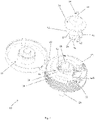
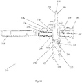
- Fig. 1 shows a perspective view of the closure 12 and the dispensing fitment 14 of the closure assembly 10.
- the closure 12 has a closure body 16 and a closure cap 18, which may be connected by a living hinge 20 that allows the cap 18 to be moved from an open position to a closed position or may be two separate components capable of being snap fit or otherwise connected.
- the manufacturer secures the closure body to a container by way of an inwardly threaded skirt 22 that extends downwardly from the closure deck 24 that engages an outwardly threaded neck portion of the container, and then the manufacturer closes the closure cap 18 against the closure body 16 to seal the container.
- the closure body also has an upper deck 26, and a tubular hub 28 that extends downwardly from the upper deck 26 for receiving the dispensing fitment 14 when the closure cap 18 is in an open position, as shown in Fig. 1 .
- the tubular hub 28 has a bottom wall 30 and an entrance orifice 32 defined within the bottom wall for receiving the dispensing fitment (see Fig. 4 ).
- a sleeve wall 34 Extending downwardly from the bottom wall 30 is a sleeve wall 34 for receiving a dispensing tube (not shown), which runs to the bottom of the container.
- the dispensing tube provides a path through which liquid may be drawn from the bottom of the container to the tubular hub 28 so that it may be dispensed through the fitment body 36 and then through the trigger sprayer.
- Fig. 3 shows how the sleeve wall 34, tubular hub 28, and dispensing fitment 14 provide a path for a liquid to flow from a dispensing tube received in the sleeve wall 34 and then through the dispensing fitment 14, though the path is blocked by the sealing boss 35 in Fig. 3 , as discussed below.
- the dispensing fitment 14 has a fitment body 36 that can be assembled with the closure body 16 to form the closure assembly 10 shown in Fig. 1 .
- the fitment body 36 has an arbor 38 that extends downwardly from the fitment body 36 that is rotatably and slidably received within the hub 28 of the closure body 16 as will be described further herein.
- a dispensing neck 48 extends upwardly from the fitment body 36, and a flow conduit 50 extends longitudinally through the arbor 38, the fitment body 36 and the dispensing neck 48, as shown in the cross sectional view of Fig. 4 .
- the dispensing neck 48 may be configured and arranged to receive the hose portion of a spray handle.
- the container walls begin to collapse inwards. This decreases the ability of the trigger sprayer to dispense liquid from the container, and it may cease the operation of the trigger sprayer entirely.
- the instant invention addresses this problem by including a sealable vent hole 52 defined on a recessed fitment seat 54 surrounding the hub 28, and radially spaced from the hub 28.
- the dispensing fitment 14 enables the consumer to selectively plug and open the vent hole 52 by rotating the fitment body 36 relative to the hub 28 of the closure body 16 to cause the fitment body 36 to move linearly within the hub 28.
- annular outwardly threaded fitment neck 80 extends upwardly from the upper deck 26 of the closure body 16 and surrounds the hub 28.
- An annular fitment seat 54 surrounds the threaded fitment neck 80.
- annular inwardly threaded sealing wall 82 extends downwardly from the fitment body. This inwardly threaded sealing wall 82 is threadably received with the outwardly threaded fitment neck 80 of the closure, and the arbor 38 is slidably and rotatably received in interfitting mating relation within the hub 28 of the closure body 16 so that the sealing wall 82 can be positioned in facing engagement with the recessed seat 54.
- the consumer may rotate the dispensing fitment 14 between an open venting position in which the sealing wall 82 is linearly displaced upwardly and not engaged with the recessed seat 54 and a closed position in which the sealing wall 80 engages the recessed seat 54 and blocks air flow through the vent hole 52.
- Figs. 1 and 3 show the fitment body 36 in the closed position so that the sealing wall 82 seals the recessed seat 54 to prevent air flow through the vent hole 52.
- the dispensing fitment may include a radially extending actuator arm 60.
- the lower surface 62 of the actuator arm 60 may include a locating tab 64 that extends downwardly from the actuator arm 60 and is capable of engaging a stop 66A corresponding to an open position and a stop 66B corresponding to the closed position.
- stops 66A, 66B are circumferentially spaced on the closure deck 24 such that when a user rotates the actuator arm 60 until the locating tab 64 contacts the stop 66B corresponding the closed position, the lower peripheral edge 84 of the fitment sealing wall 82 is in engagement with the recessed fitment seat 54 to block the vent hole 52.
- the closure assembly 10 may further include a sealing boss 35 within the flow conduit.
- the sealing boss 35 is connected to the hub 28 by a plurality of connecting ribs 76.
- the sealing boss 35 engages a lower end 78 of the arbor 28 when the dispensing fitment 14 is in the closed position, to prevent fluid from passing through the flow conduit 50.
- the bottom end of the arbor 38 is lifted out of engagement with the boss 35 to open the flow conduit.
- the instant closure assembly includes a vented closure and a dispensing fitment that form a vented closure assembly with a rotatable vented plug for a container (not shown).
- the dispensing fitment is rotatable but not threaded.
- the closure assembly 110 of the present invention includes a closure 112 and a dispensing fitment 114 that cooperate to provide a rotatable vented plug, which is particularly useful for spray bottles for home and garden products.
- the closure 112 and dispensing fitment 114 are provided separately to the consumer, with the closure removably secured to a spray bottle or other container.
- the consumer may insert the dispensing fitment 114 into the closure 112, as described below, and then connect the hose portion of a spray handle to the dispensing fitment in order to dispense a product from the container.
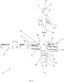
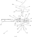
- Fig. 6 shows a perspective view of the closure 112 and the dispensing fitment 114 of the closure assembly 110.
- the closure 112 has a closure body 116 and a closure cap 118, which may be connected by a living hinge 120 that allows the cap to be moved from an open position to a closed position or may be two separate components capable of being snap fit or otherwise connected.
- the manufacturer secures the closure body 116 to a container by way of an inwardly threaded skirt 122 that extends downwardly from the closure deck 124 that engages an outwardly threaded neck portion of the container, and then the manufacturer closes the closure cap against the closure body to seal the container.
- the closure body 116 also has an upper deck 126, and a tubular hub 128 that extends downwardly from the upper deck 126 for receiving the dispensing fitment when the closure cap 118 is in an open position, as shown in Figs. 6 and 7 .
- the tubular hub 128 has a bottom wall 130 and an entrance orifice 132 defined within the bottom wall 130.
- a sleeve wall 134 Extending downwardly from the bottom wall 130 is a sleeve wall 134 for receiving a dispensing tube (not shown), which runs to the bottom of the container.
- the dispensing tube provides a path through which liquid may be drawn from the bottom of the container to the tubular hub 128 so that it may be dispensed through the dispensing fitment 114 and then through the trigger sprayer.
- Fig. 8 shows how the sleeve wall 134, tubular hub 128, and dispensing fitment 114 provide a path for a liquid to flow from a dispensing tube received in the sleeve wall 134 and then through the dispensing fitment 114.
- the dispensing fitment 114 has a fitment body 136 that can be inserted into the closure body 116 to form the closure assembly 110 shown in Fig. 7 .
- the fitment body 136 has an arbor 138 that extends downwardly from the fitment body 136 and can be inserted into the hub 128 of the closure body 116.
- the arbor 138 includes an annular locking ledge 140 on an outside surface thereof which engages with a complementary annular groove 144 formed on an inner surface 146 of the hub.
- the locking ledge 140 snaps into place within the annular groove 144, and the ledge 140 and groove 144 together maintain the dispensing fitment 114 in assembled relation with the closure body 116.
- the locking ledge 140 and groove 144 are configured to allow the arbor 138 of the fitment 114 to be slidably and rotatably received in the hub 128 of the closure body.
- a dispensing neck 148 extends upwardly from the fitment body 136, and a flow conduit 150 extends longitudinally through the arbor 138, the fitment body 136 and the dispensing neck 148, as shown in the cross sectional views of Fig. 8 and 9 .
- the dispensing neck 148 may be configured and arranged to receive the hose portion of a spray handle (not shown).
- the container walls begin to collapse inwards. This decreases the ability of the trigger sprayer to dispense liquid from the container, and it may cease the operation of the trigger sprayer entirely.
- the instant invention addresses this problem by including a sealable vent hole 152 defined on a recessed fitment seat 154 surrounding the hub 128, and radially spaced from the hub 128.
- the dispensing fitment 114 enables the consumer to selectively plug and open the vent hole 152 by rotating the fitment body 136 within the hub 128 of the closure body.
- a cantilevered arm 156 extends radially outwardly from the arbor 138 of the fitment body 136, and a vent plug 158 extends downwardly from the cantilevered arm 156 so that the vent plug can be radially aligned with the vent hole.
- the arbor 138 is slidably and rotatably received in interfitting mating relation within the hub 128 of the closure body 116 so that the cantilevered arm is positioned in facing engagement with the recessed seat.
- the consumer may rotate the dispensing fitment 114 between an open venting position in which the vent plug 158 is circumferentially displaced and not engaged with the vent hole 152 and a closed position in which the vent plug 158 is circumferentially aligned and engaged with the vent hole 152.
- the cantilever arm 156 is flexible to provide a spring bias for firm engagement of the vent plug 158 with the vent hole 152.
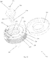
- Fig. 10 shows the locations of the vent hole 152 and the open and closed positions on the closure body 116.
- Figs. 6 and 8 show the fitment body 136 rotated to the closed position so that the vent plug 158 seals the upper end of the vent hole 152.
- the dispensing fitment 114 may include a radially extending actuator arm 160.
- the lower surface 162 of the actuator arm may include a locating tab 164 that extends downwardly from the actuator arm 160 and engages a stop 166A corresponding to an open position and a stop 166B corresponding to the closed position.
- These stops 166A, 166B are positioned such that when a user rotates the actuator arm 160 until the locating tab 164 contacts the stop 166B corresponding the closed position, the vent plug 158 engages and seals the vent hole 152.
- the instant closure assembly includes a vented closure and a dispensing fitment that form a vented closure assembly with a linearly displaceable vent sealing platform (push-pull) for a container (not shown).
- the closure assembly 210 of the present invention includes a closure 212 and a dispensing fitment 214 with a linearly displaceable vent sealing platform 215, which is particularly useful for spray bottles for home and garden products.
- the closure 212 and dispensing fitment 214 are provided separately to the consumer, with the closure 212 removably secured to a spray bottle or other container.
- the consumer may insert the dispensing fitment 214 into the closure 212, as described below, and then connect the hose portion of a spray handle (not shown) to the dispensing fitment 214 in order to dispense a product from the container.
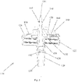
- Fig. 10 shows a perspective view of the closure 212 and the dispensing fitment 214 of the closure assembly 210 when fully assembled.
- the closure 212 has a closure body 216 and a closure cap 218, which may be connected by a living hinge 220 that allows the cap 218 to be moved from an open position to a closed position or may be two separate components capable of being snap fit or otherwise connected.
- the manufacturer secures the closure body 212 to a container by way of an inwardly threaded skirt 222 that extends downwardly from the closure deck 224 that engages an outwardly threaded neck portion of the container, and then the manufacturer closes the closure cap against the closure body to seal the container.
- the closure body 216 also has an upper deck 226, and a tubular hub 228 that extends downwardly from the upper deck for receiving the dispensing fitment 214 when the closure cap is in an open position, as shown in Fig. 12 .
- the tubular hub 228 has a bottom wall 230 and an entrance orifice 232 defined within the bottom 230 wall (see Figs. 13 and 14 ).
- a sleeve wall 234 Extending downwardly from the bottom wall is a sleeve wall 234 for receiving a dispensing tube (not shown), which runs to the bottom of the container.
- the dispensing tube provides a path through which liquid may be drawn from the bottom of the container to the tubular hub 228 so that it may be dispensed through the fitment 214 and then through the trigger sprayer.
- Fig. 13 shows how the sleeve wall 234, tubular hub 228, and dispensing fitment 214 provide a path for a liquid to flow from a dispensing tube received in the sleeve wall 234 and then through the dispensing fitment 214, though this path in Fig. 13 is blocked by the sealing boss 235, which is discussed in more detail below.
- the dispensing fitment 214 has a fitment body 236 that can be inserted into the closure body 216 to form the closure assembly 210 shown in Fig. 10 .
- the fitment body 214 has an arbor 238 that extends downwardly from the fitment body 236 and can be inserted into the hub 228 of the closure body 216.
- the arbor includes an annular locking ledge 240 on an outside surface 242 thereof which engages with a complementary annular groove 244 formed on an inner surface 246 of the hub.
- the locking ledge 240 snaps into place within the annular groove 244, and the ledge 240 and groove 244 together maintain the dispensing fitment 214 in assembled relation with the closure body 216.
- the locking ledge 240 and groove 244 are configured to allow the arbor 238 of the fitment body 236 to be slidably received in the hub 228 of the closure body 216 and linearly displaceable within the closure body 216, as discussed in more detail below.
- a dispensing neck 248 extends upwardly from the fitment body 236, and a flow conduit 250 extends longitudinally through the arbor 238, the fitment body 236 and the dispensing neck 248, as shown in the cross sectional view of Fig. 13 .
- the dispensing neck 248 may be configured and arranged to receive the hose portion of a spray handle.
- the container walls begin to collapse inwards. This decreases the ability of the trigger sprayer to dispense liquid from the container, and it may cease the operation of the trigger sprayer entirely.
- the instant invention addresses this problem by including a sealable vent hole 252 defined on a recessed fitment seat 254 surrounding the hub 228, and radially spaced from the hub 228.
- the dispensing fitment 214 enables the consumer to selectively plug and open the vent hole 252 by linearly moving the fitment body 236 within the hub 228 of the closure body 216.
- An annular sealing platform 270 extends radially outwardly from the fitment body and the annular sealing platform 270 has a lower sealing surface 272 for engaging and sealing the vent hole 252.
- the arbor 238 is slidably received in interfitting mating relation within the hub 228 of the closure body 216 so that the lower sealing surface 272 of the sealing platform 270 is positioned in facing engagement with the recessed seat 254.
- the consumer may move the dispensing fitment 214 between an open venting position in which the lower sealing surface 272 is linearly displaced upwardly and not engaged with the vent hole 252 and a closed position in which the lower sealing surface 272 engages the fitment seat 254 and blocks the vent hole 252 so that fluid may not pass through the vent hole.
- Fig. 15 shows the location of the vent hole 252 on the closure body 216.
- Figs. 10 and 13 show the fitment body 236 in the closed position so that the lower sealing surface 272 seals the upper end of the vent hole 252.
- the annular locking ledge 240 on the outside of the arbor 238 engages an annular groove 244 on the inner surface of the hub.
- the annular groove 244 has a lower edge wall 245A corresponding to the lower closed position, and an upper edge wall 245B corresponding to an open venting position.
- the locking ledge 240 and the groove 244 cooperate to maintain the dispensing fitment 214 in assembled relation with the closure body 216 and provide positive locating positions of the dispensing fitment 214 relative to the closure 212.
- Fig. 13 shows the fitment body 236 in the closed position, with the annular locking ledge 240 in contact with the lower edge 245A of the annular groove.
- the recessed fitment seat 254 may include an upstanding annular sealing wall 273 to secure the annular sealing platform in the closed position.
- the upstanding annular sealing wall 273 matingly engages with a peripheral edge 274 of the annular sealing platform 270 when the sealing platform 270 is in the closed position to create a better seal of the vent hole 252.
- the outer diameter of the peripheral edge 274 can be designed to be greater than the inner diameter of the upstanding annular sealing wall 273, forming a more secure press fit between peripheral edge 274 of the sealing platform 270 and sealing wall 273.
- the hub 228 may further include a sealing boss 235 within the flow conduit 250, as shown in Figs. 13 and 14 .
- the sealing boss 235 is connected to the hub 228 by a plurality of radial connecting ribs 278.
- the sealing boss is positioned within the flow conduit so that it engages a lower end of the arbor when the dispensing fitment is in the closed position, as shown in Fig. 13 . In this position, the sealing boss and lower end 276 of the arbor 238 cooperate to block flow through the flow conduit 250.
- the instant invention is believed to represent a significant advancement in the art which has substantial commercial merit.
Landscapes
- Engineering & Computer Science (AREA)
- Mechanical Engineering (AREA)
- Closures For Containers (AREA)
- Nozzles (AREA)
- Containers And Packaging Bodies Having A Special Means To Remove Contents (AREA)
Claims (6)
- Ensemble de bouchon (110) pour récipient d'un système de pulvérisation, l'ensemble de bouchon (110) comprenant :un bouchon (112) ; etun raccord de distribution (114),ledit bouchon (112) comportant un corps de bouchon (116) ayant une surface supérieure (126), un moyeu tubulaire (128) s'étendant vers le bas depuis ladite surface supérieure (126), et un siège de raccord en retrait (154) entourant ledit moyeu tubulaire (128),ledit moyeu tubulaire (128) ayant une paroi de fond (130) et un orifice d'entrée (132) dans ladite paroi de fond (130), ledit moyeu tubulaire (128) comportant en outre une paroi de manchon (134) s'étendant vers le bas depuis ladite paroi de fond (130) pour y recevoir un tube de distribution, ledit siège de raccord en retrait (154) comportant un évent (152) espacé radialement dudit moyeu tubulaire (128),ledit raccord de distribution (114) comportant :un corps de raccord (136),une tige (138) s'étendant vers le bas depuis ledit corps de raccord (136),un bras en porte-à-faux (156) s'étendant radialement vers l'extérieur depuis ladite tige (138),un obturateur d'évent (158) s'étendant vers le bas depuis ledit bras en porte-à-faux (156), ledit obturateur d'évent (158) étant positionné pour être aligné radialement avec ledit évent (152),un col de distribution (148) s'étendant vers le haut depuis ledit corps de raccord (136), etun conduit d'écoulement (150) s'étendant longitudinalement à travers ladite tige (138), ledit corps de raccord (136) et ledit col de distribution (148),ladite tige (138) étant reçue de manière glissante et à rotation en relation d'accouplement mutuel dans ledit moyeu tubulaire (128) dudit corps de bouchon (116), moyennant quoi ledit bras en porte-à-faux (156) est positionné en contact de face avec ledit siège de raccord en retrait (154),ledit raccord de distribution (114) étant mobile à rotation entre une position d'aération ouverte dans laquelle ledit obturateur d'évent (158) est déplacé de façon circonférentielle et n'est pas en prise avec ledit évent (152) et une position fermée dans laquelle ledit obturateur d'évent (158) est aligné de façon circonférentielle et en prise avec ledit évent (152),ladite tige (138) comportant un rebord de blocage annulaire (140) sur une surface extérieure de celle-ci qui se met en prise avec une rainure annulaire complémentaire (144) formée sur une surface intérieure dudit moyeu tubulaire (128) pour maintenir ledit raccord de distribution (114) assemblé avec ledit corps de bouchon (116).
- Ensemble de bouchon selon la revendication 1, dans lequel ledit raccord de distribution (114) comporte un bras d'actionnement s'étendant radialement (160).
- Ensemble de bouchon selon la revendication 1, dans lequel ledit raccord de distribution (114) comporte une patte de positionnement (164), et ladite surface supérieure (126) comporte des butées de positionnement espacées de façon circonférentielle (166A, 166B) correspondant auxdites positions ouverte et fermée.
- Ensemble de bouchon selon la revendication 3, dans lequel ladite patte de positionnement (164) est formée sur ledit bras d'actionnement (160).
- Ensemble de bouchon selon la revendication 1, dans lequel ledit col de distribution (148) est configuré et agencé pour recevoir une partie de tuyau d'une poignée de pulvérisation.
- Ensemble de bouchon selon la revendication 1, comprenant en outre un couvercle de bouchon (118) et une charnière film (120) reliant ledit couvercle de bouchon audit corps de bouchon, moyennant quoi ledit couvercle de bouchon est mobile entre une position ouverte et une position fermée.
Applications Claiming Priority (5)
| Application Number | Priority Date | Filing Date | Title |
|---|---|---|---|
| US201361788089P | 2013-03-15 | 2013-03-15 | |
| US201361788362P | 2013-03-15 | 2013-03-15 | |
| US201361789197P | 2013-03-15 | 2013-03-15 | |
| EP14768188.6A EP2969804B1 (fr) | 2013-03-15 | 2014-03-13 | Ensemble fermeture aérée pour un récipient de pulvérisation |
| PCT/US2014/025209 WO2014151208A2 (fr) | 2013-03-15 | 2014-03-13 | Ensemble fermeture aérée pour un récipient de pulvérisation |
Related Parent Applications (1)
| Application Number | Title | Priority Date | Filing Date |
|---|---|---|---|
| EP14768188.6A Division EP2969804B1 (fr) | 2013-03-15 | 2014-03-13 | Ensemble fermeture aérée pour un récipient de pulvérisation |
Publications (3)
| Publication Number | Publication Date |
|---|---|
| EP3498623A2 EP3498623A2 (fr) | 2019-06-19 |
| EP3498623A3 EP3498623A3 (fr) | 2019-07-03 |
| EP3498623B1 true EP3498623B1 (fr) | 2023-01-04 |
Family
ID=51581636
Family Applications (2)
| Application Number | Title | Priority Date | Filing Date |
|---|---|---|---|
| EP14768188.6A Active EP2969804B1 (fr) | 2013-03-15 | 2014-03-13 | Ensemble fermeture aérée pour un récipient de pulvérisation |
| EP19151991.7A Active EP3498623B1 (fr) | 2013-03-15 | 2014-03-13 | Ensemble de fermeture ventilée pour récipient d'aérosol |
Family Applications Before (1)
| Application Number | Title | Priority Date | Filing Date |
|---|---|---|---|
| EP14768188.6A Active EP2969804B1 (fr) | 2013-03-15 | 2014-03-13 | Ensemble fermeture aérée pour un récipient de pulvérisation |
Country Status (3)
| Country | Link |
|---|---|
| US (2) | US10201821B2 (fr) |
| EP (2) | EP2969804B1 (fr) |
| WO (1) | WO2014151208A2 (fr) |
Families Citing this family (5)
| Publication number | Priority date | Publication date | Assignee | Title |
|---|---|---|---|---|
| US10676259B1 (en) | 2018-11-15 | 2020-06-09 | Silgan Dispensing Systems Corporation | Two-part dispensing closure system with internal seal and methods of using the same |
| US11059633B2 (en) | 2019-10-31 | 2021-07-13 | Cheer Pack North America | Flip-top closure for container |
| TWI697362B (zh) * | 2019-11-06 | 2020-07-01 | 邱森玉 | 容器的噴灑結構 |
| USD980069S1 (en) | 2020-07-14 | 2023-03-07 | Ball Corporation | Metallic dispensing lid |
| US20230234759A1 (en) * | 2022-01-25 | 2023-07-27 | Helen Of Troy Limited | Poppet lid |
Family Cites Families (40)
| Publication number | Priority date | Publication date | Assignee | Title |
|---|---|---|---|---|
| US3520452A (en) * | 1968-11-29 | 1970-07-14 | Afa Corp | Leakproof container seal |
| US3780951A (en) * | 1973-01-30 | 1973-12-25 | Afa Corp | Leakproof head for hand sprayer |
| US4222500A (en) * | 1978-07-24 | 1980-09-16 | James D. Pauls, Limited | Non-propellant, duration spray dispenser with positive shut off valve |
| US4485943A (en) * | 1982-03-08 | 1984-12-04 | Joachim Czech | Dispenser for liquids or pasty products |
| AU640978B2 (en) * | 1989-12-28 | 1993-09-09 | Yoshino Kogyosho Co., Ltd. | Liquid sprayer |
| US5183185A (en) * | 1991-02-14 | 1993-02-02 | Ecopac, L. P. | Mechanically pressurized dispenser system |
| US5318206A (en) | 1992-02-24 | 1994-06-07 | Afa Products, Inc. | Trigger-piston connection |
| FR2711554B1 (fr) * | 1993-10-22 | 1995-12-22 | Oreal | Ensemble de distribution à reprise d'air commandée. |
| US5664703A (en) * | 1994-02-28 | 1997-09-09 | The Procter & Gamble Company | Pump device with collapsible pump chamber having supply container venting system and integral shipping seal |
| US5605257A (en) * | 1996-03-04 | 1997-02-25 | Beard; Walter C. | Sterile liquid squeeze-bottle-type dispenser |
| US6192797B1 (en) * | 1999-12-23 | 2001-02-27 | Sonoco Development, Inc. | Ink cartridge for automated dispensing systems |
| US6708852B2 (en) * | 2001-08-20 | 2004-03-23 | Alternative Packaging Solutions, L.P. | Non-chemical aerosol dispenser |
| US6547108B2 (en) * | 2001-08-31 | 2003-04-15 | Sonoco Development, Inc. | Pressure-activated flexible valve |
| US7913877B2 (en) * | 2003-01-21 | 2011-03-29 | Aptargroup Inc. | Aerosol mounting cup for connection to a collapsible container |
| US7686194B2 (en) * | 2003-09-03 | 2010-03-30 | Rieke Corporation | Closed loop fluid dispensing system |
| US7322493B2 (en) * | 2003-10-09 | 2008-01-29 | Polytop Corporation | Dispensing closure having complete peripheral seal |
| CN1308188C (zh) * | 2004-10-08 | 2007-04-04 | 蒋一新 | 液体包装瓶旋转盖 |
| WO2007127982A2 (fr) * | 2006-04-28 | 2007-11-08 | Pouch Pac Innovations, Llc | Poche flexible avec accessoire de bec de tube et procédé de formation |
| MX2009001545A (es) * | 2006-08-28 | 2009-04-16 | Liqui Box Canada Inc | Montaje y collar de valvula de corredera. |
| CN101553410B (zh) | 2006-12-08 | 2012-11-07 | 米德韦斯瓦科公司 | 扳机喷雾器 |
| KR101470051B1 (ko) * | 2007-08-28 | 2014-12-05 | 엔테그리스, 아이엔씨. | 유체 분배용 방법 및 장치 |
| WO2009155460A1 (fr) | 2008-06-18 | 2009-12-23 | Polytop Corporation | Fermeture de distribution d'un orifice en éventail |
| US20100108724A1 (en) | 2008-10-30 | 2010-05-06 | Gilbert Buchalter | Twist open/twist close Closure |
| US8083107B2 (en) * | 2009-04-09 | 2011-12-27 | Rodney Laible | Closed loop dispensing system with mechanical venting means |
| US20150343470A1 (en) * | 2010-01-28 | 2015-12-03 | Sun Solutions Ltd. | Spray mineral water bottle and cap of spray mineral water bottle |
| TWM399845U (en) * | 2010-07-26 | 2011-03-11 | Taiwan Vertex Production Corp | Rotary water stop bottle cap |
| BR112013009593A2 (pt) * | 2010-10-20 | 2016-07-12 | Meadwestvaco Calmar Inc | mecanismos de bombas e métodos de fabricação |
| DE102010062223A1 (de) * | 2010-11-30 | 2012-05-31 | Bericap Holding Gmbh | Leicht zu öffnender Ventilverschluss |
| US8465169B2 (en) * | 2010-12-06 | 2013-06-18 | Hung-Wen Lin | Driving shaft mechanism for ratchet wrench |
| FR2971774B1 (fr) * | 2011-02-23 | 2014-06-06 | Valois Sas | Distributeur de produit fluide |
| GB201111400D0 (en) * | 2011-07-04 | 2011-08-17 | Obrist Closures Switzerland | A closure |
| KR101233080B1 (ko) * | 2011-09-20 | 2013-02-14 | (주)연우 | 스프레이 펌프 |
| US9415401B2 (en) * | 2012-04-04 | 2016-08-16 | Alternative Packaging Solutions Llc | One turn actuated duration spray pump mechanism |
| US9027793B2 (en) * | 2012-09-17 | 2015-05-12 | Owens-Brockway Glass Container Inc. | Fitment for a container |
| US9409682B2 (en) * | 2013-03-15 | 2016-08-09 | Owens-Brockway Glass Container Inc. | Non-removable container neck ring |
| ITVI20130130A1 (it) * | 2013-05-08 | 2014-11-09 | Taplast Srl | Dispositivo per l'erogazione di fluidi. |
| US9010556B2 (en) * | 2013-06-04 | 2015-04-21 | Emil Benson | Bottle cap apparatus |
| EP3371095B1 (fr) * | 2015-11-02 | 2020-08-12 | Liqui-Box Corporation | Raccord formant bec pour la distribution de fluides à partir de sacs souples |
| US10138029B2 (en) * | 2015-12-03 | 2018-11-27 | Hyobin IM | Container lid having measuring function |
| US10280062B2 (en) * | 2016-10-20 | 2019-05-07 | Fres-Co System Usa, Inc. | Pierce at first use dispensing tap for flexible bag with filling gland and bag including the same |
-
2014
- 2014-03-13 WO PCT/US2014/025209 patent/WO2014151208A2/fr active Application Filing
- 2014-03-13 US US14/774,454 patent/US10201821B2/en active Active
- 2014-03-13 EP EP14768188.6A patent/EP2969804B1/fr active Active
- 2014-03-13 EP EP19151991.7A patent/EP3498623B1/fr active Active
-
2018
- 2018-12-10 US US16/214,250 patent/US10668492B2/en active Active
Also Published As
| Publication number | Publication date |
|---|---|
| EP3498623A3 (fr) | 2019-07-03 |
| US10668492B2 (en) | 2020-06-02 |
| WO2014151208A3 (fr) | 2014-11-06 |
| EP2969804B1 (fr) | 2019-01-16 |
| EP3498623A2 (fr) | 2019-06-19 |
| US20190105677A1 (en) | 2019-04-11 |
| EP2969804A4 (fr) | 2017-03-01 |
| US10201821B2 (en) | 2019-02-12 |
| WO2014151208A2 (fr) | 2014-09-25 |
| EP2969804A2 (fr) | 2016-01-20 |
| US20160059255A1 (en) | 2016-03-03 |
Similar Documents
| Publication | Publication Date | Title |
|---|---|---|
| US10668492B2 (en) | Vented closure assembly for a spray container | |
| CA2654309C (fr) | Cartouche de concentre a l'epreuve des enfants et contenant de dilution et de distribution associe | |
| US8622256B2 (en) | Actuator for spray container with restraint structure | |
| EP1737784B1 (fr) | Raccord rapide de tube d'apport de fluide flexible-tube immerge rigide pour pulverisateur de liquide | |
| EP3043924B1 (fr) | Pulvérisateur | |
| US6971552B2 (en) | Aerosol dispenser | |
| US8662353B2 (en) | Protective cap for dispensers and container comprising said cap | |
| US20190077580A1 (en) | Child resistant aerosol actuator | |
| US20160362229A1 (en) | Closures for bladder ports | |
| JP6647178B2 (ja) | ねじユニット及びねじ容器 | |
| EP3526130A1 (fr) | Récipient | |
| US4925068A (en) | Liquid dispenser | |
| WO2016085966A1 (fr) | Couvercle de distribution d'huile | |
| JP6116259B2 (ja) | 吐出器 | |
| US20210325226A1 (en) | Measured dose dispenser and methods of using the same | |
| US10889485B2 (en) | Dispensing system including a dispensing tap and an integrated measuring cap/cup and holder | |
| JP3124569U (ja) | 容器の口栓装置 | |
| JP6332694B2 (ja) | 吐出兼用噴出容器 | |
| EP4196402B1 (fr) | Bouchon et récipient | |
| KR200462267Y1 (ko) | 액상 용기의 캡 구조 | |
| JP2018122881A (ja) | 二剤混合容器 | |
| JP2018203303A (ja) | 吐出容器 | |
| JP2019119524A (ja) | 噴射操作支援器具 | |
| JP4968733B2 (ja) | 液体噴出器 | |
| WO2008042737A3 (fr) | Fermeture de distribution pour applications aseptiques humides et à basse pression |
Legal Events
| Date | Code | Title | Description |
|---|---|---|---|
| PUAI | Public reference made under article 153(3) epc to a published international application that has entered the european phase |
Free format text: ORIGINAL CODE: 0009012 |
|
| STAA | Information on the status of an ep patent application or granted ep patent |
Free format text: STATUS: THE APPLICATION HAS BEEN PUBLISHED |
|
| PUAL | Search report despatched |
Free format text: ORIGINAL CODE: 0009013 |
|
| AC | Divisional application: reference to earlier application |
Ref document number: 2969804 Country of ref document: EP Kind code of ref document: P |
|
| AK | Designated contracting states |
Kind code of ref document: A2 Designated state(s): AL AT BE BG CH CY CZ DE DK EE ES FI FR GB GR HR HU IE IS IT LI LT LU LV MC MK MT NL NO PL PT RO RS SE SI SK SM TR |
|
| AK | Designated contracting states |
Kind code of ref document: A3 Designated state(s): AL AT BE BG CH CY CZ DE DK EE ES FI FR GB GR HR HU IE IS IT LI LT LU LV MC MK MT NL NO PL PT RO RS SE SI SK SM TR |
|
| RIC1 | Information provided on ipc code assigned before grant |
Ipc: B65D 51/16 20060101ALI20190527BHEP Ipc: B65D 25/40 20060101AFI20190527BHEP Ipc: B65D 47/32 20060101ALI20190527BHEP |
|
| STAA | Information on the status of an ep patent application or granted ep patent |
Free format text: STATUS: REQUEST FOR EXAMINATION WAS MADE |
|
| 17P | Request for examination filed |
Effective date: 20190816 |
|
| RBV | Designated contracting states (corrected) |
Designated state(s): AL AT BE BG CH CY CZ DE DK EE ES FI FR GB GR HR HU IE IS IT LI LT LU LV MC MK MT NL NO PL PT RO RS SE SI SK SM TR |
|
| STAA | Information on the status of an ep patent application or granted ep patent |
Free format text: STATUS: EXAMINATION IS IN PROGRESS |
|
| 17Q | First examination report despatched |
Effective date: 20191212 |
|
| STAA | Information on the status of an ep patent application or granted ep patent |
Free format text: STATUS: EXAMINATION IS IN PROGRESS |
|
| GRAP | Despatch of communication of intention to grant a patent |
Free format text: ORIGINAL CODE: EPIDOSNIGR1 |
|
| STAA | Information on the status of an ep patent application or granted ep patent |
Free format text: STATUS: GRANT OF PATENT IS INTENDED |
|
| INTG | Intention to grant announced |
Effective date: 20220729 |
|
| GRAS | Grant fee paid |
Free format text: ORIGINAL CODE: EPIDOSNIGR3 |
|
| GRAA | (expected) grant |
Free format text: ORIGINAL CODE: 0009210 |
|
| STAA | Information on the status of an ep patent application or granted ep patent |
Free format text: STATUS: THE PATENT HAS BEEN GRANTED |
|
| AC | Divisional application: reference to earlier application |
Ref document number: 2969804 Country of ref document: EP Kind code of ref document: P |
|
| AK | Designated contracting states |
Kind code of ref document: B1 Designated state(s): AL AT BE BG CH CY CZ DE DK EE ES FI FR GB GR HR HU IE IS IT LI LT LU LV MC MK MT NL NO PL PT RO RS SE SI SK SM TR |
|
| REG | Reference to a national code |
Ref country code: GB Ref legal event code: FG4D |
|
| REG | Reference to a national code |
Ref country code: DE Ref legal event code: R096 Ref document number: 602014086041 Country of ref document: DE |
|
| REG | Reference to a national code |
Ref country code: CH Ref legal event code: EP |
|
| REG | Reference to a national code |
Ref country code: AT Ref legal event code: REF Ref document number: 1541797 Country of ref document: AT Kind code of ref document: T Effective date: 20230115 |
|
| REG | Reference to a national code |
Ref country code: IE Ref legal event code: FG4D |
|
| REG | Reference to a national code |
Ref country code: LT Ref legal event code: MG9D |
|
| REG | Reference to a national code |
Ref country code: NL Ref legal event code: MP Effective date: 20230104 |
|
| REG | Reference to a national code |
Ref country code: AT Ref legal event code: MK05 Ref document number: 1541797 Country of ref document: AT Kind code of ref document: T Effective date: 20230104 |
|
| PG25 | Lapsed in a contracting state [announced via postgrant information from national office to epo] |
Ref country code: NL Free format text: LAPSE BECAUSE OF FAILURE TO SUBMIT A TRANSLATION OF THE DESCRIPTION OR TO PAY THE FEE WITHIN THE PRESCRIBED TIME-LIMIT Effective date: 20230104 |
|
| PG25 | Lapsed in a contracting state [announced via postgrant information from national office to epo] |
Ref country code: RS Free format text: LAPSE BECAUSE OF FAILURE TO SUBMIT A TRANSLATION OF THE DESCRIPTION OR TO PAY THE FEE WITHIN THE PRESCRIBED TIME-LIMIT Effective date: 20230104 Ref country code: PT Free format text: LAPSE BECAUSE OF FAILURE TO SUBMIT A TRANSLATION OF THE DESCRIPTION OR TO PAY THE FEE WITHIN THE PRESCRIBED TIME-LIMIT Effective date: 20230504 Ref country code: NO Free format text: LAPSE BECAUSE OF FAILURE TO SUBMIT A TRANSLATION OF THE DESCRIPTION OR TO PAY THE FEE WITHIN THE PRESCRIBED TIME-LIMIT Effective date: 20230404 Ref country code: LV Free format text: LAPSE BECAUSE OF FAILURE TO SUBMIT A TRANSLATION OF THE DESCRIPTION OR TO PAY THE FEE WITHIN THE PRESCRIBED TIME-LIMIT Effective date: 20230104 Ref country code: LT Free format text: LAPSE BECAUSE OF FAILURE TO SUBMIT A TRANSLATION OF THE DESCRIPTION OR TO PAY THE FEE WITHIN THE PRESCRIBED TIME-LIMIT Effective date: 20230104 Ref country code: HR Free format text: LAPSE BECAUSE OF FAILURE TO SUBMIT A TRANSLATION OF THE DESCRIPTION OR TO PAY THE FEE WITHIN THE PRESCRIBED TIME-LIMIT Effective date: 20230104 Ref country code: ES Free format text: LAPSE BECAUSE OF FAILURE TO SUBMIT A TRANSLATION OF THE DESCRIPTION OR TO PAY THE FEE WITHIN THE PRESCRIBED TIME-LIMIT Effective date: 20230104 Ref country code: AT Free format text: LAPSE BECAUSE OF FAILURE TO SUBMIT A TRANSLATION OF THE DESCRIPTION OR TO PAY THE FEE WITHIN THE PRESCRIBED TIME-LIMIT Effective date: 20230104 |
|
| PG25 | Lapsed in a contracting state [announced via postgrant information from national office to epo] |
Ref country code: SE Free format text: LAPSE BECAUSE OF FAILURE TO SUBMIT A TRANSLATION OF THE DESCRIPTION OR TO PAY THE FEE WITHIN THE PRESCRIBED TIME-LIMIT Effective date: 20230104 Ref country code: PL Free format text: LAPSE BECAUSE OF FAILURE TO SUBMIT A TRANSLATION OF THE DESCRIPTION OR TO PAY THE FEE WITHIN THE PRESCRIBED TIME-LIMIT Effective date: 20230104 Ref country code: IS Free format text: LAPSE BECAUSE OF FAILURE TO SUBMIT A TRANSLATION OF THE DESCRIPTION OR TO PAY THE FEE WITHIN THE PRESCRIBED TIME-LIMIT Effective date: 20230504 Ref country code: GR Free format text: LAPSE BECAUSE OF FAILURE TO SUBMIT A TRANSLATION OF THE DESCRIPTION OR TO PAY THE FEE WITHIN THE PRESCRIBED TIME-LIMIT Effective date: 20230405 Ref country code: FI Free format text: LAPSE BECAUSE OF FAILURE TO SUBMIT A TRANSLATION OF THE DESCRIPTION OR TO PAY THE FEE WITHIN THE PRESCRIBED TIME-LIMIT Effective date: 20230104 |
|
| REG | Reference to a national code |
Ref country code: DE Ref legal event code: R097 Ref document number: 602014086041 Country of ref document: DE |
|
| PG25 | Lapsed in a contracting state [announced via postgrant information from national office to epo] |
Ref country code: SM Free format text: LAPSE BECAUSE OF FAILURE TO SUBMIT A TRANSLATION OF THE DESCRIPTION OR TO PAY THE FEE WITHIN THE PRESCRIBED TIME-LIMIT Effective date: 20230104 Ref country code: RO Free format text: LAPSE BECAUSE OF FAILURE TO SUBMIT A TRANSLATION OF THE DESCRIPTION OR TO PAY THE FEE WITHIN THE PRESCRIBED TIME-LIMIT Effective date: 20230104 Ref country code: MC Free format text: LAPSE BECAUSE OF FAILURE TO SUBMIT A TRANSLATION OF THE DESCRIPTION OR TO PAY THE FEE WITHIN THE PRESCRIBED TIME-LIMIT Effective date: 20230104 Ref country code: EE Free format text: LAPSE BECAUSE OF FAILURE TO SUBMIT A TRANSLATION OF THE DESCRIPTION OR TO PAY THE FEE WITHIN THE PRESCRIBED TIME-LIMIT Effective date: 20230104 Ref country code: DK Free format text: LAPSE BECAUSE OF FAILURE TO SUBMIT A TRANSLATION OF THE DESCRIPTION OR TO PAY THE FEE WITHIN THE PRESCRIBED TIME-LIMIT Effective date: 20230104 Ref country code: CZ Free format text: LAPSE BECAUSE OF FAILURE TO SUBMIT A TRANSLATION OF THE DESCRIPTION OR TO PAY THE FEE WITHIN THE PRESCRIBED TIME-LIMIT Effective date: 20230104 |
|
| REG | Reference to a national code |
Ref country code: CH Ref legal event code: PL |
|
| PLBE | No opposition filed within time limit |
Free format text: ORIGINAL CODE: 0009261 |
|
| STAA | Information on the status of an ep patent application or granted ep patent |
Free format text: STATUS: NO OPPOSITION FILED WITHIN TIME LIMIT |
|
| PG25 | Lapsed in a contracting state [announced via postgrant information from national office to epo] |
Ref country code: SK Free format text: LAPSE BECAUSE OF FAILURE TO SUBMIT A TRANSLATION OF THE DESCRIPTION OR TO PAY THE FEE WITHIN THE PRESCRIBED TIME-LIMIT Effective date: 20230104 |
|
| REG | Reference to a national code |
Ref country code: BE Ref legal event code: MM Effective date: 20230331 |
|
| 26N | No opposition filed |
Effective date: 20231005 |
|
| PG25 | Lapsed in a contracting state [announced via postgrant information from national office to epo] |
Ref country code: LU Free format text: LAPSE BECAUSE OF NON-PAYMENT OF DUE FEES Effective date: 20230313 |
|
| REG | Reference to a national code |
Ref country code: IE Ref legal event code: MM4A |
|
| PG25 | Lapsed in a contracting state [announced via postgrant information from national office to epo] |
Ref country code: SI Free format text: LAPSE BECAUSE OF FAILURE TO SUBMIT A TRANSLATION OF THE DESCRIPTION OR TO PAY THE FEE WITHIN THE PRESCRIBED TIME-LIMIT Effective date: 20230104 Ref country code: LI Free format text: LAPSE BECAUSE OF NON-PAYMENT OF DUE FEES Effective date: 20230331 Ref country code: IE Free format text: LAPSE BECAUSE OF NON-PAYMENT OF DUE FEES Effective date: 20230313 Ref country code: FR Free format text: LAPSE BECAUSE OF NON-PAYMENT OF DUE FEES Effective date: 20230331 Ref country code: CH Free format text: LAPSE BECAUSE OF NON-PAYMENT OF DUE FEES Effective date: 20230331 |
|
| PG25 | Lapsed in a contracting state [announced via postgrant information from national office to epo] |
Ref country code: BE Free format text: LAPSE BECAUSE OF NON-PAYMENT OF DUE FEES Effective date: 20230331 |
|
| PGFP | Annual fee paid to national office [announced via postgrant information from national office to epo] |
Ref country code: DE Payment date: 20240327 Year of fee payment: 11 Ref country code: GB Payment date: 20240327 Year of fee payment: 11 |