EP3498203A1 - Sondenapplikator - Google Patents
Sondenapplikator Download PDFInfo
- Publication number
- EP3498203A1 EP3498203A1 EP17206694.6A EP17206694A EP3498203A1 EP 3498203 A1 EP3498203 A1 EP 3498203A1 EP 17206694 A EP17206694 A EP 17206694A EP 3498203 A1 EP3498203 A1 EP 3498203A1
- Authority
- EP
- European Patent Office
- Prior art keywords
- probe
- shaft
- applicator according
- housing
- probe applicator
- Prior art date
- Legal status (The legal status is an assumption and is not a legal conclusion. Google has not performed a legal analysis and makes no representation as to the accuracy of the status listed.)
- Granted
Links
Images


Classifications
-
- A—HUMAN NECESSITIES
- A61—MEDICAL OR VETERINARY SCIENCE; HYGIENE
- A61B—DIAGNOSIS; SURGERY; IDENTIFICATION
- A61B1/00—Instruments for performing medical examinations of the interior of cavities or tubes of the body by visual or photographical inspection, e.g. endoscopes; Illuminating arrangements therefor
- A61B1/005—Flexible endoscopes
- A61B1/01—Guiding arrangements therefore
-
- A—HUMAN NECESSITIES
- A61—MEDICAL OR VETERINARY SCIENCE; HYGIENE
- A61B—DIAGNOSIS; SURGERY; IDENTIFICATION
- A61B18/00—Surgical instruments, devices or methods for transferring non-mechanical forms of energy to or from the body
- A61B18/04—Surgical instruments, devices or methods for transferring non-mechanical forms of energy to or from the body by heating
- A61B18/12—Surgical instruments, devices or methods for transferring non-mechanical forms of energy to or from the body by heating by passing a current through the tissue to be heated, e.g. high-frequency current
- A61B18/14—Probes or electrodes therefor
- A61B18/1482—Probes or electrodes therefor having a long rigid shaft for accessing the inner body transcutaneously in minimal invasive surgery, e.g. laparoscopy
-
- A—HUMAN NECESSITIES
- A61—MEDICAL OR VETERINARY SCIENCE; HYGIENE
- A61B—DIAGNOSIS; SURGERY; IDENTIFICATION
- A61B1/00—Instruments for performing medical examinations of the interior of cavities or tubes of the body by visual or photographical inspection, e.g. endoscopes; Illuminating arrangements therefor
- A61B1/00112—Connection or coupling means
- A61B1/00114—Electrical cables in or with an endoscope
-
- A—HUMAN NECESSITIES
- A61—MEDICAL OR VETERINARY SCIENCE; HYGIENE
- A61B—DIAGNOSIS; SURGERY; IDENTIFICATION
- A61B1/00—Instruments for performing medical examinations of the interior of cavities or tubes of the body by visual or photographical inspection, e.g. endoscopes; Illuminating arrangements therefor
- A61B1/00112—Connection or coupling means
- A61B1/00121—Connectors, fasteners and adapters, e.g. on the endoscope handle
- A61B1/00124—Connectors, fasteners and adapters, e.g. on the endoscope handle electrical, e.g. electrical plug-and-socket connection
-
- A—HUMAN NECESSITIES
- A61—MEDICAL OR VETERINARY SCIENCE; HYGIENE
- A61B—DIAGNOSIS; SURGERY; IDENTIFICATION
- A61B1/00—Instruments for performing medical examinations of the interior of cavities or tubes of the body by visual or photographical inspection, e.g. endoscopes; Illuminating arrangements therefor
- A61B1/005—Flexible endoscopes
- A61B1/0051—Flexible endoscopes with controlled bending of insertion part
-
- A—HUMAN NECESSITIES
- A61—MEDICAL OR VETERINARY SCIENCE; HYGIENE
- A61B—DIAGNOSIS; SURGERY; IDENTIFICATION
- A61B1/00—Instruments for performing medical examinations of the interior of cavities or tubes of the body by visual or photographical inspection, e.g. endoscopes; Illuminating arrangements therefor
- A61B1/005—Flexible endoscopes
- A61B1/0051—Flexible endoscopes with controlled bending of insertion part
- A61B1/0052—Constructional details of control elements, e.g. handles
-
- A—HUMAN NECESSITIES
- A61—MEDICAL OR VETERINARY SCIENCE; HYGIENE
- A61B—DIAGNOSIS; SURGERY; IDENTIFICATION
- A61B1/00—Instruments for performing medical examinations of the interior of cavities or tubes of the body by visual or photographical inspection, e.g. endoscopes; Illuminating arrangements therefor
- A61B1/313—Instruments for performing medical examinations of the interior of cavities or tubes of the body by visual or photographical inspection, e.g. endoscopes; Illuminating arrangements therefor for introducing through surgical openings, e.g. laparoscopes
- A61B1/3132—Instruments for performing medical examinations of the interior of cavities or tubes of the body by visual or photographical inspection, e.g. endoscopes; Illuminating arrangements therefor for introducing through surgical openings, e.g. laparoscopes for laparoscopy
-
- A—HUMAN NECESSITIES
- A61—MEDICAL OR VETERINARY SCIENCE; HYGIENE
- A61B—DIAGNOSIS; SURGERY; IDENTIFICATION
- A61B10/00—Instruments for taking body samples for diagnostic purposes; Other methods or instruments for diagnosis, e.g. for vaccination diagnosis, sex determination or ovulation-period determination; Throat striking implements
- A61B10/02—Instruments for taking cell samples or for biopsy
- A61B10/04—Endoscopic instruments, e.g. catheter-type instruments
-
- A—HUMAN NECESSITIES
- A61—MEDICAL OR VETERINARY SCIENCE; HYGIENE
- A61B—DIAGNOSIS; SURGERY; IDENTIFICATION
- A61B17/00—Surgical instruments, devices or methods
-
- A—HUMAN NECESSITIES
- A61—MEDICAL OR VETERINARY SCIENCE; HYGIENE
- A61B—DIAGNOSIS; SURGERY; IDENTIFICATION
- A61B17/00—Surgical instruments, devices or methods
- A61B17/34—Trocars; Puncturing needles
- A61B17/3417—Details of tips or shafts, e.g. grooves, expandable, bendable; Multiple coaxial sliding cannulas, e.g. for dilating
-
- A—HUMAN NECESSITIES
- A61—MEDICAL OR VETERINARY SCIENCE; HYGIENE
- A61B—DIAGNOSIS; SURGERY; IDENTIFICATION
- A61B17/00—Surgical instruments, devices or methods
- A61B17/34—Trocars; Puncturing needles
- A61B17/3417—Details of tips or shafts, e.g. grooves, expandable, bendable; Multiple coaxial sliding cannulas, e.g. for dilating
- A61B17/3421—Cannulas
-
- A—HUMAN NECESSITIES
- A61—MEDICAL OR VETERINARY SCIENCE; HYGIENE
- A61B—DIAGNOSIS; SURGERY; IDENTIFICATION
- A61B18/00—Surgical instruments, devices or methods for transferring non-mechanical forms of energy to or from the body
-
- A—HUMAN NECESSITIES
- A61—MEDICAL OR VETERINARY SCIENCE; HYGIENE
- A61B—DIAGNOSIS; SURGERY; IDENTIFICATION
- A61B18/00—Surgical instruments, devices or methods for transferring non-mechanical forms of energy to or from the body
- A61B18/04—Surgical instruments, devices or methods for transferring non-mechanical forms of energy to or from the body by heating
- A61B18/12—Surgical instruments, devices or methods for transferring non-mechanical forms of energy to or from the body by heating by passing a current through the tissue to be heated, e.g. high-frequency current
- A61B18/14—Probes or electrodes therefor
- A61B18/1402—Probes for open surgery
-
- A—HUMAN NECESSITIES
- A61—MEDICAL OR VETERINARY SCIENCE; HYGIENE
- A61M—DEVICES FOR INTRODUCING MEDIA INTO, OR ONTO, THE BODY; DEVICES FOR TRANSDUCING BODY MEDIA OR FOR TAKING MEDIA FROM THE BODY; DEVICES FOR PRODUCING OR ENDING SLEEP OR STUPOR
- A61M25/00—Catheters; Hollow probes
- A61M25/0067—Catheters; Hollow probes characterised by the distal end, e.g. tips
- A61M25/0068—Static characteristics of the catheter tip, e.g. shape, atraumatic tip, curved tip or tip structure
-
- H—ELECTRICITY
- H01—ELECTRIC ELEMENTS
- H01R—ELECTRICALLY-CONDUCTIVE CONNECTIONS; STRUCTURAL ASSOCIATIONS OF A PLURALITY OF MUTUALLY-INSULATED ELECTRICAL CONNECTING ELEMENTS; COUPLING DEVICES; CURRENT COLLECTORS
- H01R13/00—Details of coupling devices of the kinds covered by groups H01R12/70 or H01R24/00 - H01R33/00
- H01R13/005—Electrical coupling combined with fluidic coupling
-
- A—HUMAN NECESSITIES
- A61—MEDICAL OR VETERINARY SCIENCE; HYGIENE
- A61B—DIAGNOSIS; SURGERY; IDENTIFICATION
- A61B17/00—Surgical instruments, devices or methods
- A61B17/00234—Surgical instruments, devices or methods for minimally invasive surgery
- A61B2017/00292—Surgical instruments, devices or methods for minimally invasive surgery mounted on or guided by flexible, e.g. catheter-like, means
- A61B2017/003—Steerable
-
- A—HUMAN NECESSITIES
- A61—MEDICAL OR VETERINARY SCIENCE; HYGIENE
- A61B—DIAGNOSIS; SURGERY; IDENTIFICATION
- A61B17/00—Surgical instruments, devices or methods
- A61B2017/00477—Coupling
-
- A—HUMAN NECESSITIES
- A61—MEDICAL OR VETERINARY SCIENCE; HYGIENE
- A61B—DIAGNOSIS; SURGERY; IDENTIFICATION
- A61B18/00—Surgical instruments, devices or methods for transferring non-mechanical forms of energy to or from the body
- A61B2018/00005—Cooling or heating of the probe or tissue immediately surrounding the probe
- A61B2018/00011—Cooling or heating of the probe or tissue immediately surrounding the probe with fluids
-
- A—HUMAN NECESSITIES
- A61—MEDICAL OR VETERINARY SCIENCE; HYGIENE
- A61B—DIAGNOSIS; SURGERY; IDENTIFICATION
- A61B18/00—Surgical instruments, devices or methods for transferring non-mechanical forms of energy to or from the body
- A61B2018/00005—Cooling or heating of the probe or tissue immediately surrounding the probe
- A61B2018/00011—Cooling or heating of the probe or tissue immediately surrounding the probe with fluids
- A61B2018/00017—Cooling or heating of the probe or tissue immediately surrounding the probe with fluids with gas
-
- A—HUMAN NECESSITIES
- A61—MEDICAL OR VETERINARY SCIENCE; HYGIENE
- A61B—DIAGNOSIS; SURGERY; IDENTIFICATION
- A61B18/00—Surgical instruments, devices or methods for transferring non-mechanical forms of energy to or from the body
- A61B2018/00053—Mechanical features of the instrument of device
- A61B2018/00172—Connectors and adapters therefor
- A61B2018/00178—Electrical connectors
-
- A—HUMAN NECESSITIES
- A61—MEDICAL OR VETERINARY SCIENCE; HYGIENE
- A61B—DIAGNOSIS; SURGERY; IDENTIFICATION
- A61B18/00—Surgical instruments, devices or methods for transferring non-mechanical forms of energy to or from the body
- A61B2018/00053—Mechanical features of the instrument of device
- A61B2018/00184—Moving parts
-
- A—HUMAN NECESSITIES
- A61—MEDICAL OR VETERINARY SCIENCE; HYGIENE
- A61B—DIAGNOSIS; SURGERY; IDENTIFICATION
- A61B2218/00—Details of surgical instruments, devices or methods for transferring non-mechanical forms of energy to or from the body
- A61B2218/001—Details of surgical instruments, devices or methods for transferring non-mechanical forms of energy to or from the body having means for irrigation and/or aspiration of substances to and/or from the surgical site
-
- A—HUMAN NECESSITIES
- A61—MEDICAL OR VETERINARY SCIENCE; HYGIENE
- A61B—DIAGNOSIS; SURGERY; IDENTIFICATION
- A61B2218/00—Details of surgical instruments, devices or methods for transferring non-mechanical forms of energy to or from the body
- A61B2218/001—Details of surgical instruments, devices or methods for transferring non-mechanical forms of energy to or from the body having means for irrigation and/or aspiration of substances to and/or from the surgical site
- A61B2218/002—Irrigation
-
- A—HUMAN NECESSITIES
- A61—MEDICAL OR VETERINARY SCIENCE; HYGIENE
- A61M—DEVICES FOR INTRODUCING MEDIA INTO, OR ONTO, THE BODY; DEVICES FOR TRANSDUCING BODY MEDIA OR FOR TAKING MEDIA FROM THE BODY; DEVICES FOR PRODUCING OR ENDING SLEEP OR STUPOR
- A61M25/00—Catheters; Hollow probes
- A61M25/01—Introducing, guiding, advancing, emplacing or holding catheters
- A61M25/09—Guide wires
- A61M2025/09175—Guide wires having specific characteristics at the distal tip
-
- A—HUMAN NECESSITIES
- A61—MEDICAL OR VETERINARY SCIENCE; HYGIENE
- A61M—DEVICES FOR INTRODUCING MEDIA INTO, OR ONTO, THE BODY; DEVICES FOR TRANSDUCING BODY MEDIA OR FOR TAKING MEDIA FROM THE BODY; DEVICES FOR PRODUCING OR ENDING SLEEP OR STUPOR
- A61M25/00—Catheters; Hollow probes
- A61M25/01—Introducing, guiding, advancing, emplacing or holding catheters
- A61M25/09—Guide wires
-
- H—ELECTRICITY
- H01—ELECTRIC ELEMENTS
- H01R—ELECTRICALLY-CONDUCTIVE CONNECTIONS; STRUCTURAL ASSOCIATIONS OF A PLURALITY OF MUTUALLY-INSULATED ELECTRICAL CONNECTING ELEMENTS; COUPLING DEVICES; CURRENT COLLECTORS
- H01R2201/00—Connectors or connections adapted for particular applications
- H01R2201/12—Connectors or connections adapted for particular applications for medicine and surgery
Definitions
- the invention relates to an applicator for laparoscopic use of flexible probes.
- a medical instrument having an elongate shaft is known, the proximal end of which is held on a handle-housing.
- an insertion opening is provided, through which a probe can be inserted through the housing into the shaft.
- the probe extends through the shaft and can protrude from the distal end thereof.
- the shaft then serves to extract fluids from the treatment site, which can be controlled via corresponding valves on the handle.
- connections for fluid lines for rinsing and suction are arranged. The probe is in turn connected to an electrical source.
- a probe insertion opening is provided, through which a flexible probe can be inserted into the housing and through it into the shaft.
- the housing equipped with the probe can then be manually positioned and moved by means of the handle provided on the housing, for example, to introduce the shaft through a small access opening in the body of the patient and there by activating the probe and movement of the housing with the shaft desired to perform surgical interventions.
- one or more control elements for activating and deactivating the probe are arranged on the housing, in particular on its handle.
- a cable extends to a plug to transmit signal output from an operation of the control to a plug or other connector.
- the signal line extending through the cable may be an electrical line, a fluid line, a waveguide such as an optical fiber or the like.
- the probe applicator has a connection device that is set up to connect a probe in order to supply it with operating medium.
- the operating medium can be electric current, a liquid or gaseous fluid, light energy or the like.
- the connection device is provided on the plug, via which the probe applicator is to be connected to a supply device.
- the connection device can also be formed separately from the plug and be formed, for example, by a socket arrangement which is connected to the plug via a flexible line.
- the connection device can also be arranged on the housing.
- the probe applicator according to the invention allows the use of a variety of known from endoscopy flexible probes outside of endoscopes.
- the user may use the probe applicator as in laparoscopic procedures. This makes endoscopic probes useful for surgical disciplines in general surgery, visceral surgery, gynecology, urology, and ear, nose and throat (ENT).
- the rigid shaft of the probe applicator stabilizes flexible probes over a length of up to 45 or more centimeters. This makes it possible to use flexible probes in laparoscopy and mini-laparoscopy without having to provide separate rigid instruments with the same function.
- the probe applicator according to the invention opens the operation of the probes, in particular by means of manual activation, which is an important aspect in surgical applications.
- the surgeon can perform both the positioning, movement and guidance, as well as the activation and deactivation of the probe with one hand on the housing, ie on the handle and the controls thereon.
- the stem is slender and long, with its diameter preferably at most 5 mm and in some applications at most 3 mm.
- the length of the shaft preferably exceeds at least 100 mm, more preferably at least 350 mm or 450 mm.
- the shaft is stiff, in particular pressure and bending stiff, to be able to position and specifically move its distal end in the body of the patient by moving the handle and housing.
- an angulation means formed, for example, by a flexible tubular portion, a bellows-type portion or the like which is convertible from a stretched shape to an arcuate shape. It is sufficient if the Abwinkelungs worn can perform a pivoting movement about a single axis.
- the flexible section curves around a transverse to the shaft, this non-cutting axis of curvature.
- the bending device preferably has only one degree of freedom of movement, namely a degree of freedom of pivoting movement.
- the shaft may have an additional degree of freedom, namely rotation about its longitudinal axis.
- the shaft can be rotated by movement of the housing or alternatively by rotation of the shaft on the housing about its longitudinal direction.
- the surgeon can move out of the shaft end of the probe on a conical surface, wherein the opening angle of this cone is variable by adjusting the Abwinkelungs observed.
- the probe insertion opening can also be provided with a locking device for axial fixation of the probe, so that the surgeon removes the probe from the shaft push out or retract distally and then fix this position.
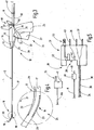
- FIG. 1 a probe applicator 10 is illustrated, which is adapted for receiving flexible probes, such as the probe 11, in order to be able to perform laparoscopic interventions with this probe 11.
- the probe applicator 10 in the manner of a laparoscopic instrument on an elongated shaft 12, the proximal end 13 is held in or on a shaft receptacle 14.
- the shaft receptacle 14 is rotatable about the longitudinal axis of the shaft 12, but it may also be rigid, ie formed or arranged non-rotatable with respect to a housing 15.
- FIG. 2 illustrates the probe applicator 10 without probe 11. To better illustrate the basic structure of the probe applicator 10 this is in FIG. 3 illustrated again with probe 11 in a schematic schematic diagram.
- the shaft 12 is formed by a slender tube whose diameter preferably does not exceed 5 mm and whose length is preferably greater than 200 mm.
- the shaft length can be up to 500 mm and in special cases more.
- the tube from which the stem 12 is formed may be made of metal or plastic, and preferably is so rigid that when inserted through a small opening in the body of a patient, it is positioned in the interior of the body by movement of its proximal end 13 can be moved so that the distal end 16 of the shaft 12 assumes desired positions or performs movements.
- the shaft 12 is much stiffer than the comparatively flexible probe 11, which is typically provided for endoscopic use and which extends through a longitudinally extending lumen 17 of the shaft 12 so that they protrude from the shaft 12 with one end 18 can.
- the shaft 12 may have a flexible portion 19, which in FIG. 4 is separately illustrated. It serves to angle the end of the shaft 12, which may be formed by a rigid pipe section 20.
- the distal end of the stem can be transformed from a straight (elongate) shape to an arcuate shape that curves about a curvature axis 21 that is oriented transverse to and extends outside of the stem 2.
- the flexible portion 19 may, as in FIG. 4 is indicated schematically, have different axial stiffnesses on diametrically opposite sides. For example, it may have a well compressible region 22 on the side facing the axis of curvature 21, while a region 23 which is less readily longitudinally compatable is formed on an opposite side. In this configuration, the flexible portion 19 forms an angle device 24. However, this may also be formed in any other way, which allows a targeted transfer of the distal end of the shaft from a stretched shape into an angled shape.
- an actuator 26 for example in the form of a pivotally mounted in or on the housing 15 lever 27, is provided.
- This lever or other handle can, via a suitable transmission, to which a power transmission means 28, for example in the form of a traction means 29, belongs, an actuating force of the actuator 26 transmitted to the Abwinkel worn 24.
- the traction means 29 may be connected to the lever 27 either directly or via a suitable gear mechanism proximal to the lever 27 and distally to the end portion 20, extending from the housing 15 through the shaft 12 to the distal end 16 of FIG Shaft 12 extends. If it is stretched, it compresses the area 22 axially, as a result of which the flexible section 19 curves laterally.
- the housing 15 is also connected via a cable 30 to a plug 31, which serves to connect the probe applicator 10 to a feeding device.
- a plug 31 which serves to connect the probe applicator 10 to a feeding device.
- the plug 31 may be configured to transmit control signals from the probe applicator 10, in particular from controls 32, 33 provided thereon, to the serving device.
- the control elements 32, 33 may be, for example, electrical switches whose switching state is via lines 34, 35 (FIG. FIG. 5 ), which extend through the cable 30, are given to corresponding pins 36, 37 on the plug 31.
- the switch 32 can enable the flow of current through a diode in a current direction between the two lines 34, 35, while the switch 33 releases the flow of current via another polarized diode in the opposite direction between the two lines 34, 35. In this way it can be distinguished at the two pins 36, 37, whether no switch, a switch or both switches are actuated.
- Other interconnections are possible, for example, all switches can be connected to a common reference potential line and an individual signal line.
- one or more other signal lines such as optical waveguides or the like may be provided, wherein at least one control element 32 and / or 33 then, for example, the reflection properties at the end of such optical waveguide to effect a signaling.
- the plug 31 contains a connecting device 38 for the probe 11.
- the connecting device 38 may be, for example, an opening 39 formed in the plug 31 into which a probe plug 40 provided at the proximal end of the probe 11 can be inserted. This serves to supply the probe 11 with its operating medium.
- the probe plug 40 may be as shown in FIG FIG. 5 is shown in a first variant, having an electrical contact 41, which is associated with a provided in the opening 39 contact socket 42 or other contact means is or are. This contact socket 42 is electrically connected to a corresponding pin 43 of the plug 31.
- the probe 11 may, as in particular FIG. 1 and 2 be connected via suitable brackets 44 to 47 or by other suitable means to the cable 30.
- the probe then extends, starting from the connecting device 38, through the housing 15 and the shaft 12 to the distal end 20 of the shaft 12 FIG. 3 can be provided in or on the housing 15, a locking device 48 may be provided which is manually operable to selectively release an axial movement of the probe 11 or lock.
- the locking device 48 may for example be a clamping device, for example in the form of an Exzenterklemmhebels 49, which is an abutment 50 opposite.
- the probe 11 is disposed between the abutment 50 and the clamping lever 49 and can be fixed by operating the clamping lever 49 accordingly.
- the shaft 12 may be inserted with its distal end 16 through an opening, for example a cut, in a patient, the probe applicator 10 being held by the handler on the handle 25 and positioned therewith.
- the operator may, by means of the actuator 26, angled the distal end 16 of the shaft 12 to bring the distal end 18 of the probe 11 to a desired angular position.
- he can turn the shaft 12, in particular at an angled end about its longitudinal axis.
- he may also release the clamp 48 and advance or retract the probe 11.
- the controls 32, 33 he can cause the feeding device to activate or deactivate the probe 11. For example, it can turn on power via the controls 32, 33, turn off power, or select and enable and disable various modes, such as voltage levels or voltage waveforms (waveforms, crest factors).
- connection device 38 is not limited to supplying electrical probes. It may for example additionally or alternatively to the contact means 32 have a fluid connection 52, for example in the form of a fluid connector. This can be connected via a suitable channel with a fluid plug pin 53, which preferably protrudes parallel to the contact pins 36, 37, 43 of the plug 31 away. Accordingly, a probe 11a may be provided with a fluid plug pin 54 associated with the fluid port 52. In addition, in turn, an electrical contact 41 may be provided. In this case, the controls 32, 33 may serve to independently activate or deactivate the fluid supply and power supply of the probe 11a.
- connection device 38 does not necessarily have to be formed directly on the plug 31. It is also possible, as a connecting device 38 vorzug Johnson a separate socket arrangement which is connected via a line 55 to the plug 31. Further alternatively, the connection device 38 may be provided on the feeding device itself. Otherwise, the previous description applies accordingly.
- a probe applicator 10 which serves for receiving flexible probes 11, 11a, which are provided for endoscopic use and are made accessible with the probe applicator for laparoscopic use.
- the supply of the probe 11, 11 a via a provided on the probe applicator 10 connecting device 38 takes place.
Landscapes
- Health & Medical Sciences (AREA)
- Life Sciences & Earth Sciences (AREA)
- Surgery (AREA)
- Engineering & Computer Science (AREA)
- Veterinary Medicine (AREA)
- Biomedical Technology (AREA)
- Heart & Thoracic Surgery (AREA)
- Animal Behavior & Ethology (AREA)
- General Health & Medical Sciences (AREA)
- Public Health (AREA)
- Medical Informatics (AREA)
- Molecular Biology (AREA)
- Nuclear Medicine, Radiotherapy & Molecular Imaging (AREA)
- Pathology (AREA)
- Physics & Mathematics (AREA)
- Biophysics (AREA)
- Radiology & Medical Imaging (AREA)
- Optics & Photonics (AREA)
- Otolaryngology (AREA)
- Plasma & Fusion (AREA)
- Pulmonology (AREA)
- Anesthesiology (AREA)
- Hematology (AREA)
- Surgical Instruments (AREA)
- Endoscopes (AREA)
- Infusion, Injection, And Reservoir Apparatuses (AREA)
Abstract
Description
- Gegenstand der Erfindung ist ein Applikator zum laparoskopischen Einsatz von flexiblen Sonden.
- Aus der
US 5,314,406 ist ein medizinisches Instrument mit einem länglichen Schaft bekannt, dessen proximales Ende an einem Gehäuse mit Handgriff gehalten ist. An der dem Schaft gegenüber liegenden Seite des Gehäuses ist eine Einführöffnung vorgesehen, durch die eine Sonde durch das Gehäuse in den Schaft eingeschoben werden kann. Die Sonde durchragt den Schaft und kann am distalen Ende desselben aus diesem herausragen. Der Schaft dient dann der Absaugung von Fluiden vom Behandlungsort, was über entsprechende Ventile an dem Griff gesteuert werden kann. An dem Griff des Gehäuses sind Anschlüsse für Fluidleitungen zum Spülen und Absaugen angeordnet. Die Sonde ist ihrerseits an eine elektrische Quelle angeschlossen. - Davon ausgehend ist es Aufgabe der Erfindung, einen Sondenapplikator bereitzustellen, der den Einsatz flexibler Sonden außerhalb von endoskopischen Anwendungen gestattet.
- Diese Aufgabe wird mit dem Sondenapplikator nach Anspruch 1 gelöst:
- Der erfindungsgemäße Sondenapplikator weist ein Gehäuse mit einem Schaft auf, der ein längliches steifes Rohr ist, dessen proximales Ende mit dem Gehäuse verbunden ist. Der Schaft ist an seinen beiden Enden offen. Der Schaft ist wesentlich steifer als die durch ihn hindurch zu schiebenden Sonden. Die Steifigkeit des Schafts ist vorzugsweise wenigstens so groß, dass eine an dem distalen Ende des Schafts von z.B. 200 mm bis 400 mm Länge angreifende Querkraft von 0,5 N eine seitliche elastische Auslenkung des Schafts bewirkt, die nicht größer als 75 mm ist. bedarfsweise kann der Schaft steifer sein, so dass z.B. bei der besagten Länge und der genannten Kraft lediglich eine Auslenkung von 6 mm oder weniger auftritt.
- An der dem Schaft gegenüber liegenden Seite des Gehäuses ist eine Sonden-Einführöffnung vorgesehen, durch die eine flexible Sonde in das Gehäuse und durch dieses hindurch in den Schaft eingeschoben werden kann. Das mit der Sonde bestückte Gehäuse kann dann mittels des an dem Gehäuse vorgesehenen Griffs manuell positioniert und bewegt werden, um den Schaft zum Beispiel durch eine kleine Zugangsöffnung in den Körper des Patienten einzuführen und dort durch Aktivierung der Sonde und Bewegung des Gehäuses mit dem Schaft gewünschte operative Eingriffe vorzunehmen. Dabei sind ein oder mehrere Steuerelemente zur Aktivierung und Deaktivierung der Sonde an dem Gehäuse, insbesondere an dessen Griff angeordnet.
- Von dem Gehäuse erstreckt sich ein Kabel zu einem Stecker, um von einer Betätigung des Steuerelements ausgehende Signal an einen Stecker oder sonstigen Verbinder zu übertragen. Die sich durch das Kabel erstreckende Signalleitung kann eine elektrische Leitung, eine Fluidleitung, ein Wellenleiter, wie zum Beispiel eine optische Faser oder dergleichen, sein.
- Zusätzlich weist der Sondenapplikator eine Anschlussvorrichtung auf, die zum Anschluss einer Sonde eingerichtet ist, um diese mit Betriebsmedium zu versorgen. Das Betriebsmedium kann elektrischer Strom, ein flüssiges oder gasförmiges Fluid, Lichtenergie oder dergleichen sein. Vorzugsweise ist die Anschlussvorrichtung an dem Stecker vorgesehen, über den der Sondenapplikator mit einem Versorgungsgerät zu verbinden ist. Alternativ kann die Anschlussvorrichtung auch von dem Stecker gesondert ausgebildet sein und beispielsweise durch eine Buchsenanordnung gebildet sein, die über eine flexible Leitung mit dem Stecker verbunden ist. Die Anschlussvorrichtung kann auch an dem Gehäuse angeordnet sein.
- Der erfindungsgemäße Sondenapplikator gestattet den Einsatz einer Vielzahl von aus der Endoskopie bekannten flexiblen Sonden außerhalb von Endoskopen. Beispielsweise kann der Nutzer den Sondenapplikator wie bei laparoskopischen Eingriffen einsetzen. Damit werden endoskopische Sonden für chirurgische Disziplinen in der Allgemeinchirurgie, in der Viszeralchirurgie, in der Gynäkologie, der Urologie und im Bereich Hals-Nasen-Ohren (HNO) nutzbar gemacht.
- Der starre Schaft des Sondenapplikators stabilisiert flexible Sonden bis über eine Länge von bis zu 45 oder mehr Zentimetern. Damit können in der Laparoskopie und der Mini-Laparoskopie flexible Sonden genutzt werden, ohne gesonderte starre Instrumente mit gleicher Funktion bereitstellen zu müssen.
- Weiter eröffnet der erfindungsgemäße Sondenapplikator die Bedienung der Sonden insbesondere im Wege der Handaktivierung, was bei chirurgischen Anwendungen ein wichtiger Aspekt ist. Der Chirurg kann sowohl die Positionierung, Bewegung und Führung, als auch die Aktivierung und Deaktivierung der Sonde mit einer Hand an dem Gehäuse, d.h. an dem Handgriff und die daran vorhandenen Steuerelemente vornehmen.
- Der Schaft ist schlank und lang, wobei sein Durchmesser vorzugsweise höchsten 5 mm und bei einigen Anwendungsfällen höchstens 3 mm beträgt. Die Länge des Schafts übersteigt vorzugsweise wenigstens 100 mm weiter vorzugsweise wenigstens 350 mm oder 450 mm. Der Schaft ist steif, insbesondere druck- und biegesteif, um sein distales Ende im Körper des Patienten durch Bewegung des Griffs und Gehäuses positionieren und gezielt bewegen zu können.
- Bei einer bevorzugten Ausführungsform ist an dem distalen Ende des Schafts eine Abwinkelungseinrichtung angeordnet, die zum Beispiel durch einen flexiblen rohrförmigen Abschnitt, einen balgartigen Abschnitt oder dergleichen gebildet ist, der von einer gestreckten Form in eine Bogenform überführbar ist. Dabei genügt es, wenn die Abwinkelungseinrichtung eine Schwenkbewegung um eine einzige Achse ausführen kann. Dabei krümmt sich der flexible Abschnitt um eine quer zu dem Schaft verlaufende, diesen nicht schneidende Krümmungsachse. Die Abwinkelungseinrichtung hat vorzugsweise lediglich einen Bewegungsfreiheitsgrad, nämlich einen Schwenkbewegungsfreiheitsgrad. Der Schaft kann einen zusätzlichen Freiheitsgrad, nämlich Drehung um seine Längsachse haben.
- Zur Orientierung eines abgewinkelten Endes des Schafts in verschiedene Raumrichtungen kann der Schaft durch Bewegung des Gehäuses oder alternativ durch Drehung des Schafts an dem Gehäuse um seine Längsrichtung gedreht werden. Damit kann der Operateur das aus dem Schaft herausschauende Ende der Sonde auf einem Kegelmantel bewegen, wobei der Öffnungswinkel dieses Kegels durch Verstellung der Abwinkelungseinrichtung variabel ist.
- Die Sondeneinführöffnung kann außerdem mit einer Feststelleinrichtung zur axialen Fixierung der Sonde versehen sein, so dass der Operateur die Sonde aus dem Schaft distal heraus schieben oder in diesen zurückziehen und diese Position dann fixieren kann.
- Weitere Einzelheiten vorteilhafter Ausführungsformen der Erfindung sind Gegenstand der Zeichnung, der Beschreibung oder von Ansprüchen. In der Zeichnung sind Ausführungsbeispiele der Erfindung veranschaulicht. Es zeigen:
-
Figur 1 einen Sondenapplikator mit Sonde, in vereinfachter perspektivischer Darstellung, -
Figur 2 den Sondenapplikator nachFigur 1 ohne Sonde, in vereinfachter perspektivischer Darstellung, -
Figur 3 den Sondenapplikator mit Sonde, in einer schematisierten Seitenansicht, -
Figur 4 eine an dem Schaft des Instruments vorgesehene Abwinkeleinrichtung in vergrößerter schematisierter Darstellung, -
Figur 5 den Stecker des Sondenapplikators mit zwei verschiedenen, in den Stecker einsetzbaren Sonden und -
Figur 6 eine abgewandelte Ausführungsform eines Steckers und der für die Sonden vorgesehenen Anschlussvorrichtung, in schematisierter Seitenansicht. - In
Figur 1 ist ein Sondenapplikator 10 veranschaulicht, der zur Aufnahme von flexiblen Sonden, wie beispielsweise der Sonde 11, eingerichtet ist, um mit dieser Sonde 11 laparoskopische Eingriffe durchführen zu können. Dazu weist der Sondenapplikator 10 nach Art eines laparoskopischen Instruments einen länglichen Schaft 12 auf, dessen proximales Ende 13 in oder an einer Schaftaufnahme 14 gehalten ist. Vorzugsweise ist die Schaftaufnahme 14 um die Längsachse des Schafts 12 drehbar, sie kann jedoch auch starr, d.h. bezüglich eines Gehäuses 15 unverdrehbar ausgebildet oder angeordnet sein. -
Figur 2 veranschaulicht den Sondenapplikator 10 ohne Sonde 11. Zur besseren Verdeutlichung des prinzipiellen Aufbaus des Sondenapplikators 10 ist dieser inFigur 3 nochmals mit Sonde 11 in einer schematischen Prinzipdarstellung veranschaulicht. - Der Schaft 12 wird durch ein schlankes Rohr gebildet, dessen Durchmesser vorzugsweise 5 mm nicht überschreitet und dessen Länge vorzugsweise größer ist als 200 mm. Die Schaftlänge kann bis zu 500 mm und in Sonderfällen auch mehr betragen. Das Rohr, aus dem der Schaft 12 ausgebildet ist, kann aus Metall oder Kunststoff bestehen und ist vorzugsweise so steif, dass es, wenn es durch eine kleine Öffnung in den Körper eines Patienten eingeführt wird, durch Bewegung seiner proximalen Endes 13 im Körperinneren positioniert und bewegt werden kann, so dass das distale Ende 16 des Schafts 12 gewünschte Positionen einnimmt oder Bewegungen ausführt. Jedenfalls ist der Schaft 12 wesentlich steifer als die im Vergleich dazu flexible Sonde 11, die typischerweise für den endoskopischen Einsatz vorgesehen ist und die sich durch ein längs durchgehendes Lumen 17 des Schafts 12 erstreckt, so dass sie mit einem Ende 18 aus dem Schaft 12 herausragen kann.
- Der Schaft 12 kann einen flexiblen Abschnitt 19 aufweisen, der in
Figur 4 gesondert veranschaulicht ist. Er dient dazu, das Ende des Schafts 12 abzuwinkeln, das durch einen steifen Rohrabschnitt 20 gebildet sein kann. So kann das distale Ende des Schafts von einer geraden (gestreckten) Form in eine Bogenform überführt werden, die sich um eine Krümmungsachse 21 krümmt, die quer zu dem Schaft 2 orientiert ist und außerhalb desselben verläuft. - Der flexible Abschnitt 19 kann, wie in
Figur 4 schematisch angedeutet ist, an einander diametral gegenüber liegenden Seiten unterschiedliche axiale Steifigkeiten haben. Beispielsweise kann er an der der Krümmungsachse 21 zugewandten Seite einen gut komprimierbaren Bereich 22 aufweisen, während an einer gegenüberliegenden Seite ein weniger gut längs komponierbarer Bereich 23 ausgebildet ist. In dieser Gestaltung bildet der flexible Abschnitt 19 eine Abwinkelvorrichtung 24. Diese kann jedoch auch auf jede andere Weise gebildet sein, die ein gezieltes Überführen des distalen Endes des Schafts von einer gestreckten Form in eine abgewinkelte Form gestattet. - Zur Betätigung der Abwinkelvorrichtung 24 ist in oder an dem mit einem Griff 25 versehenen Gehäuse 15 eine Betätigungseinrichtung 26, beispielsweise in Gestalt eines in oder an dem Gehäuse 15 schwenkbar gelagerten Hebels 27, vorgesehen. Dieser Hebel oder eine sonstige Handhabe kann über ein geeignetes Getriebe, zu dem ein Kraftübertragungsmittel 28, beispielsweise in Gestalt eines Zugmittels 29, gehört, eine Betätigungskraft der Betätigungseinrichtung 26 auf die Abwinkeleinrichtung 24 übertragen. Beispielsweise kann das Zugmittel 29 dazu direkt oder über ein geeignetes Getriebe proximal mit dem Hebel 27 und distal mit dem Endabschnitt 20 verbunden sein, wobei es sich von dem Gehäuse 15 durch den Schaft 12 bis zu dem distalen Ende 16 des Schafts 12 erstreckt. Wird es gespannt, komprimiert es den Bereich 22 axial, weswegen sich der flexible Abschnitt 19 seitlich krümmt.
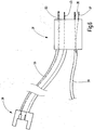
- Das Gehäuse 15 ist außerdem über ein Kabel 30 mit einem Stecker 31 verbunden, der zum Anschluss des Sondenapplikators 10 an ein speisendes Gerät dient. Dieses ist dazu eingerichtet, die Sonde 11 mit dem nötigen Betriebsmedium, beispielsweise elektrischer Spannung und/oder einem flüssigen oder gasförmigen Fluid oder auch Vakuum zu versorgen. Außerdem kann der Stecker 31 dazu eingerichtet sein, Steuersignale von dem Sondenapplikator 10, insbesondere von an diesem vorgesehenen Steuerelementen 32, 33, an das versorgende Gerät zu übertragen. Die Steuerelemente 32, 33 können beispielsweise elektrische Schalter sein, deren Schaltzustand über Leitungen 34, 35 (
Figur 5 ), die sich durch das Kabel 30 erstrecken, zu entsprechenden Pins 36, 37 an dem Stecker 31 gegeben werden. Beispielsweise kann der Schalter 32 den Stromfluss über eine Diode in einer Stromrichtung zwischen den beiden Leitungen 34, 35 freigeben, während der Schalter 33 den Stromfluss über eine andere anders herum gepolte Diode in Gegenrichtung zwischen den beiden Leitungen 34, 35 freigibt. Auf diese Weise kann an den beiden Pins 36, 37 unterschieden werden, ob kein Schalter, ein Schalter oder beide Schalter betätigt sind. Andere Verschaltungen sind möglich, z.B. können alle Schalter an eine gemeinsame Bezugspotentialleitung und eine individuelle Signalleitung angeschlossen sein. - Anstelle der elektrischen Leitungen 34, 35 können auch ein oder mehrere andere Signalleitungen, beispielsweise optische Wellenleiter oder dergleichen, vorgesehen sein, wobei wenigstens ein Steuerelement 32 und/oder 33 dann zum Beispiel die Reflexionseigenschaften am Ende eines solchen optischen Wellenleiters beeinflusst um eine Signalgabe zu bewirken.
- Der Stecker 31 enthält eine Anschlussvorrichtung 38 für die Sonde 11. Die Anschlussvorrichtung 38 kann beispielsweise eine in dem Stecker 31 ausgebildete Öffnung 39 sein, in die ein an dem proximalen Ende der Sonde 11 vorgesehener Sondenstecker 40 eingesteckt werden kann. Dieser dient zur Versorgung der Sonde 11 mit ihrem Betriebsmedium. Zum Beispiel kann der Sondenstecker 40, wie in
Figur 5 in einer ersten Variante dargestellt ist, einen elektrischen Kontakt 41 aufweisen, dem eine in der Öffnung 39 vorgesehen Kontaktbuchse 42 oder andere Kontaktmittel zugeordnet ist oder sind. Diese Kontaktbuchse 42 ist mit einem entsprechenden Pin 43 des Steckers 31 elektrisch verbunden. - Die Sonde 11 kann, wie insbesondere aus
Figur 1 und2 hervorgeht, über geeignete Klammern 44 bis 47 oder durch andre geeignete Mittel mit dem Kabel 30 verbunden sein. Die Sonde erstreckt sich dann, ausgehend von der Anschlussvorrichtung 38, durch das Gehäuse 15 und den Schaft 12 hindurch bis zu dem distalen Ende 20 des Schafts 12. WieFigur 3 erkennen lässt, kann in oder an dem Gehäuse 15 eine Feststelleinrichtung 48 vorgesehen sein, die manuell betätigbar ist, um eine axiale Bewegung der Sonde 11 wahlweise freizugeben oder zu sperren. Die Feststelleinrichtung 48 kann beispielsweise eine Klemmeinrichtung sein, zum Beispiel in Gestalt eines Exzenterklemmhebels 49, dem ein Widerlager 50 gegenüber liegt. Die Sonde 11 ist zwischen dem Widerlager 50 und dem Klemmhebel 49 angeordnet und kann durch Betätigung des Klemmhebels 49 entsprechend fixiert werden. - Der insoweit beschriebene Sondenapplikator 10 arbeitet wie folgt:
- Zur Verwendung wird eine Sonde 11 durch eine entsprechende Einführöffnung 51 (
Figur 3 ), die dem proximalen Ende 13 des Schafts 12 gegenüber liegt und in gerader Verlängerung desselben angeordnet ist, in das Gehäuse 15 ein- und durch dieses hindurch in das Lumen 17 eingeschoben. Die Sonde 11 wird dabei zunächst vorzugsweise so weit vorgeschoben, dass ihr distales Ende 18 aus dem Endabschnitt 20 herausragt oder kurz vor dessen Mündung steht. In dieser Position kann die Sonde 11 mit der Feststelleinrichtung 48 fixiert werden. Vor oder nach dieser Maßnahme wird der Sondenstecker 40 in die Anschlussvorrichtung 38 eingeführt und der Stecker 31 wird mit dem versorgenden Gerät verbunden. Gegebenenfalls wird an dem Gerät die gewünschte Betriebsart gewählt. Damit ist der Sondenapplikator 10 mit der eingefügten Sonde 11 betriebsbereit. - Der Schaft 12 kann mit seinem distalen Ende 16 durch eine Öffnung, zum Beispiel einen Schnitt, in einen Patienten eingeführt werden, wobei der Sondenapplikator 10 von dem Behandler an dem Griff 25 gehalten und mittels dessen positioniert wird. Falls gewünscht, kann der Behandler mittels der Betätigungseinrichtung 26 das distale Ende 16 des Schafts 12 abwinkeln, um das distale Ende 18 der Sonde 11 in eine gewünschte Winkellage zu bringen. Außerdem kann er den Schaft 12 insbesondere bei abgewinkeltem Ende um seine Längsachse drehen. Falls gewünscht, kann er außerdem die Klemmvorrichtung 48 lösen und die Sonde 11 weiter vorschieben oder zurückziehen. Mit den Steuerelementen 32, 33 kann er das speisende Gerät veranlassen, die Sonde 11 zu aktivieren oder zu deaktivieren. Beispielsweise kann er über die Steuerelemente 32, 33 Strom einschalten, Strom ausschalten oder verschiedene Moden zum Beispiel Spannungshöhen oder Spannungsformen (Kurvenformen, Crestfaktoren) auswählen und aktivieren sowie deaktivieren.
- Die Anschlussvorrichtung 38 ist nicht auf Versorgung elektrischer Sonden beschränkt. Sie kann zum Beispiel zusätzlich oder alternativ zu dem Kontaktmittel 32 einen Fluidanschluss 52 aufweisen, zum Beispiel in Form einer Fluidsteckbuchse. Diese kann über einen geeigneten Kanal mit einem Fluidsteckpin 53 verbunden sein, der vorzugsweise parallel zu dem Kontaktpins 36, 37, 43 von dem Stecker 31 weg ragt. Entsprechend kann eine Sonde 11a mit einem Fluidsteckpin 54 versehen sein, der dem Fluidanschluss 52 zugeordnet ist. Zusätzlich kann wiederum ein elektrischer Kontakt 41 vorgesehen sein. In diesem Fall können die Steuerelemente 32, 33 dazu dienen, die Fluidversorgung und die Stromversorgung der Sonde 11a voneinander unabhängig zu aktivieren oder zu deaktivieren.
- Wie aus
Figur 6 ersichtlich ist, muss die Anschlussvorrichtung 38 nicht zwingend unmittelbar an dem Stecker 31 ausgebildet sein. Es ist auch möglich, als Anschlussvorrichtung 38 eine gesonderte Buchsenanordnung vorzugsehen, die über eine Leitung 55 mit dem Stecker 31 verbunden ist. Weiter alternativ kann die Anschlussvorrichtung 38 an dem speisendem Gerät selbst vorgesehen sein. Ansonsten gilt die vorige Beschreibung entsprechend. - Erfindungsgemäß ist ein Sondenapplikator 10 vorgesehene, der zur Aufnahme flexibler Sonden 11, 11a dient, die für den endoskopischen Einsatz vorgesehen sind und mit dem Sondenapplikator für den laparoskopischen Einsatz zugänglich gemacht werden. Die Steuerung des die Sonden 11, 11a speisenden Geräts erfolgt über Steuerelemente 32, 33 des Sondenapplikators 10. Vorzugsweise erfolgt die Versorgung der Sonde 11, 11a über eine an dem Sondenapplikator 10 vorgesehene Anschlussvorrichtung 38.
Bezugszeichen: 10 Sondenapplikator 11 Sonde 12 Schaft 13 proximales Ende des Schafts 12 14 Schaftaufnahme 15 Gehäuse 16 distales Ende des Schafts 12 17 Lumen 18 distales Ende der Sonde 11 19 flexibler Abschnitt des Schafts 12 20 Endabschnitt des Schafts 12 21 Krümmungsachse 22 axial nachgiebiger Bereich 23 axial steifer Bereich 24 Abwinkeleinrichtung 25 Griff 26 Betätigungseinrichtung 27 Hebel 28 Kraftübertragungsmittel 29 Zugmittel 30 Kabel 31 Stecker 32, 33 Steuerelemente 34, 35 Leitungen 36, 37 Pins 38 Anschlussvorrichtung 39 Öffnung 40 Sondenstecker 41 elektrischer Kontakt 42 Kontaktmittel 43 Pin des Steckers 31 44 - 47 Klammern 48 Feststelleinrichtung 49 Exzenterklemmhebel 50 Widerlager 51 Einführöffnung 52 Fluidanschluss 53 Fluidsteckpin 54 Fluidsteckpin 55 Leitung
Claims (14)
- Sondenapplikator (10) zum laparoskopischen Einsatz von flexiblen Sonden (11, 11a),
mit einem Gehäuse (15), das einen Griff (25) zur manuellen Positionierung und Bewegung des Sondenapplikators (10) in Bezug auf einen Patienten aufweist,
mit einem Schaft (12), der ein längliches, steifes Rohr ist, das an einem proximalen Ende (13) mit einer an dem Gehäuse (15) vorgesehenen Schaftaufnahme (14) verbunden und an seinem distalen Ende (16) offen ist, mit wenigstens einem an dem Gehäuse (15) zur manuellen Betätigung zugänglich angeordneten Steuerelement (32, 33),
mit einem Kabel (30), das sich von dem Gehäuse (15) zu einem Stecker (31) mit wenigstens einem Steckverbinder (36) erstreckt und wenigstens eine Signalleitung (34) enthält, die das Steuerelement (32) mit dem Steckkontakt (36) verbindet,
mit einer an dem Gehäuse (15) vorgesehenen Sonden-Einführöffnung (51), die der Schaftaufnahme (14) gegenüberliegend angeordnet ist, und
mit einer Anschlussvorrichtung (38), die zum Anschluss einer Sonde (11, 11a) eingerichtet ist, um diese mit Betriebsmedium zu versorgen. - Sondenapplikator nach Anspruch 1, dadurch gekennzeichnet, dass der Schaft (12) eine Länge aufweist, die das Zwanzigfache, vorzugsweise das Fünfzig- bis Neunzigfache des Durchmessers des Schafts (12) übersteigt und vorzugsweise geringer als das 300-fache, weiter vorzugsweise geringer als das 150-fache des Durchmessers des Schafts (12) ist.
- Sondenapplikator nach einem der vorstehenden Ansprüche, dadurch gekennzeichnet, dass an dem distalen Ende (16) des Schafts (12) eine Abwinkelungseinrichtung (24) angeordnet ist, die mit einer an dem Gehäuse (15) angeordneten Betätigungseinrichtung (26) verbunden ist.
- Sondenapplikator nach Anspruch 3, dadurch gekennzeichnet, dass die Betätigungseinrichtung (26) ein an dem Griff (25) angeordneter Schwenkhebel (27) ist, der über ein Kraftübertragungsmittel (28) mit der Abwinkelungseinrichtung (24) verbunden ist.
- Sondenapplikator nach einem der vorstehenden Ansprüche, dass die Abwinkelungseinrichtung (24) einen flexiblen Abschnitt (19) aufweist, der von einer gestreckten Form in eine Bogenform überführbar ist.
- Sondenapplikator nach einem der vorstehenden Ansprüche, dadurch gekennzeichnet, dass die Abwinkelungseinrichtung (24) an ihrem distalen Ende einen steifen geraden Rohrabschnitt (20) trägt.
- Sondenapplikator nach einem der vorstehenden Ansprüche, dadurch gekennzeichnet, dass der Schaft (12) an dem Gehäuse (15) um eine Schaftlängsachse drehbar gehalten ist.
- Sondenapplikator nach einem der vorstehenden Ansprüche, dadurch gekennzeichnet, dass an der Sonden-Einführöffnung (51) eine Festelleinrichtung (48) zur axialen Fixierung einer sich durch die Sonden-Einführöffnung (51) erstreckenden Sonde (11, 11a) angeordnet ist.
- Sondenapplikator nach Anspruch 8, dadurch gekennzeichnet, dass die Feststelleinrichtung (48) eine manuell betätigbare Klemmeinrichtung (49) ist.
- Sondenapplikator nach einem der vorstehenden Ansprüche, dadurch gekennzeichnet, dass die Signalleitung (34) eine elektrische Leitung ist und dass der Steckverbinder ein elektrischer Steckkontakt (36) ist.
- Sondenapplikator nach einem der vorstehenden Ansprüche, dadurch gekennzeichnet, dass das Kabel (30) Verbindungsmittel (44 - 47) zur Aufnahme einer Sonde (11, 11a) trägt.
- Sondenapplikator nach einem der vorstehenden Ansprüche, dadurch gekennzeichnet, dass die Anschlussvorrichtung (38) an dem Stecker (31) angeordnet ist.
- Sondenapplikator nach einem der vorstehenden Ansprüche, dadurch gekennzeichnet, dass die Anschlussvorrichtung (38) wenigstens eine Fluidanschluss (52) umfasst.
- Sondenapplikator nach einem der vorstehenden Ansprüche, dadurch gekennzeichnet, dass die Anschlussvorrichtung (38) wenigstens einen elektrischen Anschluss (42) umfasst.
Priority Applications (8)
| Application Number | Priority Date | Filing Date | Title |
|---|---|---|---|
| PL17206694T PL3498203T3 (pl) | 2017-12-12 | 2017-12-12 | Aplikator sondy |
| EP17206694.6A EP3498203B1 (de) | 2017-12-12 | 2017-12-12 | Sondenapplikator |
| BR102018067342-4A BR102018067342B1 (pt) | 2017-12-12 | 2018-08-31 | Aplicador de sonda |
| RU2018142844A RU2761030C2 (ru) | 2017-12-12 | 2018-12-04 | Держатель зонда |
| JP2018229592A JP7186595B2 (ja) | 2017-12-12 | 2018-12-07 | プローブアプリケータ |
| CN201811493032.4A CN110013299B (zh) | 2017-12-12 | 2018-12-07 | 探针施加器 |
| KR1020180158768A KR102568445B1 (ko) | 2017-12-12 | 2018-12-11 | 프로브 애플리케이터 |
| US16/216,301 US11141217B2 (en) | 2017-12-12 | 2018-12-11 | Probe applicator |
Applications Claiming Priority (1)
| Application Number | Priority Date | Filing Date | Title |
|---|---|---|---|
| EP17206694.6A EP3498203B1 (de) | 2017-12-12 | 2017-12-12 | Sondenapplikator |
Publications (2)
| Publication Number | Publication Date |
|---|---|
| EP3498203A1 true EP3498203A1 (de) | 2019-06-19 |
| EP3498203B1 EP3498203B1 (de) | 2021-11-03 |
Family
ID=60673478
Family Applications (1)
| Application Number | Title | Priority Date | Filing Date |
|---|---|---|---|
| EP17206694.6A Active EP3498203B1 (de) | 2017-12-12 | 2017-12-12 | Sondenapplikator |
Country Status (8)
| Country | Link |
|---|---|
| US (1) | US11141217B2 (de) |
| EP (1) | EP3498203B1 (de) |
| JP (1) | JP7186595B2 (de) |
| KR (1) | KR102568445B1 (de) |
| CN (1) | CN110013299B (de) |
| BR (1) | BR102018067342B1 (de) |
| PL (1) | PL3498203T3 (de) |
| RU (1) | RU2761030C2 (de) |
Families Citing this family (5)
| Publication number | Priority date | Publication date | Assignee | Title |
|---|---|---|---|---|
| CA3145302A1 (en) * | 2019-07-09 | 2021-01-14 | Arrinex, Inc. | Devices and methods for treating ear, nose, and throat afflictions |
| CN110575603A (zh) * | 2019-10-14 | 2019-12-17 | 苏州法兰克曼医疗器械有限公司 | 一种具有可视功能的导丝输送装置 |
| US12279755B2 (en) | 2020-03-04 | 2025-04-22 | Anqing Medical Co., Ltd. | Rigid endoscope |
| US20210320445A1 (en) * | 2020-04-14 | 2021-10-14 | Instrument Manufacturing Company | Systems and Methods for Injecting Electrical Cables with a Fluid |
| CN111714201B (zh) * | 2020-06-10 | 2021-06-08 | 海杰亚(北京)医疗器械有限公司 | 一种用于人体肿瘤冷冻治疗的柔性探针组件 |
Citations (5)
| Publication number | Priority date | Publication date | Assignee | Title |
|---|---|---|---|---|
| US5314406A (en) | 1992-10-09 | 1994-05-24 | Symbiosis Corporation | Endoscopic electrosurgical suction-irrigation instrument |
| DE10354147A1 (de) * | 2003-11-19 | 2005-06-30 | Richard Wolf Gmbh | Medizinische Steckverbindungsvorrichtung mit einem Stecker und einer Kupplung |
| US20120253116A1 (en) * | 2011-03-29 | 2012-10-04 | Tyco Healthcare Group Lp | System and Method for Performing Surgical Procedures with a Modular Surgical System |
| US20140236147A1 (en) * | 2013-02-20 | 2014-08-21 | Sven Schneider | Endoscopic instrument, and shaft for an endoscopic instrument |
| CN204147118U (zh) * | 2014-10-20 | 2015-02-11 | 张占学 | 一种握持式钩吸消融电极 |
Family Cites Families (9)
| Publication number | Priority date | Publication date | Assignee | Title |
|---|---|---|---|---|
| US6761698B2 (en) * | 2000-07-28 | 2004-07-13 | Olympus Corporation | Ultrasonic operation system |
| DE102006008739A1 (de) * | 2006-02-24 | 2007-09-13 | Erbe Elektromedizin Gmbh | Sondenmanipulator |
| WO2008057805A1 (en) | 2006-11-01 | 2008-05-15 | Bovie Medical Corporation | Bipolar ablation probe having porous electrodes for delivering electrically conductive fluid |
| CA2746948C (en) * | 2010-07-21 | 2019-01-15 | Diros Technology Inc. | Advanced multi-purpose catheter probes for diagnostic and therapeutic procedures |
| RU2460551C1 (ru) * | 2011-04-27 | 2012-09-10 | Сергей Александрович Габриэль | Катетер управляемый для эндоскопических вмешательств |
| US9011429B2 (en) * | 2012-06-07 | 2015-04-21 | Smith & Nephew, Inc. | Flexible probe with adjustable tip |
| CN106659375A (zh) * | 2014-05-13 | 2017-05-10 | Vycor医学有限责任公司 | 用于手术导引器的引导系统安装件 |
| EP3250141B1 (de) * | 2015-01-28 | 2023-10-11 | Apyx Medical Corporation | Elektrochirurgische kaltplasmavorrichtung mit applikator mit gebogener spitze |
| WO2017192897A1 (en) * | 2016-05-06 | 2017-11-09 | Cardioscout Solutions, Inc. | Access devices and methods for treatment of medical conditions and delivery of injectables |
-
2017
- 2017-12-12 PL PL17206694T patent/PL3498203T3/pl unknown
- 2017-12-12 EP EP17206694.6A patent/EP3498203B1/de active Active
-
2018
- 2018-08-31 BR BR102018067342-4A patent/BR102018067342B1/pt active IP Right Grant
- 2018-12-04 RU RU2018142844A patent/RU2761030C2/ru active
- 2018-12-07 JP JP2018229592A patent/JP7186595B2/ja active Active
- 2018-12-07 CN CN201811493032.4A patent/CN110013299B/zh active Active
- 2018-12-11 US US16/216,301 patent/US11141217B2/en active Active
- 2018-12-11 KR KR1020180158768A patent/KR102568445B1/ko active Active
Patent Citations (5)
| Publication number | Priority date | Publication date | Assignee | Title |
|---|---|---|---|---|
| US5314406A (en) | 1992-10-09 | 1994-05-24 | Symbiosis Corporation | Endoscopic electrosurgical suction-irrigation instrument |
| DE10354147A1 (de) * | 2003-11-19 | 2005-06-30 | Richard Wolf Gmbh | Medizinische Steckverbindungsvorrichtung mit einem Stecker und einer Kupplung |
| US20120253116A1 (en) * | 2011-03-29 | 2012-10-04 | Tyco Healthcare Group Lp | System and Method for Performing Surgical Procedures with a Modular Surgical System |
| US20140236147A1 (en) * | 2013-02-20 | 2014-08-21 | Sven Schneider | Endoscopic instrument, and shaft for an endoscopic instrument |
| CN204147118U (zh) * | 2014-10-20 | 2015-02-11 | 张占学 | 一种握持式钩吸消融电极 |
Also Published As
| Publication number | Publication date |
|---|---|
| KR20190070293A (ko) | 2019-06-20 |
| BR102018067342B1 (pt) | 2022-05-03 |
| JP2019103804A (ja) | 2019-06-27 |
| BR102018067342A2 (pt) | 2019-06-25 |
| US11141217B2 (en) | 2021-10-12 |
| JP7186595B2 (ja) | 2022-12-09 |
| PL3498203T3 (pl) | 2022-02-07 |
| RU2018142844A3 (de) | 2021-05-31 |
| EP3498203B1 (de) | 2021-11-03 |
| RU2761030C2 (ru) | 2021-12-02 |
| CN110013299B (zh) | 2022-09-09 |
| RU2018142844A (ru) | 2020-06-04 |
| CN110013299A (zh) | 2019-07-16 |
| KR102568445B1 (ko) | 2023-08-22 |
| US20190175261A1 (en) | 2019-06-13 |
Similar Documents
| Publication | Publication Date | Title |
|---|---|---|
| EP3498203B1 (de) | Sondenapplikator | |
| EP2676597B1 (de) | Endoskophülle, Endoskopanordnung und Verfahren zum Bereitstellen einer Endoskopanordnung | |
| EP1680037B1 (de) | Medizinisches instrument mit endoskop | |
| EP1767139A1 (de) | Beleuchtungssystem für endoskopische Untersuchungen | |
| DE102008015418A1 (de) | Medizinisches Instrument | |
| DE3633527A1 (de) | Instrumente zur zertruemmerung von konkrementen in hohlorganen | |
| DE102010040415B4 (de) | Instrument für einen Manipulatorarm eines Endoskopieroboters | |
| WO2010105649A1 (de) | Rohrförmiger schaft eines chirurgischen instruments und verwendung desselben | |
| DE102017120341A1 (de) | Medizinisches Instrument zum Abtragen von Gewebe mittels einer HF-Elektrode mit der Funktion einer kontrollierten distalen Winkelausrichtung | |
| EP2438844A2 (de) | Gelenkabschnitt eines Schafts für ein endoskopisches Instrument | |
| WO2005104966A1 (de) | Chirurgisches instrumentensystem | |
| WO2017036479A1 (de) | Schaftinstrument und insbesondere medizinisch-endoskopisches schaftinstrument | |
| DE102014205006A1 (de) | Endoskopisches Schaftinstrument | |
| EP4046583B1 (de) | Elektrochirurgisches handgerät und kontaktkörper für elektrochirurgisches handgerät | |
| DE10045036C1 (de) | Therapeutisches Endoskop | |
| DE202006017173U1 (de) | Uretero-Renoskop | |
| DE102010028590A1 (de) | Rohrförmiger Schaft eines chirurgischen Instruments | |
| EP2848189A1 (de) | Endoskopisches System | |
| DE102009022867B4 (de) | Minimalinvasives Medizininstrument | |
| DE202007000428U1 (de) | Elektrochirurgisches Verbindungsglied und elekrochirurgisches Instrument | |
| WO2003082394A1 (de) | Biopsieinstrument | |
| DE102007001751A1 (de) | Elektrochirurgisches Verbindungsglied und elektrochirurgisches Instrument | |
| EP3203897A2 (de) | Handgriff eines endoskops | |
| EP3151723A1 (de) | Endoskop mit mehreren proximalen arbeitskanal-anschlüssen | |
| DE69837853T2 (de) | Ausrichtbare endoskopische chirurgische vorrichtung |
Legal Events
| Date | Code | Title | Description |
|---|---|---|---|
| PUAI | Public reference made under article 153(3) epc to a published international application that has entered the european phase |
Free format text: ORIGINAL CODE: 0009012 |
|
| STAA | Information on the status of an ep patent application or granted ep patent |
Free format text: STATUS: THE APPLICATION HAS BEEN PUBLISHED |
|
| AK | Designated contracting states |
Kind code of ref document: A1 Designated state(s): AL AT BE BG CH CY CZ DE DK EE ES FI FR GB GR HR HU IE IS IT LI LT LU LV MC MK MT NL NO PL PT RO RS SE SI SK SM TR |
|
| AX | Request for extension of the european patent |
Extension state: BA ME |
|
| STAA | Information on the status of an ep patent application or granted ep patent |
Free format text: STATUS: REQUEST FOR EXAMINATION WAS MADE |
|
| 17P | Request for examination filed |
Effective date: 20191024 |
|
| RBV | Designated contracting states (corrected) |
Designated state(s): AL AT BE BG CH CY CZ DE DK EE ES FI FR GB GR HR HU IE IS IT LI LT LU LV MC MK MT NL NO PL PT RO RS SE SI SK SM TR |
|
| GRAP | Despatch of communication of intention to grant a patent |
Free format text: ORIGINAL CODE: EPIDOSNIGR1 |
|
| STAA | Information on the status of an ep patent application or granted ep patent |
Free format text: STATUS: GRANT OF PATENT IS INTENDED |
|
| INTG | Intention to grant announced |
Effective date: 20210226 |
|
| GRAJ | Information related to disapproval of communication of intention to grant by the applicant or resumption of examination proceedings by the epo deleted |
Free format text: ORIGINAL CODE: EPIDOSDIGR1 |
|
| STAA | Information on the status of an ep patent application or granted ep patent |
Free format text: STATUS: REQUEST FOR EXAMINATION WAS MADE |
|
| GRAP | Despatch of communication of intention to grant a patent |
Free format text: ORIGINAL CODE: EPIDOSNIGR1 |
|
| STAA | Information on the status of an ep patent application or granted ep patent |
Free format text: STATUS: GRANT OF PATENT IS INTENDED |
|
| INTC | Intention to grant announced (deleted) | ||
| GRAJ | Information related to disapproval of communication of intention to grant by the applicant or resumption of examination proceedings by the epo deleted |
Free format text: ORIGINAL CODE: EPIDOSDIGR1 |
|
| STAA | Information on the status of an ep patent application or granted ep patent |
Free format text: STATUS: REQUEST FOR EXAMINATION WAS MADE |
|
| INTG | Intention to grant announced |
Effective date: 20210624 |
|
| INTC | Intention to grant announced (deleted) | ||
| GRAP | Despatch of communication of intention to grant a patent |
Free format text: ORIGINAL CODE: EPIDOSNIGR1 |
|
| STAA | Information on the status of an ep patent application or granted ep patent |
Free format text: STATUS: GRANT OF PATENT IS INTENDED |
|
| GRAS | Grant fee paid |
Free format text: ORIGINAL CODE: EPIDOSNIGR3 |
|
| INTG | Intention to grant announced |
Effective date: 20210903 |
|
| GRAA | (expected) grant |
Free format text: ORIGINAL CODE: 0009210 |
|
| STAA | Information on the status of an ep patent application or granted ep patent |
Free format text: STATUS: THE PATENT HAS BEEN GRANTED |
|
| AK | Designated contracting states |
Kind code of ref document: B1 Designated state(s): AL AT BE BG CH CY CZ DE DK EE ES FI FR GB GR HR HU IE IS IT LI LT LU LV MC MK MT NL NO PL PT RO RS SE SI SK SM TR |
|
| REG | Reference to a national code |
Ref country code: GB Ref legal event code: FG4D Free format text: NOT ENGLISH |
|
| REG | Reference to a national code |
Ref country code: AT Ref legal event code: REF Ref document number: 1443284 Country of ref document: AT Kind code of ref document: T Effective date: 20211115 Ref country code: CH Ref legal event code: EP |
|
| REG | Reference to a national code |
Ref country code: DE Ref legal event code: R096 Ref document number: 502017011897 Country of ref document: DE |
|
| REG | Reference to a national code |
Ref country code: IE Ref legal event code: FG4D Free format text: LANGUAGE OF EP DOCUMENT: GERMAN |
|
| REG | Reference to a national code |
Ref country code: LT Ref legal event code: MG9D |
|
| REG | Reference to a national code |
Ref country code: NL Ref legal event code: MP Effective date: 20211103 |
|
| PG25 | Lapsed in a contracting state [announced via postgrant information from national office to epo] |
Ref country code: RS Free format text: LAPSE BECAUSE OF FAILURE TO SUBMIT A TRANSLATION OF THE DESCRIPTION OR TO PAY THE FEE WITHIN THE PRESCRIBED TIME-LIMIT Effective date: 20211103 Ref country code: LT Free format text: LAPSE BECAUSE OF FAILURE TO SUBMIT A TRANSLATION OF THE DESCRIPTION OR TO PAY THE FEE WITHIN THE PRESCRIBED TIME-LIMIT Effective date: 20211103 Ref country code: FI Free format text: LAPSE BECAUSE OF FAILURE TO SUBMIT A TRANSLATION OF THE DESCRIPTION OR TO PAY THE FEE WITHIN THE PRESCRIBED TIME-LIMIT Effective date: 20211103 Ref country code: BG Free format text: LAPSE BECAUSE OF FAILURE TO SUBMIT A TRANSLATION OF THE DESCRIPTION OR TO PAY THE FEE WITHIN THE PRESCRIBED TIME-LIMIT Effective date: 20220203 |
|
| PG25 | Lapsed in a contracting state [announced via postgrant information from national office to epo] |
Ref country code: IS Free format text: LAPSE BECAUSE OF FAILURE TO SUBMIT A TRANSLATION OF THE DESCRIPTION OR TO PAY THE FEE WITHIN THE PRESCRIBED TIME-LIMIT Effective date: 20220303 Ref country code: SE Free format text: LAPSE BECAUSE OF FAILURE TO SUBMIT A TRANSLATION OF THE DESCRIPTION OR TO PAY THE FEE WITHIN THE PRESCRIBED TIME-LIMIT Effective date: 20211103 Ref country code: PT Free format text: LAPSE BECAUSE OF FAILURE TO SUBMIT A TRANSLATION OF THE DESCRIPTION OR TO PAY THE FEE WITHIN THE PRESCRIBED TIME-LIMIT Effective date: 20220303 Ref country code: NO Free format text: LAPSE BECAUSE OF FAILURE TO SUBMIT A TRANSLATION OF THE DESCRIPTION OR TO PAY THE FEE WITHIN THE PRESCRIBED TIME-LIMIT Effective date: 20220203 Ref country code: NL Free format text: LAPSE BECAUSE OF FAILURE TO SUBMIT A TRANSLATION OF THE DESCRIPTION OR TO PAY THE FEE WITHIN THE PRESCRIBED TIME-LIMIT Effective date: 20211103 Ref country code: LV Free format text: LAPSE BECAUSE OF FAILURE TO SUBMIT A TRANSLATION OF THE DESCRIPTION OR TO PAY THE FEE WITHIN THE PRESCRIBED TIME-LIMIT Effective date: 20211103 Ref country code: HR Free format text: LAPSE BECAUSE OF FAILURE TO SUBMIT A TRANSLATION OF THE DESCRIPTION OR TO PAY THE FEE WITHIN THE PRESCRIBED TIME-LIMIT Effective date: 20211103 Ref country code: GR Free format text: LAPSE BECAUSE OF FAILURE TO SUBMIT A TRANSLATION OF THE DESCRIPTION OR TO PAY THE FEE WITHIN THE PRESCRIBED TIME-LIMIT Effective date: 20220204 Ref country code: ES Free format text: LAPSE BECAUSE OF FAILURE TO SUBMIT A TRANSLATION OF THE DESCRIPTION OR TO PAY THE FEE WITHIN THE PRESCRIBED TIME-LIMIT Effective date: 20211103 |
|
| PG25 | Lapsed in a contracting state [announced via postgrant information from national office to epo] |
Ref country code: SM Free format text: LAPSE BECAUSE OF FAILURE TO SUBMIT A TRANSLATION OF THE DESCRIPTION OR TO PAY THE FEE WITHIN THE PRESCRIBED TIME-LIMIT Effective date: 20211103 Ref country code: SK Free format text: LAPSE BECAUSE OF FAILURE TO SUBMIT A TRANSLATION OF THE DESCRIPTION OR TO PAY THE FEE WITHIN THE PRESCRIBED TIME-LIMIT Effective date: 20211103 Ref country code: RO Free format text: LAPSE BECAUSE OF FAILURE TO SUBMIT A TRANSLATION OF THE DESCRIPTION OR TO PAY THE FEE WITHIN THE PRESCRIBED TIME-LIMIT Effective date: 20211103 Ref country code: EE Free format text: LAPSE BECAUSE OF FAILURE TO SUBMIT A TRANSLATION OF THE DESCRIPTION OR TO PAY THE FEE WITHIN THE PRESCRIBED TIME-LIMIT Effective date: 20211103 Ref country code: DK Free format text: LAPSE BECAUSE OF FAILURE TO SUBMIT A TRANSLATION OF THE DESCRIPTION OR TO PAY THE FEE WITHIN THE PRESCRIBED TIME-LIMIT Effective date: 20211103 Ref country code: CZ Free format text: LAPSE BECAUSE OF FAILURE TO SUBMIT A TRANSLATION OF THE DESCRIPTION OR TO PAY THE FEE WITHIN THE PRESCRIBED TIME-LIMIT Effective date: 20211103 |
|
| REG | Reference to a national code |
Ref country code: CH Ref legal event code: PL |
|
| REG | Reference to a national code |
Ref country code: DE Ref legal event code: R097 Ref document number: 502017011897 Country of ref document: DE |
|
| PG25 | Lapsed in a contracting state [announced via postgrant information from national office to epo] |
Ref country code: MC Free format text: LAPSE BECAUSE OF FAILURE TO SUBMIT A TRANSLATION OF THE DESCRIPTION OR TO PAY THE FEE WITHIN THE PRESCRIBED TIME-LIMIT Effective date: 20211103 |
|
| PLBE | No opposition filed within time limit |
Free format text: ORIGINAL CODE: 0009261 |
|
| STAA | Information on the status of an ep patent application or granted ep patent |
Free format text: STATUS: NO OPPOSITION FILED WITHIN TIME LIMIT |
|
| REG | Reference to a national code |
Ref country code: BE Ref legal event code: MM Effective date: 20211231 |
|
| 26N | No opposition filed |
Effective date: 20220804 |
|
| PG25 | Lapsed in a contracting state [announced via postgrant information from national office to epo] |
Ref country code: LU Free format text: LAPSE BECAUSE OF NON-PAYMENT OF DUE FEES Effective date: 20211212 Ref country code: IE Free format text: LAPSE BECAUSE OF NON-PAYMENT OF DUE FEES Effective date: 20211212 Ref country code: AL Free format text: LAPSE BECAUSE OF FAILURE TO SUBMIT A TRANSLATION OF THE DESCRIPTION OR TO PAY THE FEE WITHIN THE PRESCRIBED TIME-LIMIT Effective date: 20211103 |
|
| PG25 | Lapsed in a contracting state [announced via postgrant information from national office to epo] |
Ref country code: SI Free format text: LAPSE BECAUSE OF FAILURE TO SUBMIT A TRANSLATION OF THE DESCRIPTION OR TO PAY THE FEE WITHIN THE PRESCRIBED TIME-LIMIT Effective date: 20211103 Ref country code: BE Free format text: LAPSE BECAUSE OF NON-PAYMENT OF DUE FEES Effective date: 20211231 |
|
| PG25 | Lapsed in a contracting state [announced via postgrant information from national office to epo] |
Ref country code: LI Free format text: LAPSE BECAUSE OF NON-PAYMENT OF DUE FEES Effective date: 20211231 Ref country code: CH Free format text: LAPSE BECAUSE OF NON-PAYMENT OF DUE FEES Effective date: 20211231 |
|
| PG25 | Lapsed in a contracting state [announced via postgrant information from national office to epo] |
Ref country code: CY Free format text: LAPSE BECAUSE OF FAILURE TO SUBMIT A TRANSLATION OF THE DESCRIPTION OR TO PAY THE FEE WITHIN THE PRESCRIBED TIME-LIMIT Effective date: 20211103 |
|
| PG25 | Lapsed in a contracting state [announced via postgrant information from national office to epo] |
Ref country code: HU Free format text: LAPSE BECAUSE OF FAILURE TO SUBMIT A TRANSLATION OF THE DESCRIPTION OR TO PAY THE FEE WITHIN THE PRESCRIBED TIME-LIMIT; INVALID AB INITIO Effective date: 20171212 |
|
| REG | Reference to a national code |
Ref country code: AT Ref legal event code: MM01 Ref document number: 1443284 Country of ref document: AT Kind code of ref document: T Effective date: 20221212 |
|
| PG25 | Lapsed in a contracting state [announced via postgrant information from national office to epo] |
Ref country code: AT Free format text: LAPSE BECAUSE OF NON-PAYMENT OF DUE FEES Effective date: 20221212 |
|
| PG25 | Lapsed in a contracting state [announced via postgrant information from national office to epo] |
Ref country code: MK Free format text: LAPSE BECAUSE OF FAILURE TO SUBMIT A TRANSLATION OF THE DESCRIPTION OR TO PAY THE FEE WITHIN THE PRESCRIBED TIME-LIMIT Effective date: 20211103 Ref country code: AT Free format text: LAPSE BECAUSE OF NON-PAYMENT OF DUE FEES Effective date: 20221212 |
|
| PG25 | Lapsed in a contracting state [announced via postgrant information from national office to epo] |
Ref country code: TR Free format text: LAPSE BECAUSE OF FAILURE TO SUBMIT A TRANSLATION OF THE DESCRIPTION OR TO PAY THE FEE WITHIN THE PRESCRIBED TIME-LIMIT Effective date: 20211103 |
|
| PG25 | Lapsed in a contracting state [announced via postgrant information from national office to epo] |
Ref country code: MT Free format text: LAPSE BECAUSE OF FAILURE TO SUBMIT A TRANSLATION OF THE DESCRIPTION OR TO PAY THE FEE WITHIN THE PRESCRIBED TIME-LIMIT Effective date: 20211103 |
|
| PGFP | Annual fee paid to national office [announced via postgrant information from national office to epo] |
Ref country code: PL Payment date: 20241118 Year of fee payment: 8 |
|
| PGFP | Annual fee paid to national office [announced via postgrant information from national office to epo] |
Ref country code: GB Payment date: 20241218 Year of fee payment: 8 |
|
| PGFP | Annual fee paid to national office [announced via postgrant information from national office to epo] |
Ref country code: FR Payment date: 20241227 Year of fee payment: 8 |
|
| PGFP | Annual fee paid to national office [announced via postgrant information from national office to epo] |
Ref country code: IT Payment date: 20241220 Year of fee payment: 8 |
|
| PGFP | Annual fee paid to national office [announced via postgrant information from national office to epo] |
Ref country code: DE Payment date: 20241227 Year of fee payment: 8 |
|
| PGFP | Annual fee paid to national office [announced via postgrant information from national office to epo] |
Ref country code: AT Payment date: 20260410 Year of fee payment: 5 |