EP3495626A1 - Hebelanbindung und zugehörige strömungsmaschine - Google Patents
Hebelanbindung und zugehörige strömungsmaschine Download PDFInfo
- Publication number
- EP3495626A1 EP3495626A1 EP18209948.1A EP18209948A EP3495626A1 EP 3495626 A1 EP3495626 A1 EP 3495626A1 EP 18209948 A EP18209948 A EP 18209948A EP 3495626 A1 EP3495626 A1 EP 3495626A1
- Authority
- EP
- European Patent Office
- Prior art keywords
- lever
- clamping sleeve
- connection
- blade shank
- vane
- Prior art date
- Legal status (The legal status is an assumption and is not a legal conclusion. Google has not performed a legal analysis and makes no representation as to the accuracy of the status listed.)
- Granted
Links
Images




Classifications
-
- F—MECHANICAL ENGINEERING; LIGHTING; HEATING; WEAPONS; BLASTING
- F01—MACHINES OR ENGINES IN GENERAL; ENGINE PLANTS IN GENERAL; STEAM ENGINES
- F01D—NON-POSITIVE DISPLACEMENT MACHINES OR ENGINES, e.g. STEAM TURBINES
- F01D17/00—Regulating or controlling by varying flow
- F01D17/10—Final actuators
- F01D17/12—Final actuators arranged in stator parts
- F01D17/14—Final actuators arranged in stator parts varying effective cross-sectional area of nozzles or guide conduits
- F01D17/16—Final actuators arranged in stator parts varying effective cross-sectional area of nozzles or guide conduits by means of nozzle vanes
- F01D17/162—Final actuators arranged in stator parts varying effective cross-sectional area of nozzles or guide conduits by means of nozzle vanes for axial flow, i.e. the vanes turning around axes which are essentially perpendicular to the rotor centre line
-
- F—MECHANICAL ENGINEERING; LIGHTING; HEATING; WEAPONS; BLASTING
- F01—MACHINES OR ENGINES IN GENERAL; ENGINE PLANTS IN GENERAL; STEAM ENGINES
- F01D—NON-POSITIVE DISPLACEMENT MACHINES OR ENGINES, e.g. STEAM TURBINES
- F01D9/00—Stators
- F01D9/02—Nozzles; Nozzle boxes; Stator blades; Guide conduits, e.g. individual nozzles
- F01D9/04—Nozzles; Nozzle boxes; Stator blades; Guide conduits, e.g. individual nozzles forming ring or sector
- F01D9/041—Nozzles; Nozzle boxes; Stator blades; Guide conduits, e.g. individual nozzles forming ring or sector using blades
-
- F—MECHANICAL ENGINEERING; LIGHTING; HEATING; WEAPONS; BLASTING
- F01—MACHINES OR ENGINES IN GENERAL; ENGINE PLANTS IN GENERAL; STEAM ENGINES
- F01D—NON-POSITIVE DISPLACEMENT MACHINES OR ENGINES, e.g. STEAM TURBINES
- F01D19/00—Starting of machines or engines; Regulating, controlling, or safety means in connection therewith
-
- F—MECHANICAL ENGINEERING; LIGHTING; HEATING; WEAPONS; BLASTING
- F04—POSITIVE - DISPLACEMENT MACHINES FOR LIQUIDS; PUMPS FOR LIQUIDS OR ELASTIC FLUIDS
- F04D—NON-POSITIVE-DISPLACEMENT PUMPS
- F04D29/00—Details, component parts, or accessories
- F04D29/40—Casings; Connections of working fluid
- F04D29/52—Casings; Connections of working fluid for axial pumps
- F04D29/54—Fluid-guiding means, e.g. diffusers
- F04D29/56—Fluid-guiding means, e.g. diffusers adjustable
- F04D29/563—Fluid-guiding means, e.g. diffusers adjustable specially adapted for elastic fluid pumps
-
- F—MECHANICAL ENGINEERING; LIGHTING; HEATING; WEAPONS; BLASTING
- F05—INDEXING SCHEMES RELATING TO ENGINES OR PUMPS IN VARIOUS SUBCLASSES OF CLASSES F01-F04
- F05D—INDEXING SCHEME FOR ASPECTS RELATING TO NON-POSITIVE-DISPLACEMENT MACHINES OR ENGINES, GAS-TURBINES OR JET-PROPULSION PLANTS
- F05D2220/00—Application
- F05D2220/30—Application in turbines
- F05D2220/32—Application in turbines in gas turbines
- F05D2220/321—Application in turbines in gas turbines for a special turbine stage
- F05D2220/3216—Application in turbines in gas turbines for a special turbine stage for a special compressor stage
- F05D2220/3217—Application in turbines in gas turbines for a special turbine stage for a special compressor stage for the first stage of a compressor or a low pressure compressor
-
- F—MECHANICAL ENGINEERING; LIGHTING; HEATING; WEAPONS; BLASTING
- F05—INDEXING SCHEMES RELATING TO ENGINES OR PUMPS IN VARIOUS SUBCLASSES OF CLASSES F01-F04
- F05D—INDEXING SCHEME FOR ASPECTS RELATING TO NON-POSITIVE-DISPLACEMENT MACHINES OR ENGINES, GAS-TURBINES OR JET-PROPULSION PLANTS
- F05D2220/00—Application
- F05D2220/30—Application in turbines
- F05D2220/32—Application in turbines in gas turbines
- F05D2220/321—Application in turbines in gas turbines for a special turbine stage
- F05D2220/3216—Application in turbines in gas turbines for a special turbine stage for a special compressor stage
- F05D2220/3219—Application in turbines in gas turbines for a special turbine stage for a special compressor stage for the last stage of a compressor or a high pressure compressor
-
- F—MECHANICAL ENGINEERING; LIGHTING; HEATING; WEAPONS; BLASTING
- F05—INDEXING SCHEMES RELATING TO ENGINES OR PUMPS IN VARIOUS SUBCLASSES OF CLASSES F01-F04
- F05D—INDEXING SCHEME FOR ASPECTS RELATING TO NON-POSITIVE-DISPLACEMENT MACHINES OR ENGINES, GAS-TURBINES OR JET-PROPULSION PLANTS
- F05D2220/00—Application
- F05D2220/30—Application in turbines
- F05D2220/32—Application in turbines in gas turbines
- F05D2220/323—Application in turbines in gas turbines for aircraft propulsion, e.g. jet engines
-
- F—MECHANICAL ENGINEERING; LIGHTING; HEATING; WEAPONS; BLASTING
- F05—INDEXING SCHEMES RELATING TO ENGINES OR PUMPS IN VARIOUS SUBCLASSES OF CLASSES F01-F04
- F05D—INDEXING SCHEME FOR ASPECTS RELATING TO NON-POSITIVE-DISPLACEMENT MACHINES OR ENGINES, GAS-TURBINES OR JET-PROPULSION PLANTS
- F05D2230/00—Manufacture
- F05D2230/60—Assembly methods
-
- F—MECHANICAL ENGINEERING; LIGHTING; HEATING; WEAPONS; BLASTING
- F05—INDEXING SCHEMES RELATING TO ENGINES OR PUMPS IN VARIOUS SUBCLASSES OF CLASSES F01-F04
- F05D—INDEXING SCHEME FOR ASPECTS RELATING TO NON-POSITIVE-DISPLACEMENT MACHINES OR ENGINES, GAS-TURBINES OR JET-PROPULSION PLANTS
- F05D2240/00—Components
- F05D2240/10—Stators
- F05D2240/12—Fluid guiding means, e.g. vanes
-
- F—MECHANICAL ENGINEERING; LIGHTING; HEATING; WEAPONS; BLASTING
- F05—INDEXING SCHEMES RELATING TO ENGINES OR PUMPS IN VARIOUS SUBCLASSES OF CLASSES F01-F04
- F05D—INDEXING SCHEME FOR ASPECTS RELATING TO NON-POSITIVE-DISPLACEMENT MACHINES OR ENGINES, GAS-TURBINES OR JET-PROPULSION PLANTS
- F05D2250/00—Geometry
- F05D2250/10—Two-dimensional
- F05D2250/13—Two-dimensional trapezoidal
- F05D2250/131—Two-dimensional trapezoidal polygonal
-
- F—MECHANICAL ENGINEERING; LIGHTING; HEATING; WEAPONS; BLASTING
- F05—INDEXING SCHEMES RELATING TO ENGINES OR PUMPS IN VARIOUS SUBCLASSES OF CLASSES F01-F04
- F05D—INDEXING SCHEME FOR ASPECTS RELATING TO NON-POSITIVE-DISPLACEMENT MACHINES OR ENGINES, GAS-TURBINES OR JET-PROPULSION PLANTS
- F05D2260/00—Function
- F05D2260/30—Retaining components in desired mutual position
- F05D2260/36—Retaining components in desired mutual position by a form fit connection, e.g. by interlocking
-
- F—MECHANICAL ENGINEERING; LIGHTING; HEATING; WEAPONS; BLASTING
- F05—INDEXING SCHEMES RELATING TO ENGINES OR PUMPS IN VARIOUS SUBCLASSES OF CLASSES F01-F04
- F05D—INDEXING SCHEME FOR ASPECTS RELATING TO NON-POSITIVE-DISPLACEMENT MACHINES OR ENGINES, GAS-TURBINES OR JET-PROPULSION PLANTS
- F05D2260/00—Function
- F05D2260/30—Retaining components in desired mutual position
- F05D2260/37—Retaining components in desired mutual position by a press fit connection
-
- F—MECHANICAL ENGINEERING; LIGHTING; HEATING; WEAPONS; BLASTING
- F05—INDEXING SCHEMES RELATING TO ENGINES OR PUMPS IN VARIOUS SUBCLASSES OF CLASSES F01-F04
- F05D—INDEXING SCHEME FOR ASPECTS RELATING TO NON-POSITIVE-DISPLACEMENT MACHINES OR ENGINES, GAS-TURBINES OR JET-PROPULSION PLANTS
- F05D2260/00—Function
- F05D2260/85—Starting
Definitions
- the invention relates first of all to a lever connection for the non-rotatable connection of a guide vane to a lever of a vane adjustment of a turbomachine, wherein the vane has a vane shaft extending along a vertical axis.
- the invention has a turbomachine with a plurality of lever connections for producing a rotationally fixed coupling of the guide vanes to a vane adjustment.
- Compressors in axial flow machines usually include a vane adjustment in the area of the front compressor stages or in the high-pressure compressor. Due to the vane adjustment, the guide vanes of the relevant guide vane row are adjusted speed-dependent about their vertical axis, so that an absolute Leitradabströmwinkel is changeable. As a result, a stall during startup of the turbomachine or at low speeds can be prevented. A step load is reduced. Alternatively, a stall could be achieved by adjusting the blades of the compressor stages, but this is technically much more complex, so that the adjustment of the vanes has prevailed.
- the adjustment of the guide vanes of a row of vanes is conventionally carried out mechanically by actuation of an actuator.
- the actuator usually acts via an adjusting ring and each by means of a lever on the vanes.
- the adjusting ring is arranged outside the turbomachine and usually positioned downstream and coaxial with the row of guide vanes as viewed in the flow direction. It is rotatable in the circumferential direction and displaceable in the axial direction of the turbomachine.
- the adjusting rings are actuated at the same time via a control lever of the actuator which is mounted rotatably on the compressor housing and which extends in the axial direction of the turbomachine and is in each case connected to the adjusting rings.
- the lever In known vane adjustments, the lever is inserted in the radial direction of the turbomachine onto a vane shaft extending in the vertical direction of the vane. Thereafter, the lever on a small-area contact area of the blade shank positively fixed and secured by a screw. The screwing can be done by an internal thread or by an external thread.
- This type of lever connection requires a sufficiently thick blade shank for the design of the contact surfaces. Since the positive connection is realized only at the end and with relatively small contact surfaces, among other things locally higher mechanical stresses can arise.
- the object of the invention is to provide a lever connection of a vane adjustment of a turbomachine for producing a rotationally fixed connection between a vane and a lever, which avoids the disadvantages mentioned above.
- a lever connection for non-rotatably connecting a guide vane with a lever of a vane adjustment of a turbomachine
- the guide vane has a blade axis extending along a vertical axis
- the lever is integrally formed on a radially outer end of the vane shank partially coaxially enclosing, substantially hollow cylindrical clamping sleeve and the blade shank and the clamping sleeve are coupled via a longitudinally form-fitting connection or an end-face positive connection, and the blade shank can be braced with the clamping sleeve along the vertical axis by means of a fastening element, in particular a threaded nut.
- the longitudinal-side positive connection also extends parallel to the vertical axis of the blade shank.
- the threaded nut is usually self-locking. Instead of a threaded nut, for example, a threaded bolt can be used as a tensioning or fastening element.
- the clamping sleeve has a collar for securing the radial position of the guide vane in a housing of the turbomachine, wherein there is a defined gap between the collar and the housing.
- a smooth storage is given.
- a cylindrical bearing portion for pivotally mounting the guide vane in the housing.
- At least one bushing is arranged between a bore of the housing and the bearing portion of the clamping sleeve.
- the at least one at least approximately hollow cylindrical bush and the housing of the turbomachine in this area a low-wear storage possible.
- tolerance compensation can be realized by means of the at least one bushing.
- a threaded portion for the threaded nut is formed at a radially outer end of the blade shank.
- the radially outer plate of the vane forms a contact surface for the radially inner end of the clamping sleeve.
- a unilateral abutment for the clamping sleeve is given to the blade shank.
- the blade shank has a longitudinal external toothing with a first recess below the threaded section and the clamping sleeve has a longitudinal internal toothing with a second cutout in the region of the lever to create the longitudinal positive connection, wherein the two recesses are designed such that an in the recesses fit snugly securing plate during clamping of the blade shank with the clamping sleeve between the blade shank and the lever to the play-free connection can be clamped.
- a permanently play-free, rotationally fixed connection between the clamping sleeve with the lever and the blade shank is given.
- the locking plate also serves to secure the position of the preferably self-locking threaded nut.
- the front-side positive connection is formed with a first directed towards the outer radial end of the blade shank spur on the radially outer plate and with a direction in the direction of the first spur toothing second spur toothing at the radially inner end of the clamping sleeve. Due to the oppositely oriented and mutually engaging in an at least partially positive engagement serrations a permanently backlash-free connection between the clamping sleeve with the lever and the blade shank is given. In addition, the two serrations ensure proper centering of the clamping sleeve with respect to the blade shank. The blade shank remains in the result completely free of bending or torsional moments and is therefore charged exclusively to train, resulting in a strict power flow separation results, whereby the occurrence of local mechanical stresses within the vane is largely avoided.
- the two serrations each have an irregular tooth pitch.
- a clear angular position between the blade shank and the clamping sleeve to facilitate the assembly of the lever connection is given.
- a recess for a securing plate for securing the position of the threaded nut is provided in the region of the clamping sleeve and / or the lever.
- the blade shank has an at least approximately cylindrical centering collar, which abuts at least in sections on an inner centering section in the region of the radially outer end of the clamping sleeve.
- a reliable guidance of the blade shank is given in the clamping sleeve.
- a turbomachine according to the invention is equipped with a plurality of lever connections according to one of the claims 1 to 11 for producing a rotationally fixed coupling of vanes to a guide vane adjustment. As a result, a decoupling of the force flows is given, whereby the risk of the formation of local mechanical voltage peaks is avoided.
- lateral and transverse refer to a vertical axis H of a guide vane of the turbomachine, which extends substantially radially to the machine longitudinal axis X.
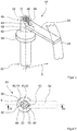
- FIG. 1 shows a perspective view of a guide vane for a first embodiment of a lever connection.
- a guide vane 10 shown in the installed position has, inter alia, a vane shank 12 extending along a vertical axis H with an airfoil 14.
- the vane 10 is pivotally receivable in a housing, not shown here, a turbomachine also not shown about the vertical axis H. Perpendicular to the vertical axis H, the machine longitudinal axis X of the turbomachine runs.
- a radially inner end 16 of the blade shank 12 a larger diameter, radially outer plate 18 is formed.
- a threaded portion 22 is provided.
- a radially inner airfoil root 24 of the airfoil 14 merges into a smaller diameter, radially inner plate 26, while a radially outer airfoil root 28 merges into the larger diameter plate 18.
- a longitudinal external toothing 30 extending parallel to the vertical axis H is formed on the blade shank 12.
- the longitudinal external toothing 30 can be designed as a uniform involute, trapezoidal, triangular toothing or the like.
- recess 34 is introduced, which, starting from the annular groove 32 via a small Length L extends in the direction of the radially inner end 16 of the blade shank 12.
- the recess 34 takes at least one tooth 36 of the longitudinal external teeth 30 completely and here by way of example a directly circumferentially to this adjacent further tooth 38 partially, wherein of the tooth 38 only a narrow side wall 40 stops.
- the recess 34 serves to receive a locking plate, not shown here (see. Insb. Fig. 3 . 4 . 6 ).
- the plate 18 also has an approximately annular contact surface 42 for a clamping sleeve of the lever connection (see. Fig. 2 ).
- FIG. 2 shows a perspective view of a clamping sleeve with an integrally formed laterally thereon lever for the first embodiment of the lever connection.
- a lever 52 of a drawing merely indicated guide vane adjustment 54 of the turbomachine integrally formed In the region of a radially outer end 46 of a substantially hollow cylindrical basic body 48 of a clamping sleeve 50 is a lever 52 of a drawing merely indicated guide vane adjustment 54 of the turbomachine integrally formed.
- the clamping sleeve 50 has an approximately disk-shaped collar 56 for securing the radial position of the guide vane in a housing of the turbomachine, not shown here.
- the clamping sleeve 50 has a longitudinal internal toothing 58 which corresponds to the longitudinal external toothing of the blade shank (see in particular. Fig.
- the vertical axis H in turn is orthogonal to the machine longitudinal axis X.
- the lever 52 At the radially outer end 46 of the clamping sleeve 50 is provided in the region of the base 48 of the clamping sleeve and the lever 52 has a recess 62 for the locking plate.
- the recess 62 has a first and a second side wall 64, 66 and a bottom 68, wherein the side walls 64, 66 are oriented perpendicular to the bottom 68.
- FIG. 3 illustrates a plan view of the first embodiment of the lever connection in an assembled state.
- the threaded portion 22 is connected to the blade shank 12 of the vane 10 with the clamping sleeve 50 by means of a preferably self-locking threaded nut 82 as a fastener 84 and pivotally received in a housing 86 of the turbomachine by means of the lever 52.
- the collar 56 of the clamping sleeve 50 secures the guide blade on one side in the radial direction.
- a locking plate 88 has two at least substantially triangular tabs 90, 92, which are brought to secure the threaded nut 82 by appropriate bending to the plant to this.
- the fuse element 88 is at least partially in the recess 62 of the lever 52 of the clamping sleeve 50.
- the locking plate 88 at least partially between this and the clamping sleeve 50 and the recess 62 in the lever 52 and the hidden here recess in the blade shank 12 clamped.
- FIG. 4 shows a longitudinal section of the mounted lever connection of Fig. 3 along the section line IV-IV.
- the vane 10 has the vane shank 12 and the blade 14 and the radially outer and the radially inner plates 18, 26.
- the vane 10 is located in relation to the machine longitudinal axis X in the installed position.
- the blade shank 12 of the vane 10 is inserted to form the lever connection 80 in the clamping sleeve 50 and clamped by means screwed onto the threaded portion 22 threaded nut 82, wherein between the collar 56 of the clamping sleeve 50 and the housing 86, a narrow gap 96 remains.
- the longitudinal external toothing 30 of the blade shank 12 and the longitudinal internal toothing 58 of the clamping sleeve 50 thus has a longitudinal positive connection 98.
- a cylindrical bearing portion 100 for pivotally supporting the guide vane 10 in a stepped bore 102 of the housing 86 is formed.
- three at least approximately hollow cylindrical bushes 104, 106, 108 are arranged here by way of example, wherein on the bushing 108 a vertically away from the vertical axis collar 110 is integrally formed between the plate 18 and a shoulder 112th the stepped bore 102 is located.
- the plate 18 further includes the abutment surface 42 as an abutment of along the vertical axis H against each other braced vane 10 and the clamping sleeve 50.
- the securing plate 88 also has a bore section 118 for passing through the threaded section 22 of the blade shank 12, perpendicular thereto that is parallel to the vertical axis H extending back portion 120 and a parallel to the machine axis X oriented clamping portion 122, which lies in the recess 34 of the longitudinal external teeth 30 of the blade shank 12 and in the recess 62 of the lever 52 of the clamping sleeve 50.
- the two recesses 34, 62 are in this case according to the invention designed such that at least the clamping portion 122 of the locking plate 88 wedged during clamping of the blade shank 12 with the clamping sleeve 50 between the blade shank 12 and the lever 52 to their play-free connection.
- a cross-sectional geometry of the bore portion 118, the back portion 120 and the clamping portion 122 of the locking plate 88 are approximately U-shaped.
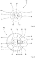
- FIG. 5 shows a cross section of the lever connection of Fig. 4 along the section line VV.
- the lever connection 80 is formed inter alia with the longitudinal external teeth 30 of the blade shank 12, which is in engagement with the longitudinal internal teeth 58 of the clamping sleeve 50 and in this case the longitudinal-side positive connection 98 represents.
- the clamping sleeve 50 with the blade shank 12, which is accommodated therein coaxially and in sections in a form-fitting manner, is pivotably received about the vertical axis H in the housing 86 in order to allow different angles of attack of the blade of the blade shank 12, which is not shown here.
- the centering of the blade shank 12 in the clamping sleeve 50 is in this case preferably on an outer diameter 124 of the longitudinal positive connection 98.
- the sleeve 104 among other things, a smooth and low-friction pivoting of the clamping sleeve 50 is ensured in the housing 86.
- FIG. 6 illustrates a cross section of the lever connection of Fig. 4 along the section line VI-VI.
- the blade shank 12 is non-rotatably connected by means of the longitudinally form-locking connection 98 of the lever connection 80 with the clamping sleeve 50 and the lever 52 integrally formed thereon and accommodated pivotably about the vertical axis H in the housing 86.
- the clamping portion 122 of the locking plate 88 is located in the recess 62 of the lever 52 and in the recess 34 of the longitudinal outer teeth 30 of the blade shank 12.
- the clamping portion 122 by tightening the threaded nut not shown here during assembly of the lever connection 80 between the side wall 40 of the remaining (Residual) tooth 38 and the opposite side wall 66 of the recess of the lever 62 wedged like a wedge.
- any circumferential clearance of the longitudinally-shaped interlocking connection 98 in relation to the vertical axis H is permanently and reliably eliminated.
- the clamping portion 122 is in this case connected by means of the parallel to the vertical axis H extending back portion 120 with the bow-shaped or clip-like locking plate 88.
- the locking plate 88 is exemplarily both the redundancy of the position assurance of the threaded nut and the backlash of the lever connection 80 causes.
- FIG. 7 shows a perspective view of a guide vane for a second embodiment of a lever connection.
- a guide vane 200 which in turn is shown in its installed position, comprises an at least substantially cylindrical vane shank 202 and an airfoil 204.
- the blade shank 202 has a radially inner end 206, in the region of which a larger diameter radially outer plate 208 is formed analogously to the first embodiment variant.
- a threaded portion 212 is provided at a radially outer end 210 of the blade shaft 202.
- a radially inner airfoil root 214 of the Blade blade 204 merges into a smaller diameter radially inner plate 216, while a radially outer blade root 218 connects to plate 208.
- a first spur toothing 220 instead of a longitudinal external toothing of the blade shaft 202 on the plate 208, a first spur toothing 220 with an irregular tooth pitch pointing in the direction of the threaded section 212 or the radially outer end 210 of the blade shaft 202 is provided.
- the spur gear 220 may have teeth with a deviating from the usual Evolentenform, virtually any geometry.
- an annular groove 222 and a cylindrical centering collar 224 adjoin the threaded portion 212 of the blade shaft 202.
- the centering collar 224 has a diameter D 2 which is at least slightly larger than a diameter D 1 of the blade shank 202.
- Peripheral to the spur gear 220 is further provided in the direction of the radially outer end 210 of the blade shank 202 facing bearing surface 234 for the clamping sleeve of the lever connection to the vane adjustment (see. FIG. 2 Reference numeral 54).
- FIG. 8 illustrates a perspective view of a clamping sleeve with an integrally molded laterally thereon lever for the second embodiment of the lever connection.
- a lever 242 is again preferably integrally formed for coupling the guide vane adjustment (not shown).
- FIG. 2 Reference numeral 54 According to the embodiment of FIG. 2 is on the main body 238 of the clamping sleeve 240 in turn a circumferential collar 246 and a flange integrally formed, which extends perpendicular to the vertical axis H radially outward.
- the base body 238 of the clamping sleeve 240 on a cylindrical and concentric to the vertical axis H extending through hole 248.
- the vertical axis H is again oriented at right angles to the machine longitudinal axis X.
- a second front toothing 252 with an irregular pitch which corresponds to the spur toothing of the blade shank of FIG. 7 is designed.
- a bore 256 or a recess for at least partially receiving a locking plate, not shown here is introduced.
- FIG. 9 shows a schematic side view of the second embodiment of the lever connection in an assembled state.
- the blade shank 202 merely indicated with the blade airfoil 204 is inserted into the clamping sleeve 240 to create the second embodiment of a lever connection 270.
- the blade shank 202 and the clamping sleeve 240 with the lever 242 and the flange-like collar 246 are braced against one another mechanically by means of a threaded nut 272 screwed onto the threaded section 212 and preferably self-locking as a fastening element 274 along the vertical axis H.
- a locking plate 276 for redundant rotation of the threaded nut 272 is also arranged against uncontrolled release.
- the clamping sleeve 240 encloses the blade shank 202 of the guide blade 200 in the assembled state in sections coaxially.
- the spur toothing 220 of the plate 208 is in the assembled state of the lever connection 270 shown here in positive engagement with the correspondingly shaped spur gearing 252 of the clamping sleeve 240 to create an inventive frontal positive connection 278, which also acts centering.
- the radially inner airfoil root 214 merges into the smaller diameter plate 216.
- the second embodiment of the lever connection 270 also enables an effective separation of the force flows or moments acting on the guide vane 200, since only minimal tension and the clamping sleeve 240 are subjected to bending or torsional moments in order to minimize local mechanical stresses of the vane shank 202.
- FIG. 10 shows a plan view of the mounted second embodiment of the lever connection of Fig. 9 ,
- the clamping sleeve 240 of the fully assembled lever connection 270 is fixed in position by means of the collar 246 at least on one side radially in the housing 86 of the turbomachine and pivotally received by the lever 242 about the vertical axis H.
- the blade shank 202 is clamped for this purpose by means of the screwed onto the threaded portion 212 threaded nut 272 in the direction of the vertical axis H with the clamping sleeve 240.
- the locking plate 276 is inserted between this and the clamping sleeve 240, which has a first and a second tab 280, 282. Further, the locking plate 276 has a parallel to the vertical axis H extending engagement portion 284, which is at least partially received in the bore 256 of the lever 242.
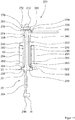
- FIG. 11 illustrates a longitudinal section through the mounted lever connection of Fig. 10 along the section line XI-XI.
- the vane shank 202 of the vane 200 is connected to the Clamping sleeve 240 is clamped by means of screwed onto the threaded portion 212 threaded nut 272 for producing the lever connection 270 along the vertical axis H, wherein a defined gap 290 between the housing 86 and the collar 246 of the clamping sleeve 240 remains.
- a cylindrical bearing portion 292 for pivotally mounting the guide vane 200 in a stepped bore 294 of the housing 86 is formed.
- the bearing section 292 and the stepped bore 294 only four hollow cylindrical bushes 296, 298, 300, 302 are arranged here by way of example, wherein between the sleeve 302 located furthest in the direction of the plate 208 and the annular contact surface 234 of the plate 208 as well a shoulder 304 is a hollow cylindrical intermediate layer 306.
- the contact surface 234 serves as an abutment of the along the vertical axis H against each other braced vane 200 and clamping sleeve 240 to create the lever connection 270.
- the centering collar 224 of the blade shank 202 also lies against an inner centering portion 308 of the clamping sleeve 240 for further optimization of the guide.
- the hook-like locking plate 276 comprises two triangular tabs, of which only the tab 282 is visible here, to which a bore section 310 adjoins, to which the engagement section 284 adjoins at right angles.
- the redundant position securing the threaded nut 272 by means of the locking plate 276, passes through the central bore portion 310 of the threaded portion 212 of the blade shaft 202 and which is clamped between the tightened nut 272 and the radially outer end 236 of the clamping sleeve 240.
- the two triangular tabs of the locking plate 276 can to ensure the purpose of the backup by bending to rest against the Threaded nut 272 or be brought to at least two of the hexagonal surfaces.
- the bore portion 310 of the locking plate 276 is added to the completion of the securing position of the threaded nut 272 in the bore 256 of the lever 242 of the clamping sleeve 240.
- the invention relates to two variants of a lever connection for pivoting guide vanes in a compressor part of a turbomachine in which a separation of the acting force and moment flows is realized by a clamping sleeve, such that the blade shank essentially only with tensile forces and the clamping sleeve primarily with bending or Torsionsmomenten is applied.
- a separation of the acting force and moment flows is realized by a clamping sleeve, such that the blade shank essentially only with tensile forces and the clamping sleeve primarily with bending or Torsionsmomenten is applied.
- the lever connection is permanently backlash-free and redundantly secured against uncontrolled loosening.
- a turbomachine having a multiplicity of lever connections according to the invention for adjusting guide vanes in a compressor part by means of the guide vane adjustment.
Landscapes
- Engineering & Computer Science (AREA)
- Mechanical Engineering (AREA)
- General Engineering & Computer Science (AREA)
- Structures Of Non-Positive Displacement Pumps (AREA)
Abstract
Description
- Die Erfindung betrifft zunächst eine Hebelanbindung zum drehfesten Verbinden einer Leitschaufel mit einem Hebel einer Leitschaufelverstellung einer Strömungsmaschine, wobei die Leitschaufel einen sich entlang einer Hochachse erstreckenden Schaufelschaft aufweist.
- Darüber hinaus hat die Erfindung eine Strömungsmaschine mit einer Vielzahl von Hebelanbindungen zum Herstellen einer drehfesten Ankopplung der Leitschaufeln an eine Leitschaufelverstellung.
- Verdichter in axialen Strömungsmaschinen, beispielsweise Flugzeugtriebwerken, umfassen in der Regel im Bereich der vorderen Verdichterstufen oder im Hochdruckverdichter eine Leitschaufelverstellung. Durch die Leitschaufelverstellung werden die Leitschaufeln der relevanten Leitschaufelreihe drehzahlabhängig um ihre Hochachse verstellt, so dass ein absoluter Leitradabströmwinkel veränderbar ist. Hierdurch kann ein Strömungsabriss beim Hochfahren der Strömungsmaschine bzw. bei geringen Drehzahlen verhindert werden. Eine Stufenbelastung wird reduziert. Alternativ könnte auch ein Strömungsabriss durch eine Verstellung der Laufschaufeln der Verdichterstufen verwirklicht werden, jedoch ist dies technisch wesentlich aufwändiger, so dass sich die Verstellung der Leitschaufeln durchgesetzt hat.
- Die Verstellung der Leitschaufeln einer Leitschaufelreihe erfolgt herkömmlicherweise mechanisch durch Betätigung eines Stellantriebs. Der Stellantrieb wirkt in der Regel über einen Verstellring und jeweils mittels eines Hebels auf die Leitschaufeln. Der Verstellring ist außerhalb der Strömungsmaschine angeordnet und gewöhnlich in Strömungsrichtung betrachtet hinter und koaxial zur Leitschaufelreihe positioniert. Er ist in Umfangsrichtung verdrehbar und in Axialrichtung der Strömungsmaschine verschiebbar. Bei mehreren zu verstellenden Verdichterstufen werden die Verstellringe gleichzeitig über einen drehbar am Verdichtergehäuse gelagerten Stellhebel des Stellantriebs angesteuert, der sich in Axialrichtung der Strömungsmaschine erstreckt und jeweils mit den Verstellringen verbunden ist.
- Bei bekannten Leitschaufelverstellungen wird der Hebel in Radialrichtung der Strömungsmaschine auf einen sich in Hochrichtung der Leitschaufel erstreckenden Schaufelschaft gesteckt. Danach wird der Hebel an einem in der Regel kleinflächigen Kontaktbereich des Schaufelschafts formschlüssig fixiert und mittels einer Verschraubung gesichert. Die Verschraubung kann durch ein Innengewinde oder durch ein Außengewinde erfolgen. Diese Art der Hebelanbindung erfordert einen ausreichend dicken Schaufelschaft für die Gestaltung der Kontaktflächen. Da die Formschlussverbindung jeweils nur endseitig und mit verhältnismäßig kleinen Kontaktflächen realisiert ist, können unter anderem lokal höhere mechanische Spannungen entstehen.
- Aufgabe der Erfindung ist es, eine Hebelanbindung einer Leitschaufelverstellung einer Strömungsmaschine zum Herstellen einer drehfesten Verbindung zwischen einer Leitschaufel und einem Hebel anzugeben, die die vorstehend genannten Nachteile vermeidet. Zudem ist es eine Aufgabe der Erfindung, eine Strömungsmaschine mit erfindungsgemäßen Hebelanbindungen anzugeben.
- Die Aufgabe wird zunächst durch eine Hebelanbindung mit den Merkmalen des Patentanspruchs 1 gelöst.
- Bei einer Hebelanbindung zum drehfesten Verbinden einer Leitschaufel mit einem Hebel einer Leitschaufelverstellung einer Strömungsmaschine, wobei die Leitschaufel einen sich entlang einer Hochachse erstreckenden Schaufelschaft aufweist, ist der Hebel einstückig an einem radial äußeren Ende einer den Schaufelschaft abschnittsweise koaxial umschließenden, im Wesentlichen hohlzylindrischen Spannhülse ausgebildet und der Schaufelschaft und die Spannhülse sind über eine längsseitige Formschlussverbindung oder eine stirnseitige Formschlussverbindung gekoppelt und der Schaufelschaft ist mittels eines Befestigungselements, insbesondere einer Gewindemutter, mit der Spannhülse entlang der Hochachse verspannbar.
- Hierdurch ist eine Trennung der Kraftflüsse gegeben, da der Schaufelschaft im Wesentlichen nur auf Zug und die Spannhülse mittels des integral daran angeformten Hebels zumindest im Wesentlichen nur durch Biegemomente beim Verstellen der Leitschaufel beaufschlagt wird. Im Vergleich zu einer hergebrachten Hebelanbindung wird die Gefahr des Entstehens von lokal erhöhten mechanischen Spannungen vermindert und insgesamt eine gleichmäßigere Lastverteilung erreicht. Die längsseitige Formschlussverbindung erstreckt sich ebenfalls parallel zur Hochachse des Schaufelschaftes. Die Gewindemutter ist üblicherweise selbstsichernd ausgeführt. Anstelle einer Gewindemutter kann zum Beispiel ein Gewindebolzen als Spann- bzw.- Befestigungselement zum Einsatz kommen.
- Bevorzugt weist die Spannhülse einen Bund zur radialen Lagesicherung der Leitschaufel in einem Gehäuse der Strömungsmaschine auf, wobei zwischen dem Bund und dem Gehäuse ein definierter Spalt besteht. Infolgedessen ist eine leichtgängige Lagerung gegeben.
- Nach Maßgabe einer technisch vorteilhaften Weiterbildung ist zwischen einem radial inneren Ende der Spannhülse und dem Bund der Spannhülse ein zylindrischer Lagerabschnitt zur verschwenkbaren Lagerung der Leitschaufel in dem Gehäuse ausgebildet. Infolgedessen ist eine besonders große Kontaktfläche zwischen Spannhülse und dem Gehäuse der Strömungsmaschine gegeben, woraus eine robuste und haltbare Lagerung resultiert.
- Bevorzugt ist zwischen einer Bohrung des Gehäuses und dem Lagerabschnitt der Spannhülse mindestens eine Buchse angeordnet. Hierdurch ist im Fall einer geeigneten Materialauswahl der Spannhülse, der mindestens einen zumindest annähernd hohlzylindrischen Buchse sowie des Gehäuses der Strömungsmaschine in diesem Bereich eine verschleißarme Lagerung möglich. Zudem ist mittels der mindestens einen Buchse ein Toleranzausgleich realisierbar.
- Vorzugsweise ist an einem radial äußeren Ende des Schaufelschaftes ein Gewindeabschnitt für die Gewindemutter ausgebildet. Infolgedessen ist eine mechanisch zuverlässige sowie erforderlichenfalls wieder lösbare Verbindung zwischen dem Schaufelschaft und der Spannhülse gegeben.
- Vorzugsweise bildet der radial äußere Teller der Leitschaufel eine Anlagefläche für das radial innere Ende der Spannhülse aus. Hierdurch ist an dem Schaufelschaft ein einseitiges Widerlager für die Spannhülse gegeben.
- Im Fall einer ersten Ausführungsvariante der Hebelanbindung weist der Schaufelschaft eine Längsaußenverzahnung mit einer ersten Aussparung unterhalb des Gewindeabschnitts und die Spannhülse eine Längsinnenverzahnung mit einer zweiten Aussparung im Bereich des Hebels zur Schaffung der längsseitigen Formschlussverbindung auf, wobei die beiden Aussparungen derart ausgebildet sind, dass ein in den Aussparungen passgenau aufnehmbares Sicherungsblech beim Verspannen des Schaufelschaftes mit der Spannhülse zwischen dem Schaufelschaft und dem Hebel zu deren spielfreier Verbindung einklemmbar ist. Hierdurch ist eine dauerhaft spielfreie, drehfeste Verbindung zwischen der Spannhülse mit dem Hebel und dem Schaufelschaft gegeben. Eine Übertragung der Verstellmomente erfolgt mittels der längsseitigen Formschlussverbindung, während die Übertragung von Biegemomenten über die Spannhülse mit dem Hebel geschieht, was eine Aufteilung dieser verschiedenen Kraftflüsse bewirkt. Das Sicherungsblech dient darüber hinaus zur Lagesicherung der bevorzugt selbstsichernden Gewindemutter.
- Im Fall einer zweiten Ausführungsform der Hebelanbindung ist die stirnseitige Formschlussverbindung mit einer ersten in Richtung des äußeren radialen Endes des Schaufelschafts gerichteten Stirnverzahnung am radial äußeren Teller und mit einer in Richtung der ersten Stirnverzahnung gerichteten zweiten Stirnverzahnung am radial inneren Ende der Spannhülse gebildet. Aufgrund der entgegengesetzt orientierten und miteinander in einem zumindest bereichsweise formschlüssigen Eingriff stehenden Stirnverzahnungen ist eine dauerhaft spielfreie Verbindung zwischen der Spannhülse mit dem Hebel und dem Schaufelschaft gegeben. Darüber hinaus gewährleisten die beiden Stirnverzahnungen eine einwandfreie Zentrierung der Spannhülse in Bezug zu dem Schaufelschaft. Der Schaufelschaft bleibt im Ergebnis vollkommen frei von Biege- bzw. Torsionsmomenten und ist demnach ausschließlich auf Zug belastet, woraus eine strikte Kraftflusstrennung resultiert, wodurch das Auftreten von lokalen mechanischen Spannungen innerhalb der Leitschaufel weitestgehend vermieden wird.
- Bevorzugt weisen die beiden Stirnverzahnungen jeweils eine unregelmäßige Zahnteilung auf. Infolgedessen ist eine eindeutige Winkelposition zwischen dem Schaufelschaft und der Spannhülse zur Erleichterung der Montage der Hebelanbindung gegeben.
- Im Fall einer technisch günstigen Ausgestaltung ist im Bereich der Spannhülse und/oder des Hebels eine Ausnehmung für ein Sicherungsblech zur Lagesicherung der Gewindemutter vorgesehen. Hierdurch ist neben der bevorzugt selbstsichernd ausgeführten Gewindemutter eine weitere Sicherung der Gewindemutter gegen unbeabsichtigtes Lösen gegeben.
- Vorzugsweise weist der Schaufelschaft einen zumindest näherungsweise zylindrischen Zentrierbund auf, der zumindest abschnittsweise an einem Innenzentrierabschnitt im Bereich des radial äußeren Endes der Spannhülse anliegt. Hierdurch ist eine verlässliche Führung des Schaufelschafts in der Spannhülse gegeben.
- Eine erfindungsgemäße Strömungsmaschine ist mit einer Vielzahl von Hebelanbindungen nach einem der Patentansprüche 1 bis 11 zum Herstellen einer drehfesten Ankopplung von Leitschaufeln an eine Leitschaufelverstellung ausgestattet. Infolgedessen ist eine Entkopplung der Kraftflüsse gegeben, wodurch die Gefahr der Entstehung lokaler mechanischer Spannungsspitzen vermieden wird.
- Es zeigen schematisch:
- Figur 1:
- eine perspektivische Ansicht einer Leitschaufel für eine erste Ausführungsvariante einer Hebelanbindung,
- Figur 2:
- eine perspektivische Ansicht einer Spannhülse mit einem einstückig seitlich daran ausgebildeten Hebel für die erste Ausführungsvariante der Hebelanbindung,
- Figur 3:
- eine Draufsicht auf die erste Ausführungsvariante der Hebelanbindung in einem montierten Zustand,
- Figur 4:
- einen Längsschnitt der montierten Hebelanbindung von
Fig. 3 entlang der Schnittlinie IV-IV, - Figur 5:
- einen Querschnitt der Hebelanbindung von
Fig. 4 entlang der Schnittlinie V-V, - Figur 6:
- einen Querschnitt der Hebelanbindung von
Fig. 4 entlang der Schnittlinie VI-VI, - Figur 7:
- eine perspektivische Ansicht einer Leitschaufel für eine zweite Ausführungsvariante einer Hebelanbindung,
- Figur 8:
- eine perspektivische Ansicht einer Spannhülse mit einem einstückig seitlich daran ausgeformten Hebel für die zweite Ausführungsvariante der Hebelanbindung,
- Figur 9:
- eine schematische Seitenansicht auf die zweite Ausführungsvariante der Hebelanbindung in einem montierten Zustand,
- Figur 10:
- eine Draufsicht auf die montierte zweite Ausführungsform der Hebelanbindung von
Fig. 9 , - Figur 11:
- einen Längsschnitt durch die montierte Hebelanbindung von
Fig. 10 entlang der Schnittlinie XI-XI. - Im Kontext der vorliegenden Beschreibung beziehen sich Begriffe wie "radial", "radial außen", "radial äußere", "radial innen" sowie "radial innere" - soweit nicht ausdrücklich auf eine andere Orientierung hingewiesen ist - auf eine Maschinenlängsachse X der erfindungsgemäßen Strömungsmaschine, die die Drehachse eines Rotors der Strömungsmaschine verkörpert.
- Angaben wie "seitlich" und "quer" beziehen sich auf eine Hochachse H einer Leitschaufel der Strömungsmaschine, die im Wesentlichen radial zur Maschinenlängsachse X verläuft.
-
Figur 1 zeigt eine perspektivische Ansicht einer Leitschaufel für eine erste Ausführungsvariante einer Hebelanbindung. Eine in Einbaulage dargestellte Leitschaufel 10 weist unter anderem einen sich entlang einer Hochachse H erstreckenden Schaufelschaft 12 mit einem Schaufelblatt 14 auf. Die Leitschaufel 10 ist in einem hier nicht dargestellten Gehäuse einer gleichfalls nicht dargestellten Strömungsmaschine um die Hochachse H verschwenkbar aufnehmbar. Senkrecht zu der Hochachse H verläuft die Maschinenlängsachse X der Strömungsmaschine. An einem radial inneren Ende 16 des Schaufelschafts 12 ist ein durchmessergrößerer, radial äußerer Teller 18 ausgebildet. An einem radial äußeren Ende 20 des Schaufelschafts 12 ist ein Gewindeabschnitt 22 vorgesehen. Eine radial innere Schaufelblattwurzel 24 des Schaufelblatts 14 geht in einen durchmesserkleineren, radial inneren Teller 26 über, während eine radial äußere Schaufelblattwurzel 28 in den durchmessergrößeren Teller 18 übergeht. - An dem Schaufelschaft 12 ist zumindest abschnittsweise eine parallel zur Hochachse H verlaufende Längsaußenverzahnung 30 ausgebildet. Die Längsaußenverzahnung 30 kann als eine gleichmäßige Evolventen-, Trapez-, Dreiecksverzahnung oder dergleichen ausgestaltet sein. Zwischen dem Gewindeabschnitt 22 und der Längsaußenverzahnung 30 befindet sich eine hohlkehlartige Ringnut 32 bzw. eine Einschnürung des Schaufelschafts 12. In den Schaufelschaft 12 ist eine ungefähr quaderförmige sowie parallel zur Hochachse H verlaufende Aussparung 34 eingebracht, die sich ausgehend von der Ringnut 32 über eine geringe Länge L in Richtung des radial inneren Endes 16 des Schaufelschafts 12 erstreckt. Die Aussparung 34 nimmt mindestens einen Zahn 36 der Längsaußenverzahnung 30 vollständig und hier beispielhaft einen unmittelbar umfangsseitig zu diesem benachbarten weiteren Zahn 38 teilweise ein, wobei von dem Zahn 38 lediglich eine schmale Seitenwand 40 stehen bleibt. Die Aussparung 34 dient zur Aufnahme eines hier nicht dargestellten Sicherungsblechs (vgl. insb.
Fig. 3 ,4 ,6 ). Der Teller 18 verfügt ferner über eine in etwa kreisringförmige Anlagefläche 42 für eine Spannhülse der Hebelanbindung (vgl. insb.Fig. 2 ). -
Figur 2 zeigt eine perspektivische Ansicht einer Spannhülse mit einem einstückig seitlich daran ausgebildeten Hebel für die erste Ausführungsvariante der Hebelanbindung. Im Bereich eines radial äußeren Endes 46 eines im Wesentlichen hohlzylindrischen Grundkörpers 48 einer Spannhülse 50 ist ein Hebel 52 einer zeichnerisch lediglich angedeuteten Leitschaufelverstellung 54 der Strömungsmaschine einstückig ausgebildet. Die Spannhülse 50 verfügt über einen näherungsweise scheibenförmigen Bund 56 zur radialen Lagesicherung der Leitschaufel in einem hier nicht dargestellten Gehäuse der Strömungsmaschine. Die Spannhülse 50 verfügt über eine Längsinnenverzahnung 58, die korrespondierend zur Längsaußenverzahnung des Schaufelschafts (vgl. insb.Fig. 1 ) ausgeführt ist und die sich ausgehend von dem radial äußeren Ende 46 bis zu einem radial inneren Ende 60 der Spannhülse 50 parallel zur Hochachse H erstreckt. Die Hochachse H verläuft wiederum orthogonal zur Maschinenlängsachse X. An dem radial äußeren Ende 46 der Spannhülse 50 ist im Bereich des Grundkörpers 48 der Spannhülse sowie im Hebel 52 eine Aussparung 62 für das Sicherungsblech vorgesehen. Die Aussparung 62 verfügt über eine erste und eine zweite Seitenwand 64, 66 sowie einen Boden 68, wobei die Seitenwände 64, 66 senkrecht zum Boden 68 orientiert sind. -
Figur 3 illustriert eine Draufsicht auf die erste Ausführungsvariante der Hebelanbindung in einem montierten Zustand. In einem montierten Zustand einer erfindungsgemäßen Hebelanbindung 80 ist der Gewindeabschnitt 22 am Schaufelschaft 12 der Leitschaufel 10 mit der Spannhülse 50 mittels einer bevorzugt selbstsichernden Gewindemutter 82 als Befestigungselement 84 verbunden und in einem Gehäuse 86 der Strömungsmaschine mittels des Hebels 52 verschwenkbar aufgenommen. Der Bund 56 der Spannhülse 50 sichert hierbei die Leitschaufel einseitig in radialer Richtung. Ein Sicherungsblech 88 weist zwei zumindest im Wesentlichen dreieckförmige Laschen 90, 92 auf, die zur Sicherung der Gewindemutter 82 durch entsprechendes Biegen zur Anlage an diese gebracht werden. Das Sicherungselement 88 liegt zumindest abschnittsweise in der Aussparung 62 des Hebels 52 der Spannhülse 50. Bei der Montage der Hebelanbindung 80 durch das Festziehen bzw. Anziehen der Gewindemutter 82 wird das Sicherungsblech 88 zumindest abschnittsweise zwischen dieser und der Spannhülse 50 und der Aussparung 62 im Hebel 52 sowie der hier verdeckten Aussparung im Schaufelschaft 12 festgeklemmt. -
Figur 4 zeigt einen Längsschnitt der montierten Hebelanbindung vonFig. 3 entlang der Schnittlinie IV-IV. Die Leitschaufel 10 verfügt über den Schaufelschaft 12 und das Schaufelblatt 14 sowie den radial äußeren und den radial inneren Teller 18, 26. Die Leitschaufel 10 befindet sich in Bezug zur Maschinenlängsachse X in Einbaulage. Der Schaufelschaft 12 der Leitschaufel 10 ist zur Ausbildung der Hebelanbindung 80 in die Spannhülse 50 eingeschoben und mittels der auf den Gewindeabschnitt 22 aufgeschraubten Gewindemutter 82 verspannt, wobei zwischen dem Bund 56 der Spannhülse 50 und dem Gehäuse 86 ein schmaler Spalt 96 verbleibt. Zwischen der Längsaußenverzahnung 30 des Schaufelschafts 12 und der Längsinnenverzahnung 58 der Spannhülse 50 besteht somit eine längsseitige Formschlussverbindung 98. - Zwischen dem radial inneren Ende 60 der Spannhülse 50 und dem Bund 56 ist ein zylindrischer Lagerabschnitt 100 zur verschwenkbaren Lagerung der Leitschaufel 10 in einer gestuften Bohrung 102 des Gehäuses 86 ausgebildet. Zwischen dem Lagerabschnitt 100 und der gestuften Bohrung 102 sind hier beispielhaft drei zumindest annähernd hohlzylindrische Buchsen 104, 106, 108 angeordnet, wobei an der Buchse 108 ein senkrecht von der Hochachse weggerichteter Kragen 110 integral ausgeformt ist, der zwischen dem Teller 18 und einer Schulter 112 der gestuften Bohrung 102 liegt. Der Teller 18 weist ferner die Anlagefläche 42 als ein Widerlager der entlang der Hochachse H gegeneinander verspannten Leitschaufel 10 und der Spannhülse 50 auf.
- Mittels der Lasche 90 und der hier nicht sichtbaren, zweiten Lasche des Sicherungsblechs 88 erfolgt eine zusätzliche Verdrehsicherung der darüber hinaus bevorzugt selbstsichernden Gewindemutter 82. Das Sicherungsblech 88 verfügt ferner über einen Bohrungsabschnitt 118 zur Durchführung des Gewindeabschnitts 22 des Schaufelschafts 12, einen sich senkrecht daran anschließenden, das heißt parallel zur Hochachse H verlaufenden Rückenabschnitt 120 sowie einen parallel zur Maschinenlängsachse X orientierten Klemmabschnitt 122, der in der Aussparung 34 der Längsaußenverzahnung 30 des Schaufelschafts 12 und in der Aussparung 62 des Hebels 52 der Spannhülse 50 liegt. Die beiden Aussparungen 34, 62 sind hierbei erfindungsgemäß derart ausgeführt, dass sich zumindest der Klemmabschnitt 122 des Sicherungsblechs 88 beim Verspannen des Schaufelschafts 12 mit der Spannhülse 50 keilartig zwischen dem Schaufelschaft 12 und dem Hebel 52 zu deren spielfreier Verbindung einklemmt. Eine Querschnittsgeometrie des Bohrungsabschnitts 118, des Rückenabschnitts 120 und des Klemmabschnitts 122 des Sicherungsblechs 88 verlaufen ungefähr U-förmig.
- Durch die erfindungsgemäße Ausbildung der Hebelanbindung 80 ist eine Trennung von auf die Leitschaufel 10 einwirkenden Kraftflüssen zum Schutz vor lokalen Lastspitzen gewährleistet, da Verstellmomente über die längsseitige Formschlussverbindung 98 und Biege- oder Torsionsmomente durch den Hebel 52 und die Spannhülse 50 auf die Leitschaufel 10 übertragen werden.
-
Figur 5 zeigt einen Querschnitt der Hebelanbindung vonFig. 4 entlang der Schnittlinie V-V. Die Hebelanbindung 80 ist unter anderem mit der Längsaußenverzahnung 30 des Schaufelschafts 12 gebildet, die im Eingriff mit der Längsinnenverzahnung 58 der Spannhülse 50 steht und hierbei die längsseitige Formschlussverbindung 98 darstellt. Die Spannhülse 50 mit dem darin koaxial und abschnittsweise formschlüssig aufgenommenen Schaufelschaft 12 ist um die Hochachse H verschwenkbar im Gehäuse 86 aufgenommen, um unterschiedliche Anstellwinkel der hier nicht dargestellten Schaufel des Schaufelschafts 12 zu ermöglichen. Die Zentrierung der Schaufelschafts 12 in der Spannhülse 50 erfolgt hierbei bevorzugt an einem Außendurchmesser 124 der längsseitigen Formschlussverbindung 98. Durch die Buchse 104 ist unter anderem eine leichtgängige und reibungsarme Verschwenkbarkeit der Spannhülse 50 in dem Gehäuse 86 gewährleistet. -
Figur 6 illustriert einen Querschnitt der Hebelanbindung vonFig. 4 entlang der Schnittlinie VI-VI. Der Schaufelschaft 12 ist mittels der längsseitigen Formschlussverbindung 98 der Hebelanbindung 80 drehfest mit der Spannhülse 50 und dem daran integral ausgebildeten Hebel 52 verbunden und verschwenkbar um die Hochachse H in dem Gehäuse 86 aufgenommen. Der Klemmabschnitt 122 des Sicherungsblechs 88 liegt in der Aussparung 62 des Hebels 52 und in der Aussparung 34 der Längsaußenverzahnung 30 des Schaufelschafts 12. Der Klemmabschnitt 122 wird durch das Anziehen der hier nicht dargestellten Gewindemutter bei der Montage der Hebelanbindung 80 zwischen der Seitenwand 40 des verbliebenen (Rest-)Zahns 38 und der gegenüberliegenden Seitenwand 66 der Aussparung des Hebels 62 keilartig eingeklemmt. Infolgedessen wird ein etwaiges Umfangsspiel der längsseitigen Formschlussverbindung 98 in Relation zur Hochachse H dauerhaft und zuverlässig eliminiert. Der Klemmabschnitt 122 ist hierbei mittels des parallel zur Hochachse H verlaufenden Rückenabschnitts 120 mit dem bügelförmigen bzw. klammerartigen Sicherungsblech 88 verbunden. Durch das Sicherungsblech 88 wird hier exemplarisch sowohl die Redundanz der Lagesicherung der Gewindemutter als auch die Spielfreiheit der Hebelanbindung 80 bewirkt. -
Figur 7 zeigt eine perspektivische Ansicht einer Leitschaufel für eine zweite Ausführungsvariante einer Hebelanbindung. Eine wiederum in ihrer Einbaulage dargestellte Leitschaufel 200 umfasst einen zumindest im Wesentlichen zylindrischen Schaufelschaft 202 und ein Schaufelblatt 204. Zur Verdeutlichung der räumlichen Lage der Komponenten innerhalb der Strömungsmaschine sind wieder die Hochachse H sowie die Maschinenlängsachse X eingezeichnet. Der Schaufelschaft 202 verfügt über ein radial inneres Ende 206, in dessen Bereich ein durchmessergrößerer radial äußerer Teller 208 analog zur ersten Ausführungsvariante ausgebildet ist. An einem radial äußeren Ende 210 des Schaufelschafts 202 ist ein Gewindeabschnitt 212 vorgesehen. Eine radial innere Schaufelblattwurzel 214 des Schaufelblatts 204 geht in einen durchmesserkleineren radial inneren Teller 216 über, während eine radial äußere Schaufelblattwurzel 218 an den Teller 208 anschließt. Als ein Unterschied zuFig. 1 ist anstelle einer Längsaußenverzahnung des Schaufelschafts 202 an dem Teller 208 eine in Richtung des Gewindeabschnitts 212 bzw. des radial äußeren Endes 210 des Schaufelschafts 202 weisende erste Stirnverzahnung 220 mit einer unregelmäßigen Zahnteilung vorgesehen. Die Stirnverzahnung 220 kann Zähne mit einer von der üblichen Evolentenform abweichenden, praktisch beliebigen Geometrie aufweisen. Entlang der Hochachse H in Richtung des Tellers 208 schließen sich an den Gewindeabschnitt 212 des Schaufelschafts 202 eine Ringnut 222 sowie ein zylindrischer Zentrierbund 224 an. Der Zentrierbund 224 weist einen im Vergleich zu einem Durchmesser D1 des Schaufelschafts 202 zumindest geringfügig größer bemessenen Durchmesser D2 auf. Peripher zur Stirnverzahnung 220 ist ferner eine in Richtung des radial äußeren Endes 210 des Schaufelschafts 202 weisende Anlagefläche 234 für die Spannhülse der Hebelanbindung zur Leitschaufelverstellung vorgesehen (vgl.Figur 2 , Bezugsziffer 54). -
Figur 8 illustriert eine perspektivische Ansicht einer Spannhülse mit einem einstückig seitlich daran ausgeformten Hebel für die zweite Ausführungsvariante der Hebelanbindung. An einem radial äußeren Ende 236 eines zumindest annähernd hohlzylindrischen Grundkörpers 238 einer zweiten Ausführungsvariante einer in Einbaulage gezeichneten Spannhülse 240 ist wiederum ein Hebel 242 bevorzugt einstückig zur Ankopplung der hier nicht dargestellten Leitschaufelverstellung ausgebildet (vgl.Figur 2 , Bezugsziffer 54). Entsprechend zur Ausführungsvariante vonFigur 2 ist an dem Grundkörper 238 der Spannhülse 240 wiederum ein umlaufender Bund 246 bzw. ein Flansch integral ausgeformt, der sich senkrecht zur Hochachse H radial nach außen erstreckt. Abweichend von der Längsinnenverzahnung der ersten Ausführungsvariante der Spannhülse (vgl.Figur 2 ) weist der Grundkörper 238 der Spannhülse 240 eine zylindrische und konzentrisch zur Hochachse H verlaufende Durchgangsbohrung 248 auf. Die Hochachse H ist dabei wiederum rechtwinklig zur Maschinenlängsachse X orientiert. An einem radial inneren Ende 250 der Spannhülse 240 ist als weitere konstruktive Differenz eine zweite Stirnverzahnung 252 mit einer unregelmäßigen Zahnteilung vorgesehen, die korrespondierend zu der Stirnverzahnung der Schaufelschafts vonFigur 7 ausgestaltet ist. In einer hohlkehlartigen Übergangszone 254 zwischen dem radial äußeren Ende 236 der Spannhülse 240 und dem Hebel 242 ist eine Bohrung 256 bzw. eine Aussparung zur zumindest teilweisen Aufnahme eines hier nicht dargestellten Sicherungsblechs eingebracht. -
Figur 9 zeigt eine schematische Seitenansicht auf die zweite Ausführungsvariante der Hebelanbindung in einem montierten Zustand. Der zeichnerisch lediglich angedeutete Schaufelschaft 202 mit dem Schaufelblatt 204 ist in die Spannhülse 240 zur Schaffung der zweiten Ausführungsvariante einer Hebelanbindung 270 eingeschoben. Der Schaufelschaft 202 und die Spannhülse 240 mit dem Hebel 242 sowie dem flanschartigen Bund 246 sind mittels einer auf den Gewindeabschnitt 212 aufgeschraubten sowie bevorzugt selbstsichernd ausgeführten Gewindemutter 272 als Befestigungselement 274 entlang der Hochachse H mechanisch gegeneinander verspannt. Zwischen der Gewindemutter 272 und dem radial äußeren Ende 236 der Spannhülse 240 ist ferner ein Sicherungsblech 276 zur redundanten Verdrehsicherung der Gewindemutter 272 gegen unkontrolliertes Lösen angeordnet. Die Spannhülse 240 umschließt den Schaufelschaft 202 der Leitschaufel 200 im montierten Zustand abschnittsweise koaxial. Die Stirnverzahnung 220 des Tellers 208 befindet sich in dem hier gezeigten Montagezustand der Hebelanbindung 270 im formschlüssigen Eingriff mit der korrespondierend geformten Stirnverzahnung 252 der Spannhülse 240 unter Schaffung einer erfindungsgemäß stirnseitigen Formschlussverbindung 278, die zugleich zentrierend wirkt. Die radial innere Schaufelblattwurzel 214 geht in den durchmesserkleineren Teller 216 über. - Die zweite Ausführungsvariante der Hebelanbindung 270 ermöglicht ebenfalls eine wirkungsvolle Trennung der auf die Leitschaufel 200 einwirkenden Kraftflüsse bzw. Momente, da zur Minimierung lokaler mechanischer Spannungen der Schaufelschaft 202 ausschließlich auf Zug und die Spannhülse 240 nur mit Biege- bzw. Torsionsmomenten beaufschlagt ist.
-
Figur 10 zeigt eine Draufsicht auf die montierte zweite Ausführungsform der Hebelanbindung vonFig. 9 . Die Spannhülse 240 der fertig montierten Hebelanbindung 270 ist mittels des Bundes 246 zumindest einseitig radial in dem Gehäuse 86 der Strömungsmaschine lagefixiert und mittels des Hebels 242 um die Hochachse H verschwenkbar aufgenommen. Der Schaufelschaft 202 ist zu diesem Zweck mittels der auf dessen Gewindeabschnitt 212 aufgeschraubten Gewindemutter 272 in Richtung der Hochachse H mit der Spannhülse 240 verspannt. Zur Lagesicherung der Gewindemutter 272 ist zwischen dieser und der Spannhülse 240 das Sicherungsblech 276 eingelegt, das eine erste und eine zweite Lasche 280, 282 aufweist. Ferner verfügt das Sicherungsblech 276 über einen parallel zur Hochachse H verlaufenden Eingriffsabschnitt 284, der zumindest bereichsweise in der Bohrung 256 des Hebels 242 aufgenommen ist. -
Figur 11 veranschaulicht einen Längsschnitt durch die montierte Hebelanbindung vonFig. 10 entlang der Schnittlinie XI-XI. Der Schaufelschaft 202 der Leitschaufel 200 ist mit der Spannhülse 240 mittels der auf den Gewindeabschnitt 212 aufgeschraubten Gewindemutter 272 zur Herstellung der Hebelanbindung 270 entlang der Hochachse H verspannt, wobei ein definierter Spalt 290 zwischen dem Gehäuse 86 und dem Bund 246 der Spannhülse 240 verbleibt. Hierdurch ist eine leichtgängige Verschwenkbarkeit der Leitschaufel 200 um die Hochachse H durch Betätigen des integral zur Spannhülse 240 ausgeformten Hebels 242 mittels der hier nicht dargestellten Leitschaufelverstellung der Strömungsmaschine gewährleistet (vgl.Figur. 2 , Bezugsziffer 54). Die drehfeste sowie zugleich dauerhaft spielfreie Verbindung zwischen dem Schaufelschaft 202 der Leitschaufel 200 und der Spannhülse 240 ist durch die entlang der Hochachse H verspannte stirnseitige Formschlussverbindung 278 gewährleistet, die mit der Stirnverzahnung 220 des Tellers 208 und der mit dieser im Eingriff befindlichen Stirnverzahnung 252 am radial inneren Ende 250 der Spannhülse 240 gebildet ist. Die Schaufel 204 ist zwischen dem Teller 208 und dem durchmesserkleineren Teller 216 integral zu diesen ausgebildet. - Zwischen dem radial inneren Ende 250 der Spannhülse 240 und deren Bund 246 ist ein zylindrischer Lagerabschnitt 292 zur verschwenkbaren Lagerung der Leitschaufel 200 in einer gestuften Bohrung 294 des Gehäuses 86 ausgebildet. Zwischen dem Lagerabschnitt 292 und der gestuften Bohrung 294 sind hier lediglich exemplarisch vier zumindest jeweils annähernd hohlzylindrische Buchsen 296, 298, 300, 302 angeordnet, wobei zwischen der am weitesten in Richtung des Tellers 208 befindlichen Buchse 302 und der kreisringförmigen Anlagefläche 234 des Tellers 208 sowie einer Schulter 304 ein hohlzylindrischer Zwischenleger 306 liegt. Die Anlagefläche 234 dient als ein Widerlager der entlang der Hochachse H gegeneinander verspannten Leitschaufel 200 und Spannhülse 240 zur Schaffung der Hebelanbindung 270. Der Zentrierbund 224 des Schaufelschafts 202 liegt zudem an einer Innenzentrierabschnitt 308 der Spannhülse 240 zur weiteren Optimierung der Führung an.
- Das hakenartige Sicherungsblech 276 umfasst zwei dreieckförmige Laschen, von denen hier nur die Lasche 282 sichtbar ist, an die sich ein Bohrungsabschnitt 310 anschließt, an den sich rechtwinklig der Eingriffsabschnitt 284 anschließt. Die redundante Lagesicherung der Gewindemutter 272 erfolgt mittels des Sicherungsblechs 276, durch dessen mittigen Bohrungsabschnitt 310 der Gewindeabschnitt 212 des Schaufelschafts 202 verläuft und der zwischen der angezogenen Gewindemutter 272 und dem radial äußeren Ende 236 der Spannhülse 240 eingeklemmt ist. Die beiden dreieckförmigen Laschen des Sicherungsblechs 276 können zur Gewährleistung des Sicherungszwecks durch Aufbiegen zur Anlage an die Gewindemutter 272 bzw. an mindestens zwei von deren Sechskantflächen gebracht werden. Der Bohrungsabschnitt 310 des Sicherungsblechs 276 ist zur Komplettierung der Lagesicherung der Gewindemutter 272 in der Bohrung 256 des Hebels 242 der Spannhülse 240 aufgenommen.
- Die Erfindung betrifft zwei Ausführungsvarianten einer Hebelanbindung zum Verschwenken von Leitschaufeln in einem Verdichterteil einer Strömungsmaschine, bei der durch eine Spannhülse eine Trennung der einwirkenden Kraft- und Momentenflüsse realisiert ist, derart, dass der Schaufelschaft im Wesentlichen nur mit Zugkräften und die Spannhülse primär mit Biege- bzw. Torsionsmomenten beaufschlagt ist. Infolgedessen werden lokale mechanische Lastspitzen beträchtlich reduziert. Zudem ist die Hebelanbindung dauerhaft spielfrei und gegen unkontrolliertes Lösen redundant gesichert. Offenbart ist weiterhin eine Strömungsmaschine mit einer Vielzahl von erfindungsgemäßen Hebelanbindungen zum Verstellen von Leitschaufeln in einem Verdichterteil mittels der Leitschaufelverstellung.
-
- 10
- Leitschaufel (1. Var.)
- 12
- Schaufelschaft
- 14
- Schaufelblatt
- 16
- radial inneres Ende (Schaufelschaft)
- 18
- radial äußerer Teller
- 20
- radial äußeres Ende (Schaufelschaft)
- 22
- Gewindeabschnitt
- 24
- radial innere Schaufelblattwurzel
- 26
- radial innerer Teller
- 28
- radial äußere Schaufelblattwurzel
- 30
- Längsaußenverzahnung (Schaufelschaft)
- 32
- Ringnut
- 34
- Aussparung (Längsaußenverzahnung)
- 36
- Zahn
- 38
- Zahn
- 40
- Seitenwand (Zahn)
- 42
- Anlagefläche (Teller)
- 46
- radial äußeres Ende (Spannhülse)
- 48
- Grundkörper (Spannhülse)
- 50
- Spannhülse (1. Var.)
- 52
- Hebel
- 54
- Leitschaufelverstellung
- 56
- Bund
- 58
- Längsinnenverzahnung (Spannhülse)
- 60
- radial inneres Ende (Spannhülse)
- 62
- Aussparung (Spannhülse, Hebel)
- 64
- erste Seitenwand
- 66
- zweite Seitenwand
- 68
- Boden
- 80
- Hebelanbindung (1. Var.)
- 82
- Gewindemutter
- 84
- Befestigungselement
- 86
- Gehäuse (Strömungsmaschine)
- 88
- Sicherungsblech
- 90
- Lasche
- 92
- Lasche
- 96
- Spalt
- 98
- längsseitige Formschlussverbindung
- 100
- zylindrischer Lagerabschnitt (Spannhülse)
- 102
- gestufte Bohrung (Gehäuse)
- 104
- Buchse
- 106
- Buchse
- 108
- Buchse
- 110
- Kragen
- 112
- Schulter (gestufte Bohrung)
- 118
- Bohrungsabschnitt (Sicherungsblech)
- 120
- Rückenabschnitt (Sicherungsblech)
- 122
- Klemmabschnitt (Sicherungsblech)
- 124
- Außendurchmesser (längsseitige Formschlussverbindung)
- 200
- Leitschaufel (2. Var.)
- 202
- Schaufelschaft
- 204
- Schaufelblatt
- 206
- radial inneres Ende (Schaufelschaft)
- 208
- radial äußerer Teller
- 210
- radial äußeres Ende (Schaufelschaft)
- 212
- Gewindeabschnitt
- 214
- radial innere Schaufelblattwurzel
- 216
- radial innerer Teller
- 218
- radial äußere Schaufelblattwurzel
- 220
- erste Stirnverzahnung (Teller)
- 222
- Ringnut
- 224
- Zentrierbund (Schaufelschaft)
- 232
- Seitenwand (Zahn)
- 234
- Anlagefläche
- 236
- radial äußeres Ende (Spannhülse)
- 238
- Grundkörper (Spannhülse)
- 240
- Spannhülse (2. Var.)
- 242
- Hebel
- 246
- Bund
- 248
- Durchgangsbohrung
- 250
- radial inneres Ende (Spannhülse)
- 252
- zweite Stirnverzahnung (Spannhülse)
- 254
- Übergangszone
- 256
- Bohrung (Hebel)
- 270
- Hebelanbindung (2. Var.)
- 272
- Gewindemutter
- 274
- Befestigungselement
- 276
- Sicherungsblech
- 278
- stirnseitige Formschlussverbindung
- 280
- Lasche
- 282
- Lasche
- 284
- Eingriffsabschnitt
- 290
- Spalt
- 292
- zylindrischer Lagerabschnitt (Spannhülse)
- 294
- gestufte Bohrung (Gehäuse)
- 296
- Buchse
- 298
- Buchse
- 300
- Buchse
- 302
- Buchse
- 304
- Schulter
- 306
- Zwischenleger
- 308
- Innenzentrierabschnitt (Spannhülse)
- 310
- Bohrungsabschnitt (Sicherungsblech)
- 312
- D1,2
- Durchmesser
- H
- Hochachse
- L
- Länge Aussparung (Längsverzahnung)
- X
- Maschinenlängsachse (Strömungsmaschine)
Claims (12)
- Hebelanbindung (80, 270) zum drehfesten Verbinden einer Leitschaufel (10, 200) mit einem Hebel (52, 242) einer Leitschaufelverstellung (54) einer Strömungsmaschine, wobei die Leitschaufel (10, 200) einen sich entlang einer Hochachse (H) erstreckenden Schaufelschaft (12, 202) aufweist, dadurch gekennzeichnet, dass der Hebel (52, 242) einstückig an einem radial äußeren Ende (46, 236) einer den Schaufelschaft (12, 202) abschnittsweise koaxial umschließenden, im Wesentlichen hohlzylindrischen Spannhülse (50, 240) ausgebildet ist und der Schaufelschaft (12, 202) und die Spannhülse (50, 240) über eine längsseitige Formschlussverbindung (98) oder eine stirnseitige Formschlussverbindung (278) gekoppelt sind und der Schaufelschaft (12, 202) mittels eines Befestigungselements (84, 274), insbesondere einer Gewindemutter (82, 272), mit der Spannhülse (50, 240) entlang der Hochachse (H) verspannbar ist.
- Hebelanbindung (80, 270) nach Patentanspruch 1, dadurch gekennzeichnet, dass die Spannhülse (50, 240) einen Bund (56, 246) zur radialen Lagesicherung der Leitschaufel (10, 200) in einem Gehäuse (86) der Strömungsmaschine aufweist, wobei zwischen dem Bund (56, 246) und dem Gehäuse (86) ein definierter Spalt (96, 290) besteht.
- Hebelanbindung (80, 270) nach Patentanspruch 1 oder 2, dadurch gekennzeichnet, dass zwischen einem radial inneren Ende (60, 250) der Spannhülse (50, 240) und dem Bund (56, 246) der Spannhülse (50, 240) ein zylindrischer Lagerabschnitt (100, 292) zur verschwenkbaren Lagerung der Leitschaufel (10, 200) in dem Gehäuse (86) ausgebildet ist.
- Hebelanbindung (80, 270) nach Patentanspruch 3, dadurch gekennzeichnet, dass zwischen einer Bohrung (102, 294) des Gehäuses (86) und dem Lagerabschnitt (100, 292) der Spannhülse (50, 240) mindestens eine Buchse (104, 106, 108, 296, 298, 300, 302) angeordnet ist.
- Hebelanbindung (80, 270) nach einem der Patentansprüche 1 bis 4, dadurch gekennzeichnet, dass an einem radial äußeren Ende (20, 210) des Schaufelschaftes (12, 202) ein Gewindeabschnitt (22, 212) für die Gewindemutter (82, 272) ausgebildet ist.
- Hebelanbindung (80, 270) nach einem der Patentansprüche 1 bis 5, dadurch gekennzeichnet, dass der radial äußere Teller (18, 208) der Leitschaufel (10, 200) eine Anlagefläche (42, 234) für das radial innere Ende (60, 250) der Spannhülse (50, 240) ausbildet.
- Hebelanbindung (80) nach einem der Patentansprüche 1 bis 6, dadurch gekennzeichnet, dass der Schaufelschaft (12) eine Längsaußenverzahnung (30) mit einer Aussparung (34) unterhalb des Gewindeabschnitts (22) und die Spannhülse (50) eine Längsinnenverzahnung (58) mit einer Aussparung (62) im Bereich des Hebels (52) zur Schaffung der längsseitigen Formschlussverbindung (98) aufweist, wobei die beiden Aussparungen (34, 64) derart ausgebildet sind, dass ein in den Aussparungen (34, 64) passgenau aufnehmbares Sicherungsblech (88) beim Verspannen des Schaufelschaftes (12) mit der Spannhülse (50) zwischen dem Schaufelschaft (12) und dem Hebel (52) zu deren spielfreier Verbindung einklemmbar ist.
- Hebelanbindung (270) nach einem der Patentansprüche 1 bis 6, dadurch gekennzeichnet, dass die stirnseitige Formschlussverbindung (278) mit einer ersten in Richtung des äußeren radialen Endes (210) des Schaufelschafts (202) gerichteten Stirnverzahnung (220) am radial äußeren Teller (208) und mit einer in Richtung der ersten Stirnverzahnung (220) gerichteten zweiten Stirnverzahnung (252) am radial inneren Ende (250) der Spannhülse (240) gebildet ist.
- Hebelanbindung (270) nach Patentanspruch 8, dadurch gekennzeichnet, dass die beiden Stirnverzahnungen (220, 252) jeweils eine unregelmäßige Zahnteilung aufweisen.
- Hebelanbindung (270) nach Patentanspruch 8 oder 9, dadurch gekennzeichnet, dass im Bereich der Spannhülse (240) und/oder des Hebels (242) eine Bohrung (256) für ein Sicherungsblech (276) zur Lagesicherung der Gewindemutter (272) vorgesehen ist.
- Hebelanbindung (270) nach einem der Patentansprüche 8 bis 10, dadurch gekennzeichnet, dass der Schaufelschaft (202) einen zumindest näherungsweise zylindrischen Zentrierbund (224) aufweist, der zumindest abschnittsweise an einem Innenzentrierabschnitt (308) im Bereich des radial äußeren Endes (236) der Spannhülse (240) anliegt.
- Strömungsmaschine mit einer Vielzahl von Hebelanbindungen (80, 270) nach einem der Patentansprüche 1 bis 11 zum Herstellen einer drehfesten Ankopplung der Leitschaufeln (10, 200) an eine Leitschaufelverstellung (54).
Applications Claiming Priority (1)
| Application Number | Priority Date | Filing Date | Title |
|---|---|---|---|
| DE102017222209.3A DE102017222209A1 (de) | 2017-12-07 | 2017-12-07 | Leitschaufelanbindung sowie Strömungsmaschine |
Publications (2)
| Publication Number | Publication Date |
|---|---|
| EP3495626A1 true EP3495626A1 (de) | 2019-06-12 |
| EP3495626B1 EP3495626B1 (de) | 2020-08-05 |
Family
ID=64604470
Family Applications (1)
| Application Number | Title | Priority Date | Filing Date |
|---|---|---|---|
| EP18209948.1A Active EP3495626B1 (de) | 2017-12-07 | 2018-12-04 | Hebelanbindung und zugehörige strömungsmaschine |
Country Status (3)
| Country | Link |
|---|---|
| US (1) | US10982558B2 (de) |
| EP (1) | EP3495626B1 (de) |
| DE (1) | DE102017222209A1 (de) |
Cited By (1)
| Publication number | Priority date | Publication date | Assignee | Title |
|---|---|---|---|---|
| US11460037B2 (en) | 2019-03-29 | 2022-10-04 | Pratt & Whitney Canada Corp. | Bearing housing |
Families Citing this family (4)
| Publication number | Priority date | Publication date | Assignee | Title |
|---|---|---|---|---|
| DE102021120382A1 (de) | 2021-08-05 | 2023-02-09 | MTU Aero Engines AG | Verbindungseinrichtung einer verstellbaren Schaufel einer Gasturbine und Gasturbine |
| DE102022114072A1 (de) | 2022-06-03 | 2023-12-14 | MTU Aero Engines AG | Leitschaufelvorrichtung, Montagewerkzeug, sowie Strömungsmaschine und Verfahren zum Verbinden und Lösen der Leitschaufelvorrichtung |
| DE102022114071A1 (de) | 2022-06-03 | 2023-12-14 | MTU Aero Engines AG | Leitschaufelvorrichtung, sowie Strömungsmaschine und Verfahren zum Verbinden und Lösen der Leitschaufelvorrichtung |
| DE102023121106A1 (de) * | 2023-08-08 | 2025-02-13 | MTU Aero Engines AG | Leitschaufelanordnung einer Strömungsmaschine und Verfahren zur Montage einer Leitschaufelanordnung |
Citations (6)
| Publication number | Priority date | Publication date | Assignee | Title |
|---|---|---|---|---|
| DE19537784A1 (de) * | 1994-12-15 | 1996-06-20 | Gen Electric | Sich selbst ausrichtende verstellbare Leitschaufel |
| GB2412947A (en) * | 2004-04-07 | 2005-10-12 | Rolls Royce Plc | Variable stator vane connection |
| DE69922382T2 (de) * | 1998-08-13 | 2005-11-24 | General Electric Co. | Fehlersicher selbstausrichtende verstellbare leitschaufel |
| DE60304908T2 (de) * | 2002-02-07 | 2006-12-21 | Snecma | Spielfreie Befestigung eines Stellhebels am Schaft einer verstellbaren Leitschaufel einer Turbomaschine |
| WO2014158455A1 (en) * | 2013-03-13 | 2014-10-02 | United Technologies Corporation | Machined vane arm of a variable vane actuation system |
| WO2015026420A1 (en) * | 2013-08-22 | 2015-02-26 | United Technologies Corporation | Vane arm assembly |
Family Cites Families (42)
| Publication number | Priority date | Publication date | Assignee | Title |
|---|---|---|---|---|
| BE514728A (de) * | 1951-10-10 | |||
| DE2064318A1 (de) * | 1970-12-29 | 1972-07-06 | Motoren Turbinen Union | Lagerung schwenkbarer Leitschaufeln von thermischen Turbomaschinen |
| DE8209966U1 (de) | 1982-04-07 | 1982-07-29 | Moto-Italia Motorradzubehör GmbH, 7800 Freiburg | Fusshebel fuer motorrad |
| DE3613857A1 (de) * | 1986-04-24 | 1987-10-29 | Kuehnle Kopp Kausch Ag | Axialdrallregler fuer einen abgasturbolader fuer verbrennungsmotoren |
| FR2619600B1 (fr) * | 1987-08-18 | 1990-01-19 | Neyrpic | Dispositif de commande et de synchronisation des directrices d'un distributeur de machines hydrauliques, notamment de turbines |
| US4834613A (en) * | 1988-02-26 | 1989-05-30 | United Technologies Corporation | Radially constrained variable vane shroud |
| JPH04132899A (ja) * | 1990-09-25 | 1992-05-07 | Mitsubishi Heavy Ind Ltd | 軸流送風機 |
| DE4213709A1 (de) * | 1992-04-25 | 1993-10-28 | Asea Brown Boveri | Axialdurchströmte Turbine |
| FR2723614B1 (fr) * | 1994-08-10 | 1996-09-13 | Snecma | Dispositif d'assemblage d'un etage circulaire d'aubes pivotantes. |
| US5601401A (en) * | 1995-12-21 | 1997-02-11 | United Technologies Corporation | Variable stage vane actuating apparatus |
| US6209198B1 (en) * | 1998-12-16 | 2001-04-03 | General Electric Company | Method of assembling a variable stator vane assembly |
| US6086327A (en) * | 1999-01-20 | 2000-07-11 | Mack Plastics Corporation | Bushing for a jet engine vane |
| FR2794801B1 (fr) * | 1999-06-10 | 2001-07-06 | Snecma | Dispositif de protection de mecanisme de commande des volets d'une roue directrice d'entree de turboeacteur |
| US6413043B1 (en) * | 2000-11-09 | 2002-07-02 | General Electric Company | Inlet guide vane and shroud support contact |
| US6481960B2 (en) * | 2001-03-30 | 2002-11-19 | General Electric Co. | Variable gas turbine compressor vane structure with sintered-and-infiltrated bushing and washer bearings |
| FR2835295B1 (fr) * | 2002-01-29 | 2004-04-16 | Snecma Moteurs | Dispositif de commande d'aube a angle de calage variable a liaison par pincement pour redresseur de compresseur de turbomachine |
| US6767183B2 (en) * | 2002-09-18 | 2004-07-27 | General Electric Company | Methods and apparatus for sealing gas turbine engine variable vane assemblies |
| GB0312098D0 (en) * | 2003-05-27 | 2004-05-05 | Rolls Royce Plc | A variable arrangement for a turbomachine |
| US20060029494A1 (en) * | 2003-05-27 | 2006-02-09 | General Electric Company | High temperature ceramic lubricant |
| US7207770B2 (en) * | 2003-05-27 | 2007-04-24 | General Electric Company | Variable stator vane bushings and washers |
| FR2868490B1 (fr) * | 2004-04-05 | 2006-07-28 | Snecma Moteurs Sa | Douille a base de ceramique pour un systeme de calage variable d'aubes de turbomachines |
| FR2875559B1 (fr) * | 2004-09-21 | 2007-02-23 | Snecma Moteurs Sa | Levier de commande du calage angulaire d'une aube de stator dans une turbomachine |
| FR2882570B1 (fr) * | 2005-02-25 | 2007-04-13 | Snecma Moteurs Sa | Dipositif de commande d'aubes a calage variable dans une turbomachine |
| FR2892147B1 (fr) * | 2005-10-18 | 2010-09-17 | Snecma | Dispositif de guidage d'aube de stator a calage variable dans une turbomachine axiale |
| FR2913052B1 (fr) * | 2007-02-22 | 2011-04-01 | Snecma | Commande des aubes a angle de calage variable |
| EP2107217A1 (de) * | 2008-03-31 | 2009-10-07 | Siemens Aktiengesellschaft | Verstellringanordnung für ein axiales Verdichtergehäuse |
| FR2933149B1 (fr) * | 2008-06-25 | 2010-08-20 | Snecma | Injection d'air dans la veine d'un compresseur de turbomachine |
| US8215902B2 (en) * | 2008-10-15 | 2012-07-10 | United Technologies Corporation | Scalable high pressure compressor variable vane actuation arm |
| US8297918B2 (en) * | 2009-01-06 | 2012-10-30 | General Electric Company | Variable position guide vane actuation system and method |
| US8393857B2 (en) * | 2009-10-09 | 2013-03-12 | Rolls-Royce Corporation | Variable vane actuation system |
| FR2963384B1 (fr) * | 2010-07-30 | 2012-08-31 | Turbomeca | Dispositif de commande d'aubes pivotantes de turbomachine |
| DE102012201135A1 (de) | 2012-01-26 | 2013-08-01 | Bosch Mahle Turbo Systems Gmbh & Co. Kg | Ladeeinrichtung |
| US10208618B2 (en) * | 2013-02-04 | 2019-02-19 | United Technologies Corporation | Vane arm having a claw |
| US10125789B2 (en) * | 2013-02-15 | 2018-11-13 | United Technologies Corporation | Bushing arranged between a body and a shaft, and connected to the body |
| FR3009335B1 (fr) * | 2013-07-30 | 2015-09-04 | Snecma | Dispositif de guidage d'aubes de redresseur a angle de calage variable de turbomachine |
| EP2960438B1 (de) * | 2014-06-26 | 2020-09-02 | MTU Aero Engines GmbH | Leitschaufelvorrichtung für eine gasturbine sowie gasturbine mit einer solchen leitschaufelvorrichtung |
| US10018069B2 (en) * | 2014-11-04 | 2018-07-10 | United Technologies Corporation | Vane arm with inclined retention slot |
| US9611751B1 (en) * | 2015-09-18 | 2017-04-04 | Borgwarner Inc. | Geometry for increasing torque capacity of riveted vane lever |
| US10393145B2 (en) * | 2016-03-02 | 2019-08-27 | General Electric Company | Asymmetric alignment system for a variable stator vane |
| US10526911B2 (en) * | 2017-06-22 | 2020-01-07 | United Technologies Corporation | Split synchronization ring for variable vane assembly |
| US10590795B2 (en) * | 2017-10-17 | 2020-03-17 | United Technologies Corporation | Vane arm with tri-wedge circular pocket |
| US20190264574A1 (en) * | 2018-02-28 | 2019-08-29 | United Technologies Corporation | Self-retaining vane arm assembly for gas turbine engine |
-
2017
- 2017-12-07 DE DE102017222209.3A patent/DE102017222209A1/de not_active Withdrawn
-
2018
- 2018-12-04 EP EP18209948.1A patent/EP3495626B1/de active Active
- 2018-12-06 US US16/211,483 patent/US10982558B2/en active Active
Patent Citations (6)
| Publication number | Priority date | Publication date | Assignee | Title |
|---|---|---|---|---|
| DE19537784A1 (de) * | 1994-12-15 | 1996-06-20 | Gen Electric | Sich selbst ausrichtende verstellbare Leitschaufel |
| DE69922382T2 (de) * | 1998-08-13 | 2005-11-24 | General Electric Co. | Fehlersicher selbstausrichtende verstellbare leitschaufel |
| DE60304908T2 (de) * | 2002-02-07 | 2006-12-21 | Snecma | Spielfreie Befestigung eines Stellhebels am Schaft einer verstellbaren Leitschaufel einer Turbomaschine |
| GB2412947A (en) * | 2004-04-07 | 2005-10-12 | Rolls Royce Plc | Variable stator vane connection |
| WO2014158455A1 (en) * | 2013-03-13 | 2014-10-02 | United Technologies Corporation | Machined vane arm of a variable vane actuation system |
| WO2015026420A1 (en) * | 2013-08-22 | 2015-02-26 | United Technologies Corporation | Vane arm assembly |
Cited By (1)
| Publication number | Priority date | Publication date | Assignee | Title |
|---|---|---|---|---|
| US11460037B2 (en) | 2019-03-29 | 2022-10-04 | Pratt & Whitney Canada Corp. | Bearing housing |
Also Published As
| Publication number | Publication date |
|---|---|
| US10982558B2 (en) | 2021-04-20 |
| EP3495626B1 (de) | 2020-08-05 |
| DE102017222209A1 (de) | 2019-06-13 |
| US20190178096A1 (en) | 2019-06-13 |
Similar Documents
| Publication | Publication Date | Title |
|---|---|---|
| EP3495626B1 (de) | Hebelanbindung und zugehörige strömungsmaschine | |
| EP1251268B1 (de) | Wellenkopplungsvorrichtung für eine Windkraftanlage | |
| EP2218908B1 (de) | Windenergieanlage mit einer Arretierung eines Blattes | |
| DE102011050814B3 (de) | Welle mit einem Lager | |
| EP3323718B1 (de) | Helikopterrotorgetriebe | |
| EP3032093B1 (de) | Befestigungsvorrichtung zur befestigung eines rotorblattes an einer rotornabe einer windkraftanlage | |
| EP3550140B1 (de) | Maschinenträger für eine windenergieanlage | |
| WO2002036933A1 (de) | Ausbruchsventilanordnung | |
| DE102004008538B4 (de) | Differential mit einer Bolzenbefestigungsbaugruppe | |
| EP3524778A1 (de) | Hebelanbindung einer leitschaufelverstellung für strömungsmaschinen und zugehöriges herstellungsverfahren | |
| EP3219911A1 (de) | Rotor einer gasturbine mit verschraubten rotorscheiben | |
| EP3111101B1 (de) | Kegelrollenlageranordnung und verfahren zur vorlasteinstellung | |
| EP3290635A1 (de) | Rotorscheibe mit stirnverzahnung sowie rotor | |
| DE102014201519B4 (de) | Mähgerat | |
| DE102020208771B4 (de) | Antriebsvorrichtung und Flossenstabilisator | |
| EP3685038A1 (de) | Hauptlagereinheit für die rotorwelle einer windkraftanlage und windkraftanlage | |
| EP3891383A1 (de) | Rotor für eine windenergieanlage und verfahren | |
| EP0489007A1 (de) | Drehfeste flanschverbindung | |
| EP2816198A1 (de) | Leitschaufelanordnung, Leitschaufel und Verfahren zum Montieren einer Leitschaufel | |
| DE102015209642A1 (de) | Schraubverbindung und Läufer für einen Abgasturbolader | |
| EP3825545B1 (de) | Rotorblatt, rotor und windenergieanlage sowie verfahren | |
| DE102015209641A1 (de) | Schraubverbindung und Läufer für einen Abgasturbolader | |
| DE102014214056A1 (de) | Verbindungsanordnung zwischen einem Wellenelement und einem Nabenelement | |
| DE102018003437A1 (de) | Windenergieanlage und Verfahren zur Montage einer Windenergieanlage | |
| DE102007017700A1 (de) | Verliersicherung für eine Nutmutter bei einer Welle-Nabe-Verbindung |
Legal Events
| Date | Code | Title | Description |
|---|---|---|---|
| PUAI | Public reference made under article 153(3) epc to a published international application that has entered the european phase |
Free format text: ORIGINAL CODE: 0009012 |
|
| STAA | Information on the status of an ep patent application or granted ep patent |
Free format text: STATUS: THE APPLICATION HAS BEEN PUBLISHED |
|
| AK | Designated contracting states |
Kind code of ref document: A1 Designated state(s): AL AT BE BG CH CY CZ DE DK EE ES FI FR GB GR HR HU IE IS IT LI LT LU LV MC MK MT NL NO PL PT RO RS SE SI SK SM TR |
|
| AX | Request for extension of the european patent |
Extension state: BA ME |
|
| STAA | Information on the status of an ep patent application or granted ep patent |
Free format text: STATUS: REQUEST FOR EXAMINATION WAS MADE |
|
| 17P | Request for examination filed |
Effective date: 20191206 |
|
| RBV | Designated contracting states (corrected) |
Designated state(s): AL AT BE BG CH CY CZ DE DK EE ES FI FR GB GR HR HU IE IS IT LI LT LU LV MC MK MT NL NO PL PT RO RS SE SI SK SM TR |
|
| GRAP | Despatch of communication of intention to grant a patent |
Free format text: ORIGINAL CODE: EPIDOSNIGR1 |
|
| STAA | Information on the status of an ep patent application or granted ep patent |
Free format text: STATUS: GRANT OF PATENT IS INTENDED |
|
| INTG | Intention to grant announced |
Effective date: 20200218 |
|
| GRAS | Grant fee paid |
Free format text: ORIGINAL CODE: EPIDOSNIGR3 |
|
| GRAA | (expected) grant |
Free format text: ORIGINAL CODE: 0009210 |
|
| STAA | Information on the status of an ep patent application or granted ep patent |
Free format text: STATUS: THE PATENT HAS BEEN GRANTED |
|
| AK | Designated contracting states |
Kind code of ref document: B1 Designated state(s): AL AT BE BG CH CY CZ DE DK EE ES FI FR GB GR HR HU IE IS IT LI LT LU LV MC MK MT NL NO PL PT RO RS SE SI SK SM TR |
|
| REG | Reference to a national code |
Ref country code: GB Ref legal event code: FG4D Free format text: NOT ENGLISH |
|
| REG | Reference to a national code |
Ref country code: CH Ref legal event code: EP |
|
| REG | Reference to a national code |
Ref country code: AT Ref legal event code: REF Ref document number: 1298974 Country of ref document: AT Kind code of ref document: T Effective date: 20200815 |
|
| REG | Reference to a national code |
Ref country code: DE Ref legal event code: R096 Ref document number: 502018002115 Country of ref document: DE |
|
| REG | Reference to a national code |
Ref country code: IE Ref legal event code: FG4D Free format text: LANGUAGE OF EP DOCUMENT: GERMAN |
|
| REG | Reference to a national code |
Ref country code: LT Ref legal event code: MG4D |
|
| REG | Reference to a national code |
Ref country code: NL Ref legal event code: MP Effective date: 20200805 |
|
| PG25 | Lapsed in a contracting state [announced via postgrant information from national office to epo] |
Ref country code: FI Free format text: LAPSE BECAUSE OF FAILURE TO SUBMIT A TRANSLATION OF THE DESCRIPTION OR TO PAY THE FEE WITHIN THE PRESCRIBED TIME-LIMIT Effective date: 20200805 Ref country code: GR Free format text: LAPSE BECAUSE OF FAILURE TO SUBMIT A TRANSLATION OF THE DESCRIPTION OR TO PAY THE FEE WITHIN THE PRESCRIBED TIME-LIMIT Effective date: 20201106 Ref country code: SE Free format text: LAPSE BECAUSE OF FAILURE TO SUBMIT A TRANSLATION OF THE DESCRIPTION OR TO PAY THE FEE WITHIN THE PRESCRIBED TIME-LIMIT Effective date: 20200805 Ref country code: HR Free format text: LAPSE BECAUSE OF FAILURE TO SUBMIT A TRANSLATION OF THE DESCRIPTION OR TO PAY THE FEE WITHIN THE PRESCRIBED TIME-LIMIT Effective date: 20200805 Ref country code: LT Free format text: LAPSE BECAUSE OF FAILURE TO SUBMIT A TRANSLATION OF THE DESCRIPTION OR TO PAY THE FEE WITHIN THE PRESCRIBED TIME-LIMIT Effective date: 20200805 Ref country code: BG Free format text: LAPSE BECAUSE OF FAILURE TO SUBMIT A TRANSLATION OF THE DESCRIPTION OR TO PAY THE FEE WITHIN THE PRESCRIBED TIME-LIMIT Effective date: 20201105 Ref country code: NO Free format text: LAPSE BECAUSE OF FAILURE TO SUBMIT A TRANSLATION OF THE DESCRIPTION OR TO PAY THE FEE WITHIN THE PRESCRIBED TIME-LIMIT Effective date: 20201105 Ref country code: PT Free format text: LAPSE BECAUSE OF FAILURE TO SUBMIT A TRANSLATION OF THE DESCRIPTION OR TO PAY THE FEE WITHIN THE PRESCRIBED TIME-LIMIT Effective date: 20201207 Ref country code: ES Free format text: LAPSE BECAUSE OF FAILURE TO SUBMIT A TRANSLATION OF THE DESCRIPTION OR TO PAY THE FEE WITHIN THE PRESCRIBED TIME-LIMIT Effective date: 20200805 |
|
| PG25 | Lapsed in a contracting state [announced via postgrant information from national office to epo] |
Ref country code: IS Free format text: LAPSE BECAUSE OF FAILURE TO SUBMIT A TRANSLATION OF THE DESCRIPTION OR TO PAY THE FEE WITHIN THE PRESCRIBED TIME-LIMIT Effective date: 20201205 Ref country code: PL Free format text: LAPSE BECAUSE OF FAILURE TO SUBMIT A TRANSLATION OF THE DESCRIPTION OR TO PAY THE FEE WITHIN THE PRESCRIBED TIME-LIMIT Effective date: 20200805 Ref country code: NL Free format text: LAPSE BECAUSE OF FAILURE TO SUBMIT A TRANSLATION OF THE DESCRIPTION OR TO PAY THE FEE WITHIN THE PRESCRIBED TIME-LIMIT Effective date: 20200805 Ref country code: LV Free format text: LAPSE BECAUSE OF FAILURE TO SUBMIT A TRANSLATION OF THE DESCRIPTION OR TO PAY THE FEE WITHIN THE PRESCRIBED TIME-LIMIT Effective date: 20200805 Ref country code: RS Free format text: LAPSE BECAUSE OF FAILURE TO SUBMIT A TRANSLATION OF THE DESCRIPTION OR TO PAY THE FEE WITHIN THE PRESCRIBED TIME-LIMIT Effective date: 20200805 |
|
| PG25 | Lapsed in a contracting state [announced via postgrant information from national office to epo] |
Ref country code: DK Free format text: LAPSE BECAUSE OF FAILURE TO SUBMIT A TRANSLATION OF THE DESCRIPTION OR TO PAY THE FEE WITHIN THE PRESCRIBED TIME-LIMIT Effective date: 20200805 Ref country code: CZ Free format text: LAPSE BECAUSE OF FAILURE TO SUBMIT A TRANSLATION OF THE DESCRIPTION OR TO PAY THE FEE WITHIN THE PRESCRIBED TIME-LIMIT Effective date: 20200805 Ref country code: RO Free format text: LAPSE BECAUSE OF FAILURE TO SUBMIT A TRANSLATION OF THE DESCRIPTION OR TO PAY THE FEE WITHIN THE PRESCRIBED TIME-LIMIT Effective date: 20200805 Ref country code: EE Free format text: LAPSE BECAUSE OF FAILURE TO SUBMIT A TRANSLATION OF THE DESCRIPTION OR TO PAY THE FEE WITHIN THE PRESCRIBED TIME-LIMIT Effective date: 20200805 Ref country code: SM Free format text: LAPSE BECAUSE OF FAILURE TO SUBMIT A TRANSLATION OF THE DESCRIPTION OR TO PAY THE FEE WITHIN THE PRESCRIBED TIME-LIMIT Effective date: 20200805 |
|
| REG | Reference to a national code |
Ref country code: DE Ref legal event code: R097 Ref document number: 502018002115 Country of ref document: DE |
|
| PG25 | Lapsed in a contracting state [announced via postgrant information from national office to epo] |
Ref country code: AL Free format text: LAPSE BECAUSE OF FAILURE TO SUBMIT A TRANSLATION OF THE DESCRIPTION OR TO PAY THE FEE WITHIN THE PRESCRIBED TIME-LIMIT Effective date: 20200805 |
|
| PLBE | No opposition filed within time limit |
Free format text: ORIGINAL CODE: 0009261 |
|
| STAA | Information on the status of an ep patent application or granted ep patent |
Free format text: STATUS: NO OPPOSITION FILED WITHIN TIME LIMIT |
|
| PG25 | Lapsed in a contracting state [announced via postgrant information from national office to epo] |
Ref country code: SK Free format text: LAPSE BECAUSE OF FAILURE TO SUBMIT A TRANSLATION OF THE DESCRIPTION OR TO PAY THE FEE WITHIN THE PRESCRIBED TIME-LIMIT Effective date: 20200805 |
|
| 26N | No opposition filed |
Effective date: 20210507 |
|
| PG25 | Lapsed in a contracting state [announced via postgrant information from national office to epo] |
Ref country code: IT Free format text: LAPSE BECAUSE OF FAILURE TO SUBMIT A TRANSLATION OF THE DESCRIPTION OR TO PAY THE FEE WITHIN THE PRESCRIBED TIME-LIMIT Effective date: 20200805 |
|
| PG25 | Lapsed in a contracting state [announced via postgrant information from national office to epo] |
Ref country code: SI Free format text: LAPSE BECAUSE OF FAILURE TO SUBMIT A TRANSLATION OF THE DESCRIPTION OR TO PAY THE FEE WITHIN THE PRESCRIBED TIME-LIMIT Effective date: 20200805 Ref country code: MC Free format text: LAPSE BECAUSE OF FAILURE TO SUBMIT A TRANSLATION OF THE DESCRIPTION OR TO PAY THE FEE WITHIN THE PRESCRIBED TIME-LIMIT Effective date: 20200805 |
|
| REG | Reference to a national code |
Ref country code: BE Ref legal event code: MM Effective date: 20201231 |
|
| PG25 | Lapsed in a contracting state [announced via postgrant information from national office to epo] |
Ref country code: LU Free format text: LAPSE BECAUSE OF NON-PAYMENT OF DUE FEES Effective date: 20201204 Ref country code: IE Free format text: LAPSE BECAUSE OF NON-PAYMENT OF DUE FEES Effective date: 20201204 |
|
| PG25 | Lapsed in a contracting state [announced via postgrant information from national office to epo] |
Ref country code: TR Free format text: LAPSE BECAUSE OF FAILURE TO SUBMIT A TRANSLATION OF THE DESCRIPTION OR TO PAY THE FEE WITHIN THE PRESCRIBED TIME-LIMIT Effective date: 20200805 Ref country code: MT Free format text: LAPSE BECAUSE OF FAILURE TO SUBMIT A TRANSLATION OF THE DESCRIPTION OR TO PAY THE FEE WITHIN THE PRESCRIBED TIME-LIMIT Effective date: 20200805 Ref country code: CY Free format text: LAPSE BECAUSE OF FAILURE TO SUBMIT A TRANSLATION OF THE DESCRIPTION OR TO PAY THE FEE WITHIN THE PRESCRIBED TIME-LIMIT Effective date: 20200805 |
|
| PG25 | Lapsed in a contracting state [announced via postgrant information from national office to epo] |
Ref country code: MK Free format text: LAPSE BECAUSE OF FAILURE TO SUBMIT A TRANSLATION OF THE DESCRIPTION OR TO PAY THE FEE WITHIN THE PRESCRIBED TIME-LIMIT Effective date: 20200805 |
|
| PG25 | Lapsed in a contracting state [announced via postgrant information from national office to epo] |
Ref country code: BE Free format text: LAPSE BECAUSE OF NON-PAYMENT OF DUE FEES Effective date: 20201231 |
|
| REG | Reference to a national code |
Ref country code: CH Ref legal event code: PL |
|
| PG25 | Lapsed in a contracting state [announced via postgrant information from national office to epo] |
Ref country code: LI Free format text: LAPSE BECAUSE OF NON-PAYMENT OF DUE FEES Effective date: 20211231 Ref country code: CH Free format text: LAPSE BECAUSE OF NON-PAYMENT OF DUE FEES Effective date: 20211231 |
|
| REG | Reference to a national code |
Ref country code: AT Ref legal event code: MM01 Ref document number: 1298974 Country of ref document: AT Kind code of ref document: T Effective date: 20231204 |
|
| PG25 | Lapsed in a contracting state [announced via postgrant information from national office to epo] |
Ref country code: AT Free format text: LAPSE BECAUSE OF NON-PAYMENT OF DUE FEES Effective date: 20231204 |
|
| PGFP | Annual fee paid to national office [announced via postgrant information from national office to epo] |
Ref country code: GB Payment date: 20251218 Year of fee payment: 8 |
|
| PGFP | Annual fee paid to national office [announced via postgrant information from national office to epo] |
Ref country code: FR Payment date: 20251217 Year of fee payment: 8 |
|
| PGFP | Annual fee paid to national office [announced via postgrant information from national office to epo] |
Ref country code: DE Payment date: 20251222 Year of fee payment: 8 |
|
| PGFP | Annual fee paid to national office [announced via postgrant information from national office to epo] |
Ref country code: AT Payment date: 20260410 Year of fee payment: 5 |