EP3495544B1 - Dispositif d'aiguilletage hydrodynamique de non-tissés, tissus ou tricots - Google Patents
Dispositif d'aiguilletage hydrodynamique de non-tissés, tissus ou tricots Download PDFInfo
- Publication number
- EP3495544B1 EP3495544B1 EP18200089.3A EP18200089A EP3495544B1 EP 3495544 B1 EP3495544 B1 EP 3495544B1 EP 18200089 A EP18200089 A EP 18200089A EP 3495544 B1 EP3495544 B1 EP 3495544B1
- Authority
- EP
- European Patent Office
- Prior art keywords
- suction
- fibre web
- endless belt
- fiber web
- diverting
- Prior art date
- Legal status (The legal status is an assumption and is not a legal conclusion. Google has not performed a legal analysis and makes no representation as to the accuracy of the status listed.)
- Active
Links
- 239000004744 fabric Substances 0.000 title claims description 5
- 239000004745 nonwoven fabric Substances 0.000 title claims description 5
- 239000000835 fiber Substances 0.000 claims description 89
- XLYOFNOQVPJJNP-UHFFFAOYSA-N water Substances O XLYOFNOQVPJJNP-UHFFFAOYSA-N 0.000 claims description 42
- 238000011144 upstream manufacturing Methods 0.000 claims description 5
- 238000009434 installation Methods 0.000 claims 1
- 239000002184 metal Substances 0.000 claims 1
- 239000002759 woven fabric Substances 0.000 claims 1
- 238000007596 consolidation process Methods 0.000 description 10
- 230000002093 peripheral effect Effects 0.000 description 3
- 239000000725 suspension Substances 0.000 description 3
- 238000007599 discharging Methods 0.000 description 2
- 238000005516 engineering process Methods 0.000 description 2
- 238000000034 method Methods 0.000 description 2
- 238000007711 solidification Methods 0.000 description 2
- 230000008023 solidification Effects 0.000 description 2
- 238000003860 storage Methods 0.000 description 2
- -1 Polypropylene Polymers 0.000 description 1
- 239000004743 Polypropylene Substances 0.000 description 1
- 238000005056 compaction Methods 0.000 description 1
- 238000009795 derivation Methods 0.000 description 1
- 238000005553 drilling Methods 0.000 description 1
- 238000000605 extraction Methods 0.000 description 1
- 230000010354 integration Effects 0.000 description 1
- 230000001788 irregular Effects 0.000 description 1
- 230000009191 jumping Effects 0.000 description 1
- 238000012423 maintenance Methods 0.000 description 1
- 238000004519 manufacturing process Methods 0.000 description 1
- 239000000463 material Substances 0.000 description 1
- 239000000203 mixture Substances 0.000 description 1
- 229920000728 polyester Polymers 0.000 description 1
- 229920001155 polypropylene Polymers 0.000 description 1
- 238000009420 retrofitting Methods 0.000 description 1
- 239000007921 spray Substances 0.000 description 1
- 239000000126 substance Substances 0.000 description 1
Images


Classifications
-
- D—TEXTILES; PAPER
- D04—BRAIDING; LACE-MAKING; KNITTING; TRIMMINGS; NON-WOVEN FABRICS
- D04H—MAKING TEXTILE FABRICS, e.g. FROM FIBRES OR FILAMENTARY MATERIAL; FABRICS MADE BY SUCH PROCESSES OR APPARATUS, e.g. FELTS, NON-WOVEN FABRICS; COTTON-WOOL; WADDING ; NON-WOVEN FABRICS FROM STAPLE FIBRES, FILAMENTS OR YARNS, BONDED WITH AT LEAST ONE WEB-LIKE MATERIAL DURING THEIR CONSOLIDATION
- D04H18/00—Needling machines
- D04H18/04—Needling machines with water jets
Definitions
- the invention relates to a device for the hydrodynamic consolidation of nonwovens, woven or knitted fabrics, comprising a consolidation system with at least one water bar and a drum or an endless belt, between which a fibrous web is transported and consolidated.
- the fiber web is compacted before the consolidation by moistening and compacting it between two belts or between a belt and a drum. This slightly pre-consolidates the fleece, making it less sensitive to further consolidation.
- the fibers are then entwined by swirling them together using high-pressure water jets.
- the fibers are entangled by nozzle bars from which water jets hit the fiber web under high pressure.
- the belt or drum lying under the fiber web has a large number of openings, into which the fibers can partly enter and are swallowed up, and through which the water of the water jets is sucked off or discharged. Usually 2-3 water bars are arranged one behind the other.
- the fiber web is very sensitive to the water jets or the suction.
- the fibers can shift, which can have a negative impact on the appearance of the fiber web as well as on the strength and elongation.
- the hydroentangling of chemical fibers such as polyester or Polypropylene is only possible to a limited extent without compacting. Care must be taken to ensure the correct pressure, the distance of the water bar from the fiber web and the associated suction power. As soon as fluctuations in the composition of the fiber web are recognizable, all parameters have to be adjusted again and again. Reliable production is not possible for a long time.
- the known systems of the prior art have, for example, spunlace drums or hydroentangling drums. Alternatively, a corresponding endless belt is used, which is referred to as spunlace belt or hydroentangling belt.
- the DE 10 2013 101 431 A1 the existing method is improved in that a compacting device is arranged in the running direction of the fiber web in front of the water bar, which compacting the fiber web on the drum or the endless belt.
- the compacting device is designed as a compacting plate that presses the fiber web onto the drum or the endless belt.
- This compacting device has proven itself in nonwovens and fiber webs in which the basis weight is from 60 g / m 2 and the transport speed is up to 90 m / min. At higher speeds in connection with lighter or lower basis weights, which are less than 60 g / m 2 , the compacting plate can build up the entrained air in such a way that the fleece or the fibrous web jumps open and the surface of the material thus becomes irregular.
- the device for hydrodynamic consolidation of nonwovens, woven or knitted fabrics comprises a consolidation system with at least one water bar and a drum or an endless belt, between which a fibrous web is transported and consolidated.
- a compacting device is integrated on or in the consolidation system, ie the water bar and the drum or the endless belt, which is designed as a compacting plate.
- At least one diverter is arranged in front of the compacting plate above and / or below the fiber web, with which the air entrained by the fiber web is discharged.
- the discharge device can be designed such that it is actively sucked in with a negative pressure or that the entrained air is discharged in a streamlined manner in such a way that no air jam occurs in front of or under the compacting plate.
- At least one discharge device is provided which discharges the entrained air above or below the fiber web.
- a combination of different discharge devices below and / or above the fiber web is also possible.
- the discharge devices can also be positioned several times in succession only below or only above the fiber web.
- the discharge device can be designed as a roller with at least one opening through which the air is discharged laterally.
- the roller can simultaneously compact the fiber web on the endless belt or on a drum.
- the discharge device can also below of the Kompaktierbleches arranged and designed to derive the air flow.
- a vacuum can preferably be applied to the discharge device, or it can be designed in terms of flow technology so that a vacuum is formed at the inlet opening of the discharge device.
- the at least one discharge device can be designed as a suction roller, which has a plurality of openings on its circumference for discharging the air carried along.
- the suction roller is only to be used to discharge the entrained air, it is preferably arranged at a distance from the fiber web.
- the distance can be between 2 and 50 mm depending on the working width.
- the suction roll can interact with a pressure roll or deflection roll for the endless belt and be designed to compact the fiber web.
- the suction roll with compacting function can interact with the endless belt and be designed to compact the fiber web.
- the suction roll can be swiveled under the horizontal plane of the endless belt or moved in order to build up the necessary pressure.
- Both embodiments provide a driven suction roller during the compacting, which is operated at the same peripheral speed as the working or transport speed of the fiber web. If there is a speed difference, it is also possible to compress or warp the fiber web.
- the at least one deflection device is designed as at least one suction hood into which the air flow entrained by the fiber web enters tangentially. Due to the tangential inflow of the air flow, a swirl can be generated within the suction hood, whereby the air flow is discharged laterally without applying a vacuum. This results in a very inexpensive retrofittable solution. A low vacuum on the exhaust hood ensures that the air flow is directed away.
- the at least one discharge device is designed as a suction box, which is arranged below the fiber web and which exerts a negative pressure on the fiber web.
- a negative pressure By applying a negative pressure, the fiber web is straightened and fed to the compaction without warping. Since the device is used in particular in the case of thin or light fiber webs, the negative pressure also causes the entrained air flow to be discharged through the fiber web into the suction box, as a result of which no air jam occurs in front of the compacting plate.
- the suction box can be arranged separately before the water jets are extracted.
- a space-saving embodiment is the integration of the at least one discharge device as a suction opening in the suction pipe for the water jets.
- the suction opening is arranged in front of the compacting plate in the transport direction of the fiber web.
- the at least one suction box advantageously has at least one outer side which adapts to the contour of the drum and / or the course of the fiber web. This means that a suction box can be installed very close to the compacting sheet in the system in difficult spaces.
- the arrangement of the diverter device in front of or under the compacting plate is the arrangement of the diverter device in front of or under the compacting plate.
- the distance should be selected so that no new disruptive air flow is created between the discharge device and the compacting plate. It is not critical whether the discharge device is arranged in the area of the same endless belt 7 or an upstream component, not shown, for example a card take-off.
- a maximum distance of 2 m between the discharge device and the outlet edge of the compacting plate in the transport direction of the fiber web 2 has proven to be particularly effective.
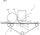
- FIG. 1 A solidification system 1 according to the prior art is shown, which essentially comprises an endless belt 7 or alternatively a drum with at least one water bar 4.
- the endless belt 7 can be designed as a sieve belt to drain the water quickly.
- a suction pipe 3b is shown as a rectangular box, which likewise has at least one suction slot 3c.
- the compacting plate 14 can be arranged directly on the water bar 4 and be attached.
- the attachment 15 in the area of the rear edge of the compacting plate 14 can be carried out on a side wall of the water bar 4, or of course also on the lower surface in the area of the nozzles 5. This has the advantage that the outlet edge 14a is very well aligned with the water jet 6 can be.
- the lateral attachment 15 to the water bar 4 can also have a height adjustment, among other things, so that the pressure on the fiber web 2 can be adjusted via the spring action of the straight or curved compacting plate 14.
- the fibrous web 2 is transported from left to right.
- the compacting is carried out by the compacting plate 14 close to the water jet 6, which prevents the fiber web 2 from being sucked in larger areas in front of the row of water jets 6 or from the vacuum into the suction pipe 3b and the fiber web from becoming entangled deformed in the process.
- the compacting plate 14 can increase the strength in the longitudinal direction of the fibrous web 2 due to the compacting action shortly before solidification by the water jets 6, since the trailing edge 14a only slides over the surface of the fibrous web 2. In contrast, there is no change in the orientation of the fibers over the entire cross section of the fiber web 2. Only the portion or strip of the fiber web 2 between the compacting plate 14 and the water jets 6 is stretched and the fibers are intertwined. At high speeds, the air entrained by the fiber web 2 builds up on the compacting plate 14. As a result, part of the air flow is laterally deflected by the endless belt 7. Another part of the air flow penetrates through the fiber web 2, builds up and creates warps in the fiber web 2, which can lift off the endless belt 7 shortly before the compacting plate 14.
- the invention provides for the air flow to be discharged above and / or below the fiber web 2 or derive.
- a discharge device for removing or discharging the entrained air can be arranged in front of or below the compacting plate 14.
- the discharge device can be designed as a roller with at least one opening through which the air is discharged laterally.
- the roller can simultaneously compact the fiber web 2 on the endless belt 7 or on a drum.
- the diverter can also be arranged and designed below the compacting plate to diverge the air flow.
- a vacuum can preferably be applied to the discharge device, or it can be designed in terms of flow technology so that a vacuum is formed at the inlet opening of the discharge device.
- the discharge device in the area of a storage belt in front of the endless belt 7 or the drum 3, if the space conditions here are such that the air flow can be carried away cheaply to the side or above the system. Care must be taken to ensure that a new air flow does not form behind the discharge device.
- an arrangement of the discharge device at a maximum distance of 2 m in front of the compacting plate can be useful, regardless of whether in the area of the same endless belt 7 or an upstream component, not shown.
- a discharge device in the form of a suction device is arranged above the endless belt 7 directly in front of the compacting plate 14 and is designed as a roller 8 20.
- the roller 8 has a multiplicity of openings which are distributed over the circumference of the cylinder jacket, into which the air flow penetrates and is discharged laterally. If the roller 8 is to be vacuumed, it is designed as a suction roller 22 and is subjected to a slight negative pressure of up to 0.3 bar (0.7 bar absolute) and diverts the air flow carried along by the fiber web 2.
- the roller 8 or Suction roller 20 can be arranged above the fibrous web 2 with a small gap of 0.5 to 5 mm and can exert no pressure on the fibrous web 2. In this embodiment, the roller 8 or suction roller 20 is not driven and is therefore stationary. It can be arranged to be pivotable in order to facilitate the start-up of the system and to facilitate maintenance work on the water bar 4.
- roller 8 or suction roller 20 can compact the fiber web 2 with the endless belt 7.
- a pressure roller 21 can be arranged below the endless belt 7, which compacted the fiber web 2 together with the roller 8 or suction roller 20.
- the roller 8 or suction roller 20 rests on the fibrous web 2 with the endless belt 7, counter pressure being generated by the pressure roller 21.
- Both rollers 8 or 20 and 21 rotate at the same peripheral speed, which preferably corresponds to the transport speed of the fiber web, so as not to produce any distortion.
- a deflection roller of the endless belt 7 can also be used, provided that it is arranged close to the area of the compacting plate 14.
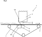
- Figure 2 shows the distance X between the discharge device (roller 8 or suction roller 20) and the outlet edge 14a of the compacting plate 14, which is a maximum of 2 m.
- the roller 8 or suction roller 20 is designed as a rotating compacting roller which, together with the endless belt 7, compresses the fiber web 2.
- the peripheral speed of the roller 8 or suction roller 20 is preferably identical to the transport speed of the fibrous web 2.
- the roller 8 or suction roller 20 is designed such that it can be pivoted below the horizontal plane of the endless belt 7 and thus a pressure on it the fiber web 2 and the endless belt 7 exercises.
- Figure 4 shows a diverter of the air flow above the fiber web 2, in which a suction hood 22 is arranged above the endless belt 7 and discharges the air flow entrained with the fiber web 2.
- the suction hood 22 is essentially designed in cross section as a cylindrical tube that extends over the working width of the endless belt 7. Along the longitudinal axis of the suction hood 22, the jacket of the tube is slit open and bent to an opening, so that here a larger diameter results than the original inner diameter.
- the opening of the suction hood 22 also extends over the entire working width of the endless belt and absorbs the air flow entrained by the fiber web 2.
- the suction hood 22 can advantageously be set at a distance from the endless belt and rotated around the suspension point in order to position the opening for the air flow.
- several suction hoods 22 can be arranged one behind the other in front of the water bar 4, it being possible for the arrangement to be at offset distances from the fiber web 2.
- the at least one suction hood 22 can also be actively vacuumed.
- Figure 5 shows a discharge device in the form of a suction box 23, which is arranged below the endless belt 7 below the compacting plate 14 and can be provided separately from the suction pipe 3b for the water jets 6 with a negative pressure ( ⁇ p). Since the air flow entrained by the fiber web 2 accumulates in front of the compacting plate 14 and at least partially flows through the fiber web 2 and the endless belt 7, the suction box 23 generates an alignment of the air flow with its negative pressure, with which the fiber web 2 without warping on the endless belt 7 remains.
- the suction box 23 is separated from the suction pipe 3b, whereby the water and the air can be discharged separately.
- this embodiment shows a suction opening 23a arranged obliquely to the endless belt 7, into which the air flow flowing through the fiber web runs vertically.
- This variant is particularly suitable for retrofitting under an existing consolidation system 1.
- Figure 6 shows a suction opening 3d for the air flow flowing through the fiber web 2, which is integrated in the suction pipe 3b.
- the suction opening 3d is arranged in front of the compacting plate 14 in the working direction and can have a suction independent of the suction slot 3c.
- FIG. 7 shows an embodiment with a vacuumed drum 3.
- the drum 3 can be designed as a so-called sieve drum, comprising a perforated plate drum, which is covered with a support fabric and a fine sieve or alternatively with a microporous shell.
- the drum can be designed as a structure drum, the surface of which has a perforation in order to give the fiber web 2 a structure or a pattern.
- the drum 3 has a multiplicity of bores 3a, through which the water of the water bar 4 is discharged.
- a suction pipe 3b with a multiplicity of suction slots 3c Arranged inside the drum 3 is a suction pipe 3b with a multiplicity of suction slots 3c, via which the water is sucked off under reduced pressure.
- the water bar 4 is arranged above the drum 3 and sprays a series of water jets 6 onto the fiber web 2 under high pressure by means of a plurality of nozzles 5.
- the water bar 4 is operated at a pressure of 10 to 100 bar, preferably at a pressure of 20 to 40 bar.
- the nozzle bar 4 can be operated with one or more rows of water jets 6.
- the nozzles 5 are arranged along the longitudinal axis of the water bar 4. Because of Only a number of water jets 6 are shown for clarity.
- the fibrous web 2 runs in the direction of the arrow from left to right over the drum 3 and is continuously hit by the water jets 6.
- the water bar 4 is arranged adjustable at a distance from the drum 3 or the endless web.
- the compacting plate 14 can be fastened to a rotatable suspension 11 with which the compacting plate 14 can be retrofitted into an existing system.
- a discharge device in the form of a suction box 23, the contour of which adjusts to the course of the fiber web 2 with the suction opening 23a.
- the outer wall assigned to the drum 3 can also be designed with a contour. In this case, the air flow resulting from the transport speed of the fiber web 2 is sucked off through the suction box 23, so that the fiber web 2 is not thrown up in front of the compacting plate 14. Except for the embodiment of Figure 6 all described and illustrated variants of a discharge of the air flow arranged above or below are also possible with the drum 3.
Landscapes
- Engineering & Computer Science (AREA)
- Textile Engineering (AREA)
- Nonwoven Fabrics (AREA)
Claims (13)
- Dispositif pour la consolidation hydrodynamique des non-tissés, des tissus tissés ou tricotés, comportant une installation de consolidation (1) ayant au moins une rampe d'eau (4) et un tambour (3) ou une bande sans fin (7), entre lesquels une nappe de fibres (2) est transportée et consolidée, dans lequel dans la direction de défilement de la nappe de fibres (2) en amont de la rampe d'eau (4), une tôle de compactage (14) est agencée, laquelle consolide la nappe de fibres (2) sur le tambour (3) ou sur la bande sans fin (7), caractérisé en ce que, en direction de défilement de la nappe de fibres (2) en amont de la tôle de compactage (14), au moins un dispositif de dérivation est agencé en-dessus et/ou en-dessous de la nappe de fibres (2), par l'intermédiaire duquel dispositif l'air entraîné par la nappe de fibres (2) est dérivé.
- Dispositif selon la revendication 1, caractérisé en ce que ledit au moins un dispositif de dérivation est aménagé comme rouleau (8), lequel comprend au moins une ouverture pour dériver l'air entraîné.
- Dispositif selon la revendication 2, caractérisé en ce que ledit au moins un dispositif de dérivation comprend une perforation ou est aménagé comme rouleau à tôle perforée.
- Dispositif selon l'une des revendications précédentes, caractérisé en ce que ledit au moins un dispositif de dérivation est agencé en-dessus de la nappe de fibres (2) et coopère avec la bande sans fin (7) ou un rouleau de pression (21) ou un rouleau déflecteur pour la bande sans fin (7) et est aménagé à compacter la nappe de fibres (2).
- Dispositif selon l'une des revendications 1 à 4, caractérisé en ce que ledit au moins un dispositif de dérivation est aménagé comme rouleau d'aspiration (20).
- Dispositif selon la revendication 5, caractérisé en ce que le rouleau (8), respectivement le rouleau d'aspiration (20) est agencé de façon espacée de la nappe de fibres (2).
- Dispositif selon la revendication 1 ou 2, caractérisé en ce que ledit au moins un dispositif de dérivation est aménagé comme hotte d'aspiration (22), dans laquelle le flux d'air entraîné par la nappe de fibres (2) entre tangentiellement.
- Dispositif selon la revendication 1, caractérisé en ce que ledit au moins un dispositif de dérivation est aménagé comme boîte d'aspiration (23), laquelle est agencée en-dessous de la nappe de fibres (2) et laquelle exerce une pression négative sur la nappe de fibres (2).
- Dispositif selon la revendication 1, caractérisé en ce que ledit au moins un dispositif de dérivation est aménagé comme ouverture d'aspiration (3d), laquelle est intégrée dans le tuyau d'aspiration (3b) pour les jets d'eau (6).
- Dispositif selon la revendication 8, caractérisé en ce que ladite au moins une boîte d'aspiration (23) comprend au moins une face extérieure, laquelle s'adapte au contour du tambour (3) et/ou à la course de la nappe de fibres (2).
- Dispositif selon l'une des revendications précédentes, caractérisé en ce que ladite au moins une aspiration (3d, 20, 22, 23) est aspirable à une pression négative jusqu'à concurrence de 0,3 bar.
- Dispositif selon l'une des revendications précédentes, caractérisé en ce que, en direction de travail, ledit au moins un dispositif de dérivation est agencé directement en amont de la tôle de compactage (14).
- Dispositif selon la revendication 11, caractérisé en ce que la distance (X) est au maximum de 2 m entre ledit au moins un dispositif de dérivation et le bord de sortie (14a) de la tôle de compactage (14) en direction de transport de la nappe de fibres (2).
Applications Claiming Priority (1)
| Application Number | Priority Date | Filing Date | Title |
|---|---|---|---|
| DE102017129220.9A DE102017129220A1 (de) | 2017-12-08 | 2017-12-08 | Vorrichtung zum hydrodynamischen Verfestigen von Vliesen, Geweben oder Gewirken |
Publications (2)
| Publication Number | Publication Date |
|---|---|
| EP3495544A1 EP3495544A1 (fr) | 2019-06-12 |
| EP3495544B1 true EP3495544B1 (fr) | 2020-02-05 |
Family
ID=63840688
Family Applications (1)
| Application Number | Title | Priority Date | Filing Date |
|---|---|---|---|
| EP18200089.3A Active EP3495544B1 (fr) | 2017-12-08 | 2018-10-12 | Dispositif d'aiguilletage hydrodynamique de non-tissés, tissus ou tricots |
Country Status (3)
| Country | Link |
|---|---|
| EP (1) | EP3495544B1 (fr) |
| CN (1) | CN109898233B (fr) |
| DE (1) | DE102017129220A1 (fr) |
Families Citing this family (2)
| Publication number | Priority date | Publication date | Assignee | Title |
|---|---|---|---|---|
| CN112301579B (zh) * | 2020-10-21 | 2023-12-22 | 江苏昱昊新材料有限公司 | 一种可控制水量的无纺布加工用打湿装置 |
| CN112609337B (zh) * | 2020-12-31 | 2024-07-02 | 龙南小麦自动化科技有限公司 | 一种熔喷布高压水刺设备 |
Family Cites Families (10)
| Publication number | Priority date | Publication date | Assignee | Title |
|---|---|---|---|---|
| FR2845698B1 (fr) * | 2002-10-11 | 2005-03-18 | Rieter Perfojet | Procede et installation de production d'un non-tisse ayant de bonnes proprietes de resistance a la traction |
| DE102005033070A1 (de) * | 2005-07-15 | 2007-01-25 | Fleissner Gmbh | Vorrichtung zum Verfestigen einer Faserbahn mit Druckwasserstrahlen |
| DE102006030803A1 (de) * | 2005-09-03 | 2007-03-15 | Fleissner Gmbh | Absaugkammer für einen Wasserbalken zur Strahlbeaufschlagung von Geweben |
| US20100159775A1 (en) * | 2008-12-19 | 2010-06-24 | Chambers Jr Leon Eugene | Nonwoven Composite And Method For Making The Same |
| CN101858015A (zh) * | 2009-04-08 | 2010-10-13 | 欧瑞康纺织有限及两合公司 | 用于纤维网干法成形的方法和设备 |
| DE102013101431B4 (de) | 2013-02-13 | 2016-06-23 | TRüTZSCHLER GMBH & CO. KG | Vorrichtung und Verfahren zum hydrodynamischen Verfestigen von Vliesen, Geweben und Gewirken |
| DE102013110915A1 (de) * | 2013-10-01 | 2015-04-02 | Trützschler GmbH & Co Kommanditgesellschaft | Vorverdichter zum Glätten bzw. Kompaktieren eines Faserbandes in einer Wickelmaschine, Wickelmaschine und Verfahren zum Betreiben einer Wickelmaschine |
| DE102015111340A1 (de) * | 2015-07-14 | 2017-01-19 | TRüTZSCHLER GMBH & CO. KG | Anlage und Verfahren zur Herstellung eines mehrschichtigen Vlieses aus mindestens einem unverfestigtem Faserflor |
| CN105970657B (zh) * | 2016-06-30 | 2018-01-05 | 山东大学 | 一种用于汽车内饰表皮的水刺再生革的制备方法 |
| CN107022842A (zh) * | 2017-05-08 | 2017-08-08 | 大连华纶无纺设备工程有限公司 | 双模头复合交络双组份纺粘水刺无纺布生产设备及生产工艺 |
-
2017
- 2017-12-08 DE DE102017129220.9A patent/DE102017129220A1/de not_active Withdrawn
-
2018
- 2018-10-12 EP EP18200089.3A patent/EP3495544B1/fr active Active
- 2018-10-29 CN CN201811266352.6A patent/CN109898233B/zh active Active
Non-Patent Citations (1)
| Title |
|---|
| None * |
Also Published As
| Publication number | Publication date |
|---|---|
| EP3495544A1 (fr) | 2019-06-12 |
| DE102017129220A1 (de) | 2019-06-13 |
| CN109898233B (zh) | 2022-04-01 |
| CN109898233A (zh) | 2019-06-18 |
Similar Documents
| Publication | Publication Date | Title |
|---|---|---|
| EP3118361B1 (fr) | Installation et procede de fabrication d'un voile multicouche a partir d'au moins un voile de carde non encolle | |
| DE29521570U1 (de) | Vorrichtung zum Herstellen eines nicht-gewebten textilen Tuches mittels Druckwasserstrahlen | |
| DE4327601C1 (de) | Vorrichtung zum Reinigen eines umlaufenden Siebes | |
| EP3495544B1 (fr) | Dispositif d'aiguilletage hydrodynamique de non-tissés, tissus ou tricots | |
| DE102008008549A1 (de) | Vorrichtung zum Herstellen und Verfestigen eines reinen Spinnvlieses | |
| EP3495543B1 (fr) | Installation et procédé de fabrication d'un tissu non-tissé | |
| WO2010115400A1 (fr) | Dispositif pour consolider une nappe de fibres | |
| EP0522093B1 (fr) | Procede et dispositif pour le nettoyage d'une toile sans fin de machine a papier | |
| EP2956578B1 (fr) | Dispositif et procédé permettant la consolidation hydrodynamique de non-tissés, de tissus et de tricots | |
| EP1876278A1 (fr) | Chambre d'aspiration pour une rampe d'eau destinée au traitement de tissus par jet d' eau | |
| DE3400939C2 (fr) | ||
| EP1873290B1 (fr) | Chambre d'aspiration pour une rampe d'eau destinée à traiter des tissus par aguilletage hydraulique | |
| EP4067548A1 (fr) | Installation de consolidation des couches comprenant des fibres en une bande de non-tissée | |
| DE10321283B4 (de) | Vliesmaschine | |
| EP2539498B1 (fr) | Dispositif de consolidation d'une bande de matériau | |
| EP1760180A2 (fr) | Chambre d'aspiration pour un distributeur pour le traitement par jets d'eau de tissus | |
| EP4067549B1 (fr) | Installation et procédé de consolidation des couches comprenant des fibres en une bande de non-tissé | |
| EP1842960B1 (fr) | Procédé et dispositif destinés au nettoyage d'une surface d'une bande mobile | |
| DE102008052706A1 (de) | Vorrichtung zur Wasserstrahlbeaufschlagung | |
| EP2508672B1 (fr) | Dispositif destiné au transfert d'un bande dans une station d'une machine de fabrication de bandes ou de traitement | |
| EP3536841B1 (fr) | Installation et procédé de production d'un velours textile | |
| DE102009032343A1 (de) | Vorrichtung zum Verfestigen einer Materialbahn | |
| DE102020134721A1 (de) | Vorrichtung zur Herstellung einer Verbundvlieswarenbahn | |
| EP2508675B1 (fr) | Dispositif destiné au transfert d'une bande dans une machine de fabrication ou de traitement de matériau en bande | |
| DE102021111469A1 (de) | Anlage und Verfahren zur Herstellung einer fluidstrahlvernadelten Faserstoffbahn aus mindestens einer Faserstoffsuspension |
Legal Events
| Date | Code | Title | Description |
|---|---|---|---|
| PUAI | Public reference made under article 153(3) epc to a published international application that has entered the european phase |
Free format text: ORIGINAL CODE: 0009012 |
|
| STAA | Information on the status of an ep patent application or granted ep patent |
Free format text: STATUS: REQUEST FOR EXAMINATION WAS MADE |
|
| 17P | Request for examination filed |
Effective date: 20181012 |
|
| AK | Designated contracting states |
Kind code of ref document: A1 Designated state(s): AL AT BE BG CH CY CZ DE DK EE ES FI FR GB GR HR HU IE IS IT LI LT LU LV MC MK MT NL NO PL PT RO RS SE SI SK SM TR |
|
| AX | Request for extension of the european patent |
Extension state: BA ME |
|
| GRAP | Despatch of communication of intention to grant a patent |
Free format text: ORIGINAL CODE: EPIDOSNIGR1 |
|
| STAA | Information on the status of an ep patent application or granted ep patent |
Free format text: STATUS: GRANT OF PATENT IS INTENDED |
|
| INTG | Intention to grant announced |
Effective date: 20191011 |
|
| GRAS | Grant fee paid |
Free format text: ORIGINAL CODE: EPIDOSNIGR3 |
|
| GRAA | (expected) grant |
Free format text: ORIGINAL CODE: 0009210 |
|
| STAA | Information on the status of an ep patent application or granted ep patent |
Free format text: STATUS: THE PATENT HAS BEEN GRANTED |
|
| RBV | Designated contracting states (corrected) |
Designated state(s): AL AT BE BG CH CY CZ DE DK EE ES FI FR GB GR HR HU IE IS IT LI LT LU LV MC MK MT NL NO PL PT RO RS SE SI SK SM TR |
|
| AK | Designated contracting states |
Kind code of ref document: B1 Designated state(s): AL AT BE BG CH CY CZ DE DK EE ES FI FR GB GR HR HU IE IS IT LI LT LU LV MC MK MT NL NO PL PT RO RS SE SI SK SM TR |
|
| REG | Reference to a national code |
Ref country code: GB Ref legal event code: FG4D Free format text: NOT ENGLISH |
|
| REG | Reference to a national code |
Ref country code: AT Ref legal event code: REF Ref document number: 1229964 Country of ref document: AT Kind code of ref document: T Effective date: 20200215 |
|
| REG | Reference to a national code |
Ref country code: DE Ref legal event code: R096 Ref document number: 502018000725 Country of ref document: DE |
|
| REG | Reference to a national code |
Ref country code: IE Ref legal event code: FG4D Free format text: LANGUAGE OF EP DOCUMENT: GERMAN |
|
| REG | Reference to a national code |
Ref country code: CH Ref legal event code: EP |
|
| REG | Reference to a national code |
Ref country code: NL Ref legal event code: MP Effective date: 20200205 |
|
| PG25 | Lapsed in a contracting state [announced via postgrant information from national office to epo] |
Ref country code: NO Free format text: LAPSE BECAUSE OF FAILURE TO SUBMIT A TRANSLATION OF THE DESCRIPTION OR TO PAY THE FEE WITHIN THE PRESCRIBED TIME-LIMIT Effective date: 20200505 Ref country code: PT Free format text: LAPSE BECAUSE OF FAILURE TO SUBMIT A TRANSLATION OF THE DESCRIPTION OR TO PAY THE FEE WITHIN THE PRESCRIBED TIME-LIMIT Effective date: 20200628 Ref country code: RS Free format text: LAPSE BECAUSE OF FAILURE TO SUBMIT A TRANSLATION OF THE DESCRIPTION OR TO PAY THE FEE WITHIN THE PRESCRIBED TIME-LIMIT Effective date: 20200205 Ref country code: FI Free format text: LAPSE BECAUSE OF FAILURE TO SUBMIT A TRANSLATION OF THE DESCRIPTION OR TO PAY THE FEE WITHIN THE PRESCRIBED TIME-LIMIT Effective date: 20200205 |
|
| REG | Reference to a national code |
Ref country code: LT Ref legal event code: MG4D |
|
| PG25 | Lapsed in a contracting state [announced via postgrant information from national office to epo] |
Ref country code: GR Free format text: LAPSE BECAUSE OF FAILURE TO SUBMIT A TRANSLATION OF THE DESCRIPTION OR TO PAY THE FEE WITHIN THE PRESCRIBED TIME-LIMIT Effective date: 20200506 Ref country code: HR Free format text: LAPSE BECAUSE OF FAILURE TO SUBMIT A TRANSLATION OF THE DESCRIPTION OR TO PAY THE FEE WITHIN THE PRESCRIBED TIME-LIMIT Effective date: 20200205 Ref country code: BG Free format text: LAPSE BECAUSE OF FAILURE TO SUBMIT A TRANSLATION OF THE DESCRIPTION OR TO PAY THE FEE WITHIN THE PRESCRIBED TIME-LIMIT Effective date: 20200505 Ref country code: LV Free format text: LAPSE BECAUSE OF FAILURE TO SUBMIT A TRANSLATION OF THE DESCRIPTION OR TO PAY THE FEE WITHIN THE PRESCRIBED TIME-LIMIT Effective date: 20200205 Ref country code: IS Free format text: LAPSE BECAUSE OF FAILURE TO SUBMIT A TRANSLATION OF THE DESCRIPTION OR TO PAY THE FEE WITHIN THE PRESCRIBED TIME-LIMIT Effective date: 20200605 Ref country code: SE Free format text: LAPSE BECAUSE OF FAILURE TO SUBMIT A TRANSLATION OF THE DESCRIPTION OR TO PAY THE FEE WITHIN THE PRESCRIBED TIME-LIMIT Effective date: 20200205 |
|
| PG25 | Lapsed in a contracting state [announced via postgrant information from national office to epo] |
Ref country code: NL Free format text: LAPSE BECAUSE OF FAILURE TO SUBMIT A TRANSLATION OF THE DESCRIPTION OR TO PAY THE FEE WITHIN THE PRESCRIBED TIME-LIMIT Effective date: 20200205 |
|
| PG25 | Lapsed in a contracting state [announced via postgrant information from national office to epo] |
Ref country code: RO Free format text: LAPSE BECAUSE OF FAILURE TO SUBMIT A TRANSLATION OF THE DESCRIPTION OR TO PAY THE FEE WITHIN THE PRESCRIBED TIME-LIMIT Effective date: 20200205 Ref country code: CZ Free format text: LAPSE BECAUSE OF FAILURE TO SUBMIT A TRANSLATION OF THE DESCRIPTION OR TO PAY THE FEE WITHIN THE PRESCRIBED TIME-LIMIT Effective date: 20200205 Ref country code: ES Free format text: LAPSE BECAUSE OF FAILURE TO SUBMIT A TRANSLATION OF THE DESCRIPTION OR TO PAY THE FEE WITHIN THE PRESCRIBED TIME-LIMIT Effective date: 20200205 Ref country code: SK Free format text: LAPSE BECAUSE OF FAILURE TO SUBMIT A TRANSLATION OF THE DESCRIPTION OR TO PAY THE FEE WITHIN THE PRESCRIBED TIME-LIMIT Effective date: 20200205 Ref country code: DK Free format text: LAPSE BECAUSE OF FAILURE TO SUBMIT A TRANSLATION OF THE DESCRIPTION OR TO PAY THE FEE WITHIN THE PRESCRIBED TIME-LIMIT Effective date: 20200205 Ref country code: LT Free format text: LAPSE BECAUSE OF FAILURE TO SUBMIT A TRANSLATION OF THE DESCRIPTION OR TO PAY THE FEE WITHIN THE PRESCRIBED TIME-LIMIT Effective date: 20200205 Ref country code: SM Free format text: LAPSE BECAUSE OF FAILURE TO SUBMIT A TRANSLATION OF THE DESCRIPTION OR TO PAY THE FEE WITHIN THE PRESCRIBED TIME-LIMIT Effective date: 20200205 Ref country code: EE Free format text: LAPSE BECAUSE OF FAILURE TO SUBMIT A TRANSLATION OF THE DESCRIPTION OR TO PAY THE FEE WITHIN THE PRESCRIBED TIME-LIMIT Effective date: 20200205 |
|
| REG | Reference to a national code |
Ref country code: DE Ref legal event code: R097 Ref document number: 502018000725 Country of ref document: DE |
|
| PLBE | No opposition filed within time limit |
Free format text: ORIGINAL CODE: 0009261 |
|
| STAA | Information on the status of an ep patent application or granted ep patent |
Free format text: STATUS: NO OPPOSITION FILED WITHIN TIME LIMIT |
|
| 26N | No opposition filed |
Effective date: 20201106 |
|
| PG25 | Lapsed in a contracting state [announced via postgrant information from national office to epo] |
Ref country code: PL Free format text: LAPSE BECAUSE OF FAILURE TO SUBMIT A TRANSLATION OF THE DESCRIPTION OR TO PAY THE FEE WITHIN THE PRESCRIBED TIME-LIMIT Effective date: 20200205 |
|
| PG25 | Lapsed in a contracting state [announced via postgrant information from national office to epo] |
Ref country code: LU Free format text: LAPSE BECAUSE OF NON-PAYMENT OF DUE FEES Effective date: 20201012 Ref country code: MC Free format text: LAPSE BECAUSE OF FAILURE TO SUBMIT A TRANSLATION OF THE DESCRIPTION OR TO PAY THE FEE WITHIN THE PRESCRIBED TIME-LIMIT Effective date: 20200205 |
|
| REG | Reference to a national code |
Ref country code: BE Ref legal event code: MM Effective date: 20201031 |
|
| PG25 | Lapsed in a contracting state [announced via postgrant information from national office to epo] |
Ref country code: BE Free format text: LAPSE BECAUSE OF NON-PAYMENT OF DUE FEES Effective date: 20201031 |
|
| PG25 | Lapsed in a contracting state [announced via postgrant information from national office to epo] |
Ref country code: IE Free format text: LAPSE BECAUSE OF NON-PAYMENT OF DUE FEES Effective date: 20201012 |
|
| REG | Reference to a national code |
Ref country code: CH Ref legal event code: PL |
|
| PG25 | Lapsed in a contracting state [announced via postgrant information from national office to epo] |
Ref country code: TR Free format text: LAPSE BECAUSE OF FAILURE TO SUBMIT A TRANSLATION OF THE DESCRIPTION OR TO PAY THE FEE WITHIN THE PRESCRIBED TIME-LIMIT Effective date: 20200205 Ref country code: MT Free format text: LAPSE BECAUSE OF FAILURE TO SUBMIT A TRANSLATION OF THE DESCRIPTION OR TO PAY THE FEE WITHIN THE PRESCRIBED TIME-LIMIT Effective date: 20200205 Ref country code: CY Free format text: LAPSE BECAUSE OF FAILURE TO SUBMIT A TRANSLATION OF THE DESCRIPTION OR TO PAY THE FEE WITHIN THE PRESCRIBED TIME-LIMIT Effective date: 20200205 |
|
| PG25 | Lapsed in a contracting state [announced via postgrant information from national office to epo] |
Ref country code: MK Free format text: LAPSE BECAUSE OF FAILURE TO SUBMIT A TRANSLATION OF THE DESCRIPTION OR TO PAY THE FEE WITHIN THE PRESCRIBED TIME-LIMIT Effective date: 20200205 Ref country code: AL Free format text: LAPSE BECAUSE OF FAILURE TO SUBMIT A TRANSLATION OF THE DESCRIPTION OR TO PAY THE FEE WITHIN THE PRESCRIBED TIME-LIMIT Effective date: 20200205 |
|
| REG | Reference to a national code |
Ref country code: AT Ref legal event code: PC Ref document number: 1229964 Country of ref document: AT Kind code of ref document: T Owner name: TRUETZSCHLER GROUP SE, DE Effective date: 20220516 |
|
| REG | Reference to a national code |
Ref country code: DE Ref legal event code: R081 Ref document number: 502018000725 Country of ref document: DE Owner name: TRUETZSCHLER GROUP SE, DE Free format text: FORMER OWNER: TRUETZSCHLER GMBH & CO. KG, 41199 MOENCHENGLADBACH, DE |
|
| PG25 | Lapsed in a contracting state [announced via postgrant information from national office to epo] |
Ref country code: LI Free format text: LAPSE BECAUSE OF NON-PAYMENT OF DUE FEES Effective date: 20211031 Ref country code: CH Free format text: LAPSE BECAUSE OF NON-PAYMENT OF DUE FEES Effective date: 20211031 |
|
| GBPC | Gb: european patent ceased through non-payment of renewal fee |
Effective date: 20221012 |
|
| P01 | Opt-out of the competence of the unified patent court (upc) registered |
Effective date: 20230622 |
|
| PG25 | Lapsed in a contracting state [announced via postgrant information from national office to epo] |
Ref country code: SI Free format text: LAPSE BECAUSE OF FAILURE TO SUBMIT A TRANSLATION OF THE DESCRIPTION OR TO PAY THE FEE WITHIN THE PRESCRIBED TIME-LIMIT Effective date: 20200205 |
|
| PG25 | Lapsed in a contracting state [announced via postgrant information from national office to epo] |
Ref country code: GB Free format text: LAPSE BECAUSE OF NON-PAYMENT OF DUE FEES Effective date: 20221012 |
|
| PGFP | Annual fee paid to national office [announced via postgrant information from national office to epo] |
Ref country code: IT Payment date: 20231026 Year of fee payment: 6 Ref country code: FR Payment date: 20231026 Year of fee payment: 6 Ref country code: DE Payment date: 20231020 Year of fee payment: 6 Ref country code: AT Payment date: 20231020 Year of fee payment: 6 |