EP3495150B1 - Kopfspannungskorrekturverfahren für tintenstrahlvorrichtung, vorrichtung mit verwendung davon und programm dafür - Google Patents
Kopfspannungskorrekturverfahren für tintenstrahlvorrichtung, vorrichtung mit verwendung davon und programm dafür Download PDFInfo
- Publication number
- EP3495150B1 EP3495150B1 EP18210335.8A EP18210335A EP3495150B1 EP 3495150 B1 EP3495150 B1 EP 3495150B1 EP 18210335 A EP18210335 A EP 18210335A EP 3495150 B1 EP3495150 B1 EP 3495150B1
- Authority
- EP
- European Patent Office
- Prior art keywords
- head module
- density
- band
- satellite
- drive voltage
- Prior art date
- Legal status (The legal status is an assumption and is not a legal conclusion. Google has not performed a legal analysis and makes no representation as to the accuracy of the status listed.)
- Active
Links
Images


Classifications
-
- B—PERFORMING OPERATIONS; TRANSPORTING
- B41—PRINTING; LINING MACHINES; TYPEWRITERS; STAMPS
- B41J—TYPEWRITERS; SELECTIVE PRINTING MECHANISMS, i.e. MECHANISMS PRINTING OTHERWISE THAN FROM A FORME; CORRECTION OF TYPOGRAPHICAL ERRORS
- B41J29/00—Details of, or accessories for, typewriters or selective printing mechanisms not otherwise provided for
- B41J29/38—Drives, motors, controls or automatic cut-off devices for the entire printing mechanism
- B41J29/393—Devices for controlling or analysing the entire machine ; Controlling or analysing mechanical parameters involving printing of test patterns
-
- B—PERFORMING OPERATIONS; TRANSPORTING
- B41—PRINTING; LINING MACHINES; TYPEWRITERS; STAMPS
- B41J—TYPEWRITERS; SELECTIVE PRINTING MECHANISMS, i.e. MECHANISMS PRINTING OTHERWISE THAN FROM A FORME; CORRECTION OF TYPOGRAPHICAL ERRORS
- B41J2/00—Typewriters or selective printing mechanisms characterised by the printing or marking process for which they are designed
- B41J2/005—Typewriters or selective printing mechanisms characterised by the printing or marking process for which they are designed characterised by bringing liquid or particles selectively into contact with a printing material
- B41J2/01—Ink jet
- B41J2/21—Ink jet for multi-colour printing
- B41J2/2132—Print quality control characterised by dot disposition, e.g. for reducing white stripes or banding
- B41J2/2146—Print quality control characterised by dot disposition, e.g. for reducing white stripes or banding for line print heads
-
- B—PERFORMING OPERATIONS; TRANSPORTING
- B41—PRINTING; LINING MACHINES; TYPEWRITERS; STAMPS
- B41J—TYPEWRITERS; SELECTIVE PRINTING MECHANISMS, i.e. MECHANISMS PRINTING OTHERWISE THAN FROM A FORME; CORRECTION OF TYPOGRAPHICAL ERRORS
- B41J2/00—Typewriters or selective printing mechanisms characterised by the printing or marking process for which they are designed
- B41J2/005—Typewriters or selective printing mechanisms characterised by the printing or marking process for which they are designed characterised by bringing liquid or particles selectively into contact with a printing material
- B41J2/01—Ink jet
- B41J2/015—Ink jet characterised by the jet generation process
- B41J2/04—Ink jet characterised by the jet generation process generating single droplets or particles on demand
- B41J2/045—Ink jet characterised by the jet generation process generating single droplets or particles on demand by pressure, e.g. electromechanical transducers
- B41J2/04501—Control methods or devices therefor, e.g. driver circuits, control circuits
- B41J2/04516—Control methods or devices therefor, e.g. driver circuits, control circuits preventing formation of satellite drops
-
- B—PERFORMING OPERATIONS; TRANSPORTING
- B41—PRINTING; LINING MACHINES; TYPEWRITERS; STAMPS
- B41J—TYPEWRITERS; SELECTIVE PRINTING MECHANISMS, i.e. MECHANISMS PRINTING OTHERWISE THAN FROM A FORME; CORRECTION OF TYPOGRAPHICAL ERRORS
- B41J2/00—Typewriters or selective printing mechanisms characterised by the printing or marking process for which they are designed
- B41J2/005—Typewriters or selective printing mechanisms characterised by the printing or marking process for which they are designed characterised by bringing liquid or particles selectively into contact with a printing material
- B41J2/01—Ink jet
- B41J2/015—Ink jet characterised by the jet generation process
- B41J2/04—Ink jet characterised by the jet generation process generating single droplets or particles on demand
- B41J2/045—Ink jet characterised by the jet generation process generating single droplets or particles on demand by pressure, e.g. electromechanical transducers
- B41J2/04501—Control methods or devices therefor, e.g. driver circuits, control circuits
- B41J2/04558—Control methods or devices therefor, e.g. driver circuits, control circuits detecting presence or properties of a dot on paper
-
- G—PHYSICS
- G06—COMPUTING OR CALCULATING; COUNTING
- G06K—GRAPHICAL DATA READING; PRESENTATION OF DATA; RECORD CARRIERS; HANDLING RECORD CARRIERS
- G06K15/00—Arrangements for producing a permanent visual presentation of the output data, e.g. computer output printers
- G06K15/02—Arrangements for producing a permanent visual presentation of the output data, e.g. computer output printers using printers
- G06K15/027—Test patterns and calibration
-
- B—PERFORMING OPERATIONS; TRANSPORTING
- B41—PRINTING; LINING MACHINES; TYPEWRITERS; STAMPS
- B41J—TYPEWRITERS; SELECTIVE PRINTING MECHANISMS, i.e. MECHANISMS PRINTING OTHERWISE THAN FROM A FORME; CORRECTION OF TYPOGRAPHICAL ERRORS
- B41J29/00—Details of, or accessories for, typewriters or selective printing mechanisms not otherwise provided for
- B41J29/38—Drives, motors, controls or automatic cut-off devices for the entire printing mechanism
- B41J29/393—Devices for controlling or analysing the entire machine ; Controlling or analysing mechanical parameters involving printing of test patterns
- B41J2029/3935—Devices for controlling or analysing the entire machine ; Controlling or analysing mechanical parameters involving printing of test patterns by means of printed test patterns
Definitions
- This invention relates to a head voltage correcting method for inkjet printing apparatus which perform printing on a printing medium by dispensing ink droplets thereto, to an apparatus using the same, and to a program thereof.
- the invention relates to a technique of voltage correction in a head having a plurality of head modules arranged in a direction perpendicular to a printing medium transport direction, each head module having a plurality of nozzles.
- An inkjet printing apparatus according to the preamble of claim 1 is known from JP 2013 244712 A .
- An inkjet printing apparatus performs printing by dispensing ink droplets from head modules to a printing medium. Since there are an individual difference from one head module to another and a question of print quality, adjustment is made at the time of manufacture to be capable of dispensing ink droplets in a predetermined density level which satisfies the specifications, and a voltage used at that time is set as reference voltage. Then, at the time of printing, the head modules are given a drive voltage shifted from the reference voltage according to the density of print data.
- the ink droplets may be in the form of main droplets and satellite droplets (also called mists) following the main droplets.
- Print quality will deteriorate particularly when excessive distances occur between the main droplets and satellite droplets. In order to inhibit the deterioration of print quality, therefore, an adjustment is made to lower the drive voltage for decreasing the satellite droplets (see Japanese Patent No. 4497825 , for example).
- a conventional head voltage correcting method for inkjet printing apparatus is executed as follows. Testing charts are first printed on printing paper, and the testing charts are read to correct a reference voltage. Specifically, droplet images including main droplets and satellite droplets are acquired, the lengths of the droplet images are obtained, and differences between these lengths and the length of an ideal droplet image are determined. Then the reference voltage is corrected to reduce the differences (see Japanese Unexamined Patent Publication No. 2016-2662 , for example).
- inkjet printing apparatus that includes a head having a plurality of head modules arranged in a direction perpendicular to a transport direction of printing paper to enable printing over a full width in the direction perpendicular to the transport direction of printing paper.
- the reference voltage noted above is set for each head module.
- the conventional method may adjust the reference voltage for the head modules to avoid occurrence of the satellite droplets in order to inhibit the deterioration of print quality. This poses a problem that, even if the adjustment is made for one head module, it may be impossible to make similar adjustment also for adjacent head modules to uniform density, or may require very complicated adjustment.
- This invention has been made having regard to the state of the art noted above, and its object is to provide a head voltage correcting method for inkjet printing apparatus, and an apparatus using the same, capable of easily uniforming ink droplet density for a plurality of head modules while inhibiting the deterioration of print quality, which is achieved by devising testing charts.
- This object is achieved by the subject-matters of the independent claims. Further advantageous embodiments of the invention are the subject-matter of the dependent claims. The invention is defined by the claims.
- An aspect of the invention provides a head voltage correcting method for inkjet printing apparatus which perform printing on a printing medium with a head having a plurality of head modules, each with a plurality of nozzles for dispensing ink droplets, the head modules being arranged in a direction perpendicular to a transport direction of the printing medium, the method comprising a testing chart printing step for printing testing charts on the printing medium, the testing charts including a lowest density head module check pattern printed by using, as a drive voltage, a reference voltage set beforehand for each of the head modules; satellite check patterns printed with respective drive voltages along the transport direction while changing the drive voltage at predetermined steps from the reference voltage for each of the head modules; band-by-band density variable patterns printed by one of the head modules, each by using a certain drive voltage over a predetermined length in the transport direction, which patterns being printed while changing the drive voltage at predetermined steps for each predetermined length in the transport direction; and in-band density variable patterns printed by a head module adjacent the one of the head modules, each of which patterns is
- a lowest density head module is determined out of a plurality of head modules by using the lowest density head module check pattern, a satellite-free drive voltage is determined based on this lowest density head module and satellite check patterns, and this drive voltage is set as a new reference voltage for the lowest density head module. Then, drive voltages corresponding to the in-band density variable patterns or band-by-band density variable patterns of the adjacent head module having density in agreement with the density by the satellite-free drive voltage of the in-band density variable patterns or band-by-band density variable patterns printed by the lowest density head module are set as new reference voltage for the adjacent head modules.
- drive voltage corresponding to the in-band density variable patterns or band-by-band density variable patterns of the further adjacent head module having density in agreement with the density by the new reference voltage of the band-by-band density variable patterns or in-band density variable patterns printed by the adjacent head module is set as a new reference voltage for the further adjacent head module.
- the satellite-free drive voltage which produces no satellite is made a reference voltage for the lowest density head module, and drive voltage of the adjacent and further adjacent head modules in agreement with the density by the reference voltage are made reference voltages.
- the adjacent head module and further adjacent head modules which are lower than that of the lowest density head module become reference voltages, the adjacent head module and further adjacent head module are also given drive voltages free from satellites.
- the density levels of ink droplets can easily be uniformed among the plurality of head modules, while inhibiting a deterioration of print quality.
- the method further comprises an image acquiring step executed after the testing chart printing step for acquiring testing pattern images by scanning the testing patterns; wherein the lowest density head module determining step, the satellite-free drive voltage determining step, and the new reference voltage determining step are executed by image processing of the testing pattern images.
- the lowest density head module check pattern is a solid of 60% target density by the reference voltage.
- the predetermined steps are set to -2% each from reference voltage 0%.
- the predetermined steps are too fine, efficiency will lower. When they are too rough, accuracy lowers.
- the predetermined steps of 2% can maintain good efficiency and yet appropriate accuracy.
- the band-by-band density variable patterns and the in-band density variable patterns of the testing charts are printed alternately in the direction perpendicular to the transport direction of the printing medium.
- an inkjet printing apparatus for printing on a printing medium by dispensing ink droplets thereto, the apparatus comprising a head including a plurality of head modules arranged in a direction perpendicular to a transport direction of the printing medium, each of the head modules having a plurality of nozzles for dispensing the ink droplets; a transporting device disposed in a position spaced from and opposed to the head for transporting the printing medium; and a printing controller for printing testing charts on the printing medium, the testing charts including a lowest density head module check pattern printed by using, as a drive voltage, a reference voltage set beforehand for each of the head modules; satellite check patterns printed with respective drive voltages along the transport direction while changing the drive voltage at predetermined steps from the reference voltage for each of the head modules; band-by-band density variable patterns printed by one of the head modules, each by using a certain drive voltage over a predetermined length in the transport direction, which patterns being printed while changing the drive voltage at predetermined steps for each predetermined length in the
- the printing controller has testing charts printed on the printing medium by dispensing ink droplets from the head while the printing medium is transported by the transporting device.
- a lowest density head module is determined out of a plurality of head modules by using the lowest density head module check pattern, a satellite-free drive voltage is determined based on this lowest density head module and satellite check patterns, and this drive voltage is set as a new reference voltage for the lowest density head module.
- drive voltages corresponding to the in-band density variable patterns or band-by-band density variable patterns of the adjacent head module having density in agreement with the density by the satellite-free drive voltage of the in-band density variable patterns or band-by-band density variable patterns printed by the lowest density head module are set as new reference voltage for the adjacent head modules.
- drive voltage corresponding to the in-band density variable patterns or band-by-band density variable patterns of the further adjacent head module having density in agreement with the density by the new reference voltage of the band-by-band density variable patterns or in-band density variable patterns printed by the adjacent head module is set as a new reference voltage for the further adjacent head module.
- the satellite-free drive voltage which produces no satellite is made a reference voltage for the lowest density head module, and drive voltage of the adjacent and further adjacent head modules in agreement with the density by the reference voltage are made reference voltages.
- the adjacent head module and further adjacent head modules which are lower than that of the lowest density head module become reference voltages, the adjacent head module and further adjacent head module are also given drive voltages free from satellites.
- the density levels of ink droplets can easily be uniformed among the plurality of head modules, while inhibiting a deterioration of print quality.
- the apparatus an image acquiring unit for acquiring testing pattern images by scanning the testing patterns printed on the printing medium; and a reference voltage determiner for determining the lowest density head module, the satellite-free drive voltage, and the new reference voltage by performing image processing of the testing pattern images.
- the reference voltage determiner for determines the lowest density head module and so on by performing image processing of the testing pattern images acquired by the image acquiring unit the processes are carried out efficiently and accurately.
- Fig. 1 is an outline schematic view showing an entire inkjet printing system according to the embodiment.
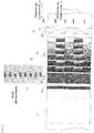
- Fig. 2 is a plan view of a head and web paper with testing charts printed thereon.
- the inkjet printing system includes a paper feeder 1, an inkjet printing apparatus 3 and a takeup roller 5.
- the paper feeder 1 holds web paper WP in a roll form to be rotatable about a horizontal axis, and unwinds and feeds the web paper WP to the inkjet printing apparatus 3.
- the inkjet printing apparatus 3 performs printing on the web paper WP.
- the takeup roller 5 takes up on a horizontal axis the web paper WP printed in the inkjet printing apparatus 3. Referring to the side of feeding the web paper WP as upstream and that of discharging the web paper WP as downstream, the paper feeder 1 is located upstream of the inkjet printing apparatus 3, and the takeup roller 5 downstream thereof.
- the inkjet printing apparatus 3 includes a drive roller 7 disposed in an upstream position for taking in the web paper WP from the paper feeder 1.
- the web paper WP unwound from the paper feeder 1 by the drive roller 7 is transported downstream along a plurality of transport rollers 9 toward the takeup roller 5.
- a drive roller 11 is disposed between the most downstream transport roller 9 and the takeup roller 5. This drive roller 11 feeds the web paper WP transported on the transport rollers 9 forward toward the takeup roller 5.
- the direction in which the web paper W is transported by the drive roller 7 and transport rollers 9 will be called herein the transport direction X.
- the inkjet printing apparatus 3 has a printing unit 13, a dryer 15 and a scanning unit 17 arranged in the stated order from upstream between the drive roller 7 and drive roller 11.
- the dryer 15 dries portions printed by the printing unit 13.
- the scanning unit 17 is a mechanism for reading the web paper WP (printing medium) printed by the printing unit 13, and acquires testing chart images for checking whether the printed portions have stains, omissions or other defects, and for correcting a reference voltage which will be described hereinafter.
- the printing unit 13 has heads 19 for dispensing ink droplets. It is common practice to provide a plurality of printing units 13 arranged along the transport direction of web paper WP. For example, four printing units 13 are provided separately for black (K), cyan (C), magenta (M), and yellow (Y). In this embodiment, description will be made assuming that only one printing unit 13 is provided, in order to facilitate understanding of the invention.
- the printing unit 13 includes heads 19 each with a plurality of nozzles just to be capable of printing without moving over a printing area transversely of the web paper WP (i.e. perpendicular to the plane of Fig. 1 , which is a direction perpendicular to the transport direction X, and will be referred to as the transverse direction Y).
- Each of these heads 19 has five head modules HM1-HM5, for example.
- the five head modules are arranged in the direction perpendicular to the transport direction X (i.e. in the transverse direction Y). That is, the inkjet printing apparatus 3 in this embodiment performs printing on the web paper WP while feeding the web paper WP in an auxiliary scanning direction relative to the head 19, with the heads 19 maintained stationary, not moving for main scans in the direction perpendicular to the transport direction of the web paper WP.
- Such a construction is called one-pass machine.
- the drive rollers 7 and 11, printing unit 13, dryer 15, and scanning unit 17 are controlled overall by a controller 21.
- the controller 21 includes a CPU, memory, and so on, and receives from outside print data including image information for printing on the web paper WP.
- the controller 21 carries out printing through the printing unit 13 by referring to reference voltages stored in a storage unit 23, and outputting drive voltages according to the print data to drivers 25.
- the controller 21 controls drive speed of the drive rollers 7 and 11 according to printing speed and ink droplet dispensation rate of the printing unit 13.
- the drivers 25 are provided as corresponding to the heads 19 of the printing unit 13. In this embodiment, therefore, since the number of heads 19 of the printing unit 13 is five, the number of drivers 25 is five.
- the controller 21 executes a program PG and the like to be described hereinafter to carry out various processes.
- the storage unit 23 stores a reference voltage set in a unit-by-unit adjustment stage for each head 19 carried out before shipment of the apparatus, for example.
- the reference voltage herein is a drive voltage applied to each driver 25, when printing by each head 19, so that the density of ink droplets agree with a specified density level.
- testing charts are printed with the heads 19 attached to the printing unit 13 of the inkjet printing apparatus 1, and the reference voltages in the storage unit 23 are updated and corrected with drive voltages obtained based on these testing charts.
- Each driver 25 operates the corresponding head 19 according to the drive voltage given from the controller 21.
- each head 19 includes a piezoelectric element extendible and contractible in response to the level of the voltage applied, and each driver 25 applies the drive voltage to the piezoelectric element.
- an area printed by a head 19 may include ink droplets forming, in terms of structure, main droplets D1 and satellite droplets D2 following the main droplets D1.
- the main droplets D1 and satellite droplets D2 may become indistinctively close together to appear integrated or leave only the main droplets D1.
- the scanning unit 17 has built therein a scanner of relatively low resolution, for example. Its resolution is 1200dpi, for example.
- the image data acquired by the scanning unit 17 is given to an image processor 27.
- testing charts read are acquired as testing chart images.
- the image processor 27 carries out image processing for detecting defective portions of the images printed on the web paper WP at the time of product printing.
- the image processor 27 works on the testing chart images and carries out necessary image processing, such as a density value calculating process for obtaining new reference voltages, a process for determining distances between main droplet and satellite droplet among the ink droplets, and a process of calculating density differences between patterns.
- the determiner 29 finds a drive voltage of the further adjacent head module which is substantially in agreement with the density by the new drive voltage of the adjacent head module, and determines this drive voltage to be a new reference voltage for the further adjacent head module.
- the new reference voltages determined by the determiner 29 are stored in the storage unit 23 as updates of the reference voltages of the head modules HM1-HM5 already stored in the storage unit 23.
- a reader/writer 31 is connected to the controller 21.
- a program PG of the processes performed by this apparatus is stored in a storage medium M.
- This program PG is read by the controller 21 when the storage medium M is loaded into the reader/writer 31, and is executed by the controller 21.
- the storage medium M also stores data of the testing charts described hereinafter.
- An input unit 32 such as a keyboard or pointing device is connected to the controller 21.
- An operator inputs analysis results of testing charts TC to the controller 21 through the input unit 32. Based on the analysis results, the controller 21 executes updating operations of the reference voltages for the head modules HM1-HM5.
- the drive rollers 7 and 11 described above correspond to the "transporting device” in this invention.
- the controller 21 corresponds to the "print controller” in this invention.
- the scanning unit 17 corresponds to the "image acquiring device” in this invention.
- the image processor 27 and determiner 29 described above correspond to the "reference voltage determiner” in this invention.
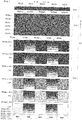
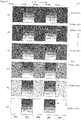
- Fig. 3 is an enlarged view of the testing charts.
- Fig. 4 is an enlarged view of a portion of the testing charts.
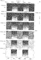
- the testing charts TC are made up of a lowest density head module check pattern TC1, satellite check patterns TC2, and density variable patterns TC3 which include band-by-band density variable patterns TC3a and in-band density variable patterns TC3b.
- the band-by-band density variable patterns TC3a and in-band density variable patterns TC3b of the density variable patterns TC3 are alternately printed in the transverse direction Y. This can facilitate density comparison in the transverse direction Y.
- the lowest density head module check pattern TC1 is a beltlike solid pattern printed by applying the reference voltages set beforehand as drive voltages for all the head modules HM1-HM5, respectively.
- the density at that time is a target density of 60%, for example. Since the density of 60% is not too dense and not too thin, people can visually determine the lowest density head module with ease.
- This lowest density head module check pattern TC1 does not need to be a beltlike solid, but may be a lattice pattern with varying density levels for enabling determination of the lowest density head module by average value.
- Figs. 2 and 3 illustrate the lowest density head module check pattern TC1 as having uniform density in the transverse direction Y, but, in practice, density differences occur among the head modules HM1-HM5. By using this lowest density head module check pattern TC1, the head module with the lowest density when printing with the reference voltage can be determined as the lowest density head module.
- the lowest density head module check pattern TC1 includes a plurality of patches TC11-TC15 juxtaposed in the transverse direction Y.
- imaginary lines are drawn in order to distinguish the patches TC11-TC15, but these imaginary lines are not printed in practice.
- the patches TC11- TC15 correspond to the head modules HM1-HM5, respectively, and are printed by applying, as initial drive voltages to the head modules HM1-HM5, the reference voltages set beforehand for the respective head modules HM1-HM5.
- the satellite check patterns TC2 include beltlike patterns TC2a-TC2f printed with respective drive voltages for all the head modules HM1-HM5 along the transport direction X while changing the drive voltage at predetermined steps from each reference voltage.
- the satellite check patterns TC2 are formed by lowering the drive voltage at steps of -2% from each reference voltage.
- a satellite check pattern TC2a printed with the reference voltage used as drive voltage a satellite check pattern TC2b printed with the reference voltage -2% used as drive voltage
- the satellite check patterns TC2 have density set to 10%, for example, to facilitate distinguishment between main droplet and satellite droplet of the ink droplets.
- a drive voltage that causes the lowest density head module to produce no satellite at the time of printing can be determined to be a satellite-free drive voltage.
- Each of the beltlike satellite check patterns TC2a-TC2f includes a plurality of patches in the transverse direction Y. Each of the patches is distinguishable as to which head module HM has printed, by affixing indexes "1" - "5" to the satellite check patterns TC2a-TC2f.
- patch TC2al is a patch printed by the head module HM1
- patch TC2a2 is a patch printed by the head module HM2.
- the patches TC2a3-TC2a5 are patches printed by the head modules HM3-HM5.
- the band-by-band density variable patterns TC3a of the density variable patterns TC3 are printed with a certain drive voltage over a predetermined length in the transport direction X, and are printed while changing the drive voltages at predetermined steps for each predetermined length in the transport direction X.
- the band-by-band density variable patterns TC3a are in form of plural patches printed with drive voltages varied for each predetermined length as, for example, reference voltage (0%), reference voltage -2%, reference voltage -4%, reference voltage -6%, reference voltage -8%, and reference voltage -10% from downstream in the transport direction X, resulting in patches TC3a (0%), TC3a (-2%), TC3a (-4%), TC3a (-6%), TC3a (-8%), and TC3a (-10%).
- the predetermined length here is 60mm, for example.
- printing is done with the reference voltage for the first 60mm, and with reference voltage -2% for the next 60mm, thus adjusting to lower the reference voltage by steps of -2%, to make variations to reference voltage -10%.
- printing may be started with reference voltage -10%, and gradually raising the drive voltage by steps of +2% up to the reference voltage.
- the in-band density variable patterns TC3b of the density variable patterns TC3 are printed by one of the head modules, e.g. the head module HM2 adjacent the head module HM1, while changing the drive voltage by predetermined steps within the predetermined length in the transport direction X of the band-by-band density variable patterns TC3a of the head module HM1.
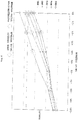
- Figs. 5 and 6 are graphs based on actual measurements.
- Fig. 5 is a graph showing a relationship between satellite-free drive voltage of a head module with the lowest density and satellite-free drive voltages of the other head modules.
- Fig. 6 is a graph showing a relationship between satellite-free drive voltage of a head module with medium density and satellite-free drive voltages of the other head modules.
- density becomes lower as drive voltage is lowered from reference voltage, and each head module has an individual difference in inclination and in satellite-free drive voltage.
- the satellite-free voltage of head module HM1 is -2%
- the satellite-free voltage of head module HM2 is reference voltage 0%
- the satellite-free voltage of head module HM3 is reference voltage -2%
- the satellite-free voltage of head module HM4 is reference voltage -4%
- the satellite-free voltage of head module HM5 is reference voltage -2%.
- a comparison of density between the head modules HM1-HM5 by drive voltage 0% which is reference voltage shows that the lowest density head module is head module HM1, and thus its satellite-free drive voltage is reference voltage -2%.
- a two-dot chain horizontal line is drawn for the density corresponding to the satellite-free drive voltage of this lowest density head module HM1.
- drive voltages in the predetermined steps for the head modules HM2-HM5 other than the lowest density head module HM1 and corresponding to this two-dot chain horizontal line, or drive voltages in the predetermined steps for near positions become the drive voltages for the head modules HM2-HM5, which provide almost the same density as that of the lowest density head module HM1.
- reference voltage -4% becomes the drive voltage for head module HM2
- reference voltage -4% becomes the drive voltage for head module HM3
- reference voltage -6% becomes the drive voltage for head module HM4
- reference voltage -2% is determined as the drive voltage for head module HM5. It will be seen that each drive voltage determined in this way is lower than the satellite-free drive voltage of each of the head modules HM1-HM5. That is, the drive voltages determined in this way provide almost the same density for the respective head modules HM1-HM5, with the ink droplets not including satellite droplets. Thus, the density levels of the five head modules HM1-HM5 can easily be made uniform while inhibiting a deterioration of print quality.
- drive voltages in the predetermined steps for the head modules HM1 and HM3-HM5 other than head module HM2 corresponding to this two-dot chain horizontal line, or drive voltages in the predetermined steps for near positions become the drive voltages for the head modules HM1-HM5, which provide the same density as that of the lowest density head module HM2.
- reference voltage 0% becomes the drive voltage for head module HM1
- reference voltage 0% becomes the drive voltage for head module HM3
- reference voltage -2% becomes the drive voltage for head module HM4
- reference voltage 0% becomes the drive voltage for head module HM5.
- each drive voltage determined in this way is higher than the satellite-free drive voltage to act as reference voltage for each of the head modules HM 1 and HM3-HM5. That is, it will be seen that the drive voltages producing satellite droplets are used as reference voltages, in which almost the same density is assured for the respective head modules HM1-HM5, but which cannot inhibit a deterioration of print quality.
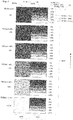
- Fig. 7 is a schematic view showing a procedure of obtaining a new drive voltage for each head module after determining the lowest density head module.
- head module HM1 with the lowest density among them is determined as the lowest density head module (sign P1 in Fig. 7 ).
- a satellite-free drive voltage of the lowest density head module HM1 is determined (sign P2 in Fig. 7 ).
- the satellite-free drive voltage is set as new reference voltage for the lowest density head module HM1 (sign P3 in Fig. 7 ).
- drive voltages of the other head modules HM2-HM5 which are substantially in agreement with the density by the new reference voltage which is the satellite-free voltage for the lowest density head module HM1 are found (sign P4 in Fig.
- This procedure can determine a satellite-free drive voltage for forming ink droplets free of satellite droplets for any one lowest density head among the five head modules HM1-HM5. Then, without repeating the same procedure for the other four head modules to determine satellite-free drive voltages, new drive voltages providing substantially the same density and free of satellite droplets can be determined based on the satellite-free drive voltage of the lowest density head module.
- the oblique broken line which crosses the satellite-free drive voltage (reference voltage -3%) of the head module HM1 in Fig. 7 is set based on Inventors' experience. This graph shows that, in the area below this broken line, satellite droplets do not occur to the ink droplets. Since the drive voltages of the head modules HM2-HM5 corresponding in density level to the satellite-free drive voltage of the lowest density head module HM1 are located in the area below the broken line, it will be appreciated that, by using these drive voltages as new reference voltages, such drive voltages produce no satellite droplets, thereby to inhibit a deterioration of print quality.
- Fig. 8 is a flow chart showing the sequence of the head voltage correction process.
- Figs. 9 through 12 are schematic views showing specific examples of obtaining a new drive voltage for each head module.
- a step value and the number of steps for shifting voltage relative to reference voltage are stored in the storage unit 23.
- the step value is -2% and the number of steps is six, for example.
- the step value which is a rate by which this drive voltage is changed may be -1% or -3%, and this may be set according to the characteristics of the head modules HM1-HM5 or drivers 25.
- Each reference voltage acquired at the time of adjustment of individual head modules HM1-HM5 is also stored beforehand in the storage unit 23.
- the controller 21, by referring to the storage unit 23, sets a reference voltage for each of the head modules HM1-HM5.
- the step value and the number of steps for shifting drive voltage have been set beforehand to the controller 21.
- the step value and the number of steps may be set to the controller 21 by the operator inputting them from the input unit 32 to the controller 21, or by referring to the storage unit 23.
- Step S2 (corresponding to the "testing chart printing step” in this invention)
- the controller 21 causes the testing charts TC as shown in Figs. 2 - 4 to be printed on the web paper WP.
- Step S3 (corresponding to the "image acquiring step” in this invention)
- the controller 21 operates various components to cause the scanning unit 17 to read the testing chart TC. Consequently, the testing charts TC are acquired as digitized testing chart images.
- Step S4 (corresponding to the "lowest density head module determining step” in this invention)
- the image processor 27 performs a density comparison of the lowest density head module check pattern TC1 of the testing charts TC. Specifically, for example, density values of the plurality of patches TC1-TC15 of the lowest density head module check pattern TC1 are obtained for the respective head modules HM1-HM5.
- the determiner 29 identifies one with the lowest density from the density values of the plurality of patches TC11-TC15 obtained by the image processor 27, and determines the head module which can print the lowest density head module check pattern TC1 with the lowest density among the five head modules HM1-HM5.
- the head module determined in this way is regarded as the lowest density head module.
- patch TC13 has the lowest density, and therefore the head module HM3 is regarded as the lowest density head module.
- a position corresponding to the lowest density head module HM3 is shown in a white dotted line in the lowest density head module check pattern TC1 in Fig. 9 .
- the operator may measure the density levels of the patches TC11-TC15 formed in the testing charts TC, and may identify a patch with the lowest density based on the measured density levels from among the plurality of patches TC1-TC15.
- Step S5 (corresponding to the "satellite-free drive voltage determining step” and “reference pattern determining step” in this invention)
- the image processor 27 finds a distance between main droplet and satellite droplet of ink droplets for each drive voltage with respect to the plurality of patches printed by the lowest density head module HM3 among the satellite check patterns TC2 of the testing charts TC. Specifically, the image processor 27 analyzes the scanned image of each of the patches (TC2a3, TC2b3, TC2c3, TC2d3, TC2e3, and TC2f3) of the satellite check patterns TC2 printed by applying a plurality of drive voltages of different strengths to the head module HM3 which is the lowest density head module, and calculates a distance between main droplet and satellite droplet on each patch.
- the determiner 29 determines a patch, including no satellite droplet, of the satellite check patterns TC2 based on the distance between main droplet and satellite droplet calculated by the image processor 27 (determination of a reference pattern). Then, the drive voltage applied to the lowest density head module HM3 when that patch was printed is determined to be a satellite-free drive voltage. It is assumed here that a satellite droplet or droplets is/are included in patch TC2a3, but no satellite droplet is included in patch TC2b3 shown in a white line in the satellite check patterns TC2 of Fig. 9 , nor in patches TC2c3-TC2f3.
- the determiner 29 determines the drive voltage applied to the head module HM3 at the time of printing the patch TC2b3 to be a satellite-free drive voltage.
- This satellite-free drive voltage becomes a new drive voltage for the lowest density head module HM3. That is, for the lowest density head module HM3, reference voltage -2% becomes a new reference voltage.
- the position of the patch (TC2b3) corresponding to the satellite-free drive voltage is shown in a white dotted line in the satellite check patterns TC2 in Fig. 9 .
- the operator may be made to read the patches (TC2a3, TC2b3, TC2c3, TC2d3, TC2e3, and TC2f3) of the satellite check patterns TC2, and to determine a patch free from satellite droplets, from among these patches.
- the operator inputs from the input unit 32 to the controller 21 the drive voltage at the time of printing the patch free from satellite droplets as new reference voltage for the lowest density head module HM3.
- Step S6 (corresponding to the "new reference voltage determining step” in this invention)
- the image processor 27, regarding the density variable patterns TC3 of the testing charts TC first determines all differences in density value in the transverse direction Y between the patches of band-by-band density variable patterns TC3a and the patches of in-band density variable patterns TC3b.
- the determiner 29 determines, regarding band-by-band density variable pattern TC3a (patch TC3a (-2%) shown in a white dotted line in Fig.
- the determiner 29 determines reference voltage -4% of head module HM2 to be a new reference voltage for head module HM2. Similarly, the determiner 29 determines reference voltage -2% of head module HM4 as a new reference voltage for head module HM4.
- the operator may be made to measure the density of each of the patches of density variable patterns TC3, e.g. TC3a (-2%), TC3b (0%), TC3b (-2%), TC3b (-4%), TC3b (-6%), TC3b (-8%), and TC3b (-10%), and to determine patches of the same density as patch T3a (-2%) from the density variable patterns TC3b.
- the operator inputs, from the input unit 32 to the controller 21, the drive voltages at the time of printing the patches determined in this way as new drive voltages for the head modules HM2 and HM4.
- the determiner 29, as shown in Fig. 11 searches patches (TC3b (-4%)) of in-band density variable patterns TC3b printed by the new reference voltage (reference voltage -4%) applied to the head module HM2, and patches TC3a (0%), TC3a (-2%), TC3a (-4%), TC3a (-6%), TC3a (-8%), and TC3a (-10%) of band-by-band density variable patterns TC3a of the further adjacent head module HM1, for a patch having density in agreement in a direction perpendicular to the transverse direction Y.
- the determiner 29 determines the drive voltage applied to the head module HM1 when printing the patch, having density in agreement, of band-to-band density variable patterns TC3a to be a new voltage for the head module HM1. It is assumed here that, as a result of density comparison shown in white arrows and black arrows in Fig. 11 , patch TC3b (-4%) by the head module HM2 and patch TCa3a (-2%) by the head module HM1 have density in agreement as shown in white dotted lines. Consequently, the determiner 29 determines reference voltage -2% of the head module HM1 to be a new reference voltage for the head module HM1.
- the determiner 29 searches patches (TC3b (-2%)) of in-band density variable patterns TC3b printed by the new reference voltage (reference voltage -2%) applied to the head module HM4, and patches TC3a (0%), TC3a (-2%), TC3a (-4%), TC3a (-6%), TC3a (-8%), and TC3a (-10%) of band-by-band density variable patterns TC3a of the further adjacent head module HM5, for a patch having density in agreement in the transverse direction Y.
- the determiner 29 determines the drive voltage applied to the head module HM5 when printing the patch, having density in agreement, of band-to-band density variable patterns TC3a to be a new voltage for the head module HM5. It is assumed here that, as a result of density comparison shown in white arrows and black arrows in Fig. 12 , patch TC3b (-2%) by the head module HM4 and patch TCa3a (-2%) by the head module HM5 have density in agreement as shown in white dotted lines. Consequently, the determiner 29 determines reference voltage -2% of the head module HM1 to be a new reference voltage for the head module HM5.
- the new reference voltage for each of the head modules HM1-HM5 determined in this way by the determiner 29 is stored in the storage unit 23 through the controller 21. At this time, the original reference voltages of the head modules HM1-HM5 stored beforehand are rewritten to be updated.
- the lowest density head module is HM3 and the density variable patterns TC3 are band-to-band density variable patterns TC3a.
- the lowest density head module is the head module HM4 which corresponds to the in-band density variable patterns TC3b of the density variable patterns TC3
- the above new reference voltage may be determined as shown in Fig. 13 .
- supposing the satellite-free drive voltage of the lowest density head module HM4 is reference voltage -2%
- drive voltages may be determined, by the above technique, which provide density in agreement between the further head modules.
- one lowest density head module HM3 is determined out of five head modules HM1-HM5 by using the lowest density head module check pattern TC1, a satellite-free drive voltage is determined based on this lowest density head module HM3 and satellite check patterns TC2, and this drive voltage is set as a new reference voltage for the lowest density head module HM3, Then, drive voltages corresponding to in-band density variable patterns TC3b of adjacent head modules HM2 and HM4 having density in agreement with the density by the satellite-free drive voltage of band-by-band density variable patterns TC3a printed by the lowest density head module HM3 are set as new reference voltages for the adjacent head modules HM2 and HM4.
- the adjacent head modules HM2 and HM4 and further adjacent head modules HM1 and HM5 which are lower than that of the lowest density head module HM3 become reference voltages, the adjacent head modules HM2 and HM4 and further adjacent head modules HM1 and HM5 are also given drive voltages free of satellites.
- the density levels of ink droplets can easily be uniformed among the five head modules HM1-HM5, while inhibiting a deterioration of print quality.
Landscapes
- Engineering & Computer Science (AREA)
- Quality & Reliability (AREA)
- General Engineering & Computer Science (AREA)
- Physics & Mathematics (AREA)
- General Physics & Mathematics (AREA)
- Theoretical Computer Science (AREA)
- Ink Jet (AREA)
Claims (7)
- Tintenstrahldruckvorrichtung (3) zum Drucken auf einem Druckmedium (WP) durch Abgabe von Tintentröpfchen darauf, wobei die Vorrichtung umfasst:einen Kopf (19) mit einer Vielzahl von Kopfmodulen (HM1-HM5), die in einer Richtung senkrecht zu einer Transportrichtung des Druckmediums (WP) angeordnet sind, wobei jedes der Kopfmodule (HM1-HM5) eine Vielzahl von Düsen zur Abgabe der Tintentröpfchen aufweist;eine Transporteinrichtung (7, 11), die in einer Position beabstandet von und gegenüber dem Kopf (19) zum Transportieren des Druckmediums (WP) angeordnet ist; undeinen Druckcontroller zum Drucken von Testmustern (TC) auf das Druckmedium (WP), wobei die Testmuster (TC) umfassenein Prüfmuster für das Kopfmodul mit niedrigster Dichte (TC1), das unter Verwendung einer zuvor für jedes der Kopfmodule festgelegten Referenzspannung als Antriebsspannung gedruckt wird;Satellitenprüfmuster (TC2), die mit entsprechenden Antriebsspannungen entlang der Transportrichtung gedruckt werden, wobei die Antriebsspannung in vorgegebenen Schritten von der Referenzspannung für jedes der Kopfmodule geändert wird;dadurch gekennzeichnet, dass die Testmuster ferner umfassenBand-zu-Band-dichtevariable Muster (TC3a), die von einem der Kopfmodule gedruckt werden, unter Verwendung einer bestimmten Antriebsspannung über eine vorbestimmte Länge in der Transportrichtung, während die Antriebsspannung in einem vorbestimmten Schritt für jede vorbestimmte Länge in der Transportrichtung geändert wird; undIn-Band-dichtevariable Muster (TC3b), die von einem Kopfmodul neben dem einen der Kopfmodule gedruckt werden, während die Antriebsspannung in einem vorbestimmten Schritt innerhalb der vorbestimmten Länge in der Transportrichtung der Band-zu-Banddichtevariablen-Muster geändert wird;wobei aus dem Prüfmuster für das Kopfmodul mit niedrigster Dichte (TC1) ein Kopfmodul mit minimaler Dichte als Kopfmodul mit niedrigster Dichte bestimmt wird;wobei aus den Satellitenprüfmustern (TC2) die Antriebsspannung, die nicht dazu führt, dass das Kopfmodul mit der niedrigsten Dichte Satelliten erzeugt, als satellitenfreie Antriebsspannung bestimmt wird, und die satellitenfreie Antriebsspannung als neue Referenzspannung für das Kopfmodul mit der niedrigsten Dichte bestimmt wird; undwobei in Bezug auf die Band-zu-Band dichtevariablen Muster (TC3a), die unter Verwendung der satellitenfreien Ansteuerspannung unter den Band-zu-Band dichtevariable Mustern (TC3a) durch das Kopfmodul mit der niedrigsten Dichte und die In-Band dichtevariablen Muster (TC3b) durch das benachbarte Kopfmodul gedruckt werden, eine Ansteuerspannung der In-Band dichtevariablen Muster (TC3b) des benachbarten Kopfmoduls mit einer Dichte in Übereinstimmung mit der Richtung senkrecht zur Transportrichtung als eine neue Referenzspannung für das benachbarte Kopfmodul bestimmt wird, oder bezüglich derjenigen, die unter Verwendung der satellitenfreien Steuerspannung der In-Band dichtevariablen Muster (TC3b) durch das Kopfmodul mit der niedrigsten Dichte und der Band-zu-Band dichtevariablen Muster (TC3a) durch das benachbarte Kopfmodul gedruckt werden, eine Antriebsspannung der Band-zu-Band dichtevariablen Muster (TC3a) des benachbarten Kopfmoduls mit einer Dichte in Übereinstimmung mit der Richtung senkrecht zur Transportrichtung als eine neue Referenzspannung für das benachbarte Kopfmodul bestimmt wird,wobei wenn ein weiteres angrenzendes Kopfmodul neben dem angrenzenden Kopfmodul vorgesehen ist,in Bezug auf diejenigen, die unter Verwendung der neuen Referenzspannung für das benachbarte Kopfmodul von den In-Band dichtevariablen Mustern (TC3b) durch das benachbarte Kopfmodul und den Band-zu-Band dichtevariablen Mustern (TC3a) durch das weitere benachbarte Kopfmodul unter den Band-zu-Band dichtevariablen Mustern (TC3a) durch das weitere benachbarte Kopfmodul neben dem benachbarten Kopfmodul gedruckt werden, eine Antriebsspannung der Band-zu-Band dichtevariablen Muster (TC3a) des weiteren benachbarten Kopfmoduls mit einer Dichte in Übereinstimmung mit der Richtung senkrecht zur Transportrichtung als neue Referenzspannung für das weitere benachbarte Kopfmodul bestimmt wird,oder in Bezug auf diejenigen, die unter Verwendung der neuen Referenzspannung für das benachbarte Kopfmodul von den Band-zu-Band dichtevariablen Mustern (TC3a) durch das benachbarte Kopfmodul und der In-Band dichtevariablen Muster (Tc3b) durch das weitere benachbarte Kopfmodul unter den In-Band dichtevariablen Mustern (Tc3b) durch das weitere benachbarte Kopfmodul neben dem benachbarten Kopfmodul gedruckt werden, eine Antriebsspannung der In-Band dichtevariablen Muster (TC3b) des weiter benachbarten Kopfmoduls mit einer Dichte in Übereinstimmung mit der Richtung senkrecht zur Transportrichtung als neue Referenzspannung für das weiter benachbarte Kopfmodul bestimmt wird.
- Tintenstrahldruckvorrichtung (3) gemäß Anspruch 1, weiter aufweisend:eine Bilderfassungseinheit (17) zum Erfassen von Testmusterbildern durch Scannen der auf das Druckmedium (WP) gedruckten Testmuster; undeinen Referenzspannungsbestimmer (27, 29) zum Bestimmen des Kopfmoduls mit der niedrigsten Dichte, der satellitenfreien Antriebsspannung und der neuen Referenzspannung, indem eine Bildverarbeitung der Testmusterbilder durchgeführt wird.
- Ein Kopfspannungskorrekturprogramm für eine Tintenstrahldruckvorrichtung (3), die ein Drucken auf einem Druckmedium (WP) mit einem Kopf (19) durchführt, der eine Vielzahl von Kopfmodulen (HM1-HM5) aufweist, von denen jedes eine Vielzahl von Düsen zum Ausgeben von Tintentröpfchen aufweist, wobei die Kopfmodule (HM1-HM5) in einer Richtung senkrecht zu einer Transportrichtung des Druckmediums (WP) angeordnet sind, wobei das Programm die folgenden Prozesse umfasst, die durch einen Controller ausgeführt werden:einen Testmusterdruckprozess zum Drucken von Testmustern auf das Druckmedium (WP), wobei die Testmuster umfassen:ein Prüfmuster für das Kopfmodul mit niedrigster Dichte (TC1), das unter Verwendung einer zuvor für jedes der Kopfmodule festgelegten Referenzspannung als Steuerspannung gedruckt wird;Satellitenprüfmuster (TC2), die mit entsprechenden Antriebsspannungen entlang der Transportrichtung gedruckt werden, wobei die Antriebsspannung in vorgegebenen Schritten von der Referenzspannung für jedes der Kopfmodule geändert wird;dadurch gekennzeichnet, dass die Testmuster ferner umfassenBand-zu-Band dichtevariable Muster (TC3a), die von einem der Kopfmodule gedruckt werden, jedes unter Verwendung einer bestimmten Antriebsspannung über eine vorbestimmte Länge in Transportrichtung, wobei die Muster, während die Antriebsspannung in vorbestimmten Schritten für jede vorbestimmte Länge in Transportrichtung geändert wird, gedruckt werden; undIn-Band dichtevariable Muster (TC3b), die von einem Kopfmodul neben dem einen der Kopfmodule gedruckt werden, wobei jedes der Muster durch Ändern der Antriebsspannung in vorbestimmten Schritten innerhalb der vorbestimmten Länge in der Transportrichtung der Band-zu-Band dichtevariablen Muster (TC3a) geändert wird;einen Prozess zur Bestimmung eines Kopfmoduls niedrigster Dichte, um aus dem Prüfmuster des Kopfmoduls mit niedrigster Dichte (TC1) ein Kopfmodul mit minimaler Dichte als Kopfmodul niedrigster Dichte zu bestimmen;einen satellitenfreien Antriebsspannungsbestimmungsprozess zur Bestimmung, aus den Satellitenprüfmustern (TC2), der Antriebsspannung, die nicht dazu führt, dass das Kopfmodul mit der niedrigsten Dichte Satelliten erzeugt, als satellitenfreie Antriebsspannung, und zur Bestimmung der satellitenfreien Antriebsspannung als neue Referenzspannung für das Kopfmodul mit der niedrigsten Dichte; undeinen neuen Bezugsspannung-Bestimmungsprozess zur Bestimmung, in Bezug auf die Band-zu-Band dichtevariablen Muster (TC3a), die unter Verwendung der satellitenfreien Ansteuerspannung unter den Band-zu-Band dichtevariablen Mustern (TC3a) durch das Kopfmodul mit der niedrigsten Dichte und den In-Band dichtevariablen Mustern (TC3b) durch das benachbarte Kopfmodul gedruckt werden, einer Antriebsspannung der In-Band dichtevariablen Muster (TC3b) des benachbarten Kopfmoduls mit einer Dichte in Übereinstimmung mit der Richtung senkrecht zur Transportrichtung als eine neue Referenzspannung für das benachbarte Kopfmodul, oder zur Bestimmung, bezüglich derjenigen, die unter Verwendung der satellitenfreien Antriebsspannung der In-Band dichtevariablen Muster (TC3b) durch das Kopfmodul mit der niedrigsten Dichte und der Band-zu-Band dichtevariablen Muster (TC3a) durch das benachbarte Kopfmodul gedruckt werden, einer Antriebsspannung der Band-zu-Band dichtevariablen Muster (TC3a) des benachbarten Kopfmoduls mit einer Dichte in Übereinstimmung mit der Richtung senkrecht zur Transportrichtung als eine neue Referenzspannung für das benachbarte Kopfmodul,wobei wenn ein weiteres angrenzendes Kopfmodul neben dem angrenzenden Kopfmodul vorgesehen ist,zur Bestimmung, in Bezug auf diejenigen, die unter Verwendung der neuen Referenzspannung für das benachbarte Kopfmodul von den In-Band dichtevariablen Mustern (TC3b) durch das benachbarte Kopfmodul und den Band-zu-Band dichtevariablen Mustern (TC3a) durch das weitere benachbarte Kopfmodul unter den Band-zu-Band dichtevariablen Mustern (TC3a) durch das weitere benachbarte Kopfmodul neben dem benachbarten Kopfmodul gedruckt werden, einer Antriebsspannung der Band-zu-Band dichtevariablen Muster (TC3a) des weiter benachbarten Kopfmoduls mit einer Dichte in Übereinstimmung mit der Richtung senkrecht zur Transportrichtung als neue Referenzspannung für das weitere benachbarte Kopfmodul, oder zur Bestimmung, in Bezug auf diejenigen, die unter Verwendung der neuen Referenzspannung für das benachbarte Kopfmodul von den Band-zu-Band dichtevariablen Mustern (TC3a) durch das benachbarte Kopfmodul und der In-Band dichtevariablen Muster (TC3b) durch das weitere benachbarte Kopfmodul unter den In-Band dichtevariablen Mustern (TC3b) durch das weitere benachbarte Kopfmodul neben dem benachbarten Kopfmodul gedruckt werden, einer Antriebsspannung der In-Band dichtevariablen Muster (TC3b) des weiteren benachbarten Kopfmoduls mit einer Dichte in Übereinstimmung mit der Richtung senkrecht zur Transportrichtung als neue Referenzspannung für das weitere benachbarte Kopfmodul.
- Ein Kopfspannungskorrekturverfahren für eine Tintenstrahldruckvorrichtung (3), die ein Drucken mit einem Kopf (19) mit einem ersten und einem zweiten Kopfmodul, die jeweils eine Vielzahl von Düsen zum Ausgeben von Tintentröpfchen aufweisen, auf einem Druckmedium (WP), das sich relativ zu dem Kopf (19) bewegt, durchführt, wobei das Verfahren umfasst:einen Schritt zum Bestimmen eines Kopfmoduls niedrigster Dichte, um zu bewirken, dass das erste und das zweite Kopfmodul Prüfmuster für das Kopfmodul mit niedrigster Dichte (TC1) auf das Druckmedium (WP) drucken, indem eine Referenzspannung an jedes des ersten und des zweiten Kopfmoduls angelegt wird, und zum Bestimmen eines Kopfmoduls niedrigster Dichte, das in der Lage ist, auf das Druckmedium (WP) in geringerer Dichte zu drucken, zwischen dem ersten und dem zweiten Kopfmodul, indem eines der Prüfmuster für das Kopfmodul mit niedrigster Dichte (TC1) mit der geringeren Dichte zwischen den Prüfmustern für das Kopfmodul mit niedrigster Dichte bestimmt wird;einen satellitenfreien Antriebsspannung-Bestimmungsschritt zum Bewirken, dass das Kopfmodul mit der niedrigsten Dichte eine Vielzahl von Satellitenprüfmustern (TC2) auf das Druckmedium (WP) druckt, indem daran eine Vielzahl von unterschiedlich starken Antriebsspannungen angelegt wird, die niedriger als die Referenzspannung sind, zum Identifizieren eines satellitenfreien Musters aus der Vielzahl von Satellitenprüfmustern (TC2) und zum Bestimmen der Antriebsspannung zu der Zeit des satellitenfreien Musters als eine satellitenfreie Antriebsspannung;einen Referenzmuster-Bestimmungsschritt zur Bestimmung des satellitenfreien Musters als Referenzmuster; undeinen neuen Bezugsspannung-Bestimmungsschritt, um ein Kopfmodul mit nicht niedrigster Dichte, das nicht dem Kopfmodul mit der niedrigsten Dichte aus den ersten und zweiten Kopfmodulen entspricht, dazu zu veranlassen, eine Vielzahl von dichtevariablen Mustern (TC3) auf das Druckmedium (WP) zu drucken, indem daran eine Vielzahl von unterschiedlich starken Antriebsspannungen angelegt wird, die niedriger sind als die satellitenfreie Antriebsspannung, zum Identifizieren eines Musters mit der gleichen Dichte wie das Referenzmuster aus den dichtevariablen Mustern (TC3), zum Einstellen der Antriebsspannung der Zeit des Dichtemusters als neue Referenzspannung für das Kopfmodul mit der nicht geringsten Dichte und zum Einstellen der satellitenfreien Antriebsspannung als neue Referenzspannung für das Kopfmodul mit der geringsten Dichte.
- Kopfspannungskorrekturverfahren für eine Tintenstrahldruckvorrichtung (3) nach Anspruch 4, wobei ein Bediener veranlasst wird, die Dichte der Prüfmuster (TC1) des Kopfmoduls mit der niedrigsten Dichte zu messen, und der Bediener veranlasst wird, ein Prüfmuster des Kopfmoduls mit der niedrigsten Dichte (TC1) unter den Prüfmustern mit niedrigster Dichte (TC1) zu bestimmen.
- Kopfspannungskorrekturverfahren für eine Tintenstrahldruckvorrichtung (3) nach Anspruch 4, bei dem ein Bediener dazu gebracht wird, die Satellitenprüfmuster (TC2) zu lesen, und der Bediener dazu gebracht wird, ein satellitenfreies Muster aus den Satellitenprüfmustern (TC2) zu bestimmen.
- Kopfspannungskorrekturverfahren für ein Tintenstrahldruckgerät (4) nach Anspruch 4, wobei ein Bediener veranlasst wird, die Dichte der dichtevariablen Muster (TC3) zu messen, und der Bediener veranlasst wird, ein Muster mit der gleichen Dichte wie das Referenzmuster aus den dichtevariablen Mustern (TC3) zu bestimmen.
Applications Claiming Priority (1)
| Application Number | Priority Date | Filing Date | Title |
|---|---|---|---|
| JP2017234408A JP6979867B2 (ja) | 2017-12-06 | 2017-12-06 | インクジェット印刷装置のヘッド電圧補正方法及びそれを用いた装置並びにそのプログラム |
Publications (2)
| Publication Number | Publication Date |
|---|---|
| EP3495150A1 EP3495150A1 (de) | 2019-06-12 |
| EP3495150B1 true EP3495150B1 (de) | 2020-09-23 |
Family
ID=64606813
Family Applications (1)
| Application Number | Title | Priority Date | Filing Date |
|---|---|---|---|
| EP18210335.8A Active EP3495150B1 (de) | 2017-12-06 | 2018-12-05 | Kopfspannungskorrekturverfahren für tintenstrahlvorrichtung, vorrichtung mit verwendung davon und programm dafür |
Country Status (3)
| Country | Link |
|---|---|
| US (1) | US10668759B2 (de) |
| EP (1) | EP3495150B1 (de) |
| JP (1) | JP6979867B2 (de) |
Family Cites Families (12)
| Publication number | Priority date | Publication date | Assignee | Title |
|---|---|---|---|---|
| JP4497825B2 (ja) | 2003-03-10 | 2010-07-07 | キヤノン株式会社 | インクジェット記録方法及びインクジェット記録装置 |
| US6767082B1 (en) * | 2003-06-09 | 2004-07-27 | Xerox Corporation | Systems and methods for varying fluid path geometry for fluid ejection system |
| JP4356553B2 (ja) * | 2004-08-19 | 2009-11-04 | 富士ゼロックス株式会社 | インクジェット記録装置及びインクジェット記録装置の調整方法 |
| CN101391524B (zh) * | 2007-09-17 | 2012-01-18 | 财团法人工业技术研究院 | 喷墨装置以及校正方法 |
| JP5447160B2 (ja) * | 2010-05-07 | 2014-03-19 | セイコーエプソン株式会社 | 流体噴射装置の調整方法及び流体噴射装置の製造方法 |
| US8511776B2 (en) * | 2010-07-12 | 2013-08-20 | Hewlett-Packard Development Company, L.P. | Maintaining optical density of images produced by a printing device |
| JP2013244712A (ja) * | 2012-05-29 | 2013-12-09 | Riso Kagaku Corp | インクジェット印刷装置 |
| JP6178708B2 (ja) * | 2013-11-26 | 2017-08-09 | 理想科学工業株式会社 | インクジェット画像形成装置 |
| JP2016002662A (ja) | 2014-06-13 | 2016-01-12 | 株式会社リコー | 記録装置及び補正方法 |
| JP2016124245A (ja) * | 2015-01-07 | 2016-07-11 | セイコーエプソン株式会社 | 液体吐出装置及び液体吐出装置の吐出速度調整方法 |
| JP6591249B2 (ja) * | 2015-09-29 | 2019-10-16 | 株式会社Screenホールディングス | 検査用チャート及びインクジェット印刷装置の補正値取得方法並びにインクジェット印刷装置 |
| JP6919211B2 (ja) * | 2017-02-03 | 2021-08-18 | セイコーエプソン株式会社 | 印刷装置および印刷装置における入力電圧の較正方法 |
-
2017
- 2017-12-06 JP JP2017234408A patent/JP6979867B2/ja active Active
-
2018
- 2018-12-05 EP EP18210335.8A patent/EP3495150B1/de active Active
- 2018-12-05 US US16/210,854 patent/US10668759B2/en active Active
Non-Patent Citations (1)
| Title |
|---|
| None * |
Also Published As
| Publication number | Publication date |
|---|---|
| JP2019098676A (ja) | 2019-06-24 |
| JP6979867B2 (ja) | 2021-12-15 |
| EP3495150A1 (de) | 2019-06-12 |
| US20190168513A1 (en) | 2019-06-06 |
| US10668759B2 (en) | 2020-06-02 |
Similar Documents
| Publication | Publication Date | Title |
|---|---|---|
| US8292393B2 (en) | Recording apparatus and transport method | |
| CN113924212B (zh) | 喷墨印刷中的故障喷嘴补偿和非均匀性校正的方法和系统 | |
| US10800193B2 (en) | Nozzle operating situation checking method for inkjet printing apparatus, an inkjet printing apparatus, and a program thereof | |
| US7914100B2 (en) | Recording apparatus and transport amount correcting method | |
| US8985733B2 (en) | Pattern inspection apparatus, pattern inspection method, and printer | |
| CN114598780A (zh) | 图像检查装置以及位置偏移测定方法 | |
| US10576736B2 (en) | Head voltage correcting method for inkjet printing apparatus, and an apparatus using same | |
| US9757967B2 (en) | Testing chart, a correction value acquiring method for an inkjet printing apparatus, and an inkjet printing apparatus | |
| EP3654628A1 (de) | Bilderzeugungsvorrichtung, schattierungskorrekturverfahren für bilderzeugungsvorrichtung und schattierungskorrekturprogramm | |
| EP3495150B1 (de) | Kopfspannungskorrekturverfahren für tintenstrahlvorrichtung, vorrichtung mit verwendung davon und programm dafür | |
| US9283752B2 (en) | Method for printing contiguous swaths | |
| JP2011073186A (ja) | 印刷装置の製造方法、及び、印刷装置 | |
| US11167547B2 (en) | Printing apparatus, and a deviation amount calculating method therefor | |
| JP2020037209A (ja) | インクジェット記録装置、インクジェット記録方法、およびプログラム | |
| EP4311679A1 (de) | Steuergerät, bilderzeugungssystem, verfahren zur erkennung von entladungsdefektdüsen und medium | |
| EP3705299A1 (de) | Tintenstrahlaufzeichnungsvorrichtung und verfahren zur einstellung der ergänzung einer defekten düse | |
| US7770996B2 (en) | Transporting method and recording apparatus | |
| EP3957484A1 (de) | Verminderung der streifigkeit beim tintenstrahldruck | |
| US20250196509A1 (en) | Printing apparatus and control method | |
| US20250242601A1 (en) | Landing position deviation amount detection method, printing apparatus, and non-transitory computer-readable recording medium recording landing position deviation amount detection program | |
| US20240075735A1 (en) | Inkjet printer, image formation method, and computer readable recording medium storing image formation program | |
| US20250121609A1 (en) | Compensation coefficient determination method and printing method | |
| EP4321344B1 (de) | Steuergerät, bilderzeugungssystem, verfahren zur erkennung von entladungsdefektdüsen und medium | |
| US20240198659A1 (en) | Printing apparatus, method for controlling printing apparatus, and storage medium | |
| US10189272B2 (en) | Correction value acquiring method for inkjet printing apparatus, and an inkjet printing apparatus |
Legal Events
| Date | Code | Title | Description |
|---|---|---|---|
| PUAI | Public reference made under article 153(3) epc to a published international application that has entered the european phase |
Free format text: ORIGINAL CODE: 0009012 |
|
| STAA | Information on the status of an ep patent application or granted ep patent |
Free format text: STATUS: THE APPLICATION HAS BEEN PUBLISHED |
|
| AK | Designated contracting states |
Kind code of ref document: A1 Designated state(s): AL AT BE BG CH CY CZ DE DK EE ES FI FR GB GR HR HU IE IS IT LI LT LU LV MC MK MT NL NO PL PT RO RS SE SI SK SM TR |
|
| AX | Request for extension of the european patent |
Extension state: BA ME |
|
| STAA | Information on the status of an ep patent application or granted ep patent |
Free format text: STATUS: REQUEST FOR EXAMINATION WAS MADE |
|
| 17P | Request for examination filed |
Effective date: 20191212 |
|
| RBV | Designated contracting states (corrected) |
Designated state(s): AL AT BE BG CH CY CZ DE DK EE ES FI FR GB GR HR HU IE IS IT LI LT LU LV MC MK MT NL NO PL PT RO RS SE SI SK SM TR |
|
| GRAP | Despatch of communication of intention to grant a patent |
Free format text: ORIGINAL CODE: EPIDOSNIGR1 |
|
| STAA | Information on the status of an ep patent application or granted ep patent |
Free format text: STATUS: GRANT OF PATENT IS INTENDED |
|
| INTG | Intention to grant announced |
Effective date: 20200414 |
|
| GRAS | Grant fee paid |
Free format text: ORIGINAL CODE: EPIDOSNIGR3 |
|
| GRAA | (expected) grant |
Free format text: ORIGINAL CODE: 0009210 |
|
| STAA | Information on the status of an ep patent application or granted ep patent |
Free format text: STATUS: THE PATENT HAS BEEN GRANTED |
|
| AK | Designated contracting states |
Kind code of ref document: B1 Designated state(s): AL AT BE BG CH CY CZ DE DK EE ES FI FR GB GR HR HU IE IS IT LI LT LU LV MC MK MT NL NO PL PT RO RS SE SI SK SM TR |
|
| REG | Reference to a national code |
Ref country code: GB Ref legal event code: FG4D |
|
| REG | Reference to a national code |
Ref country code: CH Ref legal event code: EP |
|
| REG | Reference to a national code |
Ref country code: IE Ref legal event code: FG4D |
|
| REG | Reference to a national code |
Ref country code: AT Ref legal event code: REF Ref document number: 1316003 Country of ref document: AT Kind code of ref document: T Effective date: 20201015 Ref country code: DE Ref legal event code: R096 Ref document number: 602018008093 Country of ref document: DE |
|
| PG25 | Lapsed in a contracting state [announced via postgrant information from national office to epo] |
Ref country code: FI Free format text: LAPSE BECAUSE OF FAILURE TO SUBMIT A TRANSLATION OF THE DESCRIPTION OR TO PAY THE FEE WITHIN THE PRESCRIBED TIME-LIMIT Effective date: 20200923 Ref country code: GR Free format text: LAPSE BECAUSE OF FAILURE TO SUBMIT A TRANSLATION OF THE DESCRIPTION OR TO PAY THE FEE WITHIN THE PRESCRIBED TIME-LIMIT Effective date: 20201224 Ref country code: SE Free format text: LAPSE BECAUSE OF FAILURE TO SUBMIT A TRANSLATION OF THE DESCRIPTION OR TO PAY THE FEE WITHIN THE PRESCRIBED TIME-LIMIT Effective date: 20200923 Ref country code: HR Free format text: LAPSE BECAUSE OF FAILURE TO SUBMIT A TRANSLATION OF THE DESCRIPTION OR TO PAY THE FEE WITHIN THE PRESCRIBED TIME-LIMIT Effective date: 20200923 Ref country code: BG Free format text: LAPSE BECAUSE OF FAILURE TO SUBMIT A TRANSLATION OF THE DESCRIPTION OR TO PAY THE FEE WITHIN THE PRESCRIBED TIME-LIMIT Effective date: 20201223 Ref country code: NO Free format text: LAPSE BECAUSE OF FAILURE TO SUBMIT A TRANSLATION OF THE DESCRIPTION OR TO PAY THE FEE WITHIN THE PRESCRIBED TIME-LIMIT Effective date: 20201223 |
|
| REG | Reference to a national code |
Ref country code: AT Ref legal event code: MK05 Ref document number: 1316003 Country of ref document: AT Kind code of ref document: T Effective date: 20200923 |
|
| PG25 | Lapsed in a contracting state [announced via postgrant information from national office to epo] |
Ref country code: LV Free format text: LAPSE BECAUSE OF FAILURE TO SUBMIT A TRANSLATION OF THE DESCRIPTION OR TO PAY THE FEE WITHIN THE PRESCRIBED TIME-LIMIT Effective date: 20200923 Ref country code: RS Free format text: LAPSE BECAUSE OF FAILURE TO SUBMIT A TRANSLATION OF THE DESCRIPTION OR TO PAY THE FEE WITHIN THE PRESCRIBED TIME-LIMIT Effective date: 20200923 |
|
| REG | Reference to a national code |
Ref country code: NL Ref legal event code: MP Effective date: 20200923 |
|
| REG | Reference to a national code |
Ref country code: LT Ref legal event code: MG4D |
|
| PG25 | Lapsed in a contracting state [announced via postgrant information from national office to epo] |
Ref country code: EE Free format text: LAPSE BECAUSE OF FAILURE TO SUBMIT A TRANSLATION OF THE DESCRIPTION OR TO PAY THE FEE WITHIN THE PRESCRIBED TIME-LIMIT Effective date: 20200923 Ref country code: RO Free format text: LAPSE BECAUSE OF FAILURE TO SUBMIT A TRANSLATION OF THE DESCRIPTION OR TO PAY THE FEE WITHIN THE PRESCRIBED TIME-LIMIT Effective date: 20200923 Ref country code: PT Free format text: LAPSE BECAUSE OF FAILURE TO SUBMIT A TRANSLATION OF THE DESCRIPTION OR TO PAY THE FEE WITHIN THE PRESCRIBED TIME-LIMIT Effective date: 20210125 Ref country code: CZ Free format text: LAPSE BECAUSE OF FAILURE TO SUBMIT A TRANSLATION OF THE DESCRIPTION OR TO PAY THE FEE WITHIN THE PRESCRIBED TIME-LIMIT Effective date: 20200923 Ref country code: LT Free format text: LAPSE BECAUSE OF FAILURE TO SUBMIT A TRANSLATION OF THE DESCRIPTION OR TO PAY THE FEE WITHIN THE PRESCRIBED TIME-LIMIT Effective date: 20200923 Ref country code: SM Free format text: LAPSE BECAUSE OF FAILURE TO SUBMIT A TRANSLATION OF THE DESCRIPTION OR TO PAY THE FEE WITHIN THE PRESCRIBED TIME-LIMIT Effective date: 20200923 |
|
| PG25 | Lapsed in a contracting state [announced via postgrant information from national office to epo] |
Ref country code: IS Free format text: LAPSE BECAUSE OF FAILURE TO SUBMIT A TRANSLATION OF THE DESCRIPTION OR TO PAY THE FEE WITHIN THE PRESCRIBED TIME-LIMIT Effective date: 20210123 Ref country code: PL Free format text: LAPSE BECAUSE OF FAILURE TO SUBMIT A TRANSLATION OF THE DESCRIPTION OR TO PAY THE FEE WITHIN THE PRESCRIBED TIME-LIMIT Effective date: 20200923 Ref country code: ES Free format text: LAPSE BECAUSE OF FAILURE TO SUBMIT A TRANSLATION OF THE DESCRIPTION OR TO PAY THE FEE WITHIN THE PRESCRIBED TIME-LIMIT Effective date: 20200923 Ref country code: AL Free format text: LAPSE BECAUSE OF FAILURE TO SUBMIT A TRANSLATION OF THE DESCRIPTION OR TO PAY THE FEE WITHIN THE PRESCRIBED TIME-LIMIT Effective date: 20200923 Ref country code: AT Free format text: LAPSE BECAUSE OF FAILURE TO SUBMIT A TRANSLATION OF THE DESCRIPTION OR TO PAY THE FEE WITHIN THE PRESCRIBED TIME-LIMIT Effective date: 20200923 |
|
| REG | Reference to a national code |
Ref country code: DE Ref legal event code: R097 Ref document number: 602018008093 Country of ref document: DE |
|
| PG25 | Lapsed in a contracting state [announced via postgrant information from national office to epo] |
Ref country code: SK Free format text: LAPSE BECAUSE OF FAILURE TO SUBMIT A TRANSLATION OF THE DESCRIPTION OR TO PAY THE FEE WITHIN THE PRESCRIBED TIME-LIMIT Effective date: 20200923 |
|
| PLBE | No opposition filed within time limit |
Free format text: ORIGINAL CODE: 0009261 |
|
| STAA | Information on the status of an ep patent application or granted ep patent |
Free format text: STATUS: NO OPPOSITION FILED WITHIN TIME LIMIT |
|
| PG25 | Lapsed in a contracting state [announced via postgrant information from national office to epo] |
Ref country code: DK Free format text: LAPSE BECAUSE OF FAILURE TO SUBMIT A TRANSLATION OF THE DESCRIPTION OR TO PAY THE FEE WITHIN THE PRESCRIBED TIME-LIMIT Effective date: 20200923 Ref country code: SI Free format text: LAPSE BECAUSE OF FAILURE TO SUBMIT A TRANSLATION OF THE DESCRIPTION OR TO PAY THE FEE WITHIN THE PRESCRIBED TIME-LIMIT Effective date: 20200923 Ref country code: MC Free format text: LAPSE BECAUSE OF FAILURE TO SUBMIT A TRANSLATION OF THE DESCRIPTION OR TO PAY THE FEE WITHIN THE PRESCRIBED TIME-LIMIT Effective date: 20200923 |
|
| 26N | No opposition filed |
Effective date: 20210624 |
|
| REG | Reference to a national code |
Ref country code: BE Ref legal event code: MM Effective date: 20201231 |
|
| PG25 | Lapsed in a contracting state [announced via postgrant information from national office to epo] |
Ref country code: IT Free format text: LAPSE BECAUSE OF FAILURE TO SUBMIT A TRANSLATION OF THE DESCRIPTION OR TO PAY THE FEE WITHIN THE PRESCRIBED TIME-LIMIT Effective date: 20200923 Ref country code: LU Free format text: LAPSE BECAUSE OF NON-PAYMENT OF DUE FEES Effective date: 20201205 Ref country code: IE Free format text: LAPSE BECAUSE OF NON-PAYMENT OF DUE FEES Effective date: 20201205 |
|
| PG25 | Lapsed in a contracting state [announced via postgrant information from national office to epo] |
Ref country code: TR Free format text: LAPSE BECAUSE OF FAILURE TO SUBMIT A TRANSLATION OF THE DESCRIPTION OR TO PAY THE FEE WITHIN THE PRESCRIBED TIME-LIMIT Effective date: 20200923 Ref country code: MT Free format text: LAPSE BECAUSE OF FAILURE TO SUBMIT A TRANSLATION OF THE DESCRIPTION OR TO PAY THE FEE WITHIN THE PRESCRIBED TIME-LIMIT Effective date: 20200923 Ref country code: CY Free format text: LAPSE BECAUSE OF FAILURE TO SUBMIT A TRANSLATION OF THE DESCRIPTION OR TO PAY THE FEE WITHIN THE PRESCRIBED TIME-LIMIT Effective date: 20200923 |
|
| PG25 | Lapsed in a contracting state [announced via postgrant information from national office to epo] |
Ref country code: MK Free format text: LAPSE BECAUSE OF FAILURE TO SUBMIT A TRANSLATION OF THE DESCRIPTION OR TO PAY THE FEE WITHIN THE PRESCRIBED TIME-LIMIT Effective date: 20200923 |
|
| PG25 | Lapsed in a contracting state [announced via postgrant information from national office to epo] |
Ref country code: BE Free format text: LAPSE BECAUSE OF NON-PAYMENT OF DUE FEES Effective date: 20201231 |
|
| REG | Reference to a national code |
Ref country code: CH Ref legal event code: PL |
|
| PG25 | Lapsed in a contracting state [announced via postgrant information from national office to epo] |
Ref country code: LI Free format text: LAPSE BECAUSE OF NON-PAYMENT OF DUE FEES Effective date: 20211231 Ref country code: CH Free format text: LAPSE BECAUSE OF NON-PAYMENT OF DUE FEES Effective date: 20211231 |
|
| P01 | Opt-out of the competence of the unified patent court (upc) registered |
Effective date: 20230515 |
|
| PG25 | Lapsed in a contracting state [announced via postgrant information from national office to epo] |
Ref country code: NL Free format text: LAPSE BECAUSE OF NON-PAYMENT OF DUE FEES Effective date: 20200923 |
|
| PGFP | Annual fee paid to national office [announced via postgrant information from national office to epo] |
Ref country code: DE Payment date: 20251028 Year of fee payment: 8 |
|
| PGFP | Annual fee paid to national office [announced via postgrant information from national office to epo] |
Ref country code: GB Payment date: 20251030 Year of fee payment: 8 |
|
| PGFP | Annual fee paid to national office [announced via postgrant information from national office to epo] |
Ref country code: FR Payment date: 20251110 Year of fee payment: 8 |